EP0471000B1 - Enhanced pressure measurement flow control system - Google Patents
Enhanced pressure measurement flow control systemDownload PDFInfo
- Publication number
- EP0471000B1 EP0471000B1EP90907593AEP90907593AEP0471000B1EP 0471000 B1EP0471000 B1EP 0471000B1EP 90907593 AEP90907593 AEP 90907593AEP 90907593 AEP90907593 AEP 90907593AEP 0471000 B1EP0471000 B1EP 0471000B1
- Authority
- EP
- European Patent Office
- Prior art keywords
- container
- reservoir
- pressure
- valve
- fluid
- Prior art date
- Legal status (The legal status is an assumption and is not a legal conclusion. Google has not performed a legal analysis and makes no representation as to the accuracy of the status listed.)
- Expired - Lifetime
Links
- 238000009530blood pressure measurementMethods0.000titleclaimsdescription6
- 238000005259measurementMethods0.000claimsdescription57
- 239000007788liquidSubstances0.000claimsdescription16
- 238000004891communicationMethods0.000claimsdescription5
- 230000003213activating effectEffects0.000claimsdescription4
- 230000000694effectsEffects0.000claimsdescription3
- 230000004913activationEffects0.000claims1
- 239000012530fluidSubstances0.000abstractdescription123
- 239000012528membraneSubstances0.000description40
- 239000007789gasSubstances0.000description27
- 238000001990intravenous administrationMethods0.000description12
- 238000004364calculation methodMethods0.000description11
- 238000007373indentationMethods0.000description9
- 230000037361pathwayEffects0.000description7
- 238000001802infusionMethods0.000description6
- 239000003978infusion fluidSubstances0.000description5
- 238000004519manufacturing processMethods0.000description4
- 239000000463materialSubstances0.000description4
- 229920003023plasticPolymers0.000description4
- 238000013022ventingMethods0.000description4
- 230000001965increasing effectEffects0.000description3
- 238000005086pumpingMethods0.000description3
- 238000007789sealingMethods0.000description3
- 238000013459approachMethods0.000description2
- 230000008867communication pathwayEffects0.000description2
- 230000007423decreaseEffects0.000description2
- 230000001594aberrant effectEffects0.000description1
- 230000000712assemblyEffects0.000description1
- 238000000429assemblyMethods0.000description1
- 230000033228biological regulationEffects0.000description1
- 238000002512chemotherapyMethods0.000description1
- 238000013461designMethods0.000description1
- 230000003292diminished effectEffects0.000description1
- 239000003814drugSubstances0.000description1
- 229940079593drugDrugs0.000description1
- 238000005516engineering processMethods0.000description1
- 230000002708enhancing effectEffects0.000description1
- 229920002457flexible plasticPolymers0.000description1
- 230000012447hatchingEffects0.000description1
- 230000001788irregularEffects0.000description1
- 238000012544monitoring processMethods0.000description1
- 238000000465mouldingMethods0.000description1
- 230000003287optical effectEffects0.000description1
- 230000009897systematic effectEffects0.000description1
- 238000012360testing methodMethods0.000description1
- 231100000331toxicToxicity0.000description1
- 230000002588toxic effectEffects0.000description1
- 238000011144upstream manufacturingMethods0.000description1
- 238000005303weighingMethods0.000description1
Images


Classifications
- G—PHYSICS
- G01—MEASURING; TESTING
- G01F—MEASURING VOLUME, VOLUME FLOW, MASS FLOW OR LIQUID LEVEL; METERING BY VOLUME
- G01F1/00—Measuring the volume flow or mass flow of fluid or fluent solid material wherein the fluid passes through a meter in a continuous flow
- G01F1/05—Measuring the volume flow or mass flow of fluid or fluent solid material wherein the fluid passes through a meter in a continuous flow by using mechanical effects
- G01F1/34—Measuring the volume flow or mass flow of fluid or fluent solid material wherein the fluid passes through a meter in a continuous flow by using mechanical effects by measuring pressure or differential pressure
- A—HUMAN NECESSITIES
- A61—MEDICAL OR VETERINARY SCIENCE; HYGIENE
- A61M—DEVICES FOR INTRODUCING MEDIA INTO, OR ONTO, THE BODY; DEVICES FOR TRANSDUCING BODY MEDIA OR FOR TAKING MEDIA FROM THE BODY; DEVICES FOR PRODUCING OR ENDING SLEEP OR STUPOR
- A61M5/00—Devices for bringing media into the body in a subcutaneous, intra-vascular or intramuscular way; Accessories therefor, e.g. filling or cleaning devices, arm-rests
- A61M5/14—Infusion devices, e.g. infusing by gravity; Blood infusion; Accessories therefor
- A61M5/168—Means for controlling media flow to the body or for metering media to the body, e.g. drip meters, counters ; Monitoring media flow to the body
- A61M5/16804—Flow controllers
- A61M5/16809—Flow controllers by repeated filling and emptying of an intermediate volume
- F—MECHANICAL ENGINEERING; LIGHTING; HEATING; WEAPONS; BLASTING
- F04—POSITIVE - DISPLACEMENT MACHINES FOR LIQUIDS; PUMPS FOR LIQUIDS OR ELASTIC FLUIDS
- F04B—POSITIVE-DISPLACEMENT MACHINES FOR LIQUIDS; PUMPS
- F04B43/00—Machines, pumps, or pumping installations having flexible working members
- F04B43/02—Machines, pumps, or pumping installations having flexible working members having plate-like flexible members, e.g. diaphragms
- F04B43/04—Pumps having electric drive
- F04B43/043—Micropumps
- F—MECHANICAL ENGINEERING; LIGHTING; HEATING; WEAPONS; BLASTING
- F16—ENGINEERING ELEMENTS AND UNITS; GENERAL MEASURES FOR PRODUCING AND MAINTAINING EFFECTIVE FUNCTIONING OF MACHINES OR INSTALLATIONS; THERMAL INSULATION IN GENERAL
- F16K—VALVES; TAPS; COCKS; ACTUATING-FLOATS; DEVICES FOR VENTING OR AERATING
- F16K31/00—Actuating devices; Operating means; Releasing devices
- F16K31/004—Actuating devices; Operating means; Releasing devices actuated by piezoelectric means
- F16K31/005—Piezoelectric benders
- G—PHYSICS
- G01—MEASURING; TESTING
- G01F—MEASURING VOLUME, VOLUME FLOW, MASS FLOW OR LIQUID LEVEL; METERING BY VOLUME
- G01F17/00—Methods or apparatus for determining the capacity of containers or cavities, or the volume of solid bodies
- A—HUMAN NECESSITIES
- A61—MEDICAL OR VETERINARY SCIENCE; HYGIENE
- A61M—DEVICES FOR INTRODUCING MEDIA INTO, OR ONTO, THE BODY; DEVICES FOR TRANSDUCING BODY MEDIA OR FOR TAKING MEDIA FROM THE BODY; DEVICES FOR PRODUCING OR ENDING SLEEP OR STUPOR
- A61M5/00—Devices for bringing media into the body in a subcutaneous, intra-vascular or intramuscular way; Accessories therefor, e.g. filling or cleaning devices, arm-rests
- A61M5/14—Infusion devices, e.g. infusing by gravity; Blood infusion; Accessories therefor
- A61M2005/1401—Functional features
- A61M2005/1403—Flushing or purging
- A—HUMAN NECESSITIES
- A61—MEDICAL OR VETERINARY SCIENCE; HYGIENE
- A61M—DEVICES FOR INTRODUCING MEDIA INTO, OR ONTO, THE BODY; DEVICES FOR TRANSDUCING BODY MEDIA OR FOR TAKING MEDIA FROM THE BODY; DEVICES FOR PRODUCING OR ENDING SLEEP OR STUPOR
- A61M2205/00—General characteristics of the apparatus
- A61M2205/12—General characteristics of the apparatus with interchangeable cassettes forming partially or totally the fluid circuit
Definitions
- the present inventionrelates generally to systems for controlling fluid flow and in particular to medical infusion technology WO-A-8 901 795, although other embodiments are possible.
- a system for controlling fluid flow outside the medical artis for example disclosed in EP-A- 28 807.
- the present inventionprovides a system for measuring flow of a fluid through a line.
- the systemisolates a portion of the fluid in the line in a rigid container, so that the fluid in the container is not affected by pressure in the rest of the line.
- An apparatusis provided for measuring that portion of the container that is not occupied by the fluid. As will be described in detail below, this volume measurement apparatus uses a measurement gas. If the volume of the container is known, it would then be a simple calculation to determine the volume of the fluid in the container. However, for controlling flow the volume of the container does not need to be known.
- the systemmerely measures the unoccupied portion of the container before fluid is dispensed down the line and after fluid is dispensed down the line; the difference between the two volumes is of course, the volume of fluid dispensed. It is important that the container does not change volume during the dispensing cycle; hence, a "rigid" container is used.
- a positive pressure sourcetypically greater than ambient pressure
- a negative pressure sourcetypically less than ambient
- the positive pressure sourceprovides measurement gas to the container.
- the negative pressure sourceremoves measurement gas from the container, i.e., applies suction to the container.
- the negative pressurecan be used to urge fluid into the container.
- a typical flow cycle using this systemwould be: first, drawing fluid into the container by using the negative pressure source; then isolating the container so that the measurement apparatus can accurately measure how much of the container is not filled with fluid; after making this measurement, forcing fluid out of the container using the positive pressure source; after dispensing the fluid, re-isolating the container for another measurement of how much of the container is not filled with fluid; and then finally, subtracting the two measurements to determine how much fluid was dispensed.
- This cyclecan be repeated until the desired amount of fluid is dispensed.
- by measuring how much of the container is not filled with fluid before the fluid is drawn into the container and after fluid is drawn into the containerone can determine, simply by subtracting the two measurements, how much fluid has been drawn into the container.
- the measurement apparatusfor measuring how much of the container is not occupied by the fluid, can have a variety of embodiments, all of which use a measurement gas which is permitted to fill the unoccupied portion of the container so that the measurement gas is in fluid communication with the fluid.
- the measurement apparatus of the inventionincludes a reservoir for holding a fixed, known volume, Vr, of measurement gas, a valve connecting the reservoir and the container, a pressure transducer for measuring the pressure in the reservoir and a device for changing the pressure in the reservoir.
- An embodiment of the measurement apparatusincludes a reservoir for holding a fixed, known volume of measurement gas, a pump connecting the container and the reservoir (constituting the valve and the device for changing the pressure in the reservoir), and two pressure transducers, one for the container and one for the reservoir.
- An embodimentchanges the volume of the container by a known increment and measures the pressure before and after this change with a transducer for the container.
- a controllertypically a microprocessor, is used in all the various embodiments of the invention, for reading the pressure measurements and controlling the various valves and pumps used.
- Fig. 1shows a schematic drawing of a preferred embodiment of the present invention (venting valve present, but not shown).
- Fig. 2.shows a schematic drawing of an alterative embodiment of the present invention.
- FIG. 3shows a schematic drawing of a further embodiment of the present invention, combining characteristics of the embodiments shown in Figs 1 and 2.
- Fig. 4shows a schematic drawing of a measurement apparatus which does not lie within the scope of the claims and which is given only by way of illustration.
- Fig. 5shows a schematic drawing of another measurement,apparatus that can be used in the present invention, instead of the measurement apparatuses shown in Figs. 1-4.
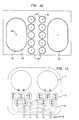
- Figs. 6A and 6Bshow two types of valves that can be used in the present invention.
- Fig. 7shows cross-sectional views of a disposable cartridge, or cassette, that can be used in the present invention.
- Fig. 8shows a bottom view of the disposable cassette of Fig. 7 and its internal piping.
- Fig. 9shows an end view of the disposable cassette of Fig. 7.
- Fig. 10shows a plan view of the face of the central system unit against which the disposable cassette of Fig. 7 is placed against.
- Fig. 11shows a top plan view of an alternative disposable cartridge and its internal piping.
- Fig. 12shows a cross-section of another alternative disposable in contact with the central unit.
- Fig. 1depicts a preferred embodiment of the present invention.
- a fluiddepicted by the hatching, is in a line 1 which in a typical application is an intravenous line running from a supply, e.g., an intravenous bag, to the patient.
- a rigid container 2Disposed in the line is a rigid container 2, having an input at valve A and an output at valve B. Valves A and B can be closed so that the container 2 is isolated from the effects of pressure in the rest of the line 1.
- the container 2is divided by a membrane 3, which separates that portion of the container that is filled with fluid from the remaining portion that is filled with a measurement gas, which is typically air.
- the membrane 3is pliable enough so that the pressure of the measurement gas is the same as the pressure of the fluid, and so that the membrane may move as the amount of liquid in the container changes.
- the container and valves A and Bare built into a disposable cartridge, so that the area of the system that comes in direct contact with the fluid can be removed, disposed, and replaced with another cartridge whenever the system is to be used on a different patient.
- Putting the container and valves A and B in a disposable cartridgeavoids the problems of trying to clean and sterilize those areas of the system that came into contact with the fluid. Because the container is often in a disposable cartridge, it can be referred to as the "disposable".
- Fig. 1shows a pressure transducer 4 for measuring the pressure, Pd, in the container (i.e., the disposable).
- the containeri.e., the disposable
- the pressure transducer 5 for measuring the pressure, Pr, in the reservoircan measure the pressure of the container when valve D is opened and the reservoir and the container thereby achieve the same pressure. Nevertheless, it is sometimes necessary or preferable to monitor the pressure, Pd, of the container when valve D is closed.
- Fig. 1also shows a reservoir, which is of a constant, known volume.
- the primary purpose of the reservoiris to measure how much of the container 2 is not filled with fluid. (Vu will be used to denote the "unoccupied volume" of the container.)
- the embodiment shown in Fig. 1uses the positive tank 8 or the negative tank 9 in addition to the reservoir, to measure Vu.
- Fig. 1shows a pump connected to the positive tank 8 by valve G and to the negative tank 9 by valve H. This pump is used to move the measurement gas from the negative tank 9 to the positive tank 8, thereby creating a higher pressure in the positive tank 8 and a lower pressure in the negative tank 9.
- valves G and Hare closed when the desired positive and negative pressures are obtained, and the pump is then turned off.
- Pressure transducers 6 and 7are used to monitor the pressures in the positive and negative tanks respectively.
- the positive and negative pressure suppliesi.e., the positive and negative tanks
- Vuthe volume of the unfilled portion of the container 2
- Vrthe volume of the reservoir
- step 9is derived using Boyle's Law for ideal gases.
- the volume of fluid in the container 2can be determined if the volume of the container 2 is known; merely subtract Vu, the unoccupied volume, from the total volume (occupied and unoccupied) of the container 2.
- This cycleis useful if one does not wish to wait for the pressures in the reservoir and the container to equalize; as may be the case if there is a long thin passage between the two so that it took some period of time after valve D was opened for the pressures to equalize.
- the volume of the reservoir, Vris chosen so that it is approximately the same as (or the same order of magnitude as) the volume of the unfilled portion of the container, Vu. This is preferred so that the changes in pressure in both the container and the reservoir are about the same, and thus errors in measuring the pressures or performing the volume calculations are minimized.
- the positive tank 8 and the negative tank 9are preferably much larger than the reservoir and the unfilled portion of the container 2.
- the reason for this preferenceis that the pressure in the tanks, Pp and Pn, are preferably kept at desired levels (by monitoring transducers 6 and 7 and activating the pump appropriately), and when either tank is exposed to the reservoir (by opening either valve J or K) the reservoir will pressurize to the pressure level of the tank, and the pressure level of the tank will not change much. Relative to the amount of gas in the tank, a small amount of gas has moved to the reservoir, thus the pressure in the tank is not altered much.
- This arrangementis desired when there is a desire or need to quickly pressurize the reservoir to a certain pressure, positive or negative.
- the positive and negative pressure sourcesin this embodiment the tanks
- the positive and negative pressure sourcescan be used to pump fluid through the line by alternatively applying suction and pressure to the membrane 3 of the container 2.
- a cycle using Fig. 1 embodiment for pumping fluid through the line at a controlled rateis set forth below.
- Fig. 2shows an alternative embodiment of the invention. It is very similar to the embodiment depicted in Fig. 1, except the positive and negative pressure sources, 8 and 9, can be applied directly to the container 2 without passing through the reservoir. Also, the reservoir can be vented to ambient pressure by opening valve F. By venting the reservoir, one can change the pressure, Pr, in the reservoir without using the positive and negative pressure sources, 8 and 9. A venting valve is also used in the Fig. 1 embodiment though not shown.
- Fig. 3shows a third embodiment of the invention, combining aspects of the embodiments depicted in Figs. 1 and 2.
- the Fig. 3 embodimentalso uses two separate pumps for pressurizing the positive and negative tanks, 8 and 9.
- the pressure in the two tankscan be controlled separately.
- the positive and negative pressure suppliesdo not necessarily need to use tanks, such as tanks 8 and 9, although the use of large tanks is preferred in order to better regulate the positive and negative pressure sources.
- a cycle using the Fig. 3 embodiment for controlling the flow of fluid through the line 1is set forth below. (Note that this particular cycle does not substantially pump the fluid through the line 1; rather outside forces, such as head pressure or a pump upstream and/or downstream of the container 2, is needed to move the fluid through the line 1. This cycle merely measures the flow rate, and, if the flow rate is too high, the controller can regulate the opening and closing of valves A and B in order to slow the flow rate.)
- the structures shown in Figs. 1-3can be used in a variety of ways to measure how much of the container 2 is not occupied by fluid (Vu).
- Other structurescan be used to measure Vu.
- the measurement apparatus 10 for measuring Vu, of Fig. 2, which includes the reservoir, valves D and F, and the pressure transducer 5,can be replaced with the alternative measurement apparatus shown in Fig. 5. All of the measurement apparatuses discussed herein, including that depicted in Fig. 5, use a measurement gas and Boyle's Law for measuring Vu. Other kinds of measurement apparatuses may be available, but it is felt that the ones disclosed herein are more accurate and less expensive.
- the measurement apparatus 10 shown in Fig. 4does also in combination with Fig. 2 not lie within the scope of the claims, since it does not have a reservoir that can be isolated from the container.
- Fig. 4is thus shown for illustration only.
- the volumeis changed by a piston 11 that is moved by a motor 12.
- the pressure measurementsare made by pressure transducer 4. This apparatus is described in greater detail in U.S. Patent No.
- the measurement apparatus 10 shown in Fig. 5can replace the measurement apparatus 10 of Fig. 1,2,3 and performs then in a manner similar to the measurement apparatus shown in Figs. 1, 2 and 3; the volume, Vr, of the reservoir must be known and fixed, and the pump 13, located where valve D is in Fig. 2, is used both to change the pressure in the reservoir (and the container 2) and to valve measurement gas between the reservoir and the container 2. (If the pump leaks gas when it is off, then of course, a valve, which can be closed to prevent fluid flow between the container 2 and the reservoir, should be placed in series with the pump.) Essentially, the way the Fig.
- valve systemhas been designed for use with the disposable cartridge embodiment above. Specifically, this valve system can be used for valves A and B in the above embodiments, since these valves come in contact with intravenous fluid and therefore should be part of the disposable cartridge.
- the valve systemis characterized by the use of a second control fluid, such as air. (The control fluid can be different than the measurement gas, but preferably both are air.)
- This control fluidurges a flexible membrane against a receiving surface such that a seal is formed and the line is closed off.
- the fluid line, flexible membrane, and receiving surfaceare arranged in such a mechanically advantageous manner that relatively little fluid pressure in the control line is required to close off fluid under relatively high pressure in the main line.
- Fig. 6AOne simple embodiment is shown in Fig. 6A, wherein a single valve is provided.
- the fluid line input 61 and output 62are mounted to a fluid tight valving chamber 63.
- this valving chamber 63be made of a rigid material, such as molded hard plastic.
- the valving chamberincludes fittings for the input and output lines.
- the valving chamberfurther includes a mouth 64 connected to the fluid input 61, which in the present embodiment displays a beveled contour to facilitate efficient sealing. However, it would also be possible to have a mouth 64 that is flush with the wall of the chamber.
- One wall of the valving chamberis provided with a flexible impermeable membrane 65, which is in communication with a control fluid supply line 66.
- the membrane 65is mounted with relation to the control fluid supply line 66 and the mouth 64 such that when control fluid pressure is increased in the control fluid supply line 66, the flexible membrane 65 is urged against the mouth 64.
- a materialis chosen for the membrane 65 such that the membrane "grips" the mouth 64, thereby enhancing the seal.
- the present embodimentincorporates mechanical advantage.
- the control fluidtends to distribute force all along the surface of the membrane. Because of its small diameter the fluid in the fluid input 61 only acts on a small area of the membrane 65. Thus, the control fluid line pressure can produce more force on the membrane than the fluid input pressure (force is equal to pressure times area).
- Fig. 6Bshows another embodiment of this valve, wherein two beveled mouths are used -- one for the input 64, one for the output 67. This embodiment is useful if the output fluid may be highly pressurized.
- pressure in the control fluid linecould be controlled using a stepper motor employing a cam-actuated piston or other means known in the art.
- a pistonwould be used to compress the air in the line, thereby increasing the control fluid pressure and closing the valve. The piston would then be retracted to decrease the control fluid pressure and open the valve.
- airwould serve as the control fluid. Air could then be stored in an airtight reservoir in communication with the fluid line. A compressor could be used to increase the air pressure in the line, and a solenoid-operated valve would be used to open a communication pathway between the reservoir and the control line, thereby increasing the pressure in the control line. (The foregoing can be controlled by a microprocessor.) When the valve is to be opened, the communication pathway would be closed, and the control line vented to ambient atmosphere. Alternatively, the reservoir could be pressurized using a hand pump.
- control fluid pressure generating meansRegardless of the specific embodiment for the control fluid pressure generating means, it will be seen that the present invention provides numerous advantages. Primary among these advantages is the combination of mechanical reliability with low cost and ease of manufacture.
- the valving systems of Figs. 6A and 6Bare mechanically reliable because they have relatively few moving parts.
- the valving chamberis fixed, as are the line fluid input, line fluid output, and the control fluid line.
- the only moving partsare the control fluid pressure generating means and the flexible membrane.
- the control fluid pressure generating meanscan be implemented using a stepper motor and piston. Piston assemblies, because of the limited range of motion involved, are also mechanically reliable.
- the control fluid pressure generating meanscan also be implemented using a pressurized air reservoir.
- valveconnecting the reservoir to the control fluid line, and the means used to pressurize the reservoir; furthermore, such a pressurized reservoir may be available in the fluid control system, such as the positive tanks 8 in the systems depicted in Figs. 1-3. (The negative tanks 9 could be used to pull the membrane 65 from the mouths.)
- the flexible membranecan be made of any of a number of readily available, inexpensive materials, for example, the flexible plastic used to make intravenous bags. This material is known to be extremely rugged, in addition to being relatively inexpensive. Further, this plastic has excellent "gripping" properties.
- Another advantage to using a membrane-based systemis that there are none of the known disadvantage inherent in valving systems based on squeezing an intravenous tube.
- the first disadvantage in squeezing systemsis that it is relatively difficult to obtain a perfect closing of the line. A relatively large amount of energy must be expended to pinch an intravenous line closed, because of the difficulty in "folding" the edges of a pinched tube.
- a further disadvantageis cold flow. An intravenous tube will, after repeated openings and closings, tend to change shape around the pinching site. This in turn decreases the mechanical reliability of the intravenous delivery system. None of these disadvantages are present in a membrane-based system. As discussed above, because of the mechanical advantage inherent in this system, relatively little energy is required to close the valve. And because there is no pinching involved, cold flow does not present a significant problem.
- valvedoes not require precision molding.
- the valvewill tolerate a broad range of manufacturing imperfections. For example, even if the valve chamber mouth is not perfectly aligned, the membrane will still seal against it. Even if the control fluid line is slightly off center, the membrane will still be urged against the valve chamber mouth.
- the only stringent requirementsare that the valve chamber, including input and output lines, be fluidtight, and that the control fluid line be airtight.
- this valving systemcan be enhanced by the manufacturing method used.
- the input line, valving chamber (including mouth), output line and membraneall into a single disposable unit that could also include the container 2 (more precisely half the container -- the half that is filled with liquid) shown in Figs. 1-5.
- the membranewould be attached to a rigid plastic structure that could be sized to fit snugly onto a central flow control system unit. Any of the various flow control systems discussed hereinabove could be adapted to work with a disposable.
- a flow control systemit is contemplated to mold the portion of the pressure/volume measurement housing containing intravenous fluid (the left half of container 2 in Figs. 1-5) together with input and output pathways and membrane-based valving chambers all out of the same block of plastic.
- the same sheet of membranecan be used as the membrane 65 in the valves and as the interface (See item 3 in Fig. 1) between the intravenous fluid and the measurement gas.
- Two such housing unitsare depicted in Figs. 7-9 and Fig. 11.
- the housing unitwould be affixed to a receiving block, such as that shown in Fig. 10, which would be used with the housing unit depicted in Figs. 7-9.
- the housing unitcould be held in place by a retaining clamp, or by other means known in the art. Sealing rings are provided to insure that the control fluid pathways, and the measurement gas pathways remain fluidtight.
- the housing unitwould be disposable, and that the receiving block would be an integral part of the central flow control system unit. It will be seen that this is a desirable arrangement.
- the housing unitis used to transport intravenous fluid, and must therefore be sterile. It would be impractical to clean and sterilize such a unit for multiple uses.
- the receiving blockon the other hand, must be sturdy, to ensure a proper seal, and to ensure proper operation of the valves.
- controlleri.e., the microprocessor
- the controllercould be programmed to perform a safety protocol during calibration of the device to check that all the seals are tight.
- control fluid pressure to various valving chamberswould be manipulated, and the resulting pressure changes would be monitored using the pressure transducers already present in the system. Aberrant conditions would cause an alarm state to be entered into.
- Fig. 7shows one embodiment of a disposable housing unit (or “cartridge” or “cassette”).
- This particular unithas two concave indentations 71 for the container portion of the disposable, so that two fluid control systems can function in parallel.
- two fluid control systemsare'used to deliver intravenous fluid to a patient in order to make the flow of fluid smoother.
- the otheris filling.
- fluidis delivered in more closely spaced and smaller pulses, rather than larger pulses that come less frequently and that have longer periods between them.
- the disposable cartridge shown in Fig. 7also has ten valves 72 of the type depicted in Fig. 6A, with the input 61 and the output 62 showing.
- This side of the unithas a membrane stretched across and attached to it that serves as the membrane (65 in Fig. 6A) for the valves 72 and the membrane (3 in Fig. 1) for the container 71. (See item 91 in Fig. 9.)
- Fig. 8shows a bottom view of the disposable cartridge showing the internal piping or passageways 81, which are inside the disposable cartridge and which connect the various valves 72, the container indentations 71 and the various inputs and outputs 82-86.
- the inputs and outputscan be arranged in a variety of ways; for example, the top two ports 82 and 83 could both be inputs (i.e, valve A in Figs. 1-5) coming from two different fluid supplies, the bottom two ports 85 and 86 could be outputs (i.e., valve B in Figs. 1-5).
- Port 84could be used to remove samples of the fluid from the container for testing or analyzing.
- FIG. 9shows an end view of these ports 82-86, as well as the fluid side of the containers 71 in phantom.
- the membrane 91 for the valves 72 and the containers 71is attached to the disposable cartridge on the side indicated (91).
- the membrane 91billows in and out depending on how much fluid is in the container.
- Fig. 10shows the face of the flow control system unit, against which the disposable shown in Figs. 7-9 is placed and held by a clamping device.
- These indentations 101 on the system unitare basically the measurement gas portion of the container.
- Each indentationhas an aperture 103, through which measurement gas passes.
- the measurement gasis used to measure how much of the complete container is not occupied by the fluid (when the container is isolated), to suction fluid into the container, and to force fluid out of the container.
- Fig. 10also shows receptacles 102 for the valves 72 and an aperture 66, through which the valve control fluid passes.
- the container indentations 101 and the valve receptacles 102are surrounded by seals, 105 and 106 respectively, so that when the disposable is clamped against the system unit an air-tight seal is formed.
- Fig. 11shows an alternative disposable housing unit that like the disposable housing unit in Figs. 7-9 has container indentations 71, fluid pathways 81 and input/output ports 82-86.
- the Fig. 11 disposableuses the valves 111 shown in Fig. 6B. Despite this difference and the different piping layout, the Fig. 11 disposable functions the same way as the disposable in Figs. 7-9.
- Fig. 12shows a simple embodiment of the disposable housing unit 124 clamped against the face of the central flow control unit 125 designed for this disposable 124.
- This disposable 124has only one container 2 and two valves, A and B, and therefore can be used with any of the embodiments depicted in Figs. 1-5.
- the input 61a of valve Ais connected to the intravenous line 1 by a protrusion 121, which can be inserted in the intravenous tubing.
- Valve A and valve Bare of the type depicted in Fig. 5B; the two beveled mouths 64a and 67a can be seen in valve A.
- the output 62a of valve Aleads in to the left half of the container 2, which is formed by the indentation 71 in the disposable 124.
- Membrane sheet 91is attached to the disposable 124 and covers the whole side of the disposable. Parts of this membrane sheet 91 function as the membrane 65a for valve A, the membrane 3 in the container 2, and the membrane 65b in valve B. Valve A is disposed against a receptacle 102a in the central unit 125, which is connected to an air supply 66a through which air is pumped back and forth, thereby effecting the opening and closing of valve A by pulling the membrane 65a back from the mouths 64a and 67a and pushing the membrane 65a against mouths 64a and 67a. In this case, the air is functioning as the valve control fluid.
- Channel 103provides a path for the measurement gas (which can be air) from the container 2 to the rest of the system (including, for example, the reservoir).
- the container 2is connected to the input 61b of valve B, which is disposed against the receptacle 102b and which functions the same way as valve A by means of air supply 66b.
- the output 62bflows into the intravenous line 1 connected to the patient.
- a protrusion 122is used to attach the tube to the disposable 124.
Landscapes
- Engineering & Computer Science (AREA)
- Health & Medical Sciences (AREA)
- General Engineering & Computer Science (AREA)
- General Physics & Mathematics (AREA)
- Fluid Mechanics (AREA)
- Physics & Mathematics (AREA)
- Mechanical Engineering (AREA)
- Heart & Thoracic Surgery (AREA)
- Biomedical Technology (AREA)
- General Health & Medical Sciences (AREA)
- Public Health (AREA)
- Veterinary Medicine (AREA)
- Life Sciences & Earth Sciences (AREA)
- Hematology (AREA)
- Animal Behavior & Ethology (AREA)
- Anesthesiology (AREA)
- Vascular Medicine (AREA)
- Measuring Fluid Pressure (AREA)
- Infusion, Injection, And Reservoir Apparatuses (AREA)
- Measuring Volume Flow (AREA)
- External Artificial Organs (AREA)
- Flow Control (AREA)
- Control Of Fluid Pressure (AREA)
Abstract
Description
- Step 1 -
- ISOLATE THE CONTAINER:
close valves A and B. - Step 2 -
- EQUALIZE PRESSURE IN THE CONTAINER AND THERESERVOIR:
open valve D. - Step 3 -
- MEASURE PRESSURE P1 IN THE CONTAINER:
read Pr fromtransducer 5. - Step 4 -
- ISOLATE THE CONTAINER FROM THE RESERVOIR:
close valve D. - Step 5 -
- CHANGE PRESSURE IN RESERVOIR:
open valve J to expose the reservoir to thehigher pressure from the positive pressuresource (or, in the alternative, open valve Kto expose the reservoir to the lower pressurefrom the negative pressure source). - Step 6 -
- MEASURE PRESSURE P2 IN THE RESERVOIR:
read Pr from thetransducer 5. - Step 7 -
- EQUALIZE PRESSURE IN THE CONTAINER AND THERESERVOIR:
open valve D. - Step 8 -
- MEASURE PRESSURE P3 IN THE CONTAINER:
read Pr fromtransducer 5. - Step 9 -
- CALCULATE Vu:
- solve
- Vu = -((P3-P2)Vr)/(P3-P1),
- where Vr is the volume of the reservoir.
- Step 1 -
- ISOLATE THE CONTAINER:
close valves A, B, and D. - Step 2 -
- (eliminated)
- Step 3 -
- MEASURE PRESSURE Pd1 IN THE CONTAINER:
read Pdl from transducer 4. - Step 4 -
- (eliminated)
- Step 5 -
- CHANGE PRESSURE IN RESERVOIR IF SAME ASPRESSURE Pdl IN CONTAINER:
read Pr fromtransducer 5, and if necessaryopen either valve J or valve K. - Step 6 -
- MEASURE PRESSURE Pr1 IN THE RESERVOIR:
read Pr1 fromtransducer 5. - Step 7 -
- ALLOW SOME MEASUREMENT GAS TO FLOW BETWEENTHE RESERVOIR AND THE CONTAINER:
open and close valve D. - Step 8 -
- MEASURE PRESSURES Pd2 IN THE CONTAINER ANDPr2 IN THE RESERVOIR:
readtransducers 4 and 5. - Step 9 -
- CALCULATE Vu:
- solve
- Vu=-((Pr2-Pr1)Vr)/ (Pd2-Pd1).
close valves A and K.
open valves B and J. (Note: valve D isopen.)
close valves B and J.
subtract the final volume calculated in
close valve F.
close valves A and E.
open valves B and C.
close valves B and C.
perform substeps (i) - (viii) of Step 4; andcalculate final volume of fluid in container(or the final Vu).
subtract the final volume calculated in
- Step 1 -
- INITIALIZE:
close valves C, E, F, J and K. - Step 2 -
- FILL CONTAINER:
- close valve B; and
- open valve A. (Note: sufficient pressureabove valve A is required to force the fluidinto the container in this non-pump cycle.)
- Step 3 -
- PERFORM VOLUME CALCULATION SUBCYCLE:
- (i) equalize pressure between container andreservoir by opening valve D;
- (ii) read pressure in the container;
- (iii) isolate the container from the reservoirby closing valve D;
- (iv) change pressure in the reservoir byopening and then closing valve F orvalve J or valve K;
- (v) read pressure in the reservoir;
- (vi) equalize pressure between container andreservoir by opening valve D;
- (vii) read new pressure in container; and
- (viii) calculate initial volume of fluid incontainer (or initial Vu).
- Step 5 -
- DELIVER FLUID:
open valve B. (Note: sufficient suctionbelow valve B is required to force fluid outof the container in this cycle.) - Step 6 -
- ISOLATE CONTAINER:
close valve B. - Step 7 -
- REPEAT VOLUME CALCULATION SUBCYCLE:
- perform substeps (i) - (vii) of Step 4; and
- calculate final volume of fluid in container(or final Vu).
- Step 8 -
- CALCULATE VOLUME DELIVERED (in Step 5):
subtract the final volume calculated inStep 7 from the initial volume calculated in Step4 (or subtract the initial Vu calculated inStep 4 from the final Vu calculated in Step7).
Claims (3)
- A system for controlling flow of a liquidthrough a line, the system comprisinga rigid container (2) for holding a region of theliquid in the line (1), the rigid container having alarger volume than the region of liquid, wherein ameasurement gas fills the portion of the rigidcontainer not occupied by the liquid, so that themeasurement gas is in pressure communication with theliquid in the container,an input valve (A) for permitting, when opened,liquid to flow from the line (1) into the container(2),output valve means (B) for permitting, whenopened, liquid to be delivered from the container tothe line (1), wherein when both the input and outputvalves are closed, the region of the liquid in thecontainer is isolated from effects of pressure in theline outside the region,a positive pressure reservoir (8);a positive pressure valve for, upon activation,allowing measurement gas to pass from the positive pressurereservoir to the container (2);a negative pressure reservoir (9) distinct and different from the positive pressure reservoir (8);a negative pressure valve for, upon actuation,allowing measurement gas to pass from the container (2)to the negative pressure reservoir,control means for controlling the input, output,positive-pressure and negative-pressure valves,a common reservoir (10) for holding a fixed, knownvolume of the measurement gas, the common reservoirbeing distinct and different from the positive pressurereservoir and the negative pressure reservoir;a reservoir valve (D), located between thecontainer (2) and the common reservoir, for, in a firstvalve position, permitting the measurement gas to flow between the container and the common reservoir whenopened, and, in a second valve position, preventing themeasurement gas from flowing between the container andthe common reservoir;reservoir transducer means (5) for measuring thepressure in the common reservoir; anda vent valve, which is distinct and different from the positive and negative pressure valves, for permitting the measurement gas toflow between the common reservoir and the atmosphere,wherein the control means includes means forreading pressure measurements from the reservoirtransducer means, for controlling the reservoir valve(D) and the vent valve, and calculating the volume, Vu,of that portion of the container not occupied by liquidbased on the pressure measurements and the volume, Vr,of the common reservoir, andwherein thecontainer (2) includes a disposable portion (124) whichcan be quickly disconnected from the remainder of thesystem, the disposable portion including all thoseportions of the container and the input and outputvalves means (A, B) which come into contact with theliquid.
- A system according to claim 1, whereinthe positive and negative pressure reservoirs furthercomprise pump means and wherein the control meansfurther comprises means for activating the pump means.
- A system according to any preceding claim,further comprising means for performing the followingcycle of steps:closing the output valve (B);opening the input valve (A);activating and de-activating the negative pressurereservoir;closing the input valve (A);determining the initial volume, Vu1, of thatportion of the container (2) not occupied by liquid;opening the output valve (B);activating and de-activating the positive pressurereservoir;closing the output valve (B);determining the final volume, Vu2, of that portionof the container (2) not occupied by liquid; andsubtracting Vu1 from Vu2 to determine the amountof liquid that left the container (2) while the outputvalve (B) was open.
Applications Claiming Priority (3)
| Application Number | Priority Date | Filing Date | Title |
|---|---|---|---|
| US07/345,387US4976162A (en) | 1987-09-03 | 1989-05-01 | Enhanced pressure measurement flow control system |
| US345387 | 1989-05-01 | ||
| PCT/US1990/002321WO1990013795A2 (en) | 1989-05-01 | 1990-04-27 | Enhanced pressure measurement flow control system |
Publications (2)
| Publication Number | Publication Date |
|---|---|
| EP0471000A1 EP0471000A1 (en) | 1992-02-19 |
| EP0471000B1true EP0471000B1 (en) | 1998-12-30 |
Family
ID=23354846
Family Applications (1)
| Application Number | Title | Priority Date | Filing Date |
|---|---|---|---|
| EP90907593AExpired - LifetimeEP0471000B1 (en) | 1989-05-01 | 1990-04-27 | Enhanced pressure measurement flow control system |
Country Status (9)
| Country | Link |
|---|---|
| US (1) | US4976162A (en) |
| EP (1) | EP0471000B1 (en) |
| JP (1) | JP2952037B2 (en) |
| KR (1) | KR0166337B1 (en) |
| AT (1) | ATE175270T1 (en) |
| CA (1) | CA2049337C (en) |
| DE (1) | DE69032869T2 (en) |
| DK (1) | DK0471000T3 (en) |
| WO (1) | WO1990013795A2 (en) |
Cited By (5)
| Publication number | Priority date | Publication date | Assignee | Title |
|---|---|---|---|---|
| WO2005009512A1 (en) | 2003-07-31 | 2005-02-03 | Debiotech S.A. | A system for performing fluid administration |
| WO2005009511A2 (en) | 2003-07-31 | 2005-02-03 | Debiotech S.A. | A system for performing peritoneal dialysis |
| WO2014068475A2 (en) | 2012-10-29 | 2014-05-08 | Debiotech S.A. | Device for extracorporeal blood treatment |
| WO2016059614A2 (en) | 2014-10-17 | 2016-04-21 | Debiotech S.A. | Delivery system and mode of operation thereof |
| WO2016193930A1 (en) | 2015-06-03 | 2016-12-08 | Debiotech S.A. | Peritoneal dialysis treatment system and method of operation |
Families Citing this family (218)
| Publication number | Priority date | Publication date | Assignee | Title |
|---|---|---|---|---|
| US5575310A (en)* | 1986-03-04 | 1996-11-19 | Deka Products Limited Partnership | Flow control system with volume-measuring system using a resonatable mass |
| US5195986A (en)* | 1986-03-04 | 1993-03-23 | Deka Products Limited Partnership | Integral intravenous fluid delivery device |
| US5364371A (en)* | 1986-03-04 | 1994-11-15 | Deka Products Limited Partnership | Intravenous fluid delivery device |
| US5349852A (en)* | 1986-03-04 | 1994-09-27 | Deka Products Limited Partnership | Pump controller using acoustic spectral analysis |
| US5088515A (en)* | 1989-05-01 | 1992-02-18 | Kamen Dean L | Valve system with removable fluid interface |
| US4983102A (en)* | 1988-10-14 | 1991-01-08 | Swain Danny C | Self-enclosed filter pumping system |
| ATE162621T1 (en)* | 1990-11-19 | 1998-02-15 | Deka Products Lp | PUMP CONTROL DEVICE WITH ACOUSTIC SPECTRAL ANALYSIS |
| WO1992008503A2 (en)* | 1990-11-19 | 1992-05-29 | Deka Products Limited Partnership | Integral intravenous fluid delivery device |
| US5560247A (en)* | 1992-09-16 | 1996-10-01 | Honda Giken Kogyo Kabushiki Kaisha | Exhaust gas sampling device for outboard motor |
| US5431626A (en)* | 1993-03-03 | 1995-07-11 | Deka Products Limited Partnership | Liquid pumping mechanisms for peritoneal dialysis systems employing fluid pressure |
| US5324422A (en)* | 1993-03-03 | 1994-06-28 | Baxter International Inc. | User interface for automated peritoneal dialysis systems |
| US5438510A (en)* | 1993-03-03 | 1995-08-01 | Deka Products Limited Partnership | User interface and monitoring functions for automated peritoneal dialysis systems |
| US5474683A (en)* | 1993-03-03 | 1995-12-12 | Deka Products Limited Partnership | Peritoneal dialysis systems and methods employing pneumatic pressure and temperature-corrected liquid volume measurements |
| US5350357A (en)* | 1993-03-03 | 1994-09-27 | Deka Products Limited Partnership | Peritoneal dialysis systems employing a liquid distribution and pumping cassette that emulates gravity flow |
| EP0847769B1 (en)* | 1993-03-03 | 2001-08-29 | Deka Products Limited Partnership | Peritoneal dialysis cassette |
| US5447286A (en)* | 1994-01-21 | 1995-09-05 | Deka Products Limited Partnership | High flow valve |
| US5421208A (en)* | 1994-05-19 | 1995-06-06 | Baxter International Inc. | Instantaneous volume measurement system and method for non-invasively measuring liquid parameters |
| US5640995A (en)* | 1995-03-14 | 1997-06-24 | Baxter International Inc. | Electrofluidic standard module and custom circuit board assembly |
| US6210361B1 (en) | 1997-08-22 | 2001-04-03 | Deka Products Limited Partnership | System for delivering intravenous drugs |
| US5938634A (en)* | 1995-09-08 | 1999-08-17 | Baxter International Inc. | Peritoneal dialysis system with variable pressure drive |
| FR2739446B1 (en)* | 1995-09-28 | 1997-10-24 | Inst Francais Du Petrole | METHOD FOR MEASURING WITH VERY PRECISION THE VARIATION IN VOLUME INTERVENING DURING THE MIXTURE OF FLUID PHASES, FOR THE PURPOSE OF DETERMINING PHYSICO-CHEMICAL CHARACTERISTICS |
| DE19546028C2 (en)* | 1995-12-09 | 2000-04-27 | Fresenius Ag | Balancing disposable for balancing liquids for a medical treatment device and a medical treatment device with a system insert for receiving such a balancing disposable |
| US6036296A (en)* | 1996-10-31 | 2000-03-14 | Hewlett-Packard Company | Fluid level detection apparatus and method for determining the volume of fluid in a container |
| JP3970938B2 (en)* | 1996-11-22 | 2007-09-05 | セラコス・インコーポレイテッド | Fluid pump device with constant flow rate |
| EP1512975A3 (en)* | 1997-04-08 | 2006-05-24 | Packard Instrument Company, Inc. | Microvolume liquid handling system |
| US6070761A (en)* | 1997-08-22 | 2000-06-06 | Deka Products Limited Partnership | Vial loading method and apparatus for intelligent admixture and delivery of intravenous drugs |
| GB9724223D0 (en)* | 1997-11-18 | 1998-01-14 | Pa Consulting Services | Drug delivery device |
| DE19805236C2 (en)* | 1998-02-10 | 2000-02-24 | Dietrich Engmann | Method and device for determining the volume of a ceramic specimen |
| US6041801A (en)* | 1998-07-01 | 2000-03-28 | Deka Products Limited Partnership | System and method for measuring when fluid has stopped flowing within a line |
| AU2003200025B2 (en)* | 1998-07-01 | 2006-06-29 | Deka Products Limited Partnership | A fluid management system |
| US6223130B1 (en) | 1998-11-16 | 2001-04-24 | Deka Products Limited Partnership | Apparatus and method for detection of a leak in a membrane of a fluid flow control system |
| US6382923B1 (en)* | 1999-07-20 | 2002-05-07 | Deka Products Ltd. Partnership | Pump chamber having at least one spacer for inhibiting the pumping of a gas |
| US6905479B1 (en) | 1999-07-20 | 2005-06-14 | Deka Products Limited Partnership | Pumping cartridge having an integrated filter and method for filtering a fluid with the cartridge |
| US6416293B1 (en)* | 1999-07-20 | 2002-07-09 | Deka Products Limited Partnership | Pumping cartridge including a bypass valve and method for directing flow in a pumping cartridge |
| US6302653B1 (en)* | 1999-07-20 | 2001-10-16 | Deka Products Limited Partnership | Methods and systems for detecting the presence of a gas in a pump and preventing a gas from being pumped from a pump |
| US6877713B1 (en) | 1999-07-20 | 2005-04-12 | Deka Products Limited Partnership | Tube occluder and method for occluding collapsible tubes |
| US6604908B1 (en)* | 1999-07-20 | 2003-08-12 | Deka Products Limited Partnership | Methods and systems for pulsed delivery of fluids from a pump |
| US6495366B1 (en) | 1999-09-03 | 2002-12-17 | Therakos, Inc. | Uninterrupted flow pump apparatus and method |
| US8722422B2 (en) | 1999-09-03 | 2014-05-13 | Therakos, Inc. | Uninterrupted flow pump apparatus and method |
| US6497676B1 (en) | 2000-02-10 | 2002-12-24 | Baxter International | Method and apparatus for monitoring and controlling peritoneal dialysis therapy |
| CA2401712C (en)* | 2000-02-11 | 2007-04-10 | Hydac Technology Gmbh | Device for removing fluid from a container |
| US6793643B1 (en) | 2000-04-21 | 2004-09-21 | Therakos, Inc. | Low extracorporeal volume treatment system |
| US6503062B1 (en)* | 2000-07-10 | 2003-01-07 | Deka Products Limited Partnership | Method for regulating fluid pump pressure |
| US6905314B2 (en) | 2001-10-16 | 2005-06-14 | Baxter International Inc. | Pump having flexible liner and compounding apparatus having such a pump |
| US6769231B2 (en) | 2001-07-19 | 2004-08-03 | Baxter International, Inc. | Apparatus, method and flexible bag for use in manufacturing |
| US7311693B2 (en)* | 2001-11-26 | 2007-12-25 | Nilimedix Ltd. | Drug delivery device and method |
| US20030125662A1 (en) | 2002-01-03 | 2003-07-03 | Tuan Bui | Method and apparatus for providing medical treatment therapy based on calculated demand |
| WO2003086509A1 (en) | 2002-04-11 | 2003-10-23 | Deka Products Limited Partnership | System and method for delivering a target volume of fluid |
| US6929751B2 (en)* | 2002-05-24 | 2005-08-16 | Baxter International Inc. | Vented medical fluid tip protector methods |
| US7087036B2 (en) | 2002-05-24 | 2006-08-08 | Baxter International Inc. | Fail safe system for operating medical fluid valves |
| US7175606B2 (en) | 2002-05-24 | 2007-02-13 | Baxter International Inc. | Disposable medical fluid unit having rigid frame |
| US7153286B2 (en) | 2002-05-24 | 2006-12-26 | Baxter International Inc. | Automated dialysis system |
| DE10224750A1 (en) | 2002-06-04 | 2003-12-24 | Fresenius Medical Care De Gmbh | Device for the treatment of a medical fluid |
| MXPA05000817A (en) | 2002-07-19 | 2005-04-28 | Baxter Int | Systems and methods for performing peritoneal dialysis. |
| US11273245B2 (en) | 2002-07-19 | 2022-03-15 | Baxter International Inc. | Dialysis system having a vented disposable dialysis fluid carrying member |
| US7238164B2 (en) | 2002-07-19 | 2007-07-03 | Baxter International Inc. | Systems, methods and apparatuses for pumping cassette-based therapies |
| US7008403B1 (en)* | 2002-07-19 | 2006-03-07 | Cognitive Ventures Corporation | Infusion pump and method for use |
| US7007824B2 (en) | 2003-01-24 | 2006-03-07 | Baxter International Inc. | Liquid dispenser and flexible bag therefor |
| US20040144799A1 (en)* | 2003-01-24 | 2004-07-29 | Baxter International Inc. | Liquid dispenser and flexible bag therefor |
| WO2004094823A2 (en) | 2003-04-23 | 2004-11-04 | Biovalve Technologies, Inc. | Hydraulically actuated pump for long duration medicament administration |
| US20050005708A1 (en)* | 2003-07-08 | 2005-01-13 | Guy Dickes | Electronic volume measuring equipment |
| EP1680155B2 (en) | 2003-10-28 | 2015-11-04 | Baxter International Inc. | Dialysis machine with improved integrity test |
| US8158102B2 (en) | 2003-10-30 | 2012-04-17 | Deka Products Limited Partnership | System, device, and method for mixing a substance with a liquid |
| US7632078B2 (en) | 2003-10-30 | 2009-12-15 | Deka Products Limited Partnership | Pump cassette bank |
| US7662139B2 (en) | 2003-10-30 | 2010-02-16 | Deka Products Limited Partnership | Pump cassette with spiking assembly |
| US8029454B2 (en) | 2003-11-05 | 2011-10-04 | Baxter International Inc. | High convection home hemodialysis/hemofiltration and sorbent system |
| US7776006B2 (en) | 2003-11-05 | 2010-08-17 | Baxter International Inc. | Medical fluid pumping system having real time volume determination |
| US9089636B2 (en) | 2004-07-02 | 2015-07-28 | Valeritas, Inc. | Methods and devices for delivering GLP-1 and uses thereof |
| US20060195064A1 (en)* | 2005-02-28 | 2006-08-31 | Fresenius Medical Care Holdings, Inc. | Portable apparatus for peritoneal dialysis therapy |
| US7935074B2 (en) | 2005-02-28 | 2011-05-03 | Fresenius Medical Care Holdings, Inc. | Cassette system for peritoneal dialysis machine |
| US8197231B2 (en) | 2005-07-13 | 2012-06-12 | Purity Solutions Llc | Diaphragm pump and related methods |
| US12070574B2 (en) | 2006-02-09 | 2024-08-27 | Deka Products Limited Partnership | Apparatus, systems and methods for an infusion pump assembly |
| US11364335B2 (en) | 2006-02-09 | 2022-06-21 | Deka Products Limited Partnership | Apparatus, system and method for fluid delivery |
| EP3165247B1 (en) | 2006-02-09 | 2020-10-28 | DEKA Products Limited Partnership | Pumping fluid delivery systems and methods using force application assembley |
| US10010669B2 (en) | 2006-02-09 | 2018-07-03 | Deka Products Limited Partnership | Systems and methods for fluid delivery |
| US11027058B2 (en) | 2006-02-09 | 2021-06-08 | Deka Products Limited Partnership | Infusion pump assembly |
| US11478623B2 (en) | 2006-02-09 | 2022-10-25 | Deka Products Limited Partnership | Infusion pump assembly |
| US8579884B2 (en) | 2006-02-09 | 2013-11-12 | Deka Products Limited Partnership | Infusion pump assembly |
| US12274857B2 (en) | 2006-02-09 | 2025-04-15 | Deka Products Limited Partnership | Method and system for shape-memory alloy wire control |
| US12151080B2 (en) | 2006-02-09 | 2024-11-26 | Deka Products Limited Partnership | Adhesive and peripheral systems and methods for medical devices |
| US11497846B2 (en) | 2006-02-09 | 2022-11-15 | Deka Products Limited Partnership | Patch-sized fluid delivery systems and methods |
| US20110028937A1 (en)* | 2006-02-27 | 2011-02-03 | Fluidnet Corporation | Automated fluid flow control system |
| US20090131863A1 (en)* | 2006-02-27 | 2009-05-21 | Fluidnet Corporation | Volume Measurement Using Gas Laws |
| US10010686B2 (en) | 2006-02-27 | 2018-07-03 | Ivenix, Inc. | Fluid control system and disposable assembly |
| US9146564B2 (en) | 2006-03-06 | 2015-09-29 | Deka Products Limited Partnership | Product dispensing system |
| JP2009531118A (en)* | 2006-03-29 | 2009-09-03 | コーニンクレッカ フィリップス エレクトロニクス エヌ ヴィ | Fluid processing and volume determination system |
| WO2007115039A2 (en) | 2006-03-30 | 2007-10-11 | Valeritas, Llc | Multi-cartridge fluid delivery device |
| US9717834B2 (en) | 2011-05-24 | 2017-08-01 | Deka Products Limited Partnership | Blood treatment systems and methods |
| US8273049B2 (en) | 2007-02-27 | 2012-09-25 | Deka Products Limited Partnership | Pumping cassette |
| US7794141B2 (en) | 2006-04-14 | 2010-09-14 | Deka Products Limited Partnership | Thermal and coductivity sensing systems, devices and methods |
| US8366316B2 (en) | 2006-04-14 | 2013-02-05 | Deka Products Limited Partnership | Sensor apparatus systems, devices and methods |
| US20140199193A1 (en) | 2007-02-27 | 2014-07-17 | Deka Products Limited Partnership | Blood treatment systems and methods |
| US10537671B2 (en) | 2006-04-14 | 2020-01-21 | Deka Products Limited Partnership | Automated control mechanisms in a hemodialysis apparatus |
| US8926550B2 (en) | 2006-08-31 | 2015-01-06 | Fresenius Medical Care Holdings, Inc. | Data communication system for peritoneal dialysis machine |
| US8870811B2 (en) | 2006-08-31 | 2014-10-28 | Fresenius Medical Care Holdings, Inc. | Peritoneal dialysis systems and related methods |
| CA2677667A1 (en) | 2007-02-09 | 2008-08-14 | Deka Products Limited Partnership | Automated insertion assembly |
| US8361023B2 (en) | 2007-02-15 | 2013-01-29 | Baxter International Inc. | Dialysis system with efficient battery back-up |
| US7731689B2 (en) | 2007-02-15 | 2010-06-08 | Baxter International Inc. | Dialysis system having inductive heating |
| US7998115B2 (en) | 2007-02-15 | 2011-08-16 | Baxter International Inc. | Dialysis system having optical flowrate detection |
| US8870812B2 (en) | 2007-02-15 | 2014-10-28 | Baxter International Inc. | Dialysis system having video display with ambient light adjustment |
| US8558964B2 (en) | 2007-02-15 | 2013-10-15 | Baxter International Inc. | Dialysis system having display with electromagnetic compliance (“EMC”) seal |
| US20090107335A1 (en) | 2007-02-27 | 2009-04-30 | Deka Products Limited Partnership | Air trap for a medical infusion device |
| US8491184B2 (en) | 2007-02-27 | 2013-07-23 | Deka Products Limited Partnership | Sensor apparatus systems, devices and methods |
| US8357298B2 (en) | 2007-02-27 | 2013-01-22 | Deka Products Limited Partnership | Hemodialysis systems and methods |
| US8562834B2 (en) | 2007-02-27 | 2013-10-22 | Deka Products Limited Partnership | Modular assembly for a portable hemodialysis system |
| US8042563B2 (en) | 2007-02-27 | 2011-10-25 | Deka Products Limited Partnership | Cassette system integrated apparatus |
| US8409441B2 (en) | 2007-02-27 | 2013-04-02 | Deka Products Limited Partnership | Blood treatment systems and methods |
| WO2010027437A2 (en) | 2007-02-27 | 2010-03-11 | Deka Products Limited Partnership | Blood treatment systems and methods |
| US9028691B2 (en) | 2007-02-27 | 2015-05-12 | Deka Products Limited Partnership | Blood circuit assembly for a hemodialysis system |
| KR102444304B1 (en) | 2007-02-27 | 2022-09-19 | 데카 프로덕츠 리미티드 파트너쉽 | hemodialysis system |
| US8393690B2 (en) | 2007-02-27 | 2013-03-12 | Deka Products Limited Partnership | Enclosure for a portable hemodialysis system |
| US8425471B2 (en) | 2007-02-27 | 2013-04-23 | Deka Products Limited Partnership | Reagent supply for a hemodialysis system |
| WO2008150776A2 (en) | 2007-05-29 | 2008-12-11 | Fresenius Medical Care Holdings, Inc. | Solutions, dialysates, and related methods |
| US8715235B2 (en) | 2007-07-05 | 2014-05-06 | Baxter International Inc. | Dialysis system having disposable cassette and heated cassette interface |
| US7909795B2 (en) | 2007-07-05 | 2011-03-22 | Baxter International Inc. | Dialysis system having disposable cassette and interface therefore |
| US7892197B2 (en) | 2007-09-19 | 2011-02-22 | Fresenius Medical Care Holdings, Inc. | Automatic prime of an extracorporeal blood circuit |
| US8771508B2 (en) | 2008-08-27 | 2014-07-08 | Deka Products Limited Partnership | Dialyzer cartridge mounting arrangement for a hemodialysis system |
| US8863772B2 (en) | 2008-08-27 | 2014-10-21 | Deka Products Limited Partnership | Occluder for a medical infusion system |
| WO2009049235A2 (en) | 2007-10-12 | 2009-04-16 | Deka Products Limited Partnership | Systems, devices and methods for cardiopulmonary treatment and procedures |
| US7905853B2 (en) | 2007-10-30 | 2011-03-15 | Baxter International Inc. | Dialysis system having integrated pneumatic manifold |
| US10188787B2 (en) | 2007-12-31 | 2019-01-29 | Deka Products Limited Partnership | Apparatus, system and method for fluid delivery |
| CA2919786C (en) | 2007-12-31 | 2019-10-22 | Deka Products Limited Partnership | Infusion pump assembly |
| US9456955B2 (en) | 2007-12-31 | 2016-10-04 | Deka Products Limited Partnership | Apparatus, system and method for fluid delivery |
| US8881774B2 (en) | 2007-12-31 | 2014-11-11 | Deka Research & Development Corp. | Apparatus, system and method for fluid delivery |
| US8900188B2 (en) | 2007-12-31 | 2014-12-02 | Deka Products Limited Partnership | Split ring resonator antenna adapted for use in wirelessly controlled medical device |
| US9526830B2 (en) | 2007-12-31 | 2016-12-27 | Deka Products Limited Partnership | Wearable pump assembly |
| US10080704B2 (en) | 2007-12-31 | 2018-09-25 | Deka Products Limited Partnership | Apparatus, system and method for fluid delivery |
| US9078971B2 (en) | 2008-01-23 | 2015-07-14 | Deka Products Limited Partnership | Medical treatment system and methods using a plurality of fluid lines |
| US8708950B2 (en) | 2010-07-07 | 2014-04-29 | Deka Products Limited Partnership | Medical treatment system and methods using a plurality of fluid lines |
| US10201647B2 (en) | 2008-01-23 | 2019-02-12 | Deka Products Limited Partnership | Medical treatment system and methods using a plurality of fluid lines |
| JP5595930B2 (en) | 2008-01-23 | 2014-09-24 | デカ・プロダクツ・リミテッド・パートナーシップ | Disposable components for fluid line automatic connection systems |
| US11833281B2 (en) | 2008-01-23 | 2023-12-05 | Deka Products Limited Partnership | Pump cassette and methods for use in medical treatment system using a plurality of fluid lines |
| US8986253B2 (en) | 2008-01-25 | 2015-03-24 | Tandem Diabetes Care, Inc. | Two chamber pumps and related methods |
| US20090191067A1 (en)* | 2008-01-25 | 2009-07-30 | Phluid,Inc. | Two chamber pumps and related methods |
| US7895882B2 (en)* | 2008-03-14 | 2011-03-01 | Fluidnet Corporation | Density analysis for flow sensor-based fluid control system |
| US7847276B2 (en)* | 2008-03-14 | 2010-12-07 | Fluidnet Corporation | Impulse analysis for flow sensor-based fluid control system |
| US8062513B2 (en) | 2008-07-09 | 2011-11-22 | Baxter International Inc. | Dialysis system and machine having therapy prescription recall |
| US9514283B2 (en) | 2008-07-09 | 2016-12-06 | Baxter International Inc. | Dialysis system having inventory management including online dextrose mixing |
| WO2010006610A1 (en)* | 2008-07-18 | 2010-01-21 | Diramo A/S | A system and method for determining a residual volume of a container unit |
| US8056582B2 (en) | 2008-08-08 | 2011-11-15 | Tandem Diabetes Care, Inc. | System of stepped flow rate regulation using compressible members |
| MX354085B (en)* | 2008-08-15 | 2018-02-09 | Deka Products Lp | Water vending apparatus with distillation unit. |
| US8408421B2 (en)* | 2008-09-16 | 2013-04-02 | Tandem Diabetes Care, Inc. | Flow regulating stopcocks and related methods |
| CA2737461A1 (en) | 2008-09-19 | 2010-03-25 | Tandem Diabetes Care, Inc. | Solute concentration measurement device and related methods |
| US8192401B2 (en) | 2009-03-20 | 2012-06-05 | Fresenius Medical Care Holdings, Inc. | Medical fluid pump systems and related components and methods |
| WO2010135250A2 (en)* | 2009-05-22 | 2010-11-25 | Applied Materials, Inc. | Methods for determining the quantity of precursor in an ampoule |
| WO2011008966A2 (en) | 2009-07-15 | 2011-01-20 | Deka Products Limited Partnership | Apparatus, systems and methods for an infusion pump assembly |
| WO2011008858A1 (en) | 2009-07-15 | 2011-01-20 | Fresenius Medical Care Holdings, Inc. | Medical fluid cassettes and related systems and methods |
| EP2724739B1 (en) | 2009-07-30 | 2015-07-01 | Tandem Diabetes Care, Inc. | Portable infusion pump system |
| US8720913B2 (en) | 2009-08-11 | 2014-05-13 | Fresenius Medical Care Holdings, Inc. | Portable peritoneal dialysis carts and related systems |
| CN104841030B (en) | 2009-10-30 | 2017-10-31 | 德卡产品有限公司 | For the apparatus and method for the disconnection for detecting intravascular access device |
| IT1398604B1 (en)* | 2009-11-23 | 2013-03-08 | Spark S R L | DEVICE FOR DOSING AND ADJUSTING THE FLOW OF A MEANS OF CONTRAST FOR THE EXECUTION OF ANGIOGRAPHIES |
| BR112012015669B1 (en)* | 2009-12-24 | 2021-10-13 | Vr Medical Tech Co Ltd | Automatic peritoneal dialysis cycler and methods of use |
| EP2519288B1 (en) | 2009-12-31 | 2016-04-13 | DEKA Products Limited Partnership | Infusion pump assembley |
| WO2013095459A1 (en) | 2011-12-21 | 2013-06-27 | Deka Products Limited Partnership | System, method, and apparatus for electronic patient care |
| CA3033439C (en) | 2010-01-22 | 2021-04-06 | Deka Products Limited Partnership | Method and system for shape-memory alloy wire control |
| US11660392B2 (en) | 2010-02-05 | 2023-05-30 | Deka Products Limited Partnership | Devices, methods and systems for wireless control of medical devices |
| JP6150523B2 (en) | 2010-02-05 | 2017-06-21 | デカ・プロダクツ・リミテッド・パートナーシップ | Infusion pump apparatus, method and system |
| US9662438B2 (en) | 2010-02-05 | 2017-05-30 | Deka Products Limited Partnership | Devices, methods and systems for wireless control of medical devices |
| EP2539961B1 (en) | 2010-02-26 | 2016-06-29 | DEKA Products Limited Partnership | Rfid system with an eddy current trap |
| WO2012066482A1 (en)* | 2010-11-15 | 2012-05-24 | LM Developments OÜ | Method and system for determining the amount of liquid in a vessel for inventory taking |
| DE102010053973A1 (en) | 2010-12-09 | 2012-06-14 | Fresenius Medical Care Deutschland Gmbh | Medical device with a heater |
| WO2012087798A2 (en) | 2010-12-20 | 2012-06-28 | Fresenius Medical Care Holdings, Inc. | Medical fluid cassettes and related systems and methods |
| US9624915B2 (en) | 2011-03-09 | 2017-04-18 | Fresenius Medical Care Holdings, Inc. | Medical fluid delivery sets and related systems and methods |
| MX341315B (en) | 2011-04-21 | 2016-08-12 | Fresenius Medical Care Holdings Inc | Medical fluid pumping systems and related devices and methods. |
| EP3205362B1 (en) | 2011-05-24 | 2022-07-06 | DEKA Products Limited Partnership | Hemodialysis system |
| JP6454151B2 (en) | 2011-10-28 | 2019-01-16 | デカ・プロダクツ・リミテッド・パートナーシップ | Product extraction system with PWM control solenoid pump |
| US9186449B2 (en) | 2011-11-01 | 2015-11-17 | Fresenius Medical Care Holdings, Inc. | Dialysis machine support assemblies and related systems and methods |
| JP6027129B2 (en) | 2011-11-04 | 2016-11-16 | デカ・プロダクツ・リミテッド・パートナーシップ | Medical systems that use multiple fluid lines |
| US11524151B2 (en) | 2012-03-07 | 2022-12-13 | Deka Products Limited Partnership | Apparatus, system and method for fluid delivery |
| US9180242B2 (en) | 2012-05-17 | 2015-11-10 | Tandem Diabetes Care, Inc. | Methods and devices for multiple fluid transfer |
| CN116370749A (en) | 2012-05-24 | 2023-07-04 | 德卡产品有限公司 | Devices for infusion of fluids |
| US9364655B2 (en) | 2012-05-24 | 2016-06-14 | Deka Products Limited Partnership | Flexible tubing occlusion assembly |
| US9555186B2 (en) | 2012-06-05 | 2017-01-31 | Tandem Diabetes Care, Inc. | Infusion pump system with disposable cartridge having pressure venting and pressure feedback |
| US9610392B2 (en) | 2012-06-08 | 2017-04-04 | Fresenius Medical Care Holdings, Inc. | Medical fluid cassettes and related systems and methods |
| US9500188B2 (en) | 2012-06-11 | 2016-11-22 | Fresenius Medical Care Holdings, Inc. | Medical fluid cassettes and related systems and methods |
| US11285262B2 (en)* | 2013-02-05 | 2022-03-29 | Ivenix, Inc. | Fluid flow measurement and control |
| US9433734B2 (en) | 2013-02-05 | 2016-09-06 | Ivenix, Inc. | Fluid flow measurement and control |
| US10444770B2 (en)* | 2013-02-05 | 2019-10-15 | Ivenix, Inc. | Fluid flow measurement and control |
| EP4421020A3 (en) | 2013-03-14 | 2024-11-27 | DEKA Products Limited Partnership | Product dispensing system |
| US9173998B2 (en) | 2013-03-14 | 2015-11-03 | Tandem Diabetes Care, Inc. | System and method for detecting occlusions in an infusion pump |
| US9561323B2 (en) | 2013-03-14 | 2017-02-07 | Fresenius Medical Care Holdings, Inc. | Medical fluid cassette leak detection methods and devices |
| US9597439B2 (en) | 2013-03-15 | 2017-03-21 | Fresenius Medical Care Holdings, Inc. | Medical fluid sensing and concentration determination using radio frequency energy and a magnetic field |
| US9713664B2 (en) | 2013-03-15 | 2017-07-25 | Fresenius Medical Care Holdings, Inc. | Nuclear magnetic resonance module for a dialysis machine |
| US9772386B2 (en) | 2013-03-15 | 2017-09-26 | Fresenius Medical Care Holdings, Inc. | Dialysis system with sample concentration determination device using magnet and radio frequency coil assemblies |
| CA3111230A1 (en) | 2013-03-15 | 2014-09-18 | Deka Products Limited Partnership | A system for controlling fluid flow in a blood pump |
| US9566377B2 (en) | 2013-03-15 | 2017-02-14 | Fresenius Medical Care Holdings, Inc. | Medical fluid sensing and concentration determination in a fluid cartridge with multiple passageways, using a radio frequency device situated within a magnetic field |
| US9433718B2 (en) | 2013-03-15 | 2016-09-06 | Fresenius Medical Care Holdings, Inc. | Medical fluid system including radio frequency (RF) device within a magnetic assembly, and fluid cartridge body with one of multiple passageways disposed within the RF device, and specially configured cartridge gap accepting a portion of said RF device |
| US9617020B2 (en) | 2013-07-03 | 2017-04-11 | Deka Products Limited Partnership | Apparatus, system and method for fluid delivery |
| US10117985B2 (en) | 2013-08-21 | 2018-11-06 | Fresenius Medical Care Holdings, Inc. | Determining a volume of medical fluid pumped into or out of a medical fluid cassette |
| EP3068464B1 (en)* | 2013-11-15 | 2024-04-10 | Fresenius Kabi USA, LLC | Fluid control system and disposable assembly |
| WO2015148808A1 (en) | 2014-03-26 | 2015-10-01 | Zhenyu Li | Handheld fluid handling systems and methods |
| US10286135B2 (en) | 2014-03-28 | 2019-05-14 | Fresenius Medical Care Holdings, Inc. | Measuring conductivity of a medical fluid |
| CA2949987C (en) | 2014-05-27 | 2023-01-10 | Deka Products Limited Partnership | Systems and methods for detecting vascular access disconnection |
| WO2015183981A2 (en) | 2014-05-27 | 2015-12-03 | Deka Products Limited Partnership | Control systems and methods for blood or fluid handling medical devices |
| EP3698826A1 (en)* | 2014-06-05 | 2020-08-26 | DEKA Products Limited Partnership | System for calculating a change in fluid volume in a pumping chamber |
| EP3155264A4 (en)* | 2014-06-13 | 2018-01-24 | Formulatrix, Inc. | Fluid delivery system of an in ovo injection apparatus |
| US10294450B2 (en) | 2015-10-09 | 2019-05-21 | Deka Products Limited Partnership | Fluid pumping and bioreactor system |
| EP3165881A1 (en)* | 2015-11-04 | 2017-05-10 | ETH Zurich | Method, device and system for estimating a liquid volume and appropriate gas pressure in a membrane expansion vessel |
| CN108369122B (en)* | 2016-03-04 | 2019-06-18 | 日挥株式会社 | Estimation method of gas discharge |
| WO2018065236A1 (en) | 2016-10-07 | 2018-04-12 | Thyssenkrupp Marine Systems Gmbh | Fuel cell module having a coupling unit |
| US11607490B2 (en) | 2016-11-01 | 2023-03-21 | Sanofi-Aventis Deutschland Gmbh | Volume measuring arrangement |
| EP3318226B1 (en) | 2016-11-03 | 2021-01-06 | This AG | Clean venturi aspiration |
| US11299705B2 (en) | 2016-11-07 | 2022-04-12 | Deka Products Limited Partnership | System and method for creating tissue |
| JP7150726B2 (en)* | 2016-12-21 | 2022-10-11 | フレセニウス・メディカル・ケア・ドイチュラント・ゲーエムベーハー | A membrane pump having a membrane pumping device and a membrane pumping device and an actuation device |
| US11542936B2 (en) | 2017-03-24 | 2023-01-03 | Fresenius Kabi Usa, Llc | Fluid flow control and delivery via multiple fluid pumps |
| US11566614B2 (en) | 2017-03-24 | 2023-01-31 | Fresenius Kabi Usa, Llc | Fluid flow control and delivery via multiple fluid pumps |
| US11135345B2 (en) | 2017-05-10 | 2021-10-05 | Fresenius Medical Care Holdings, Inc. | On demand dialysate mixing using concentrates |
| US11179516B2 (en) | 2017-06-22 | 2021-11-23 | Baxter International Inc. | Systems and methods for incorporating patient pressure into medical fluid delivery |
| CN109724667B (en)* | 2017-10-30 | 2022-08-05 | 诺信公司 | Method and system for detecting volume percentage of liquid in container and dispenser with system |
| US11965766B2 (en) | 2018-04-17 | 2024-04-23 | Deka Products Limited Partnership | Medical treatment system and methods using a plurality of fluid lines |
| CA3098372A1 (en) | 2018-04-24 | 2019-10-31 | Deka Products Limited Partnership | Apparatus and system for fluid delivery |
| US11504458B2 (en) | 2018-10-17 | 2022-11-22 | Fresenius Medical Care Holdings, Inc. | Ultrasonic authentication for dialysis |
| CN109200391B (en)* | 2018-10-24 | 2020-12-01 | 四川蓝色港湾科技有限公司 | Infusion monitoring terminal |
| DE102020207137B4 (en) | 2020-06-08 | 2024-02-08 | Thyssenkrupp Ag | Method for operating a submarine with a fuel cell and a hydrogen storage device |
| US20220074779A1 (en)* | 2020-09-04 | 2022-03-10 | Alliance For Sustainable Energy, Llc | Nonintrusive vessel level measurement |
| CN112610886B (en)* | 2020-12-04 | 2022-09-09 | 沈阳航天新光集团有限公司 | Storage tank volume measuring trolley and using method |
| EP4035706A1 (en) | 2021-01-29 | 2022-08-03 | Bellco S.r.l. | Apparatus for use in peritoneal dialysis |
| GB2612629A (en)* | 2021-11-08 | 2023-05-10 | Lee Ventus Ltd | Fluid control system |
Family Cites Families (19)
| Publication number | Priority date | Publication date | Assignee | Title |
|---|---|---|---|---|
| DE101853C (en)* | ||||
| US2166636A (en)* | 1937-10-27 | 1939-07-18 | Samuel S Marcus | Wire knotting machine |
| US2747400A (en)* | 1952-05-06 | 1956-05-29 | Fatio Paul | Apparatus for volumetric measurements |
| AT307907B (en)* | 1970-10-10 | 1973-06-12 | Walter Leifermann | Method and device for automatic dosing of predetermined amounts of liquid |
| US3895519A (en)* | 1974-06-25 | 1975-07-22 | Mcnay Equipment Company Inc | Electronic control system for fluid measurement of a closed air space |
| US4227420A (en)* | 1979-06-11 | 1980-10-14 | Baxter Travenol Laboratories, Inc. | Pressure coupling mechanism in a pressure monitoring assembly |
| DE2945356A1 (en)* | 1979-11-09 | 1981-05-21 | Siemens AG, 1000 Berlin und 8000 München | METHOD AND DEVICE FOR MEASURING THE FILL VOLUME IN A CLOSED CONTAINER |
| US4486190A (en)* | 1982-12-27 | 1984-12-04 | Consolidated Controls Corporation | Precision medication dispensing system and method |
| US4479760A (en)* | 1982-12-28 | 1984-10-30 | Baxter Travenol Laboratories, Inc. | Actuator apparatus for a prepackaged fluid processing module having pump and valve elements operable in response to applied pressures |
| US4479761A (en)* | 1982-12-28 | 1984-10-30 | Baxter Travenol Laboratories, Inc. | Actuator apparatus for a prepackaged fluid processing module having pump and valve elements operable in response to externally applied pressures |
| US4479762A (en)* | 1982-12-28 | 1984-10-30 | Baxter Travenol Laboratories, Inc. | Prepackaged fluid processing module having pump and valve elements operable in response to applied pressures |
| US4515588A (en)* | 1983-05-16 | 1985-05-07 | Health Care Concepts, Inc. | I.V. flow regulator |
| GB8317888D0 (en)* | 1983-07-01 | 1983-08-03 | Pond J B | System for measuring volumes |
| DE3408331C2 (en)* | 1984-03-07 | 1986-06-12 | Fresenius AG, 6380 Bad Homburg | Pumping arrangement for medical purposes |
| US4778451A (en) | 1986-03-04 | 1988-10-18 | Kamen Dean L | Flow control system using boyle's law |
| US4826482A (en)* | 1986-03-04 | 1989-05-02 | Kamen Dean L | Enhanced pressure measurement flow control system |
| DE3609701A1 (en)* | 1986-03-20 | 1987-09-24 | Siemens Ag | METHOD FOR MONITORING THE GAS AMOUNT IN A HYDROPNEUMATIC PRESSURE STORAGE AND DEVICE FOR EXERCISING THE METHOD |
| SE8702101L (en)* | 1987-05-21 | 1988-11-22 | Metator Kb | SET AND DEVICE FOR Saturation of the volume of a gas in a container |
| US4833922A (en)* | 1987-06-01 | 1989-05-30 | Rosemount Inc. | Modular transmitter |
- 1989
- 1989-05-01USUS07/345,387patent/US4976162A/ennot_activeExpired - Lifetime
- 1990
- 1990-04-27JPJP2507536Apatent/JP2952037B2/ennot_activeExpired - Lifetime
- 1990-04-27DEDE69032869Tpatent/DE69032869T2/ennot_activeExpired - Lifetime
- 1990-04-27WOPCT/US1990/002321patent/WO1990013795A2/enactiveIP Right Grant
- 1990-04-27ATAT90907593Tpatent/ATE175270T1/ennot_activeIP Right Cessation
- 1990-04-27CACA002049337Apatent/CA2049337C/ennot_activeExpired - Lifetime
- 1990-04-27DKDK90907593Tpatent/DK0471000T3/enactive
- 1990-04-27KRKR1019910701491Apatent/KR0166337B1/ennot_activeExpired - Lifetime
- 1990-04-27EPEP90907593Apatent/EP0471000B1/ennot_activeExpired - Lifetime
Cited By (11)
| Publication number | Priority date | Publication date | Assignee | Title |
|---|---|---|---|---|
| WO2005009512A1 (en) | 2003-07-31 | 2005-02-03 | Debiotech S.A. | A system for performing fluid administration |
| WO2005009511A2 (en) | 2003-07-31 | 2005-02-03 | Debiotech S.A. | A system for performing peritoneal dialysis |
| WO2014068475A2 (en) | 2012-10-29 | 2014-05-08 | Debiotech S.A. | Device for extracorporeal blood treatment |
| KR20150083096A (en) | 2012-10-29 | 2015-07-16 | 데비오테크 에스.에이. | Device for extracorporeal blood treatment |
| US11092148B2 (en) | 2012-10-29 | 2021-08-17 | Debiotech S.A. | Device for extracorporeal blood treatment |
| EP4098290A1 (en) | 2012-10-29 | 2022-12-07 | Debiotech S.A. | Device for treating blood outside the body |
| WO2016059614A2 (en) | 2014-10-17 | 2016-04-21 | Debiotech S.A. | Delivery system and mode of operation thereof |
| EP3698825A1 (en) | 2014-10-17 | 2020-08-26 | Debiotech S.A. | Delivery system and mode of operation thereof |
| US10918777B2 (en) | 2014-10-17 | 2021-02-16 | Debiotech S.A. | Delivery system and mode of operation thereof |
| WO2016193930A1 (en) | 2015-06-03 | 2016-12-08 | Debiotech S.A. | Peritoneal dialysis treatment system and method of operation |
| US10792409B2 (en) | 2015-06-03 | 2020-10-06 | Debiotech S.A. | Peritoneal dialysis treatment system and method of operation |
Also Published As
| Publication number | Publication date |
|---|---|
| ATE175270T1 (en) | 1999-01-15 |
| CA2049337C (en) | 2000-08-29 |
| KR0166337B1 (en) | 1999-05-01 |
| WO1990013795A3 (en) | 1991-01-10 |
| JP2952037B2 (en) | 1999-09-20 |
| US4976162A (en) | 1990-12-11 |
| DK0471000T3 (en) | 1999-08-30 |
| DE69032869T2 (en) | 1999-06-02 |
| EP0471000A1 (en) | 1992-02-19 |
| WO1990013795A2 (en) | 1990-11-15 |
| DE69032869D1 (en) | 1999-02-11 |
| KR920701791A (en) | 1992-08-12 |
| CA2049337A1 (en) | 1990-11-02 |
| JPH05502096A (en) | 1993-04-15 |
Similar Documents
| Publication | Publication Date | Title |
|---|---|---|
| EP0471000B1 (en) | Enhanced pressure measurement flow control system | |
| EP0528947B1 (en) | Valve system with removable fluid interface | |
| US5178182A (en) | Valve system with removable fluid interface | |
| JP3092070B2 (en) | Fluid flow control device | |
| US9494150B2 (en) | Pump chamber configured to contain a residual fluid volume for inhibiting the pumping of a gas | |
| US6485263B1 (en) | Systems for determining the volume of a volumetric chamber and pumping a fluid with a pump chamber | |
| US6416293B1 (en) | Pumping cartridge including a bypass valve and method for directing flow in a pumping cartridge | |
| US20030194328A1 (en) | Methods for pulsed delivery of fluids from a pump | |
| JPS63503117A (en) | pressure measurement flow control system | |
| US4218313A (en) | Dialysis apparatus and technique | |
| US4271014A (en) | Dialysis apparatus and technique | |
| PT1611355E (en) | Diaphragm pump | |
| IL107309A (en) | Valve system with removable fluid interface |
Legal Events
| Date | Code | Title | Description |
|---|---|---|---|
| PUAI | Public reference made under article 153(3) epc to a published international application that has entered the european phase | Free format text:ORIGINAL CODE: 0009012 | |
| 17P | Request for examination filed | Effective date:19911025 | |
| AK | Designated contracting states | Kind code of ref document:A1 Designated state(s):AT BE CH DE DK ES FR GB IT LI LU NL SE | |
| 17Q | First examination report despatched | Effective date:19931130 | |
| GRAG | Despatch of communication of intention to grant | Free format text:ORIGINAL CODE: EPIDOS AGRA | |
| GRAG | Despatch of communication of intention to grant | Free format text:ORIGINAL CODE: EPIDOS AGRA | |
| GRAH | Despatch of communication of intention to grant a patent | Free format text:ORIGINAL CODE: EPIDOS IGRA | |
| GRAH | Despatch of communication of intention to grant a patent | Free format text:ORIGINAL CODE: EPIDOS IGRA | |
| GRAA | (expected) grant | Free format text:ORIGINAL CODE: 0009210 | |
| AK | Designated contracting states | Kind code of ref document:B1 Designated state(s):AT BE CH DE DK ES FR GB IT LI LU NL SE | |
| PG25 | Lapsed in a contracting state [announced via postgrant information from national office to epo] | Ref country code:AT Free format text:LAPSE BECAUSE OF FAILURE TO SUBMIT A TRANSLATION OF THE DESCRIPTION OR TO PAY THE FEE WITHIN THE PRESCRIBED TIME-LIMIT Effective date:19981230 Ref country code:ES Free format text:THE PATENT HAS BEEN ANNULLED BY A DECISION OF A NATIONAL AUTHORITY Effective date:19981230 Ref country code:CH Free format text:LAPSE BECAUSE OF FAILURE TO SUBMIT A TRANSLATION OF THE DESCRIPTION OR TO PAY THE FEE WITHIN THE PRESCRIBED TIME-LIMIT Effective date:19981230 Ref country code:BE Free format text:LAPSE BECAUSE OF FAILURE TO SUBMIT A TRANSLATION OF THE DESCRIPTION OR TO PAY THE FEE WITHIN THE PRESCRIBED TIME-LIMIT Effective date:19981230 Ref country code:NL Free format text:LAPSE BECAUSE OF FAILURE TO SUBMIT A TRANSLATION OF THE DESCRIPTION OR TO PAY THE FEE WITHIN THE PRESCRIBED TIME-LIMIT Effective date:19981230 Ref country code:LI Free format text:LAPSE BECAUSE OF FAILURE TO SUBMIT A TRANSLATION OF THE DESCRIPTION OR TO PAY THE FEE WITHIN THE PRESCRIBED TIME-LIMIT Effective date:19981230 Ref country code:IT Free format text:LAPSE BECAUSE OF FAILURE TO SUBMIT A TRANSLATION OF THE DESCRIPTION OR TO PAY THE FEE WITHIN THE PRE;WARNING: LAPSES OF ITALIAN PATENTS WITH EFFECTIVE DATE BEFORE 2007 MAY HAVE OCCURRED AT ANY TIME BEFORE 2007. THE CORRECT EFFECTIVE DATE MAY BE DIFFERENT FROM THE ONE RECORDED.SCRIBED TIME-LIMIT Effective date:19981230 | |
| REF | Corresponds to: | Ref document number:175270 Country of ref document:AT Date of ref document:19990115 Kind code of ref document:T | |
| REG | Reference to a national code | Ref country code:CH Ref legal event code:EP | |
| REF | Corresponds to: | Ref document number:69032869 Country of ref document:DE Date of ref document:19990211 | |
| PGFP | Annual fee paid to national office [announced via postgrant information from national office to epo] | Ref country code:NL Payment date:19990331 Year of fee payment:10 | |
| PGFP | Annual fee paid to national office [announced via postgrant information from national office to epo] | Ref country code:CH Payment date:19990407 Year of fee payment:10 | |
| PGFP | Annual fee paid to national office [announced via postgrant information from national office to epo] | Ref country code:LU Payment date:19990421 Year of fee payment:10 | |
| PGFP | Annual fee paid to national office [announced via postgrant information from national office to epo] | Ref country code:BE Payment date:19990422 Year of fee payment:10 | |
| ET | Fr: translation filed | ||
| NLV1 | Nl: lapsed or annulled due to failure to fulfill the requirements of art. 29p and 29m of the patents act | ||
| REG | Reference to a national code | Ref country code:CH Ref legal event code:PL | |
| REG | Reference to a national code | Ref country code:DK Ref legal event code:T3 | |
| PLBE | No opposition filed within time limit | Free format text:ORIGINAL CODE: 0009261 | |
| STAA | Information on the status of an ep patent application or granted ep patent | Free format text:STATUS: NO OPPOSITION FILED WITHIN TIME LIMIT | |
| 26N | No opposition filed | ||
| PG25 | Lapsed in a contracting state [announced via postgrant information from national office to epo] | Ref country code:LU Free format text:LAPSE BECAUSE OF NON-PAYMENT OF DUE FEES Effective date:20000427 | |
| REG | Reference to a national code | Ref country code:GB Ref legal event code:IF02 | |
| PGFP | Annual fee paid to national office [announced via postgrant information from national office to epo] | Ref country code:DK Payment date:20090428 Year of fee payment:20 | |
| PGFP | Annual fee paid to national office [announced via postgrant information from national office to epo] | Ref country code:FR Payment date:20090417 Year of fee payment:20 Ref country code:SE Payment date:20090429 Year of fee payment:20 Ref country code:DE Payment date:20090429 Year of fee payment:20 | |
| PGFP | Annual fee paid to national office [announced via postgrant information from national office to epo] | Ref country code:GB Payment date:20090429 Year of fee payment:20 | |
| REG | Reference to a national code | Ref country code:DK Ref legal event code:EUP | |
| REG | Reference to a national code | Ref country code:GB Ref legal event code:PE20 Expiry date:20100426 | |
| EUG | Se: european patent has lapsed | ||
| PG25 | Lapsed in a contracting state [announced via postgrant information from national office to epo] | Ref country code:GB Free format text:LAPSE BECAUSE OF EXPIRATION OF PROTECTION Effective date:20100426 | |
| PG25 | Lapsed in a contracting state [announced via postgrant information from national office to epo] | Ref country code:DE Free format text:LAPSE BECAUSE OF EXPIRATION OF PROTECTION Effective date:20100427 |