EP0467386B1 - Drip irrigation emitters - Google Patents
Drip irrigation emittersDownload PDFInfo
- Publication number
- EP0467386B1 EP0467386B1EP91112110AEP91112110AEP0467386B1EP 0467386 B1EP0467386 B1EP 0467386B1EP 91112110 AEP91112110 AEP 91112110AEP 91112110 AEP91112110 AEP 91112110AEP 0467386 B1EP0467386 B1EP 0467386B1
- Authority
- EP
- European Patent Office
- Prior art keywords
- elastomeric member
- outlet
- flow
- housing
- control chamber
- Prior art date
- Legal status (The legal status is an assumption and is not a legal conclusion. Google has not performed a legal analysis and makes no representation as to the accuracy of the status listed.)
- Expired - Lifetime
Links
Images


Classifications
- A—HUMAN NECESSITIES
- A01—AGRICULTURE; FORESTRY; ANIMAL HUSBANDRY; HUNTING; TRAPPING; FISHING
- A01G—HORTICULTURE; CULTIVATION OF VEGETABLES, FLOWERS, RICE, FRUIT, VINES, HOPS OR SEAWEED; FORESTRY; WATERING
- A01G25/00—Watering gardens, fields, sports grounds or the like
- A01G25/02—Watering arrangements located above the soil which make use of perforated pipe-lines or pipe-lines with dispensing fittings, e.g. for drip irrigation
- A01G25/023—Dispensing fittings for drip irrigation, e.g. drippers
- Y—GENERAL TAGGING OF NEW TECHNOLOGICAL DEVELOPMENTS; GENERAL TAGGING OF CROSS-SECTIONAL TECHNOLOGIES SPANNING OVER SEVERAL SECTIONS OF THE IPC; TECHNICAL SUBJECTS COVERED BY FORMER USPC CROSS-REFERENCE ART COLLECTIONS [XRACs] AND DIGESTS
- Y02—TECHNOLOGIES OR APPLICATIONS FOR MITIGATION OR ADAPTATION AGAINST CLIMATE CHANGE
- Y02A—TECHNOLOGIES FOR ADAPTATION TO CLIMATE CHANGE
- Y02A40/00—Adaptation technologies in agriculture, forestry, livestock or agroalimentary production
- Y02A40/10—Adaptation technologies in agriculture, forestry, livestock or agroalimentary production in agriculture
- Y02A40/22—Improving land use; Improving water use or availability; Controlling erosion
Definitions
- the present inventionrelates to drip irrigation emitters and to drip irrigation lines of the type including a continuous tube having a plurality of emitters spaced longitudinally along its length.
- Drip irrigation lines of the foregoing typeare gaining widespread use because of their efficiency in the delivery of irrigating water directly to the plant roots, and their substantial savings in the irrigation water required.
- Such drip irrigation linesgenerally comprise a tube having a plurality of discharge ports spaced along its length, and a flow-reducer emitters fixed to the tube at each of the discharge ports.
- each of the emittersincludes a rigid plastic member and an elastomeric member fixed to the rigid plastic member and definining therewith a flow-reducing passageway communicating with its respective discharge port, which passageway is automatically enlarged or restricted by the deformation of the elastomeric member in response to flow.
- the elastomeric memberin the conventional emitter, is usually in the form of a planar diaphragm, and the rigid plastic member is usually formed with embossments cooperable with the planar diaphragm to define the enlargeable/restrictable flow- reducing passageway regulating the flow to the discharge port.
- Such a constructionhas been found to have a number of drawbacks to be referred to below e.g. US-A-4 817 875, FR-A-2 469 959.
- An object of the present inventionis to provide a drip irrigation emitter for a drip irrigation line of the foregoing type but modified to produce a number of important advantages as will be described more particularly below.
- a drip irrigation emittercomprising a housing including an inlet connectible to a source of pressurized water, an outlet for discharging the water from the housing, a flow-reducer passageway between the inlet and outlet for reducing the flow of water discharged through the outlet, and an elastomeric member fixed within the housing and defining, with an internal surface thereof, at least a part of the flow-reducer passageway which part is automatically enlarged or restricted by deformation of the elastomeric member in response to flow through the at least part of the flow reducer passageway; characterized in that the elastomeric member is embossed with an integrally formed relief formation on the surface thereof facing the internal surface of the housing to space same from the internal surface and to permit the enlargement or reduction of the at least part of the flow-reducer passageway upon the deformation of the elastomeric member in response to the flow.
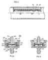
- the drip irrigation line illustrated in Figs. 1-2dcomprises a tube 2 having a plurality of discharge ports 3 spaced along its length, and a flow-reducer element, generally designated 4, fixed to the inner face of the tube at each of the discharge ports.
- Each of the flow-reducer elements 4includes a rigid plastic body constituted of an outer rigid plastic section 5 and an inner rigid plastic section 6; and an elastomeric member 7 fixed within the inner rigid plastic section 6 to define a passageway leading from the interior of the tube 2 to its respective discharge port 3 for reducing the flow through the discharge port.
- This passagewayis automatically enlarged or restricted by the deformation of the elastomeric member 7 in response to the pressure on the opposite faces of the elastomeric member, which in turn is responsive to the flow through the passageway (or pressure within the tube), thereby regulating the flow through the passageway.
- the outer section 5 of the rigid plastic memberis of elongated, generally rectangular configuration having semi-circular ends, and extends for only a fraction of the total circumference of the water supply tube 2. It includes a central partition 51 dividing its interior into an inner elongated cavity 52 and an outer elongated cavity 53. Partition 51 is further formed with an opening 54 at one end, constituting the outlet end of the flow-reducer element, establishing communication between the two cavities 52 and 53. When the flow-reducer element is secured to the inner face of the tube 2, cavity 53 is closed by the inner face of the tube and defines an outlet chamber to the discharge port 3 in the tube.
- the outer cavity 53is circumscribed by a peripheral rib 55 and two transverse end ribs 55a which space partition 51 from the inner face of the tube 2.
- the inner cavity 52is circumscribed by a peripheral skirt 56 formed on its inner edge with an inwardly-extending rib 56a for receiving, with a snap fit, the inner rigid section 6 of the plastic member.
- the outer section 5is further formed with a slot 57 on its inner face adjacent to, and communicating with, its outlet opening 54 through partition 51.
- the inner rigid section 6is of the same outer configuration as the inner cavity 52 of the outer rigid section 5. At one end, constituting the inlet end of the flow-reducer element, section 6 includes a cavity 61 closed by a semi-circular wall 62 formed with a plurality of rectangular openings 63, constituting the inlet openings to the flow-reducer element.
- the inner section 6is further formed with an elongated slot 64 extending from the inlet end of the flow-reducer element and terminating in an enlarged oblong opening 65 at its opposite end.
- the inner section 6is further formed with a rib 66 around its outer periphery enabling the section to be snap-fitted into the outer section 5 by engagement with rib 56a of the outer section.
- the elastomeric element 7has an outer configuration corresponding to slot 64 and oval opening 65 in the inner section 6 of the flow-reducer element.
- elastomeric member 7includes an elongated section 71 fitted within slot 64 of the inner plastic section 6, and an oval section 72 at the end fitted within oval opening 65 of the plastic section 6. As shown particularly in Figs.
- the outer face of elastomeric section 71is planar, but its inner face (i.e., facing the inner face of partition wall 51 in plastic section 5) is formed with embossed ribs 73 defining, with the inner face of partition 51, a flow-reducing passageway or labyrinth 74 between the inlet openings 63 of the flow-reducer element, and the outlet opening 54 leading to the discharge port 3 (Fig. 1) via the outlet chamber 53.
- the end section 72 of the elastomeric member 7is of reduced thickness for its complete area, as compared to the thickness of its section 71.
- the juncture 75 of section 72 with section 71is further reduced in thickness so as to increase the flexibility of section 72 of the elastomeric member.
- the inner face of section 72 of the elastomeric memberis spaced from the inner face of partition 51 by the embossed ribs 73 defining the labyrinth 74, and by annular embossed ribs 73a formed around section 72 on the inner face of the elastomeric member, to thereby define a control chamber 76 in alignment with the outlet opening 54 in partition wall 51 of the rigid plastic section 5.
- the flow-reducer element illustrated in Figs. 1-2doperates as follows: Water from the interior of tube (e.g., 2) flows through inlet opening 63 (e.g., Figs. 2b, 2c), into the flow-reducing passageway 74 defined by the embossed ribs 73 of the elastomeric member 7, then to the control chamber 76 defined by section 72 of the elastomeric member, through outlet opening 54 in partition 51 of the rigid plastic section 5, through outlet chamber 53, and out through the respective discharge port 3.
- This extended flowpath for the waterreduces the pressure of the water flowing through this path so that it exits from the discharge port 3 at substantially atmospheric pressure in the form of a slow trickle or dripping.
- the illustrated flow-reducer elementis self-regulating, tending to maintain a substantially constant discharge rate irrespective of variations in the inlet pressure, terrain, etc.
- the inner face of partition 51is formed with a slot 57 (Fig. 2c) communicating with the outlet opening 54. This has been found to be very desirable in order to maintain communication between the flow passageway 74 and the outlet opening 54 even under high inlet pressures.
- the flow-reducer element illustrated in Figs. 3a and 3bis similarly constructed as described above, except that the slot, corresponding to slot 57 illustrated in Fig. 2c, is formed, not in the rigid plastic section of the flow-reducer element, but rather in the elastomeric element 7.
- the inner face of section 72 of the elastomeric element 7is formed with a slot 77 starting at one end of that section and terminating at the outlet opening 54, to thereby maintain communication between the control chamber 76 and the outlet opening 54 under all pressure conditions.
- the flow-reducer element illustrated in Figs. 3a and 3bis constructed and operates in the same manner as described above.
- Fig. 4illustrates another construction, also generally similar to those described above, except here the elastomeric element, generally designated 107, extends only within the oval cavity 65 formed in the inner rigid section 6.
- the deformable elastomeric member 107is effective only with respect to the control chamber 76 for regulating the outlet flow through the outlet opening 54.
- the elastomeric memberis not formed with the elongated section 71 including the labyrinth-forming ribs 73, but rather the inner plastic section 6 is formed with the labyrinth-forming ribs, as shown at 160 in Fig. 4.
- the flow-reducer element illustrated in Fig. 4is otherwise constructed and operates in the same manner as described above, except that here the flow-regulation is effected only in the control chamber 76 by the deformation of the elastomeric member 107.
- Fig. 5illustrates another type of flow-reducer element, generally designated 204, including a rigid plastic housing constituted of an outer rigid section 205 and an inner rigid section 206, and an embossed elastomeric member 207 which is deformable in response to the pressure on its opposite faces to regulate the flow through the element.
- the outer rigid section 205is formed with a nipple 251, having an opening 252 therethrough, insertable into the respective discharge port of the tube (not shown) such that the opening 252 constitutes the inlet opening from the tube into the flow-reducer element.
- the rigid inner section 206is also formed with a nipple 261 having an opening 262 therethrough, such that opening 262 serves as the outlet opening from the flow-reducer element.
- the inner rigid section 206is further formed with a cavity 263 coaxial with both nipples 251 and 261 and the respective openings 252, 262.
- Cavity 263is of cylindrical configuration
- the elastomeric member 207is embossed with a cylindrical wall 271 fixed within cylindrical cavity 263, and with an elastomeric partition wall 272.
- One side of elastomeric partition wall 272defines an inlet control chamber 273 with the outer rigid section 205 coaxial with the inlet opening 252 passing through nipple 251.
- the opposite side of elastomeric partition wall 272defines an outlet control chamber 274 with the inner rigid section 206 coaxial with the outlet opening 262 through nipple 261.
- the outer face of the inner rigid section 206is further formed with ribs 264 defining, with the inner face of the outer rigid section 205, a flow-reducing passageway or labyrinth 265 communicating, at one end, with the inlet control chamber 273, and at the opposite end with the outlet control chamber 274.
- the outlet control chamber 274is expansible and contractible by the deformation of the partition wall 272 of the elastomeric member 207 to regulate the flow through it and out through the outlet opening 262 in response to flow.
- Any increase in the rate of flowreduces the pressure in the outlet control chamber 274, thereby causing the elastomeric partition wall 272 to deform inwardly, contracting the chamber, and thereby reducing the flow rate.
- the regulationis effected only in the outlet control chamber 274, as in the embodiment of Fig. 4.
- the inner face of the inner rigid section 206is formed with a slot 266 extending to the outlet opening 262.
- Fig. 6illustrates a variation in the construction, wherein the slot (corresponding to 266 in Fig. 5), assuring continuity of flow under high pressure conditions, is formed in the surface of the elastomeric partition 272 within the control chamber 274, as shown at 277, analagous to the construction illustrated in Figs. 3a and 3b.
- the flow-reducer element illustrated in Fig. 6is constructed and operates in the same manner as the flow-reducer element 204 in Fig. 5.
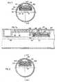
- the drip irrigation emitter illustrated in Figs. 7 and 7ais of the "integrated-tube" type, in that a plurality of such emitters are integrated in a water supply tube, generally designated 302, formed with a plurality of discharge ports 303 spaced along the length of the tube, with the outlet of each emitter communicating with a discharge port of the tube.
- the emitter illustrated in Figs. 7 and 7aincludes a housing formed at one end with an inlet 305 to communicate with the interior of the water supply tube 302, and with a plurality of ribs 306 engageable with the inner face of the tube to define a labyrinth flowpath 307.
- the emitter housingis formed with a cavity 308 communicating with flowpath 307 via an opening 309, and also communicating with the discharge port 303 via an outlet opening 310.
- An embossed elastomeric member 311is fixed within cylindrical cavity 308, and defines an outlet control chamber 312 communicating with the outlet opening 310. The opposite face of the elastomeric member 311 communicates with the interior of the water supply tube 302.
- the embossed elastomeric member 311is integrally formed with an annular rib 309 on its inner face, engageable with the flat inner face 312' of cavity 308, to space the member from the inner face of the cavity and thereby to define the outlet control chamber 312.
- the opposite face of elastomeric member 311is integrally formed with another annular rib 313 which is received within an annular recess 314 formed in that end of the cavity 308.
- annular rib 313is of decreasing thickness towards it outer edge to increase its deformation and thereby to enhance the seal.
- the pressurized water within the water supply tube 302flows from the inlet 305 through the labyrinth flowpath 307 and opening 309, the outlet control chamber 312, outlet 310 and out through the discharge port 303.
- the labyrinth flowpath 307reduces the flow through the discharge port 303, and the embossed elastomeric member 311, by its deformation in response to the difference in pressure on its opposite faces, regulates the flow through the outlet 310 to the discharge port 303.
- the inner face of the cylindrical cavity 308is formed with a radial recess 320 to establish continuous communication with the outlet 310.
- the integrated-tube type emitter illustrated in Figs. 8 and 8ais substantially the same as described above with respect to Figs. 7 and 7a, and therefore the parts have been correspondingly numbered to facilitate understanding.
- the only difference in the construction illustrated in Figs. 2 and 2ais that the cavity, therein designated 308', receiving the embossed elastomeric member 311', is formed with an annular recess 315 on the side of the cavity facing the outlet control chamber 312 for stably fixing the member within the cavity and for producing the seal between the outlet control chamber 312 and the interior of the tube.
- Figs. 9 and 10illustrate the invention as embodied in the "attached" type drip irrigation emitter which includes a nipple formed with the inlet of the emitter and insertable into the discharge port formed in the water supply tube.
- the drip irrigation emitter illustrated in Figs. 9 and 9aincludes a plastic housing constituted of an outer rigid section 325 and an inner rigid section 326.
- the emitterfurther includes an embossed elastomeric member 327 which is deformable in response to the pressure on its opposite faces to regulate the flow through the emitter.
- the outer housing section 325is formed with a nipple 351, having an opening 352 therethrough, insertable into a discharge port of a water supply tube such that the opening 352 constitutes the inlet into the emitter.
- the housing inner section 326is also formed with a nipple 361 having an opening 362 therethrough, constituting the outlet from the emitter.
- the two sections 325, 326are assembled together, with the elastomeric member 327 between them, by snapping an annular bead 326a on the outer face of the side wall of section 326 into an annular recess 325a in the inner face of the side wall of section 325.
- the inner housing section 326is formed with an inner cylindrical cavity 363, and the outer face of section 326 is formed with ribs 364 defining, with the inner face of housing section 325, a labyrinth flowpath 365.
- This flowpath 365communicates, at one end, with an inlet control chamber 373 within cavity 363 on one side of the elastomeric member 327 and communicating with the inlet 352.
- the opposite end of the labyrinth flowpath 365communicates, via an opening 366, with the outlet control chamber 374 on the opposite side of the elastomeric member 327 and communicating with the outlet 362.
- Elastomeric member 327is embossed with integrally formed relief formations on its opposite faces.
- annular rib 380is integrally formed with an annular rib 380 around its periphery engageable with the surface of housing section 326 defining the cavity 363 in order to seal the inner control chamber 373 from the outer control chamber 374.
- annular rib 380is of decreasing thickness towards its outer edge, thereby increasing the deformability of this rib and enhancing the seal produced between its outer edge and the inner surface of housing section 326.
- the outer surface of rib 380is spaced from the inner surface of housing section 325, so as to better permit the outer edge of the rib to deflect firmly against the side wall of the cavity in housing section 326 and thereby to further enhance the seal.
- the relief formation on the opposite face of the embossed elastomeric member 327comprises an annular array of projections 382, extending axially and spaced circumferentially as shown at 383, around member 307. Projections 382 have flat outer faces and engage the underface of housing section 326 to define the outlet control chamber 374.
- Elastomeric member 327will thus be deformed towards and away from the mouth of outlet 362 in response to the difference in pressure in chambers 373 and 374.
- the deformability of the central part of the elastomeric memberis increased by dishing its underface, as shown at 384.
- the underface of housing section 306is formed with a radially-extending recess 390 to maintain communication between the outlet control chamber 374 and outlet 362 even under high inlet pressure conditions when the central dish portion 384 of the elastomeric member 327 may be pressed against the mouth of the outlet 362.
- the emitter illustrated in Figs. 10 and 10ais similarly constructed as in Figs. 3 and 3a, with the following exceptions:
- the embossed elastomeric member 427 clamped between the outer housing section 425 and inner housing section 426is integrally formed on its underface with a second annular rib 490 coaxial with, and of smaller diameter than, the sealing annular rib 480.
- Annular rib 490increases the physical strength of the embossed elastomeric member 427.
- the opposite side of the elastomeric member 427is not formed with the spacing projections (382, in Figs. 9 and 9a), but rather the underface of housing section 426 is formed with these projections, as shown at 487.
- the projectionsare also disposed in an annular array and are circumferentially-spaced, to provide the spaces 489, in order to define the outlet control chamber 474 between the elastomeric member 427 and housing section 426.
Landscapes
- Life Sciences & Earth Sciences (AREA)
- Soil Sciences (AREA)
- Engineering & Computer Science (AREA)
- Water Supply & Treatment (AREA)
- Environmental Sciences (AREA)
- Nozzles (AREA)
- Infusion, Injection, And Reservoir Apparatuses (AREA)
Description
- The present invention relates to drip irrigation emitters and to drip irrigation lines of the type including a continuous tube having a plurality of emitters spaced longitudinally along its length.
- Drip irrigation lines of the foregoing type are gaining widespread use because of their efficiency in the delivery of irrigating water directly to the plant roots, and their substantial savings in the irrigation water required. Such drip irrigation lines generally comprise a tube having a plurality of discharge ports spaced along its length, and a flow-reducer emitters fixed to the tube at each of the discharge ports. In the flow-regulated irrigation line, each of the emitters includes a rigid plastic member and an elastomeric member fixed to the rigid plastic member and definining therewith a flow-reducing passageway communicating with its respective discharge port, which passageway is automatically enlarged or restricted by the deformation of the elastomeric member in response to flow.
- The elastomeric member, in the conventional emitter, is usually in the form of a planar diaphragm, and the rigid plastic member is usually formed with embossments cooperable with the planar diaphragm to define the enlargeable/restrictable flow- reducing passageway regulating the flow to the discharge port. Such a construction has been found to have a number of drawbacks to be referred to below e.g. US-A-4 817 875, FR-A-2 469 959.
- An object of the present invention is to provide a drip irrigation emitter for a drip irrigation line of the foregoing type but modified to produce a number of important advantages as will be described more particularly below.
- According to the present invention, there is provided a drip irrigation emitter comprising a housing including an inlet connectible to a source of pressurized water, an outlet for discharging the water from the housing, a flow-reducer passageway between the inlet and outlet for reducing the flow of water discharged through the outlet, and an elastomeric member fixed within the housing and defining, with an internal surface thereof, at least a part of the flow-reducer passageway which part is automatically enlarged or restricted by deformation of the elastomeric member in response to flow through the at least part of the flow reducer passageway; characterized in that the elastomeric member is embossed with an integrally formed relief formation on the surface thereof facing the internal surface of the housing to space same from the internal surface and to permit the enlargement or reduction of the at least part of the flow-reducer passageway upon the deformation of the elastomeric member in response to the flow.
- It has been found that such a construction provides a number of advantages over the conventional construction. Thus, by providing a shaped or embossed elastomeric member, as distinguished from a planar elastomeric member, it has been found that there is less strain in the elastomeric member during the normal operation of the drip irrigation line, thereby substantially extending the useful life of the line. In addition, by embossing the elastomeric member to define the flow-reducing passageway, a greater proportion of the surface of the flow-reducing passageway is constituted of elastomeric (as distinguished from rigid) material, thereby decreasing the sensitivity of the flow-reducing passageway to clogging. A still further advantage in the novel construction is that flow-reducer elements including embossed elastomeric members are less expensive to manufacture in volume and at low cost, and simpler to produce and to assemble.
- The invention is herein described, by way of example only, with reference to the accompanying drawings, wherein:
- Fig. 1 is a partial longitudinal sectional view of one form of drip irrigation line constructed in accordance with the present invention, Fig. 1a being a transvere section along line a--a of Fig. 1;
- Fig. 2 is a sectional view corresponding to Fig. 1a but illustrating only the flow-reducer element in the drip irrigation line of Fig 1;
- Figs. 2a and 2b are top and bottom views, respectively, of the modified flow-reducer element of Fig. 2, and Figs. 2c and 2d are sectional views along lines c--c of Fig. 2 and d--d of Fig. 2c, respectively;
- Figs. 3a and 3b are views, corresponding to Figs. 2c and 2d, respectively, illustrating a modification in the construction of the flow-reducer element;
- Fig. 4 is a view corresponding to that of Fig. 1 but illustrating a modification in the construction of the flow-reducer element;
- Fig. 5 is a sectional view illustrating a further form of flow-reducer element constructed in accordance with the present invention;
- Fig. 6 illustrates a modification in the construction of the flow-reducer element of Fig. 5;
- Figs. 7 and 8 are transverse sectional views illustrating two forms of "integrated-tube" type drip irrigation emitter constructed in accordance with the present invention, Figs. 7a and 8a being longitudinal sectional views along lines a--a of Figs. 7 and 8, respectively; and
- Figs. 9 and 10 are longitudinal sectional views illustrating two forms of the "attachable" type drip irrigation emitter constructed in accordance with the present invention, Figs. 9a and 10a being transverse sectional views along lines a--a of Figs. 9 and 10, respectively.
- The drip irrigation line illustrated in Figs. 1-2d comprises a
tube 2 having a plurality ofdischarge ports 3 spaced along its length, and a flow-reducer element, generally designated 4, fixed to the inner face of the tube at each of the discharge ports. Each of the flow-reducer elements 4 includes a rigid plastic body constituted of an outer rigidplastic section 5 and an inner rigidplastic section 6; and anelastomeric member 7 fixed within the inner rigidplastic section 6 to define a passageway leading from the interior of thetube 2 to itsrespective discharge port 3 for reducing the flow through the discharge port. This passageway is automatically enlarged or restricted by the deformation of theelastomeric member 7 in response to the pressure on the opposite faces of the elastomeric member, which in turn is responsive to the flow through the passageway (or pressure within the tube), thereby regulating the flow through the passageway. - The
outer section 5 of the rigid plastic member is of elongated, generally rectangular configuration having semi-circular ends, and extends for only a fraction of the total circumference of thewater supply tube 2. It includes acentral partition 51 dividing its interior into an inner elongated cavity 52 and an outerelongated cavity 53.Partition 51 is further formed with anopening 54 at one end, constituting the outlet end of the flow-reducer element, establishing communication between the twocavities 52 and 53. When the flow-reducer element is secured to the inner face of thetube 2,cavity 53 is closed by the inner face of the tube and defines an outlet chamber to thedischarge port 3 in the tube. - The
outer cavity 53 is circumscribed by aperipheral rib 55 and twotransverse end ribs 55a whichspace partition 51 from the inner face of thetube 2. The inner cavity 52 is circumscribed by aperipheral skirt 56 formed on its inner edge with an inwardly-extending rib 56a for receiving, with a snap fit, the innerrigid section 6 of the plastic member. Theouter section 5 is further formed with aslot 57 on its inner face adjacent to, and communicating with, its outlet opening 54 throughpartition 51. - The inner
rigid section 6 is of the same outer configuration as the inner cavity 52 of the outerrigid section 5. At one end, constituting the inlet end of the flow-reducer element,section 6 includes acavity 61 closed by asemi-circular wall 62 formed with a plurality ofrectangular openings 63, constituting the inlet openings to the flow-reducer element. Theinner section 6 is further formed with anelongated slot 64 extending from the inlet end of the flow-reducer element and terminating in an enlargedoblong opening 65 at its opposite end. Theinner section 6 is further formed with arib 66 around its outer periphery enabling the section to be snap-fitted into theouter section 5 by engagement with rib 56a of the outer section. - The
elastomeric element 7 has an outer configuration corresponding toslot 64 andoval opening 65 in theinner section 6 of the flow-reducer element. Thus,elastomeric member 7 includes anelongated section 71 fitted withinslot 64 of the innerplastic section 6, and anoval section 72 at the end fitted withinoval opening 65 of theplastic section 6. As shown particularly in Figs. 1 and 2c, the outer face ofelastomeric section 71 is planar, but its inner face (i.e., facing the inner face ofpartition wall 51 in plastic section 5) is formed with embossedribs 73 defining, with the inner face ofpartition 51, a flow-reducing passageway orlabyrinth 74 between theinlet openings 63 of the flow-reducer element, and the outlet opening 54 leading to the discharge port 3 (Fig. 1) via theoutlet chamber 53. - As shown particularly in Figs. 1 and 2c, the
end section 72 of theelastomeric member 7 is of reduced thickness for its complete area, as compared to the thickness of itssection 71. In addition, thejuncture 75 ofsection 72 withsection 71 is further reduced in thickness so as to increase the flexibility ofsection 72 of the elastomeric member. Further, the inner face ofsection 72 of the elastomeric member is spaced from the inner face ofpartition 51 by the embossedribs 73 defining thelabyrinth 74, and by annular embossedribs 73a formed aroundsection 72 on the inner face of the elastomeric member, to thereby define acontrol chamber 76 in alignment with the outlet opening 54 inpartition wall 51 of the rigidplastic section 5. - The flow-reducer element illustrated in Figs. 1-2d, operates as follows: Water from the interior of tube (e.g., 2) flows through inlet opening 63 (e.g., Figs. 2b, 2c), into the flow-reducing
passageway 74 defined by the embossedribs 73 of theelastomeric member 7, then to thecontrol chamber 76 defined bysection 72 of the elastomeric member, through outlet opening 54 inpartition 51 of the rigidplastic section 5, throughoutlet chamber 53, and out through therespective discharge port 3. This extended flowpath for the water reduces the pressure of the water flowing through this path so that it exits from thedischarge port 3 at substantially atmospheric pressure in the form of a slow trickle or dripping. - If the flow rate through
passageway 74 andcontrol chamber 76 rises, e.g., because of an increase in the inlet pressure, this will reduce the pressure inpassageway 74, and particularly incontrol chamber 76, causing the elastomeric member to deform in the direction of restricting this passageway and control chamber, thereby restricting the outlet flow; similarly, if the flow rate through this passageway and control chamber drops, this will increase the pressure on theelastomeric member 7 tending to enlarge this passageway and control chamber, thereby increasing the flow rate. Accordingly, the illustrated flow-reducer element is self-regulating, tending to maintain a substantially constant discharge rate irrespective of variations in the inlet pressure, terrain, etc. - As indicated earlier, the inner face of
partition 51 is formed with a slot 57 (Fig. 2c) communicating with the outlet opening 54. This has been found to be very desirable in order to maintain communication between theflow passageway 74 and the outlet opening 54 even under high inlet pressures. - The flow-reducer element illustrated in Figs. 3a and 3b is similarly constructed as described above, except that the slot, corresponding to
slot 57 illustrated in Fig. 2c, is formed, not in the rigid plastic section of the flow-reducer element, but rather in theelastomeric element 7. Thus, as shown in Figs. 3a and 3b, the inner face ofsection 72 of theelastomeric element 7 is formed with aslot 77 starting at one end of that section and terminating at the outlet opening 54, to thereby maintain communication between thecontrol chamber 76 and the outlet opening 54 under all pressure conditions. In all other respects, the flow-reducer element illustrated in Figs. 3a and 3b is constructed and operates in the same manner as described above. - Fig. 4 illustrates another construction, also generally similar to those described above, except here the elastomeric element, generally designated 107, extends only within the
oval cavity 65 formed in the innerrigid section 6. Thus, the deformableelastomeric member 107 is effective only with respect to thecontrol chamber 76 for regulating the outlet flow through theoutlet opening 54. The elastomeric member is not formed with theelongated section 71 including the labyrinth-formingribs 73, but rather the innerplastic section 6 is formed with the labyrinth-forming ribs, as shown at 160 in Fig. 4. The flow-reducer element illustrated in Fig. 4 is otherwise constructed and operates in the same manner as described above, except that here the flow-regulation is effected only in thecontrol chamber 76 by the deformation of theelastomeric member 107. - Fig. 5 illustrates another type of flow-reducer element, generally designated 204, including a rigid plastic housing constituted of an outer
rigid section 205 and an innerrigid section 206, and an embossedelastomeric member 207 which is deformable in response to the pressure on its opposite faces to regulate the flow through the element. In this case, the outerrigid section 205 is formed with anipple 251, having anopening 252 therethrough, insertable into the respective discharge port of the tube (not shown) such that theopening 252 constitutes the inlet opening from the tube into the flow-reducer element. The rigidinner section 206 is also formed with anipple 261 having anopening 262 therethrough, such thatopening 262 serves as the outlet opening from the flow-reducer element. - The inner
rigid section 206 is further formed with acavity 263 coaxial with bothnipples respective openings Cavity 263 is of cylindrical configuration, and theelastomeric member 207 is embossed with acylindrical wall 271 fixed withincylindrical cavity 263, and with anelastomeric partition wall 272. One side ofelastomeric partition wall 272 defines aninlet control chamber 273 with the outerrigid section 205 coaxial with the inlet opening 252 passing throughnipple 251. The opposite side ofelastomeric partition wall 272 defines anoutlet control chamber 274 with the innerrigid section 206 coaxial with theoutlet opening 262 throughnipple 261. - In addition, the outer face of the inner
rigid section 206 is further formed withribs 264 defining, with the inner face of the outerrigid section 205, a flow-reducing passageway orlabyrinth 265 communicating, at one end, with theinlet control chamber 273, and at the opposite end with theoutlet control chamber 274. Theoutlet control chamber 274 is expansible and contractible by the deformation of thepartition wall 272 of theelastomeric member 207 to regulate the flow through it and out through the outlet opening 262 in response to flow. - Accordingly, the water inletted from the water supply tube (not shown) via inlet opening 252 through
nipple 251 flows through theinlet control chamber 273, thepassageway 265 between the outer face of the innerrigid section 206 and the inner face of the outerrigid section 205, theoutlet control chamber 274, and out through the outlet opening 262 innipple 261. Any increase in the rate of flow reduces the pressure in theoutlet control chamber 274, thereby causing theelastomeric partition wall 272 to deform inwardly, contracting the chamber, and thereby reducing the flow rate. Thus, in the embodiment illustrated in Fig. 5, the regulation is effected only in theoutlet control chamber 274, as in the embodiment of Fig. 4. - In order to assure continuity of flow through the
outlet opening 262 even high under high pressure conditions, the inner face of the innerrigid section 206, defining one side of thecontrol chamber 274, is formed with aslot 266 extending to theoutlet opening 262. - Fig. 6 illustrates a variation in the construction, wherein the slot (corresponding to 266 in Fig. 5), assuring continuity of flow under high pressure conditions, is formed in the surface of the
elastomeric partition 272 within thecontrol chamber 274, as shown at 277, analagous to the construction illustrated in Figs. 3a and 3b. In all other respects, the flow-reducer element illustrated in Fig. 6 is constructed and operates in the same manner as the flow-reducer element 204 in Fig. 5. - The drip irrigation emitter illustrated in Figs. 7 and 7a is of the "integrated-tube" type, in that a plurality of such emitters are integrated in a water supply tube, generally designated 302, formed with a plurality of
discharge ports 303 spaced along the length of the tube, with the outlet of each emitter communicating with a discharge port of the tube. - The emitter illustrated in Figs. 7 and 7a includes a housing formed at one end with an
inlet 305 to communicate with the interior of thewater supply tube 302, and with a plurality ofribs 306 engageable with the inner face of the tube to define alabyrinth flowpath 307. At the outlet end offlowpath 307, the emitter housing is formed with acavity 308 communicating withflowpath 307 via anopening 309, and also communicating with thedischarge port 303 via anoutlet opening 310. An embossedelastomeric member 311 is fixed withincylindrical cavity 308, and defines anoutlet control chamber 312 communicating with theoutlet opening 310. The opposite face of theelastomeric member 311 communicates with the interior of thewater supply tube 302. - The embossed
elastomeric member 311 is integrally formed with anannular rib 309 on its inner face, engageable with the flat inner face 312' ofcavity 308, to space the member from the inner face of the cavity and thereby to define theoutlet control chamber 312. The opposite face ofelastomeric member 311 is integrally formed with anotherannular rib 313 which is received within anannular recess 314 formed in that end of thecavity 308. - It will be seen that the pressure within the
water supply tube 302 will be applied torib 313 to deflect it firmly against the side wall ofcavity 308, and thereby to seal the outlet control chamber from the interior of thewater supply tube 302. For this purpose,annular rib 313 is of decreasing thickness towards it outer edge to increase its deformation and thereby to enhance the seal. - The operation of the emitter illustrated in Figs. 7 and 7a will be apparent from the above description. Thus, the pressurized water within the
water supply tube 302 flows from theinlet 305 through the labyrinth flowpath 307 andopening 309, theoutlet control chamber 312,outlet 310 and out through thedischarge port 303. The labyrinth flowpath 307 reduces the flow through thedischarge port 303, and the embossedelastomeric member 311, by its deformation in response to the difference in pressure on its opposite faces, regulates the flow through theoutlet 310 to thedischarge port 303. Preferably, the inner face of thecylindrical cavity 308 is formed with aradial recess 320 to establish continuous communication with theoutlet 310. - The integrated-tube type emitter illustrated in Figs. 8 and 8a is substantially the same as described above with respect to Figs. 7 and 7a, and therefore the parts have been correspondingly numbered to facilitate understanding. The only difference in the construction illustrated in Figs. 2 and 2a is that the cavity, therein designated 308', receiving the embossed elastomeric member 311', is formed with an
annular recess 315 on the side of the cavity facing theoutlet control chamber 312 for stably fixing the member within the cavity and for producing the seal between theoutlet control chamber 312 and the interior of the tube. - In all other respects, the construction and operation of the emitter illustrated in Figs. 8 and 8a are the same as described above with respect to Figs. 7 and 7a.
- Figs. 9 and 10 illustrate the invention as embodied in the "attached" type drip irrigation emitter which includes a nipple formed with the inlet of the emitter and insertable into the discharge port formed in the water supply tube.
- The drip irrigation emitter illustrated in Figs. 9 and 9a includes a plastic housing constituted of an outer
rigid section 325 and an innerrigid section 326. The emitter further includes an embossedelastomeric member 327 which is deformable in response to the pressure on its opposite faces to regulate the flow through the emitter. Theouter housing section 325 is formed with anipple 351, having anopening 352 therethrough, insertable into a discharge port of a water supply tube such that theopening 352 constitutes the inlet into the emitter. The housinginner section 326 is also formed with anipple 361 having anopening 362 therethrough, constituting the outlet from the emitter. The twosections elastomeric member 327 between them, by snapping anannular bead 326a on the outer face of the side wall ofsection 326 into anannular recess 325a in the inner face of the side wall ofsection 325. - The
inner housing section 326 is formed with an innercylindrical cavity 363, and the outer face ofsection 326 is formed withribs 364 defining, with the inner face ofhousing section 325, alabyrinth flowpath 365. Thisflowpath 365 communicates, at one end, with aninlet control chamber 373 withincavity 363 on one side of theelastomeric member 327 and communicating with theinlet 352. The opposite end of thelabyrinth flowpath 365 communicates, via anopening 366, with theoutlet control chamber 374 on the opposite side of theelastomeric member 327 and communicating with theoutlet 362. Elastomeric member 327 is embossed with integrally formed relief formations on its opposite faces.- Thus, on the face within the
inlet control chamber 373,elastomeric member 327 is integrally formed with anannular rib 380 around its periphery engageable with the surface ofhousing section 326 defining thecavity 363 in order to seal theinner control chamber 373 from theouter control chamber 374. As clearly seen in Fig. 9,annular rib 380 is of decreasing thickness towards its outer edge, thereby increasing the deformability of this rib and enhancing the seal produced between its outer edge and the inner surface ofhousing section 326. In addition, the outer surface ofrib 380 is spaced from the inner surface ofhousing section 325, so as to better permit the outer edge of the rib to deflect firmly against the side wall of the cavity inhousing section 326 and thereby to further enhance the seal. - The relief formation on the opposite face of the embossed
elastomeric member 327 comprises an annular array ofprojections 382, extending axially and spaced circumferentially as shown at 383, aroundmember 307.Projections 382 have flat outer faces and engage the underface ofhousing section 326 to define theoutlet control chamber 374. Elastomeric member 327 will thus be deformed towards and away from the mouth ofoutlet 362 in response to the difference in pressure inchambers housing section 306 is formed with a radially-extendingrecess 390 to maintain communication between theoutlet control chamber 374 andoutlet 362 even under high inlet pressure conditions when thecentral dish portion 384 of theelastomeric member 327 may be pressed against the mouth of theoutlet 362.- When the emitter of Figs. 9 and 9a is applied to a discharge port of a water supply tube (not shown), by inserting
nipple 351 into the water discharge port, pressurized water passes from the interior of the water supply tube viainlet 352 through theinlet control chamber 373, thelabyrinth flowpath 365, opening 366,outlet control chamber 374, and out through theoutlet 362. Thecentral dish portion 384 of theelastomeric member 327 will be deformed towards or away fromoutlet 362 in response to the difference in pressure at its opposite sides facing theinlet control chamber 373 andoutlet control chamber 374, respectively. Thus, if the flow through theoutlet control chamber 374 is too high, this will decrease the pressure on that face of theelastomeric member 327, and will therefore cause it to deflect towardsoutlet 362, which will automatically reduce the flow rate; whereas if the flow rate is too low, this will increase the pressure withinchamber 374 to deflectelastomeric member 327 away fromoutlet 362, thereby increasing the flow rate. - The emitter illustrated in Figs. 10 and 10a is similarly constructed as in Figs. 3 and 3a, with the following exceptions:
The embossedelastomeric member 427 clamped between theouter housing section 425 andinner housing section 426 is integrally formed on its underface with a secondannular rib 490 coaxial with, and of smaller diameter than, the sealingannular rib 480.Annular rib 490 increases the physical strength of the embossedelastomeric member 427. - In addition, the opposite side of the
elastomeric member 427 is not formed with the spacing projections (382, in Figs. 9 and 9a), but rather the underface ofhousing section 426 is formed with these projections, as shown at 487. The projections are also disposed in an annular array and are circumferentially-spaced, to provide thespaces 489, in order to define theoutlet control chamber 474 between theelastomeric member 427 andhousing section 426. - In all other respects, the structure and operation of the emitter illustrated in Figs. 10 and 10a are the same as described above with respect to Figs. 9 and 9a. Thus, the deformation of the central part of the
elastomeric member 427, in response to the difference in pressure in theinlet control chamber 473 andoutlet control chamber 474, will automatically move the central part of the elastomeric member towards or away from theoutlet 462 to maintain a relatively constant rate of flow of the water from theinlet 452,inlet control chamber 473,labyrinth flowpath 465,outlet control chamber 474, andoutlet 462. - While the above drawings illustrate the emitter as extending for a small part of the circumference of the water supply tube, it will be appreciated that such emitters could extend for a major part or for the complete circumference of the water supply tube. Other variations and applications of the invention will be apparent.
- Where technical features mentioned in any claim are followed by reference signs, those reference signs have been included for the sole purpose of increasing the intelligibility of the claims and accordingly, such reference signs do not have any limiting effect on the scope of each element identified by way of example by such reference signs.
Claims (11)
- A drip irrigation emitter comprising a housing including an inlet connectible to a source of pressurized water, an outlet for discharging the water from the housing, a flow-reducer passageway between said inlet and outlet for reducing the flow of water discharged through the outlet, and an elastomeric member fixed within the housing and defining, with an internal surface thereof, at least a part of said flow-reducer passageway which part is automatically enlarged or restricted by deformation of the elastomeric member in response to flow through said at least part of the flow reducer passageway; characterized in that said elastomeric member is embossed with an integrally formed relief formation on the surface thereof facing said internal surface of the housing to space same from said internal surface and to permit the enlargement or reduction of said at least part of the flow-reducer passageway upon the deformation of the elastomeric member in response to said flow.
- The emitter according to Claim 1, wherein said flow-reducer passageway includes a labyrinth flow path communicating with said inlet, and an outlet control chamber between said labyrinth flow path and said outlet, said embossed elastomeric member defining a deformable wall of at least said outlet control chamber.
- The emitter according to Claim 1, wherein said relief formation integrally formed in said embossed elastomeric member includes a plurality of ribs engageable with said internal surface of the housing and defining therewith said labyrinth flow path.
- The emitter according to Claim 1, wherein said relief formation integrally formed in said embossed elastomeric member includes an annular rib engageable with said internal surface of the housing and defining therewith said outlet control chamber.
- The emitter according to any one of Claims 1-4, wherein said housing is fixable to a water supply tube having a discharge port, with said inlet of the housing communicating with the interior of the water supply tube, and the outlet of the housing communicating with said discharge port.
- The emitter according to Claim 5, wherein said housing is formed with a cavity communicating with said outlet, said embossed elastomeric member being fixed within said cavity to define on one side thereof, an outlet control chamber communicating with said discharge port via said outlet of the housing, the opposite side of said embossed elastomeric member communicating with the interior of the water supply tube.
- The emitter according to Claim 6, wherein said relief formation on the embossed elastomeric member includes an annular rib formed around the periphery of the embossed elastomeric member on said opposite surface and deflectable firmly against the side wall of the cavity in order to seal the outlet control chamber from the interior of said water supply tube.
- The emitter according to Claim 7, wherein said side wall of the cavity is formed with an annular recess in the end thereof facing the interior of said water supply tube, said annular rib of the embossed elastomeric member being seated in said annular recess.
- The emitter according to Claim 7, wherein said side wall of the cavity is formed with an annular recess in the end thereof facing said outlet control chamber; said embossed elastomeric member being formed with a second annular rib, on the face thereof opposite to that of said first-mentioned annular rib, which second annular rib is seated in said annular recess.
- The emitter according to any one of Claims 1-9, wherein said housing is fixed to the inner face of a water supply tube and is further formed with ribs engageable with said inner face to define a labyrinth flowpath communicating at one end with said inlet, and at the opposite end with said outlet via said outlet control chamber.
- The emitter according to any one of Claims 1-9, wherein said housing includes a nipple formed with said inlet and insertable into a discharge port formed in a water supply tube.
Applications Claiming Priority (4)
| Application Number | Priority Date | Filing Date | Title |
|---|---|---|---|
| IL95138 | 1990-07-20 | ||
| IL95138AIL95138A (en) | 1990-07-20 | 1990-07-20 | Drip irrigation lines |
| IL9096164AIL96164A0 (en) | 1990-07-19 | 1990-10-29 | Drip irrigation emitter |
| IL96164 | 1990-10-29 |
Publications (3)
| Publication Number | Publication Date |
|---|---|
| EP0467386A2 EP0467386A2 (en) | 1992-01-22 |
| EP0467386A3 EP0467386A3 (en) | 1992-05-27 |
| EP0467386B1true EP0467386B1 (en) | 1994-08-31 |
Family
ID=26322114
Family Applications (1)
| Application Number | Title | Priority Date | Filing Date |
|---|---|---|---|
| EP91112110AExpired - LifetimeEP0467386B1 (en) | 1990-07-20 | 1991-07-19 | Drip irrigation emitters |
Country Status (5)
| Country | Link |
|---|---|
| US (1) | US5183208A (en) |
| EP (1) | EP0467386B1 (en) |
| AU (1) | AU651356B2 (en) |
| DE (1) | DE69103704T2 (en) |
| ES (1) | ES2058998T3 (en) |
Families Citing this family (60)
| Publication number | Priority date | Publication date | Assignee | Title |
|---|---|---|---|---|
| IL100749A (en)* | 1992-01-24 | 1996-01-31 | Plastro Gvat | Regulated drip irrigation emitter with improved membrane |
| US5333793A (en)* | 1993-07-21 | 1994-08-02 | T-Systems International, Inc. | Drip irrigation hose with pressure compensation and method for its manufacture |
| US5400973A (en)* | 1993-07-30 | 1995-03-28 | Cohen; Amir | Pressure responsive regulated flow restrictor useful for drip irrigation |
| US5634594A (en)* | 1993-07-30 | 1997-06-03 | Cohen; Amir | Flow control device particularly useful in drip irrigation emitters |
| FR2709400B1 (en)* | 1993-09-01 | 1995-12-15 | Pierre Jouglens | Drip device for crop irrigation system. |
| IL108171A (en)* | 1993-12-24 | 2000-01-31 | Hydromatic Ltd | Flow reducer devices and drip irrigation emitter including same |
| US5628462A (en)* | 1995-08-15 | 1997-05-13 | Miller; David B. | Drip irrigation emitter |
| US5688072A (en)* | 1995-12-14 | 1997-11-18 | Micro Irrigation Technologies, Inc. | Agricultural drip tape |
| ES2137825B1 (en)* | 1996-02-16 | 2000-08-16 | Twin Drops Iberica S A | SELF-COMPENSATING AND ANTI-DISCHARGE DRIPPER FOR UNIFORM IRRIGATIONS. |
| IL117326A (en)* | 1996-03-01 | 1999-11-30 | Cohen Amir | Regulated flow-restrictor devices particularly useful in drip irrigation |
| IL121967A (en)* | 1997-10-14 | 2001-06-14 | Hydro Plan Eng Ltd | Emitter unit |
| IL122777A (en)* | 1997-12-28 | 2003-12-10 | Amir Cohen | Valve controlled drip irrigation lines |
| US6213408B1 (en) | 1999-11-18 | 2001-04-10 | Eureka Technologies Ltd | Flow regulator and corresponding method with pressure responsive flow regulation |
| GR1003833B (en)* | 1999-12-08 | 2002-03-07 | Irrigation emitter with self-adjustment of the water pressure | |
| US6886761B2 (en) | 2000-08-21 | 2005-05-03 | Amir Cohen | Drip irrigation hose and method and apparatus for making same |
| US6736337B2 (en) | 2002-02-08 | 2004-05-18 | The Toro Company | Pressure compensating drip irrigation hose |
| WO2005115634A1 (en) | 2004-05-24 | 2005-12-08 | Amir Cohen | Drip irrigation hose and method for making same |
| US8302887B2 (en) | 2005-03-31 | 2012-11-06 | Rain Bird Corporation | Drip emitter |
| US20070189852A1 (en)* | 2006-01-31 | 2007-08-16 | Greg Wolfley | Modular network irrigation system |
| US7648085B2 (en)* | 2006-02-22 | 2010-01-19 | Rain Bird Corporation | Drip emitter |
| ES2328541B1 (en)* | 2006-11-08 | 2010-09-22 | Wind, S.L. | MANUFACTURING PROCESS OF AN ISSUER FOR DRIP IRRIGATION. |
| USD618305S1 (en) | 2008-12-31 | 2010-06-22 | Rain Bird Corporation | Low flow irrigation emitter |
| US8628032B2 (en)* | 2008-12-31 | 2014-01-14 | Rain Bird Corporation | Low flow irrigation emitter |
| US8439282B2 (en)* | 2009-02-06 | 2013-05-14 | Rain Bird Corporation | Low flow irrigation emitter |
| USD615151S1 (en) | 2009-02-06 | 2010-05-04 | Rain Bird Corporation | Low flow irrigation emitter |
| US8317111B2 (en)* | 2010-01-31 | 2012-11-27 | Amirim Products Development & Patents Ltd. | Bi-component drip emitter |
| GB2484924A (en) | 2010-10-25 | 2012-05-02 | Amirim Products Dev & Patents Ltd | An on line drip irrigation emitter having an inlet filtering dvice |
| IL212105A (en) | 2011-04-03 | 2016-07-31 | Einav Zvi | Integral dripper with an elongated exit pool |
| US8511586B2 (en) | 2011-04-20 | 2013-08-20 | Deere & Company | Disc shaped regulated drip irrigation emitter |
| US9485923B2 (en) | 2012-03-26 | 2016-11-08 | Rain Bird Corporation | Elastomeric emitter and methods relating to same |
| US9877440B2 (en) | 2012-03-26 | 2018-01-30 | Rain Bird Corporation | Elastomeric emitter and methods relating to same |
| US20130248622A1 (en) | 2012-03-26 | 2013-09-26 | Jae Yung Kim | Drip line and emitter and methods relating to same |
| US10440903B2 (en) | 2012-03-26 | 2019-10-15 | Rain Bird Corporation | Drip line emitter and methods relating to same |
| JP6180410B2 (en)* | 2012-05-24 | 2017-08-16 | 株式会社エンプラス | Drip irrigation dripper and drip irrigation apparatus provided with the same |
| IL221089A (en)* | 2012-07-24 | 2016-05-31 | Einav Zvi | Integral dropper with easy paddling exit pool |
| ES2650374T3 (en)* | 2012-09-28 | 2018-01-18 | Enplas Corporation | Dropper for drip irrigation and drip irrigation device |
| US9872444B2 (en) | 2013-03-15 | 2018-01-23 | Rain Bird Corporation | Drip emitter |
| US9462760B2 (en) | 2013-07-09 | 2016-10-11 | Amirim Products Development & Patents Ltd. | In line button drip emitter |
| US9949448B2 (en)* | 2015-01-14 | 2018-04-24 | Amirim Products Development & Patents Ltd. | Modular in line button drip emitter system |
| US10869434B2 (en) | 2013-07-09 | 2020-12-22 | Amirim Products Development & Patents Ltd. | Elliptical in line button dripper with extended bonding zones |
| USD811179S1 (en) | 2013-08-12 | 2018-02-27 | Rain Bird Corporation | Emitter part |
| US10631473B2 (en) | 2013-08-12 | 2020-04-28 | Rain Bird Corporation | Elastomeric emitter and methods relating to same |
| US10285342B2 (en) | 2013-08-12 | 2019-05-14 | Rain Bird Corporation | Elastomeric emitter and methods relating to same |
| JP6339338B2 (en) | 2013-08-26 | 2018-06-06 | 株式会社エンプラス | Dripper and drip irrigation tube |
| US9883640B2 (en) | 2013-10-22 | 2018-02-06 | Rain Bird Corporation | Methods and apparatus for transporting elastomeric emitters and/or manufacturing drip lines |
| US10327396B2 (en) | 2013-12-27 | 2019-06-25 | Enplas Corporation | Emitter, and drip irrigation tube |
| US10330559B2 (en) | 2014-09-11 | 2019-06-25 | Rain Bird Corporation | Methods and apparatus for checking emitter bonds in an irrigation drip line |
| WO2017046686A1 (en)* | 2015-09-17 | 2017-03-23 | Netafim Ltd | A drip emitter and a membrane for a drip emitter |
| JP6689634B2 (en)* | 2016-03-17 | 2020-04-28 | 株式会社エンプラス | Emitter and drip irrigation tubes |
| US10299444B2 (en) | 2016-04-07 | 2019-05-28 | Amir Cohen | In line button drip emitter |
| US10375904B2 (en) | 2016-07-18 | 2019-08-13 | Rain Bird Corporation | Emitter locating system and related methods |
| US11051466B2 (en) | 2017-01-27 | 2021-07-06 | Rain Bird Corporation | Pressure compensation members, emitters, drip line and methods relating to same |
| US10626998B2 (en) | 2017-05-15 | 2020-04-21 | Rain Bird Corporation | Drip emitter with check valve |
| CN107821106B (en)* | 2017-09-28 | 2023-06-09 | 大禹节水(天津)有限公司 | Pressure compensation type water dropper for drip irrigation |
| US11793127B2 (en) | 2017-12-12 | 2023-10-24 | Netafim, Ltd. | Drip emitter having membrane with a non-planar portion protruding into regulating chamber recess |
| USD883048S1 (en) | 2017-12-12 | 2020-05-05 | Rain Bird Corporation | Emitter part |
| US11317571B2 (en)* | 2018-01-23 | 2022-05-03 | Emplas Corporation | Emitter and drip irrigation tube |
| US11985924B2 (en) | 2018-06-11 | 2024-05-21 | Rain Bird Corporation | Emitter outlet, emitter, drip line and methods relating to same |
| CN112189538A (en)* | 2020-09-30 | 2021-01-08 | 萧县年年养鱼农民专业合作社 | Water-saving irrigation equipment for fruit and vegetable planting |
| US12207599B2 (en) | 2021-10-12 | 2025-01-28 | Rain Bird Corporation | Emitter coupler and irrigation system |
Family Cites Families (8)
| Publication number | Priority date | Publication date | Assignee | Title |
|---|---|---|---|---|
| US3998427A (en)* | 1975-12-11 | 1976-12-21 | Clarence Bentley | Self-cleaning drip irrigation valve |
| IL50650A (en)* | 1976-10-10 | 1979-05-31 | Drori Mordeki | Regulated flow-reducing device particularly useful for drip irrigation |
| US4573640A (en)* | 1976-10-26 | 1986-03-04 | Hydro-Plan Engineering Ltd. | Irrigation emitter unit |
| IL58773A (en)* | 1979-11-22 | 1982-12-31 | Hydro Plan Eng Ltd | Emitter unit |
| NZ200960A (en)* | 1981-06-22 | 1985-11-08 | Ris Irrigation Syst | Drip feed device containing disc with tortuous flow paths on each side |
| AU8708382A (en)* | 1981-08-25 | 1983-05-12 | Wannan, I.R. | Drip irrigator |
| US4817875A (en)* | 1987-09-21 | 1989-04-04 | David Karmeli | Flexible pipe for trickle irrigation |
| IL93255A (en)* | 1990-02-02 | 1997-03-18 | Plastro Gvat | Drip irrigation lines |
- 1991
- 1991-07-15USUS07/729,953patent/US5183208A/ennot_activeExpired - Lifetime
- 1991-07-18AUAU81107/91Apatent/AU651356B2/ennot_activeCeased
- 1991-07-19DEDE69103704Tpatent/DE69103704T2/ennot_activeExpired - Fee Related
- 1991-07-19ESES91112110Tpatent/ES2058998T3/ennot_activeExpired - Lifetime
- 1991-07-19EPEP91112110Apatent/EP0467386B1/ennot_activeExpired - Lifetime
Also Published As
| Publication number | Publication date |
|---|---|
| AU651356B2 (en) | 1994-07-21 |
| ES2058998T3 (en) | 1994-11-01 |
| EP0467386A3 (en) | 1992-05-27 |
| EP0467386A2 (en) | 1992-01-22 |
| DE69103704D1 (en) | 1994-10-06 |
| DE69103704T2 (en) | 1994-12-22 |
| US5183208A (en) | 1993-02-02 |
| AU8110791A (en) | 1992-01-23 |
Similar Documents
| Publication | Publication Date | Title |
|---|---|---|
| EP0467386B1 (en) | Drip irrigation emitters | |
| US5294058A (en) | Regulated drip irrigation emitter | |
| US5586727A (en) | Flow reducer devices and drip irrigation emitter including same | |
| EP0636309B1 (en) | Regulated flow restrictor device particularly useful as a drip irrigation emitter | |
| US10455780B2 (en) | In line button drip emitter | |
| EP0444425B1 (en) | Drip irrigation lines | |
| US4105162A (en) | Regulated flow-reducing device particularly useful for drip irrigation | |
| US4687143A (en) | Drip irrigation apparatus | |
| EP1435196B1 (en) | An improved irrigation emitter unit | |
| EP0268418B1 (en) | Flow regulating device | |
| US4502631A (en) | Trickle irrigation unit | |
| US5636797A (en) | Drip irrigation emitter and flow control unit included therein | |
| EP0791290B1 (en) | Regulated flow-restrictor device for drip irrigation | |
| US4366926A (en) | Irrigation emitter unit | |
| US3767124A (en) | Self-flushing irrigating valve | |
| US4846406A (en) | Micro flow control valve for irrigation systems and method | |
| EP0343789B1 (en) | Elastomeric flow control pin for irrigation systems | |
| IL97564A (en) | Drip irrigation apparatus | |
| USRE29022E (en) | Self-flushing irrigation valve | |
| US4909441A (en) | Elastomeric flow control valve | |
| US4971253A (en) | Pressure compensating emitters for drip irrigation systems | |
| US4715543A (en) | Flow restrictor device particularly useful for drip irrigation | |
| US10869434B2 (en) | Elliptical in line button dripper with extended bonding zones | |
| EP0414977A2 (en) | Microsprayers for irrigation | |
| NZ230693A (en) | Elastomeric pressure-modulated flow control valve |
Legal Events
| Date | Code | Title | Description |
|---|---|---|---|
| PUAI | Public reference made under article 153(3) epc to a published international application that has entered the european phase | Free format text:ORIGINAL CODE: 0009012 | |
| AK | Designated contracting states | Kind code of ref document:A2 Designated state(s):DE ES FR GR IT NL | |
| PUAL | Search report despatched | Free format text:ORIGINAL CODE: 0009013 | |
| AK | Designated contracting states | Kind code of ref document:A3 Designated state(s):DE ES FR GR IT NL | |
| 17P | Request for examination filed | Effective date:19921117 | |
| 17Q | First examination report despatched | Effective date:19931119 | |
| GRAA | (expected) grant | Free format text:ORIGINAL CODE: 0009210 | |
| AK | Designated contracting states | Kind code of ref document:B1 Designated state(s):DE ES FR GR IT NL | |
| REF | Corresponds to: | Ref document number:69103704 Country of ref document:DE Date of ref document:19941006 | |
| ITF | It: translation for a ep patent filed | ||
| ET | Fr: translation filed | ||
| REG | Reference to a national code | Ref country code:GR Ref legal event code:FG4A Free format text:3013909 | |
| PLBE | No opposition filed within time limit | Free format text:ORIGINAL CODE: 0009261 | |
| STAA | Information on the status of an ep patent application or granted ep patent | Free format text:STATUS: NO OPPOSITION FILED WITHIN TIME LIMIT | |
| 26N | No opposition filed | ||
| NLS | Nl: assignments of ep-patents | Owner name:PLASTRO GVAT | |
| REG | Reference to a national code | Ref country code:FR Ref legal event code:TP | |
| REG | Reference to a national code | Ref country code:ES Ref legal event code:PC2A Owner name:PLASTRO GVAT | |
| PGFP | Annual fee paid to national office [announced via postgrant information from national office to epo] | Ref country code:FR Payment date:19970624 Year of fee payment:7 | |
| PGFP | Annual fee paid to national office [announced via postgrant information from national office to epo] | Ref country code:NL Payment date:19970630 Year of fee payment:7 | |
| PGFP | Annual fee paid to national office [announced via postgrant information from national office to epo] | Ref country code:DE Payment date:19970702 Year of fee payment:7 | |
| PGFP | Annual fee paid to national office [announced via postgrant information from national office to epo] | Ref country code:ES Payment date:19970718 Year of fee payment:7 | |
| PGFP | Annual fee paid to national office [announced via postgrant information from national office to epo] | Ref country code:GR Payment date:19970731 Year of fee payment:7 | |
| PG25 | Lapsed in a contracting state [announced via postgrant information from national office to epo] | Ref country code:ES Free format text:LAPSE BECAUSE OF THE APPLICANT RENOUNCES Effective date:19980720 | |
| PG25 | Lapsed in a contracting state [announced via postgrant information from national office to epo] | Ref country code:GR Free format text:LAPSE BECAUSE OF NON-PAYMENT OF DUE FEES Effective date:19980731 | |
| PG25 | Lapsed in a contracting state [announced via postgrant information from national office to epo] | Ref country code:NL Free format text:LAPSE BECAUSE OF NON-PAYMENT OF DUE FEES Effective date:19990201 | |
| PG25 | Lapsed in a contracting state [announced via postgrant information from national office to epo] | Ref country code:FR Free format text:LAPSE BECAUSE OF NON-PAYMENT OF DUE FEES Effective date:19990331 | |
| NLV4 | Nl: lapsed or anulled due to non-payment of the annual fee | Effective date:19990201 | |
| PG25 | Lapsed in a contracting state [announced via postgrant information from national office to epo] | Ref country code:DE Free format text:LAPSE BECAUSE OF NON-PAYMENT OF DUE FEES Effective date:19990501 | |
| REG | Reference to a national code | Ref country code:FR Ref legal event code:ST | |
| REG | Reference to a national code | Ref country code:ES Ref legal event code:FD2A Effective date:20001009 | |
| PG25 | Lapsed in a contracting state [announced via postgrant information from national office to epo] | Ref country code:IT Free format text:LAPSE BECAUSE OF NON-PAYMENT OF DUE FEES Effective date:20050719 |