EP0466638A1 - Femoral head prosthesis - Google Patents
Femoral head prosthesisDownload PDFInfo
- Publication number
- EP0466638A1 EP0466638A1EP91810444AEP91810444AEP0466638A1EP 0466638 A1EP0466638 A1EP 0466638A1EP 91810444 AEP91810444 AEP 91810444AEP 91810444 AEP91810444 AEP 91810444AEP 0466638 A1EP0466638 A1EP 0466638A1
- Authority
- EP
- European Patent Office
- Prior art keywords
- wire mesh
- shaft body
- cavities
- bone tissue
- femoral head
- Prior art date
- Legal status (The legal status is an assumption and is not a legal conclusion. Google has not performed a legal analysis and makes no representation as to the accuracy of the status listed.)
- Withdrawn
Links
Images
Classifications
- A—HUMAN NECESSITIES
- A61—MEDICAL OR VETERINARY SCIENCE; HYGIENE
- A61F—FILTERS IMPLANTABLE INTO BLOOD VESSELS; PROSTHESES; DEVICES PROVIDING PATENCY TO, OR PREVENTING COLLAPSING OF, TUBULAR STRUCTURES OF THE BODY, e.g. STENTS; ORTHOPAEDIC, NURSING OR CONTRACEPTIVE DEVICES; FOMENTATION; TREATMENT OR PROTECTION OF EYES OR EARS; BANDAGES, DRESSINGS OR ABSORBENT PADS; FIRST-AID KITS
- A61F2/00—Filters implantable into blood vessels; Prostheses, i.e. artificial substitutes or replacements for parts of the body; Appliances for connecting them with the body; Devices providing patency to, or preventing collapsing of, tubular structures of the body, e.g. stents
- A61F2/02—Prostheses implantable into the body
- A61F2/30—Joints
- A61F2/32—Joints for the hip
- A61F2/36—Femoral heads ; Femoral endoprostheses
- A61F2/3662—Femoral shafts
- A61F2/367—Proximal or metaphyseal parts of shafts
- A—HUMAN NECESSITIES
- A61—MEDICAL OR VETERINARY SCIENCE; HYGIENE
- A61F—FILTERS IMPLANTABLE INTO BLOOD VESSELS; PROSTHESES; DEVICES PROVIDING PATENCY TO, OR PREVENTING COLLAPSING OF, TUBULAR STRUCTURES OF THE BODY, e.g. STENTS; ORTHOPAEDIC, NURSING OR CONTRACEPTIVE DEVICES; FOMENTATION; TREATMENT OR PROTECTION OF EYES OR EARS; BANDAGES, DRESSINGS OR ABSORBENT PADS; FIRST-AID KITS
- A61F2/00—Filters implantable into blood vessels; Prostheses, i.e. artificial substitutes or replacements for parts of the body; Appliances for connecting them with the body; Devices providing patency to, or preventing collapsing of, tubular structures of the body, e.g. stents
- A61F2/02—Prostheses implantable into the body
- A61F2/30—Joints
- A61F2/30767—Special external or bone-contacting surface, e.g. coating for improving bone ingrowth
- A61F2/30907—Nets or sleeves applied to surface of prostheses or in cement
- A—HUMAN NECESSITIES
- A61—MEDICAL OR VETERINARY SCIENCE; HYGIENE
- A61F—FILTERS IMPLANTABLE INTO BLOOD VESSELS; PROSTHESES; DEVICES PROVIDING PATENCY TO, OR PREVENTING COLLAPSING OF, TUBULAR STRUCTURES OF THE BODY, e.g. STENTS; ORTHOPAEDIC, NURSING OR CONTRACEPTIVE DEVICES; FOMENTATION; TREATMENT OR PROTECTION OF EYES OR EARS; BANDAGES, DRESSINGS OR ABSORBENT PADS; FIRST-AID KITS
- A61F2/00—Filters implantable into blood vessels; Prostheses, i.e. artificial substitutes or replacements for parts of the body; Appliances for connecting them with the body; Devices providing patency to, or preventing collapsing of, tubular structures of the body, e.g. stents
- A61F2/02—Prostheses implantable into the body
- A61F2/30—Joints
- A61F2/30767—Special external or bone-contacting surface, e.g. coating for improving bone ingrowth
- A—HUMAN NECESSITIES
- A61—MEDICAL OR VETERINARY SCIENCE; HYGIENE
- A61F—FILTERS IMPLANTABLE INTO BLOOD VESSELS; PROSTHESES; DEVICES PROVIDING PATENCY TO, OR PREVENTING COLLAPSING OF, TUBULAR STRUCTURES OF THE BODY, e.g. STENTS; ORTHOPAEDIC, NURSING OR CONTRACEPTIVE DEVICES; FOMENTATION; TREATMENT OR PROTECTION OF EYES OR EARS; BANDAGES, DRESSINGS OR ABSORBENT PADS; FIRST-AID KITS
- A61F2/00—Filters implantable into blood vessels; Prostheses, i.e. artificial substitutes or replacements for parts of the body; Appliances for connecting them with the body; Devices providing patency to, or preventing collapsing of, tubular structures of the body, e.g. stents
- A61F2/02—Prostheses implantable into the body
- A61F2/30—Joints
- A61F2002/30001—Additional features of subject-matter classified in A61F2/28, A61F2/30 and subgroups thereof
- A61F2002/30108—Shapes
- A61F2002/3011—Cross-sections or two-dimensional shapes
- A61F2002/30159—Concave polygonal shapes
- A61F2002/30179—X-shaped
- A—HUMAN NECESSITIES
- A61—MEDICAL OR VETERINARY SCIENCE; HYGIENE
- A61F—FILTERS IMPLANTABLE INTO BLOOD VESSELS; PROSTHESES; DEVICES PROVIDING PATENCY TO, OR PREVENTING COLLAPSING OF, TUBULAR STRUCTURES OF THE BODY, e.g. STENTS; ORTHOPAEDIC, NURSING OR CONTRACEPTIVE DEVICES; FOMENTATION; TREATMENT OR PROTECTION OF EYES OR EARS; BANDAGES, DRESSINGS OR ABSORBENT PADS; FIRST-AID KITS
- A61F2/00—Filters implantable into blood vessels; Prostheses, i.e. artificial substitutes or replacements for parts of the body; Appliances for connecting them with the body; Devices providing patency to, or preventing collapsing of, tubular structures of the body, e.g. stents
- A61F2/02—Prostheses implantable into the body
- A61F2/30—Joints
- A61F2002/30001—Additional features of subject-matter classified in A61F2/28, A61F2/30 and subgroups thereof
- A61F2002/30316—The prosthesis having different structural features at different locations within the same prosthesis; Connections between prosthetic parts; Special structural features of bone or joint prostheses not otherwise provided for
- A61F2002/30535—Special structural features of bone or joint prostheses not otherwise provided for
- A61F2002/30593—Special structural features of bone or joint prostheses not otherwise provided for hollow
- A—HUMAN NECESSITIES
- A61—MEDICAL OR VETERINARY SCIENCE; HYGIENE
- A61F—FILTERS IMPLANTABLE INTO BLOOD VESSELS; PROSTHESES; DEVICES PROVIDING PATENCY TO, OR PREVENTING COLLAPSING OF, TUBULAR STRUCTURES OF THE BODY, e.g. STENTS; ORTHOPAEDIC, NURSING OR CONTRACEPTIVE DEVICES; FOMENTATION; TREATMENT OR PROTECTION OF EYES OR EARS; BANDAGES, DRESSINGS OR ABSORBENT PADS; FIRST-AID KITS
- A61F2/00—Filters implantable into blood vessels; Prostheses, i.e. artificial substitutes or replacements for parts of the body; Appliances for connecting them with the body; Devices providing patency to, or preventing collapsing of, tubular structures of the body, e.g. stents
- A61F2/02—Prostheses implantable into the body
- A61F2/30—Joints
- A61F2/30767—Special external or bone-contacting surface, e.g. coating for improving bone ingrowth
- A61F2/30771—Special external or bone-contacting surface, e.g. coating for improving bone ingrowth applied in original prostheses, e.g. holes or grooves
- A61F2002/30878—Special external or bone-contacting surface, e.g. coating for improving bone ingrowth applied in original prostheses, e.g. holes or grooves with non-sharp protrusions, for instance contacting the bone for anchoring, e.g. keels, pegs, pins, posts, shanks, stems, struts
- A61F2002/30879—Ribs
- A—HUMAN NECESSITIES
- A61—MEDICAL OR VETERINARY SCIENCE; HYGIENE
- A61F—FILTERS IMPLANTABLE INTO BLOOD VESSELS; PROSTHESES; DEVICES PROVIDING PATENCY TO, OR PREVENTING COLLAPSING OF, TUBULAR STRUCTURES OF THE BODY, e.g. STENTS; ORTHOPAEDIC, NURSING OR CONTRACEPTIVE DEVICES; FOMENTATION; TREATMENT OR PROTECTION OF EYES OR EARS; BANDAGES, DRESSINGS OR ABSORBENT PADS; FIRST-AID KITS
- A61F2/00—Filters implantable into blood vessels; Prostheses, i.e. artificial substitutes or replacements for parts of the body; Appliances for connecting them with the body; Devices providing patency to, or preventing collapsing of, tubular structures of the body, e.g. stents
- A61F2/02—Prostheses implantable into the body
- A61F2/30—Joints
- A61F2/30767—Special external or bone-contacting surface, e.g. coating for improving bone ingrowth
- A61F2/30771—Special external or bone-contacting surface, e.g. coating for improving bone ingrowth applied in original prostheses, e.g. holes or grooves
- A61F2002/30878—Special external or bone-contacting surface, e.g. coating for improving bone ingrowth applied in original prostheses, e.g. holes or grooves with non-sharp protrusions, for instance contacting the bone for anchoring, e.g. keels, pegs, pins, posts, shanks, stems, struts
- A61F2002/30891—Plurality of protrusions
- A61F2002/30896—Plurality of protrusions perpendicular with respect to each other
- A—HUMAN NECESSITIES
- A61—MEDICAL OR VETERINARY SCIENCE; HYGIENE
- A61F—FILTERS IMPLANTABLE INTO BLOOD VESSELS; PROSTHESES; DEVICES PROVIDING PATENCY TO, OR PREVENTING COLLAPSING OF, TUBULAR STRUCTURES OF THE BODY, e.g. STENTS; ORTHOPAEDIC, NURSING OR CONTRACEPTIVE DEVICES; FOMENTATION; TREATMENT OR PROTECTION OF EYES OR EARS; BANDAGES, DRESSINGS OR ABSORBENT PADS; FIRST-AID KITS
- A61F2/00—Filters implantable into blood vessels; Prostheses, i.e. artificial substitutes or replacements for parts of the body; Appliances for connecting them with the body; Devices providing patency to, or preventing collapsing of, tubular structures of the body, e.g. stents
- A61F2/02—Prostheses implantable into the body
- A61F2/30—Joints
- A61F2/30767—Special external or bone-contacting surface, e.g. coating for improving bone ingrowth
- A61F2/30907—Nets or sleeves applied to surface of prostheses or in cement
- A61F2002/30909—Nets
- A—HUMAN NECESSITIES
- A61—MEDICAL OR VETERINARY SCIENCE; HYGIENE
- A61F—FILTERS IMPLANTABLE INTO BLOOD VESSELS; PROSTHESES; DEVICES PROVIDING PATENCY TO, OR PREVENTING COLLAPSING OF, TUBULAR STRUCTURES OF THE BODY, e.g. STENTS; ORTHOPAEDIC, NURSING OR CONTRACEPTIVE DEVICES; FOMENTATION; TREATMENT OR PROTECTION OF EYES OR EARS; BANDAGES, DRESSINGS OR ABSORBENT PADS; FIRST-AID KITS
- A61F2230/00—Geometry of prostheses classified in groups A61F2/00 - A61F2/26 or A61F2/82 or A61F9/00 or A61F11/00 or subgroups thereof
- A61F2230/0002—Two-dimensional shapes, e.g. cross-sections
- A61F2230/0028—Shapes in the form of latin or greek characters
- A61F2230/0058—X-shaped
- A—HUMAN NECESSITIES
- A61—MEDICAL OR VETERINARY SCIENCE; HYGIENE
- A61F—FILTERS IMPLANTABLE INTO BLOOD VESSELS; PROSTHESES; DEVICES PROVIDING PATENCY TO, OR PREVENTING COLLAPSING OF, TUBULAR STRUCTURES OF THE BODY, e.g. STENTS; ORTHOPAEDIC, NURSING OR CONTRACEPTIVE DEVICES; FOMENTATION; TREATMENT OR PROTECTION OF EYES OR EARS; BANDAGES, DRESSINGS OR ABSORBENT PADS; FIRST-AID KITS
- A61F2310/00—Prostheses classified in A61F2/28 or A61F2/30 - A61F2/44 being constructed from or coated with a particular material
- A61F2310/00389—The prosthesis being coated or covered with a particular material
- A61F2310/00592—Coating or prosthesis-covering structure made of ceramics or of ceramic-like compounds
- A61F2310/00796—Coating or prosthesis-covering structure made of a phosphorus-containing compound, e.g. hydroxy(l)apatite
Definitions
- the inventionrelates to a femoral head prosthesis consisting of a supporting shaft body that has proximal surface areas that have a porous structure that promotes ingrowth of bone tissue.
- Prosthesis socketswhich are provided with structures on their surface in the proximal region, which promote the ingrowth of the socket, are previously known.
- the medium-term anchoringtakes place in that after the primary anchoring on protrusions of the shaft, bone tissue grows from the outside into the recesses on the surface. In relation to the shaft surface, this corresponds to a one-sided mechanical anchoring for the transmission of pressure forces.
- Hollow shafts in the form of perforated, self-supporting tubular piecesare also known, into which the bone tissue is said to grow to fill the former medullary canal.
- the ratio of the bone volume in the shaft to the openings in the wall of the shaft intended for its blood supplyis unfavorable.
- the bone tissue lying in the shafthas hardly any support function in the transfer of forces from the shaft to the femur bone, but rather the function of filling compound.
- the inventionprovides a remedy here. It solves the task of anchoring the shaft surface from the inside with bone tissue and ensuring an adequate blood supply on the inside for the bone tissue.
- This objectis achieved in that a wire mesh is connected to the shaft body, which is supported from the distal to proximal by ribs from the inside and which spans cavities on the shaft body, which are accessible from the outside via distal openings between the wire mesh and shaft body and via cutouts in the wire mesh to allow bone tissue to grow into the cavities and to supply it via a vein tree.
- the figuresshow a femoral head prosthesis which consists of a supporting shaft body 1 which has proximal surface areas which have a porous structure 2 which promotes ingrowth of bone tissue.
- a wire mesh 3is connected to the shaft body 1, which is supported from the distal to proximal by ribs 4 from the inside and which spans cavities 6 on the shaft body 1.
- the cavities 6are accessible from the outside via distal openings 8 between the wire mesh 3 and shaft body 1 and via recesses 7 in the wire mesh 3 in order to allow bone tissue to grow into the cavities 6 and to supply them via a vein tree.
- the shaft body 1forms in the proximal area with the ribs 4, which partially run out into beads, a carrier body with cavities 6, over which the wire mesh 3 is stretched. Proximally, the wire mesh 3 closes with a transverse rib 5, while there are openings 8 against the distal through which a vein tree can grow. Recesses 7 in the wire mesh 3 should also promote the ingrowth of the bone tissue with better blood supply, without losing too much support surface.
- the primary anchoring of the shafttakes place in the lower part of the shaft and proximally in the area of the protruding ribs 4, 5.
- the bone tissue that grows in on both sides of the wire mesh 3 and the partial growth of the wire meshresults in an intensive anchoring.
- the wire meshWith Due to its limited flexibility in the area of the spanned cavities 6, the wire mesh reduces tensions that would otherwise occur as peaks on the anchored bone tissue.
- the ingrowth of the bone tissue in the cavities 6 spanned by wire meshis additionally promoted by coating the walls of the shaft body 1 in the region of the ribs 4 with hydroxylapatite.
Landscapes
- Health & Medical Sciences (AREA)
- Orthopedic Medicine & Surgery (AREA)
- Cardiology (AREA)
- Oral & Maxillofacial Surgery (AREA)
- Transplantation (AREA)
- Engineering & Computer Science (AREA)
- Biomedical Technology (AREA)
- Heart & Thoracic Surgery (AREA)
- Vascular Medicine (AREA)
- Life Sciences & Earth Sciences (AREA)
- Animal Behavior & Ethology (AREA)
- General Health & Medical Sciences (AREA)
- Public Health (AREA)
- Veterinary Medicine (AREA)
- Prostheses (AREA)
Abstract
Translated fromGerman
Description
Translated fromGermanDie Erfindung betrifft eine Femurkopfprothese bestehend aus einem tragenden Schaftkörper, der proximal Oberflächenbereiche besitzt, die eine poröse, das Einwachsen von Knochengewebe fördernde Struktur aufweisen.The invention relates to a femoral head prosthesis consisting of a supporting shaft body that has proximal surface areas that have a porous structure that promotes ingrowth of bone tissue.
Prothesenschäfte, die im proximalen Bereich mit Strukturen an ihrer Oberfläche versehen sind, die das Einwachsen des Schaftes fördern, sind vorbekannt. Die mittelfristige Verankerung geschieht dadurch, dass nach der Primärverankerung auf Vorsprüngen des Schaftes Knochengewebe von aussen in die Rücksprünge der Oberfläche einwächst. Bezogen auf die Schaftoberfläche entspricht dies einer einseitigen mechanischen Verankerung für die Uebertragung von Druckkräften.Prosthesis sockets, which are provided with structures on their surface in the proximal region, which promote the ingrowth of the socket, are previously known. The medium-term anchoring takes place in that after the primary anchoring on protrusions of the shaft, bone tissue grows from the outside into the recesses on the surface. In relation to the shaft surface, this corresponds to a one-sided mechanical anchoring for the transmission of pressure forces.
Weiterhin sind hohle Schäfte in der Form von perforierten, selbsttragenden Rohrstücken bekannt, in die das Knochengewebe den ehemaligen Markraum füllend hineinwachsen soll. Das Verhältnis des im Schaft liegenden Knochenvolumens zu den für seine Blutversorgung vorgesehenen Oeffnungen in der Schaftwandung ist ungünstig. Zudem hat das im Schaft liegende Knochengewebe kaum Stützfunktion bei der Uebertragung von Kräften vom Schaft auf den Femurknochen, sondern eher die Funktion von Füllmasse.Hollow shafts in the form of perforated, self-supporting tubular pieces are also known, into which the bone tissue is said to grow to fill the former medullary canal. The ratio of the bone volume in the shaft to the openings in the wall of the shaft intended for its blood supply is unfavorable. In addition, the bone tissue lying in the shaft has hardly any support function in the transfer of forces from the shaft to the femur bone, but rather the function of filling compound.
Hier schafft die Erfindung Abhilfe. Sie löst die Aufgabe, die Schaftoberfläche auch von der Innenseite mit Knochengewebe zu verankern und eine ausreichende Blutversorgung auf der Innenseite für das Knochengewebe sicherzustellen. Diese Aufgabe wird dadurch gelöst, dass mit dem Schaftkörper ein Drahtgeflecht verbunden ist, welches von distal nach proximal durch Rippen von innen abgestützt ist und welches Hohlräume am Schaftkörper überspannt, die von aussen über distale Öffnungen zwischen Drahtgeflecht und Schaftkörper und über Aussparungen im Drahtgeflecht zugänglich sind, um Knochengewebe in die Hohlräume einwachsen zu lassen und über einen Adernbaum zu versorgen.The invention provides a remedy here. It solves the task of anchoring the shaft surface from the inside with bone tissue and ensuring an adequate blood supply on the inside for the bone tissue. This object is achieved in that a wire mesh is connected to the shaft body, which is supported from the distal to proximal by ribs from the inside and which spans cavities on the shaft body, which are accessible from the outside via distal openings between the wire mesh and shaft body and via cutouts in the wire mesh to allow bone tissue to grow into the cavities and to supply it via a vein tree.
Die Vorteile der Erfindung sind darin zu sehen, dass über grössere Bereiche der Schaftoberfläche ein beidseitiges Einwachsen und ein Durchwachsen der Schaftoberfläche erfolgt, womit die Verankerung vom Schaft verbessert wird. Die fein verästelte, beidseitig wirkende Verankerung an einer begrenzt nachgiebigen Oberfläche ist auf Lastwechsel weniger empfindlich. Die abhängigen Ansprüche 2 und 3 beziehen sich auf vorteilhafte Weiterbildungen der Erfindung.The advantages of the invention can be seen in the fact that ingrowth and growth through the shaft surface takes place over larger areas of the shaft surface, which improves the anchoring of the shaft. The finely branched, double-sided anchoring on a limited flexible surface is less sensitive to load changes. The
Im folgenden wird die Erfindung anhand von einem Ausführungsbeispiel beschrieben. Es zeigen:
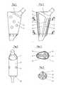
- Fig. 1 den Ausschnitt einer Seitenansicht auf einen erfindungsgemässen Prothesenschaft;
- Fig. 2 eine Ansicht des um 90° gedrehten Prothesenschaftes gemäss Fig. 1;
- Fig. 3 einen teilweise geschnittenen Prothesenschaft gemäss Fig. 1;
- Fig. 4, 5 Horizontalschnitte durch einen Prothesenschaft gemäss Fig. 3.
- 1 shows the detail of a side view of a prosthesis socket according to the invention;
- Fig. 2 is a view of the prosthesis shaft rotated by 90 ° according to Fig. 1;
- FIG. 3 shows a partially sectioned prosthesis socket according to FIG. 1;
- 4, 5 horizontal sections through a prosthesis socket according to FIG. 3.
Die Figuren zeigen eine Femurkopfprothese, die aus einem tragenden Schaftkörper 1 besteht, der proximal Oberflächenbereiche besitzt, die eine poröse, das Einwachsen von Knochengewebe fördernde Struktur 2 aufweisen. Mit dem Schaftkörper 1 ist ein Drahtgeflecht 3 verbunden, welches von distal nach proximal durch Rippen 4 von innen abgestützt ist und welches Hohlräume 6 am Schaftkörper 1 überspannt. Die Hohlräume 6 sind von aussen über distale Oeffnungen 8 zwischen Drahtgeflecht 3 und Schaftkörper 1 und über Aussparungen 7 im Drahtgeflecht 3 zugänglich, um Knochengewebe in die Hohlräume 6 einwachsen zu lassen und über einen Adernbaum zu versorgen.The figures show a femoral head prosthesis which consists of a supporting
Der Schaftkörper 1 bildet im proximalen Bereich mit den Rippen 4, die teilweise in Wülste auslaufen, einen Trägerkörper mit Hohlräumen 6, über die das Drahtgeflecht 3 gespannt ist. Proximal schliesst das Drahtgeflecht 3 mit einer Querrippe 5 ab, während gegen distal Oeffnungen 8 bestehen, durch die ein Adernbaum einwachsen kann. Aussparungen 7 im Drahtgeflecht 3 sollen ebenfalls mit besserer Blutversorgung das Einwachsen des Knochengewebes fördern, ohne zuviel an Stützfläche zu verlieren.The
Die Primärverankerung vom Schaft erfolgt im Schaftunterteil und proximal im Bereich der vorstehenden Rippen 4, 5. Durch das beidseitig vom Drahtgeflecht 3 einwachsende Knochengewebe und durch das teilweise Durchwachsen des Drahtgeflechts entsteht eine intensive Verankerung. Mit seiner begrenzten Nachgiebigkeit im Bereich der überspannten Hohlräume 6 reduziert das Drahtgeflecht Spannungen, die sonst als Spitzen am verankerten Knochengewebe auftreten würden. Das Einwachsen des Knochengewebes in die von Drahtgeflecht überspannten Hohlräume 6 wird durch Beschichten der Wandungen des Schaftkörpers 1 im Bereich der Rippen 4 mit Hydroxylapatit zusätzlich gefördert.The primary anchoring of the shaft takes place in the lower part of the shaft and proximally in the area of the
Claims (3)
Translated fromGermanApplications Claiming Priority (2)
| Application Number | Priority Date | Filing Date | Title |
|---|---|---|---|
| CH2312/90 | 1990-07-11 | ||
| CH231290 | 1990-07-11 |
Publications (1)
| Publication Number | Publication Date |
|---|---|
| EP0466638A1true EP0466638A1 (en) | 1992-01-15 |
Family
ID=4230862
Family Applications (1)
| Application Number | Title | Priority Date | Filing Date |
|---|---|---|---|
| EP91810444AWithdrawnEP0466638A1 (en) | 1990-07-11 | 1991-06-12 | Femoral head prosthesis |
Country Status (1)
| Country | Link |
|---|---|
| EP (1) | EP0466638A1 (en) |
Cited By (4)
| Publication number | Priority date | Publication date | Assignee | Title |
|---|---|---|---|---|
| US5549705A (en)* | 1993-10-26 | 1996-08-27 | Howmedica, Inc. | Prosthesis with integral proximal spacer |
| WO1999037254A1 (en)* | 1998-01-22 | 1999-07-29 | Sulzer Orthopedics, Ltd. | Humeral head prosthesis |
| EP1438932A1 (en)* | 2003-01-17 | 2004-07-21 | WALDEMAR LINK GmbH & Co. KG | Hip prosthesis with stem for implantation into the femur |
| US8187336B2 (en) | 2003-06-16 | 2012-05-29 | Jamali Amir A | Device and method for reconstruction of osseous skeletal defects |
Citations (7)
| Publication number | Priority date | Publication date | Assignee | Title |
|---|---|---|---|---|
| FR2315902A1 (en)* | 1975-07-01 | 1977-01-28 | Ceraver | Metal rod as prosthetic insert into a bone shank - has longitudinal depressions filled with material promoting growth of bone cells |
| DE2758541A1 (en)* | 1976-09-15 | 1979-07-19 | Minnesota Mining & Mfg | PROSTHESIS / BONE CONNECTION SYSTEM |
| EP0071242A2 (en)* | 1981-07-30 | 1983-02-09 | CERAVER Société anonyme dite: | Prosthetic stem composed of titanium or its alloys for the cementless fixation in a long bone |
| FR2519248A1 (en)* | 1981-12-31 | 1983-07-08 | Timoteo Michel | Ball and socket artificial hip joint - uses rugous case in medular cavity to house tail in one piece with pivot locating ball |
| EP0230006A1 (en)* | 1986-01-16 | 1987-07-29 | Waldemar Link (GmbH & Co.) | Bone implant |
| EP0093378B1 (en)* | 1982-05-03 | 1987-08-12 | Waldemar Link (GmbH & Co.) | Femur hip joint prosthesis |
| EP0340174A2 (en)* | 1988-04-29 | 1989-11-02 | G. CREMASCOLI S.p.A. | Composite-material prosthesis femoral stem |
- 1991
- 1991-06-12EPEP91810444Apatent/EP0466638A1/ennot_activeWithdrawn
Patent Citations (7)
| Publication number | Priority date | Publication date | Assignee | Title |
|---|---|---|---|---|
| FR2315902A1 (en)* | 1975-07-01 | 1977-01-28 | Ceraver | Metal rod as prosthetic insert into a bone shank - has longitudinal depressions filled with material promoting growth of bone cells |
| DE2758541A1 (en)* | 1976-09-15 | 1979-07-19 | Minnesota Mining & Mfg | PROSTHESIS / BONE CONNECTION SYSTEM |
| EP0071242A2 (en)* | 1981-07-30 | 1983-02-09 | CERAVER Société anonyme dite: | Prosthetic stem composed of titanium or its alloys for the cementless fixation in a long bone |
| FR2519248A1 (en)* | 1981-12-31 | 1983-07-08 | Timoteo Michel | Ball and socket artificial hip joint - uses rugous case in medular cavity to house tail in one piece with pivot locating ball |
| EP0093378B1 (en)* | 1982-05-03 | 1987-08-12 | Waldemar Link (GmbH & Co.) | Femur hip joint prosthesis |
| EP0230006A1 (en)* | 1986-01-16 | 1987-07-29 | Waldemar Link (GmbH & Co.) | Bone implant |
| EP0340174A2 (en)* | 1988-04-29 | 1989-11-02 | G. CREMASCOLI S.p.A. | Composite-material prosthesis femoral stem |
Cited By (8)
| Publication number | Priority date | Publication date | Assignee | Title |
|---|---|---|---|---|
| US5549705A (en)* | 1993-10-26 | 1996-08-27 | Howmedica, Inc. | Prosthesis with integral proximal spacer |
| WO1999037254A1 (en)* | 1998-01-22 | 1999-07-29 | Sulzer Orthopedics, Ltd. | Humeral head prosthesis |
| US6406496B1 (en) | 1998-01-22 | 2002-06-18 | Sulzer Orthopedics Ltd. | Humerus head prosthesis |
| EP1438932A1 (en)* | 2003-01-17 | 2004-07-21 | WALDEMAR LINK GmbH & Co. KG | Hip prosthesis with stem for implantation into the femur |
| WO2004064689A1 (en)* | 2003-01-17 | 2004-08-05 | Waldemar Link Gmbh & Co. Kg | Hip prosthesis comprising a shaft to be inserted into the femur |
| AU2004206728B2 (en)* | 2003-01-17 | 2009-03-26 | Waldemar Link Gmbh & Co. Kg | Hip prosthesis comprising a shaft to be inserted into the femur |
| US7914585B2 (en) | 2003-01-17 | 2011-03-29 | Waldemar Link Gmbh & Co. Kg | Hip prosthesis including a shaft to be inserted into the femur |
| US8187336B2 (en) | 2003-06-16 | 2012-05-29 | Jamali Amir A | Device and method for reconstruction of osseous skeletal defects |
Similar Documents
| Publication | Publication Date | Title |
|---|---|---|
| DE2611985C3 (en) | Femoral head endoprosthesis | |
| EP0489684B1 (en) | Implant for the construction of bone tissue | |
| DE60009446T2 (en) | BENDING IMPLANT WITH PARTIAL DEMINERALIZED BONE | |
| DE3106917C2 (en) | Process for the production of an implant as a bone substitute | |
| EP1260200B1 (en) | Cementless hip joint endoprosthesis for replacing the surface of the proximal femur | |
| EP0421008B1 (en) | Femoral hip joint endoprosthesis | |
| DE69737504T2 (en) | CERAMIC IMPLANTS AND COMPOSITIONS WITH OSTEOINDUCTIVE ACTIVE SUBSTANCES | |
| DE69728424T2 (en) | SPACER FOR SPIN | |
| DE8237288U1 (en) | Femoral hip joint prosthesis | |
| CH666178A5 (en) | FEMUR HEAD PROSTHESIS. | |
| EP0183744A1 (en) | Artificial joint system and process for its implantation | |
| EP0640326A1 (en) | Element for temporarily increasing the rigidity of a prosthesis | |
| DE2440291A1 (en) | ENDO HIP PROSTHESIS | |
| EP0169976B1 (en) | Shaft for a hip joint prosthesis conically extending from the distal part | |
| EP0332571A1 (en) | Stem for a femural-head prosthesis | |
| EP0366604A1 (en) | Stem for a femoral head prosthesis | |
| EP0243585B1 (en) | Prosthesis stem for implantation into a bone cavity and prosthesis with this stem | |
| EP0466638A1 (en) | Femoral head prosthesis | |
| DE4315143C1 (en) | Thigh part of a hip joint endoprosthesis | |
| CH626249A5 (en) | Joint prosthesis | |
| DE3613657A1 (en) | Endoprosthesis | |
| CH680110A5 (en) | ||
| CH678146A5 (en) | ||
| DE3923154C2 (en) | ||
| DE10212982A1 (en) | Process for implanting an endoprosthesis in a hip joint comprises resecting the joint ball so that when viewed ventrally on the hip joint the resection surface is angled medially from the horizontal by a specified amount |
Legal Events
| Date | Code | Title | Description |
|---|---|---|---|
| PUAI | Public reference made under article 153(3) epc to a published international application that has entered the european phase | Free format text:ORIGINAL CODE: 0009012 | |
| AK | Designated contracting states | Kind code of ref document:A1 Designated state(s):AT CH DE FR GB IT LI | |
| 17P | Request for examination filed | Effective date:19920207 | |
| RAP1 | Party data changed (applicant data changed or rights of an application transferred) | Owner name:GEBRUEDER SULZER AKTIENGESELLSCHAFT Owner name:PROTEK AG | |
| 17Q | First examination report despatched | Effective date:19930611 | |
| 18D | Application deemed to be withdrawn | Effective date:19931022 |