EP0457017A1 - Fixations system for clamps - Google Patents
Fixations system for clampsDownload PDFInfo
- Publication number
- EP0457017A1 EP0457017A1EP91105485AEP91105485AEP0457017A1EP 0457017 A1EP0457017 A1EP 0457017A1EP 91105485 AEP91105485 AEP 91105485AEP 91105485 AEP91105485 AEP 91105485AEP 0457017 A1EP0457017 A1EP 0457017A1
- Authority
- EP
- European Patent Office
- Prior art keywords
- bone
- grasping forceps
- joint
- bone grasping
- forceps according
- Prior art date
- Legal status (The legal status is an assumption and is not a legal conclusion. Google has not performed a legal analysis and makes no representation as to the accuracy of the status listed.)
- Granted
Links
- 210000000988bone and boneAnatomy0.000claimsabstractdescription66
- 230000001097osteosynthetic effectEffects0.000claimsabstractdescription5
- 239000012634fragmentSubstances0.000abstractdescription5
- 208000010392Bone FracturesDiseases0.000description17
- 206010017076FractureDiseases0.000description16
- 208000015181infectious diseaseDiseases0.000description6
- 238000000034methodMethods0.000description5
- 238000010276constructionMethods0.000description4
- 210000004872soft tissueAnatomy0.000description4
- 230000017531blood circulationEffects0.000description3
- 230000035876healingEffects0.000description2
- 0C*(CC(C1)[C@]2C1C*1)C2C1(C)OChemical compoundC*(CC(C1)[C@]2C1C*1)C2C1(C)O0.000description1
- 206010061599Lower limb fractureDiseases0.000description1
- 208000027418Wounds and injuryDiseases0.000description1
- 244000052616bacterial pathogenSpecies0.000description1
- 230000000903blocking effectEffects0.000description1
- 230000036770blood supplyEffects0.000description1
- 210000004204blood vesselAnatomy0.000description1
- 239000003795chemical substances by applicationSubstances0.000description1
- 230000006378damageEffects0.000description1
- 238000001514detection methodMethods0.000description1
- 230000000694effectsEffects0.000description1
- 208000014674injuryDiseases0.000description1
- 238000003780insertionMethods0.000description1
- 230000037431insertionEffects0.000description1
- 238000005259measurementMethods0.000description1
- 230000017074necrotic cell deathEffects0.000description1
- 210000005036nerveAnatomy0.000description1
- 230000000451tissue damageEffects0.000description1
- 231100000827tissue damageToxicity0.000description1
Images

Classifications
- A—HUMAN NECESSITIES
- A61—MEDICAL OR VETERINARY SCIENCE; HYGIENE
- A61B—DIAGNOSIS; SURGERY; IDENTIFICATION
- A61B17/00—Surgical instruments, devices or methods
- A61B17/28—Surgical forceps
- A61B17/2812—Surgical forceps with a single pivotal connection
- A—HUMAN NECESSITIES
- A61—MEDICAL OR VETERINARY SCIENCE; HYGIENE
- A61B—DIAGNOSIS; SURGERY; IDENTIFICATION
- A61B17/00—Surgical instruments, devices or methods
- A61B17/56—Surgical instruments or methods for treatment of bones or joints; Devices specially adapted therefor
- A61B17/58—Surgical instruments or methods for treatment of bones or joints; Devices specially adapted therefor for osteosynthesis, e.g. bone plates, screws or setting implements
- A61B17/88—Osteosynthesis instruments; Methods or means for implanting or extracting internal or external fixation devices
- A61B17/8866—Osteosynthesis instruments; Methods or means for implanting or extracting internal or external fixation devices for gripping or pushing bones, e.g. approximators
- A—HUMAN NECESSITIES
- A61—MEDICAL OR VETERINARY SCIENCE; HYGIENE
- A61B—DIAGNOSIS; SURGERY; IDENTIFICATION
- A61B17/00—Surgical instruments, devices or methods
- A61B17/56—Surgical instruments or methods for treatment of bones or joints; Devices specially adapted therefor
- A61B17/58—Surgical instruments or methods for treatment of bones or joints; Devices specially adapted therefor for osteosynthesis, e.g. bone plates, screws or setting implements
- A61B17/60—Surgical instruments or methods for treatment of bones or joints; Devices specially adapted therefor for osteosynthesis, e.g. bone plates, screws or setting implements for external osteosynthesis, e.g. distractors, contractors
- A61B17/64—Devices extending alongside the bones to be positioned
- A61B17/6458—Devices extending alongside the bones to be positioned with pin-clamps fixed at ends of connecting element
Definitions
- the inventionrelates to a bone grasping forceps according to the preamble of claim 1 and to an osteosynthetic fixation device according to the preamble of claim 9.
- the inventionseeks to remedy this.
- the inventionhas for its object to provide a simple, manually operated bone grasping forceps, which allows a non-invasive, temporary fixation of bone fractures.
- the inventionsolves the problem with a bone forceps, which has the features of claim 1, and an osteosynthetic fixation device, which has the features of claim 9.
- the boneis held between the pointed lips of the bone grasping forceps according to the invention.
- Thishas the advantage that the bone does not have to be drilled through and therefore no heat necrosis is caused by the drill and that the blood flow to the bone is minimally disturbed.
- Several such forceps-like bone grasping forcepscan be connected to each other externally like screws or nails.
- the main indication of the bone grasping forceps according to the inventionis the temporary fixation of open lower leg fractures. This means that they can only be used for intraoperative reduction of the fracture, or after reduction has been left on the bone until soft tissue healing is complete. In both cases, can be with Bone grasping forceps can be changed (e.g. intramedullary nailing).
- the use of the bone grasping forceps according to the inventionis not limited to the classic "external fixator method", but is used wherever a fracture has to be reduced or the bone length and rotation have to be maintained.
- a useful application of the bone grasping forceps according to the inventionis also the temporary locking of an intramedullary nail, since the attachment of the bone grasping forceps according to the invention can be carried out much easier, faster and without the use of X-rays compared to screws. The same applies to indirect reduction with the distractor.
- the bone grasping forceps according to the inventioncan be used in order to avoid the bores in the bone which are unnecessary for the fracture treatment.
- the bone grasping forceps according to the inventionoffer enormous advantages in the treatment of war injuries or in disasters where the fracture treatment is carried out quickly and in part by minimally trained persons without generous aids must become. Given these circumstances, the bone grasping forceps according to the invention offer a much lower risk of infection and no additional instruments, machines, etc. are required. Fractures that are not adequately treated can easily be corrected or re-fixed at a later point in time.
- the local application of the bone grasping forceps according to the inventiondepends on the soft tissue structures (blood vessels, nerves, etc.) that surround the bone. If there are endangered structures, access to the bone, like when using the external fixator, must be carefully prepared.
- the bone grasping forceps according to the inventioncan be handled by the surgeon like other forceps-like instruments. The surgeon is thus already experienced in handling such devices and knows how to measure the clamping force of the bone forceps.
- the correct positioning of a pair of pliersis also much easier than, for example, the correct positioning of a clamp.
- the pliers lipsare preferably designed so that they have a resilient property. This has the advantage that if the tips of the forceps sink into the bone or slip slightly, there is no noticeable loss of force of the forceps on the bone.
- the pliers lockis located in the pliers lock and can be deactivated by simply tightening a nut. This has the advantage that the handles can be removed after the bone grasping forceps have been successfully fixed to the bone in order to make the external construction as small as possible.
- the connecting pinwhich can move freely in one direction, enables the connection of several, individually placed bone grasping devices to form a straight connecting tube.
- the bone grasping forceps shown in FIGS. 1 and 2each consist essentially of a swivel joint 1, two lips 2, 3 and two legs 4, 5.
- the swivel joint 1can be actuated by manual actuation of the legs 4, 5, whereby the lips 2, 3 move against one another.
- the two jaw-shaped lips 2,3are by a cross-sectional constriction 15, respectively. 16 resiliently designed so that the surgeon can exert a manually metered resilient force when grasping a bone fragment.
- the free ends of the two lips 2, 3are pointed to ensure reliable detection of the bone fragments.
- the swivel joint 1can be unblocked again by simply unscrewing the locking nut 7.
- the two legs 4, 5 designed as handlescan be removed from the joint 1.
- the legs 4, 5 - as shown in FIG. 3 -are preferably provided at their articulated end with a square 17 which fits into corresponding, radially arranged openings 18 (in the articulated bore element 20) and 19 (in the joint axis element 10) and can be removed therefrom. This measure allows the osteosynthetically active part of the bone forceps (fixation clamp) to be kept as small as possible.
- the bone grasping forcepshas a connecting pin 9 which can be rotated about the axis 6 of the joint axis element 10 and can be locked in any position by means of a locking nut 8.
- This connecting pin 9can either be attached preoperatively or only intraoperatively if the spatial conditions so suggest.
- This connecting pin 9it is possible to connect a whole series of bone grasping pliers to one another in order to produce a larger bond.
- the pins 9can be connected to one another in a conventional manner with the usual aids (rods, clamps and the like), as are used for external fixators.
- the swivel joint 1in a preferred embodiment consists of an axis joint with a joint axis element 10 and a joint bore element 20 corresponding to the joint axis element 10.
- the two elements 10, 20have plate-shaped base bodies 21, 22, each of which is one of the wear both lips 2,3.
- the base body 21 of the articulated axis element 10carries an axially arranged cylindrical articulated axis 6, which is provided with a thread 23, 24 at each of its two ends.
- the base body 22 of the joint axis element 20has a central bore 24 which is intended to receive the cylindrical joint axis 6.
- the two plate-shaped base bodies 21, 22are each provided with two movement limiters (11, 12; 13, 14) arranged concentrically offset from one another, which limit the mutual rotation of the two elements 10, 20 in the positive and negative directions of rotation.
- an intermediate disk 27 to be located between the latter and the articulation bore element 20is provided, which is in the center has a hexagonal opening 28 and on its underside a concentrically arranged grooved circular zone 29.
- the base body 22 of the articulated axis element 20has on its upper side a grooved circular zone 25 which corresponds to the circular zone 29 of the intermediate disk 27.
- That part of the joint axis 6 which comes to lie at the level of the intermediate disc 27is formed with a hexagonal cross section 30 in order to allow the intermediate disc 27 to rotate when the joint axis 6 rotates.
- This constructionallows the two elements 10 and 20 to be moved against one another when the locking screw 7 is unscrewed (the two grooved circular rings 25, 29 are not in engagement with one another), while the two circular rings 25 and 29 are clamped against one another with their structures when the locking screw 7 is screwed on, So that the The intermediate disc 27 and thus also the section 30 of the joint axis 6 which is stuck in the hexagonal opening 27 is blocked with respect to the joint bore part 20.
- the connecting pin 9is provided with a plate-shaped base body 30, which has an annular, grooved zone 31 on its upper side, which corresponds to a grooved circular zone 32 located on the underside of the plate-shaped base body 21 of the articulated axis element 10.
- the plate-shaped base body 30has a centrally arranged bore 33 which can accommodate the hinge axis 6.
- the hexagon nut 8which has a central bore 34 with an internal thread 35, the connecting pin 9 can be connected to the joint axis 6 (the internal thread 35 of the bore 34 corresponds to the external thread 24 of the joint axis 6).
- the connecting pin 9can be rotated as desired about the axis 6 of the articulated axis element 10; by tightening the nut 8, the two grooved circular zones 31 and 32 interlock, so that the connecting pin 9 can be blocked in any position.
- the connecting pin 9there is the possibility of attaching two or more bone grasping forceps to the rods of an external fixator by means of auxiliary elements that are common in osteosynthesis (clamps, clamps, etc.), in order to obtain an extremely stable structure in this way.
Landscapes
- Health & Medical Sciences (AREA)
- Surgery (AREA)
- Life Sciences & Earth Sciences (AREA)
- Medical Informatics (AREA)
- Animal Behavior & Ethology (AREA)
- Engineering & Computer Science (AREA)
- Biomedical Technology (AREA)
- Heart & Thoracic Surgery (AREA)
- Orthopedic Medicine & Surgery (AREA)
- Molecular Biology (AREA)
- Nuclear Medicine, Radiotherapy & Molecular Imaging (AREA)
- General Health & Medical Sciences (AREA)
- Public Health (AREA)
- Veterinary Medicine (AREA)
- Ophthalmology & Optometry (AREA)
- Surgical Instruments (AREA)
- Orthopedics, Nursing, And Contraception (AREA)
Abstract
Description
Translated fromGermanDie Erfindung bezieht sich auf eine Knochenfasszange gemäss dem Oberbegriff des Anspruchs 1 sowie auf eine osteosynthetische Fixationsvorrichtung gemäss dem Oberbegriff des Anspruchs 9.The invention relates to a bone grasping forceps according to the preamble of
Zur Behandlung von Knochenbrüchen, insbesondere zur Fixierung von Knochen oder Knochenfragmente, stehen dem Chirurgen eine Vielzahl von Osteosynthesemitteln zur Verfügung.
In den letzten Jahren konnte man eindeutig die Tendenz von der konservativen zur operativen Frakturversorgung beobachten. Dabei stand zu Beginn der operativen Frakturbehandlung die optimale Rekonstruktion der Fraktur im Vordergrund. Der Blutversorgung und den Weichteilen rund um die Fraktur wurde keine grosse Beachtung geschenkt. Das Ziel der absoluten Stabilität wurde ohne Rücksicht auf die Biologie angestrebt. Mit der Verbreitung der geschlossenen Marknagelung wurde erkannt, dass eine absolute Stabilität der Fraktur nicht unbedingt erforderlich ist. Trotz zum Teil grosser Instabilität der Fraktur, vermochte die nur minimal gestörte Biologie die Fraktur zu heilen. Diese neu erlangte Kenntnis, wurde auch bei anderen Osteosynthesearten berücksichtigt. Bei der Plattenosteosynthese z.B. werden weniger Schrauben, kleinere und kürzere Platten verwendet. Das gleiche gilt auch beim Fixateur externe. An Stelle von riesigen, mehrdimensionalen Konstruktionen, wenn möglich noch mit interfragmentärer Zugschraube, setzte sich der einfache unilaterale Fixateur durch.
Trotz der "biologischen" Anwendung des Fixateur externe gelingt eine Ausheilung der Fraktur nicht immer. Das heisst, oft muss die Fraktur mit einem zweiten Eingriff und einer anderen Osteosynthesemethode behandelt werden. Der Hauptgrund für die Komplikationen sind die Nägel oder Schrauben, die von aussen durch die Haut und die Weichteile in den Knochen eingebracht werden. Entlang dieser Nägel oder Schrauben gelangen Keime bis in den Knochen, was zu einer sogenannten "Pintrak-Infektion" führt. Ist eine derartige Infektion vorhanden, müssen die Nägel oder Schrauben entfernt werden. Während einer Heilungszeit der Infektion von ca. 10 Tagen kann die Fraktur nicht operativ fixiert werden. Das hat zur Folge, dass der Patient während dieser Zeit immobilisiert werden muss.
Neben diesem Nachteil des herkömmlichen Fixateur externe, zeichnet sich ein weiterer Nachteil immer deutlicher ab. Messungen mit Laserdopplern, mit denen die Durchblutung des Knochens klinisch gemessen werden kann, haben gezeigt, dass das Einbringen von Nägeln oder Schrauben die Durchblutung des Knochens erheblich stören. Für den Kliniker bedeutet das, dass er schon beim Einbringen von Fixateur externe, Nägeln oder Schrauben den weiteren Behandlungsablauf vorgibt (Gefahr von Pintrak-Infektion, 10-tägige Immobilisation des Patienten bei Verfahrenswechsel). Negativ wirkt sich diese Tatsache dann aus, wenn der Fixateur externe aus zeitlichen Gründen, oder zur momentanen Behandlung von Weichteilschäden benutzt wird. Stellt man sich die Situation einer Katastrophe vor (Flugzeugabsturz, Zugsunglück usw.), so müssen die Verletzten schnellstmöglich behandelt werden. Für solche Fälle bietet sich der Fixateur externe vorzüglich an. Die vorher beschriebenen Probleme werden jedoch auch hier nicht ausbleiben.A large number of osteosynthesis agents are available to the surgeon for the treatment of bone fractures, in particular for the fixation of bones or bone fragments.
In recent years, there has been a clear trend from conservative to surgical fracture care. At the beginning of surgical fracture treatment, the focus was on optimal reconstruction of the fracture. The blood supply and the soft parts around the fracture were not given much attention. The goal of absolute stability was aimed at regardless of biology. With the spread of closed intramedullary nailing, it was recognized that absolute stability of the fracture is not absolutely necessary. Despite the great instability of the fracture, the minimally disturbed biology was able to heal the fracture. This newly acquired knowledge was also taken into account in other types of osteosynthesis. In plate osteosynthesis, for example, fewer screws, smaller and shorter plates are used. The same applies to external fixators. Instead of huge, Multi-dimensional constructions, if possible with an interfragmentary lag screw, prevailed in the simple unilateral fixator.
Despite the "biological" use of the external fixator, the fracture does not always heal. This means that the fracture often has to be treated with a second procedure and a different osteosynthesis method. The main reason for the complications are the nails or screws that are inserted from the outside through the skin and soft tissues into the bones. Germs reach the bones along these nails or screws, which leads to a so-called "Pintrak infection". If there is such an infection, the nails or screws must be removed. The fracture cannot be surgically fixed during a healing period of the infection of approx. 10 days. As a result, the patient has to be immobilized during this time.
In addition to this disadvantage of the conventional external fixator, another disadvantage is becoming increasingly clear. Measurements with laser Doppler, with which the blood circulation in the bone can be measured clinically, have shown that the insertion of nails or screws significantly disturb the blood circulation in the bone. For the clinician, this means that he already specifies the further course of treatment when inserting external fixators, nails or screws (risk of Pintrak infection, 10-day immobilization of the patient when changing procedures). This fact has a negative effect if the external fixator is used for time reasons or for the current treatment of soft tissue damage. Imagine the situation of a disaster (plane crash, Train accident, etc.), the injured must be treated as soon as possible. The external fixator is ideal for such cases. However, the problems described above will not fail to materialize here.
Hier will die Erfindung Abhilfe schaffen. Der Erfindung liegt die Aufgabe zugrunde, eine einfache, manuell bedienbare Knochenfasszange zu schaffen, welche eine nicht-invasive, temporäre Fixation von Knochenfrakturen gestattet.The invention seeks to remedy this. The invention has for its object to provide a simple, manually operated bone grasping forceps, which allows a non-invasive, temporary fixation of bone fractures.
Die Erfindung löst die gestellte Aufgabe mit einer Knochenfasszange, welche die Merkmale des Anspruchs 1 aufweist, sowie einer osteosynthetischen Fixationsvorrichtung, welche die Merkmale des Anspruchs 9 aufweist.The invention solves the problem with a bone forceps, which has the features of
An Stelle einer Schraube oder eines Nagels, wird der Knochen zwischen den spitz ausgestalteten Lippen der erfindungsgemässen Knochenfasszange gehalten. Das hat den Vorteil, dass der Knochen nicht durchbohrt werden muss und dadurch keine Hitzenekrose durch den Bohrer hervorgerufen wird und dass die Durchblutung des Knochens in minimalster Weise gestört wird. Mehrere solcher zangenartiger Knochenfasszangen können gleich wie Schrauben oder Nägel extern miteinander verbunden werden. Die Hauptindikation der erfindungsgemässen Knochenfasszange ist die temporäre Fixation von offenen Unterschenkelfrakturen. Das heisst, sie können lediglich zur intraoperativen Reposition der Fraktur verwendet werden, oder nach erfolgter Reposition solange am Knochen belassen werden, bis die Weichteilheilung abgeschlossen ist. In beiden Fällen kann bei liegenden Knochenfasszangen ein Verfahrenswechsel durchgeführt werden (z.B. Marknagelung). Die Belassung der Knochenfasszangen bis zur Ausheilung der Fraktur ist problemlos möglich, aber wegen der einfachen Möglichkeit eines Verfahrenswechsels selten sinnvoll.
Sollte es während der Behandlungszeit zu einer "Pintrak-Infektion" kommen, ist diese nur oberflächlich und kann einfach behandelt werden, da der Knochen unterhalb der Spitzen der Knochenfasszange vital ist.Instead of a screw or a nail, the bone is held between the pointed lips of the bone grasping forceps according to the invention. This has the advantage that the bone does not have to be drilled through and therefore no heat necrosis is caused by the drill and that the blood flow to the bone is minimally disturbed. Several such forceps-like bone grasping forceps can be connected to each other externally like screws or nails. The main indication of the bone grasping forceps according to the invention is the temporary fixation of open lower leg fractures. This means that they can only be used for intraoperative reduction of the fracture, or after reduction has been left on the bone until soft tissue healing is complete. In both cases, can be with Bone grasping forceps can be changed (e.g. intramedullary nailing). It is possible to leave the bone grasping forceps until the fracture has healed, but it rarely makes sense because of the simple possibility of changing the procedure.
If a "Pintrak infection" occurs during the treatment period, it is only superficial and can be treated easily since the bone beneath the tips of the bone grasping forceps is vital.
Die Anwendung der erfindungsgemässen Knochenfasszange beschränkt sich nicht nur auf die klassische "Fixateur externe Methode", sondern kommt überall dort zum Einsatz, wo eine Fraktur reponiert oder die Knochenlänge und Rotation gehalten werden muss.
Eine nutzbringende Anwendung der erfindungsgemässen Knochenfasszange besteht überdies in der temporären Verriegelung eines Marknagels, da das Anbringen der erfindungsgemässen Knochenfasszange im Vergleich zu Schrauben viel einfacher, schneller und ohne Verwendung von Röntgenstrahlen durchgeführt werden kann.
Das gleiche gilt bei der indirekten Reposition mit dem Distraktor. Anstelle von Schanzschen Schrauben können die erfindungsgemässen Knochenfasszangen verwendet werden, um die für die Frakturversorgung unnötigen Bohrungen im Knochen zu vermeiden.The use of the bone grasping forceps according to the invention is not limited to the classic "external fixator method", but is used wherever a fracture has to be reduced or the bone length and rotation have to be maintained.
A useful application of the bone grasping forceps according to the invention is also the temporary locking of an intramedullary nail, since the attachment of the bone grasping forceps according to the invention can be carried out much easier, faster and without the use of X-rays compared to screws.
The same applies to indirect reduction with the distractor. Instead of Schanz screws, the bone grasping forceps according to the invention can be used in order to avoid the bores in the bone which are unnecessary for the fracture treatment.
Enorme Vorteile bietet die erfindungsgemässe Knochenfasszange bei der Behandlung von Kriegsverletzten oder in Katastrophenfällen, wo die Frakturversorgung ohne grosszügige Hilfsmittel, schnell und zum Teil von minimal geschulten Personen durchgeführt werden muss. Bei diesen Gegebenheiten bietet die erfindungsgemässe Knochenfasszange ein viel geringeres Infektionsrisiko und es werden keine zusätzlichen Instrumente, Maschinen usw. benötigt. Ungenügend gut versorgte Frakturen können, in einem späteren Zeitpunkt, problemlos korrigiert oder neu fixiert werden.The bone grasping forceps according to the invention offer enormous advantages in the treatment of war injuries or in disasters where the fracture treatment is carried out quickly and in part by minimally trained persons without generous aids must become. Given these circumstances, the bone grasping forceps according to the invention offer a much lower risk of infection and no additional instruments, machines, etc. are required. Fractures that are not adequately treated can easily be corrected or re-fixed at a later point in time.
Die örtliche Anwendung der erfindungsgemässen Knochenfasszangen hängt von den Weichteilstrukturen ab (Blutgefässe, Nerven usw.), die den Knochen umschliessen. Sind gefährdete Strukturen vorhanden, muss der Zugang zum Knochen, wie bei der Anwendung des Fixateurs externe, vorsichtig präpariert werden.The local application of the bone grasping forceps according to the invention depends on the soft tissue structures (blood vessels, nerves, etc.) that surround the bone. If there are endangered structures, access to the bone, like when using the external fixator, must be carefully prepared.
Die Ausbildung der Erfindung in Form einer Zange hat vielerlei Vorteile.The design of the invention in the form of pliers has many advantages.
Die erfindungsgemässe Knochenfasszange kann wie andere zangenartige Instrumente vom Chirurgen gehandhabt werden. Der Chirurg ist somit bereits im Umgang mit solchen Geräten geübt, und weiss wie die Klemmkraft der Knochenfasszange dosiert werden kann. Auch ist das positionsrichtige Ansetzen einer Zange viel einfacher als z.B. das richtige Ansetzen einer Spannzwinge. Die Zangenlippen sind vorzugsweise so konstruiert, dass sie eine federnde Eigenschaft haben. Das hat den Vorteil, dass bei eventuellem Einsinken oder leichtem Abrutschen der Zangenspitzen am Knochen, kein merklicher Kraftverlust der Zange auf den Knochen auftritt.The bone grasping forceps according to the invention can be handled by the surgeon like other forceps-like instruments. The surgeon is thus already experienced in handling such devices and knows how to measure the clamping force of the bone forceps. The correct positioning of a pair of pliers is also much easier than, for example, the correct positioning of a clamp. The pliers lips are preferably designed so that they have a resilient property. This has the advantage that if the tips of the forceps sink into the bone or slip slightly, there is no noticeable loss of force of the forceps on the bone.
Der Zangenverschluss befindet sich im Zangenschloss und kann durch einfaches Festdrehen einer Mutter desaktiviert werden. Das hat den Vorteil, dass die Handgriffe nach erfolgreicher Fixation der Knochenfasszange am Knochen entfernt werden können, um so die externe Konstruktion so klein wie möglich zu gestalten.
Der in einer Richtung frei bewegliche Verbindungsstift, ermöglicht die Verbindung von mehreren, einzeln gesetzten Knochenfassvorrichtungen zu einem geraden Verbindungsrohr.The pliers lock is located in the pliers lock and can be deactivated by simply tightening a nut. This has the advantage that the handles can be removed after the bone grasping forceps have been successfully fixed to the bone in order to make the external construction as small as possible.
The connecting pin, which can move freely in one direction, enables the connection of several, individually placed bone grasping devices to form a straight connecting tube.
Ein Ausführungsbeispiel der Erfindung, welches zugleich das Funktionsprinzip erläutert, ist in der Zeichnung dargestellt und wird im folgenden näher beschrieben.
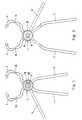
- Fig. 1 stellt eine Aufsicht auf die erfindungsgemässe Knochenfasszange dar;
- Fig. 2 stellt eine Ansicht von unten der Knochenfasszange mit einem Verbindungsstift dar;
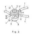
- Fig. 3 stellt eine perspektivische Darstellung der Knochenfasszange nach Fig. 1 dar; und
- Fig. 4 stellt eine Explosionszeichnung der Knochenfasszange nach Fig. 2 dar.
- 1 shows a top view of the bone grasping forceps according to the invention;
- Fig. 2 illustrates a bottom view of the bone forceps with a connecting pin;
- Fig. 3 is a perspective view of the bone grasping forceps according to Fig. 1; and
- FIG. 4 shows an exploded view of the bone grasping forceps according to FIG. 2.
Die in den Fig. 1 und 2 je von oben und von unten dargestellte Knochenfasszange besteht im wesentlichen aus einem Drehgelenk 1, zwei Lippen 2,3 und zwei Schenkeln 4,5. Das Drehgelenk 1 kann durch manuelle Betätigung der Schenkel 4,5 betätigt werden, wodurch sich die Lippen 2,3 gegeneinander bewegen.
Die beiden kieferförmig gebogenen Lippen 2,3 sind durch eine Querschnittsverengung 15, resp. 16 federnd ausgebildet, so dass der Chirurg beim Fassen eines Knochenfragmentes eine manuell dosierte federnde Kraft ausüben kann. Die freien Enden der beiden Lippen 2,3 sind spitz ausgebildet um eine sichere Erfassung der Knochenfragmente zu gewährleisten.The bone grasping forceps shown in FIGS. 1 and 2 each consist essentially of a
The two jaw-shaped
Nach erfolgter Erfassung des, resp. der erwünschten Knochenfragmente kann durch einfaches Zuschrauben der Feststellmutter 7, das Drehgelenk 1, bzw. seine beiden Elemente, nämlich das Gelenkachselement 10 und das Gelenkbohrungselement 20, gegeneinander blockiert werden, wobei die vom Chirurgen aufgebrachte Federspannung bestehen bleibt und eine Lockerung der Zangenspannung verhindert. Durch einfaches Losschrauben der Feststellmutter 7 lässt sich das Drehgelenk 1 wieder deblockieren.After the, or the desired bone fragments can be blocked against each other by simply screwing the locking nut 7, the
Nachdem die Knochenfasszange am gewünschten Ort mit der gewünschten Federspannung fixiert worden ist können die beiden als Handgriffe ausgebildeten Schenkel 4,5 vom Gelenk 1 entfernt werden. Zu diesem Zweck sind die Schenkel 4,5 - wie in Fig. 3 dargestellt - an ihrem gelenkseitigen Ende vorzugsweise mit einem Vierkant 17 versehen, der in korrespondierende, radial angeordnete Öffnungen 18 (im Gelenkbohrungselement 20) und 19 (im Gelenkachselementes 10) eingesteckt und daraus wieder entfernt werden kann. Diese Massnahme gestattet es den osteosynthetisch wirksamen Teil der Knochenfasszange (Fixationsklammer) möglichst klein zu halten.After the bone grasping forceps have been fixed at the desired location with the desired spring tension, the two
Wie in Fig. 2 dargestellt weist die Knochenfasszange einen um die Achse 6 des Gelenkachselementes 10 rotierbar angeordneten, mittels einer Feststellmutter 8 in jeder beliebigen Position blockierbaren Verbindungsstift 9 auf. Dieser Verbindungsstift 9 kann entweder schon präoperativ angebracht werden oder auch erst intraoperativ, falls die räumlichen Verhältnisse dies nahe legen. Mittels dieses Verbindungsstifts 9 ist es möglich eine ganze Serie von Knochenfasszangen untereinander zu verbinden um damit einen grösseren Verbund herzustellen. Die Verbindung der Stifte 9 untereinander kann auf konventionelle Weise erfolgen mit den üblichen Hilfsmitteln (Stäbe, Klemmen u.ä.), wie sie bei Fixateur externes angewendet werden.As shown in FIG. 2, the bone grasping forceps has a connecting
Wie in Fig. 4 dargestellt, besteht das Drehgelenk 1 bei einer bevorzugten Ausführungsform aus einem Achsengelenk mit einem Gelenkachselement 10 und einem mit dem Gelenkachselement 10 korrespondierenden Gelenkbohrungselement 20. Die beiden Elemente 10,20 weisen tellerförmige Grundkörper 21,22 auf, welche je eine der beiden Lippen 2,3 tragen. Der Grundkörper 21 des Gelenkachselementes 10 trägt eine axial angeordnete zylindrischen Gelenkachse 6, welche an ihren beiden Enden mit je einem Gewinde 23,24 versehen ist. Der Grundkörper 22 des Gelenkachselementes 20 weist eine zentrale Bohrung 24 auf, welche dazu bestimmt ist die zylindrischen Gelenkachse 6 aufzunehmen.As shown in FIG. 4, the swivel joint 1 in a preferred embodiment consists of an axis joint with a
Die beiden tellerförmigen Grundkörper 21,22 sind mit je zwei konzentrisch gegeneinander versetzt angeordneten Bewegungsbegrenzern (11,12;13,14) versehen, welche die gegenseitige Rotation der beiden Elemente 10,20 in positiver und negativer Drehrichtung begrenzen.The two plate-shaped
Um die Position des Gelenkachselementes 10 gegenüber dem Gelenkbohrungselement 20 in lösbarer Weise fixierbar zu gestalten (Blockierung des Gelenkes 1) ist, neben der eine Bohrung 26 aufweisenden Feststellschraube 7, eine zwischen letzterer und dem Gelenkbohrungselement 20 zu liegen kommende Zwischenscheibe 27 vorgesehen, welche im Zentrum eine sechskantige Öffnung 28 und an ihrer Unterseite eine konzentrisch angeordnete gerillte Kreiszone 29 aufweist. Der Grundkörper 22 des Gelenkachselementes 20 weist an seiner Oberseite eine mit der Kreiszone 29 der Zwischenscheibe 27 korrespondierende, gerillte Kreiszone 25 auf. Schliesslich ist derjenige Teil der Gelenkachse 6, der auf Höhe der Zwischenscheibe 27 zu liegen kommt mit einem sechskantigen Querschnitt 30 ausgebildet um bei einer Drehung der Gelenkachse 6 die Zwischenscheibe 27 mitrotieren zu lassen.
Diese Konstruktion erlaubt es bei losgeschraubter Feststellschraube 7 die beiden Elemente 10 und 20 gegeneinander zu bewegen (die beiden gerillten Kreisringe 25,29 stehen nicht miteinander im Eingriff), währenddem bei festgeschraubter Feststellschraube 7 die beiden Kreisringe 25 und 29 mit ihren Strukturierungen gegeneinander festgeklemmt sind, so dass die Zwischenscheibe 27 und damit auch der in der sechskantigen Öffnung 27 festsitzende Abschnitt 30 der Gelenkachse 6 gegenüber dem Gelenkbohrungsteil 20 blockiert ist.In order to make the position of the
This construction allows the two
Mittels einer ähnlichen Konstruktion ist es möglich den Verbindungsstift 9 in seiner radialen Position zu fixieren. Zu diesem Zweck ist der Verbindungsstift 9 mit einem tellerförmigen Grundkörper 30 versehen, der an seiner Oberseite eine kreisringförmige, gerillte Zone 31 aufweist, welche mit einer an der Unterseite des tellerförmigen Grundkörpers 21 des Gelenkachselementes 10 befindlichen gerillten Kreiszone 32 korrespondiert.
Der tellerförmigen Grundkörper 30 weist eine zentrisch angeordnete Bohrung 33 auf, welche die Gelenkachse 6 aufnehmen kann. Mittels der Sechskant-Mutter 8, welche eine zentrische Bohrung 34 mit Innengewinde 35 aufweist kann der Verbindungsstift 9 mit der Gelenkachse 6 verbunden werden (das Innengewinde 35 der Bohrung 34 korrespondiert mit dem Aussengewinde 24 der Gelenkachse 6).
Wird die Mutter 8 nur teilweise auf das Gewinde 24 aufgeschraubt, so kann der Verbindungsstift 9 beliebig um die Achse 6 des Gelenkachselementes 10 rotiert werden; durch Festziehen der Mutter 8 verzahnen sich die beiden gerillten Kreiszonen 31 und 32, so dass der Verbindungsstift 9 in jeder beliebigen Position blockiert werden kann.By means of a similar construction it is possible to fix the connecting
The plate-shaped
If the
Dank des Verbindungsstiftes 9 besteht die Möglichkeit zwei oder mehr Knochenfasszangen mittels in der Osteosynthese üblicher Hilfselemente (Klammern, Zwingen u.ä.) an Stäbe eines Fixateurs externe zu befestigen, um auf diese Weise ein äusserst stabiles Gebilde zu erhalten.Thanks to the connecting
Claims (8)
Translated fromGermanApplications Claiming Priority (2)
| Application Number | Priority Date | Filing Date | Title |
|---|---|---|---|
| CH1640/90ACH681422A5 (en) | 1990-05-15 | 1990-05-15 | |
| CH1640/90 | 1990-05-15 |
Publications (2)
| Publication Number | Publication Date |
|---|---|
| EP0457017A1true EP0457017A1 (en) | 1991-11-21 |
| EP0457017B1 EP0457017B1 (en) | 1995-09-20 |
Family
ID=4215193
Family Applications (1)
| Application Number | Title | Priority Date | Filing Date |
|---|---|---|---|
| EP91105485AExpired - LifetimeEP0457017B1 (en) | 1990-05-15 | 1991-04-06 | Fixations system for clamps |
Country Status (6)
| Country | Link |
|---|---|
| EP (1) | EP0457017B1 (en) |
| JP (1) | JP3130560B2 (en) |
| AT (1) | ATE128022T1 (en) |
| CA (1) | CA2042573C (en) |
| CH (1) | CH681422A5 (en) |
| DE (1) | DE59106504D1 (en) |
Cited By (6)
| Publication number | Priority date | Publication date | Assignee | Title |
|---|---|---|---|---|
| DE4226790C1 (en)* | 1992-08-13 | 1993-09-16 | Aesculap Ag, 78532 Tuttlingen, De | Osteo-synthetic stirrup clasp for fixing bone fragments - comprises fixation stirrup, fixation pin and connecting component together with guide socket |
| DE19520464C1 (en)* | 1995-06-03 | 1997-02-27 | Univ Schiller Jena | Spike-type external fixator for broken bones |
| WO1998020802A1 (en) | 1996-11-13 | 1998-05-22 | Synthes Ag Chur | Device for repositioning fractured bone fragments |
| WO2000016709A1 (en) | 1998-09-17 | 2000-03-30 | Synthes Ag Chur | Repositioning instrument for the fixation of bone fractures |
| CN113069197A (en)* | 2021-04-12 | 2021-07-06 | 宋鹏 | Bone block lifting and fixing device and installation method |
| CN114010291A (en)* | 2021-03-31 | 2022-02-08 | 上海黑焰医疗科技有限公司 | External fixation clamp for fracture and system thereof |
Families Citing this family (4)
| Publication number | Priority date | Publication date | Assignee | Title |
|---|---|---|---|---|
| DE29805703U1 (en) | 1998-03-28 | 1998-08-27 | Brehm, Peter, 91085 Weisendorf | Bone grasping forceps |
| US8197506B2 (en)* | 2007-09-14 | 2012-06-12 | Kenneth Burke | Wound closing device |
| CN105943219A (en)* | 2016-05-16 | 2016-09-21 | 河北医科大学第三医院 | Calcaneus bone fracture compression restoration device |
| JP7226840B2 (en)* | 2021-02-20 | 2023-02-21 | 株式会社フジフレックスマーケティング | reduction forceps |
Citations (7)
| Publication number | Priority date | Publication date | Assignee | Title |
|---|---|---|---|---|
| US1635137A (en)* | 1927-01-11 | 1927-07-05 | Clarence E Mullens | Bone clamp |
| FR752676A (en)* | 1932-06-28 | 1933-09-28 | Gentile Et Cie P | Improvements to davits |
| US2427128A (en)* | 1946-01-28 | 1947-09-09 | Zimmer Mfg Company | Surgical bone clamp |
| US2631585A (en)* | 1949-09-06 | 1953-03-17 | Siebrandt Francture Equipment | Bone reducing tool |
| CH492443A (en)* | 1967-06-30 | 1970-06-30 | Sampson Arnold | Extracortical stapler |
| US4475544A (en)* | 1982-02-23 | 1984-10-09 | Reis Norman I | Bone gripping forceps |
| FR2557933A1 (en)* | 1984-01-10 | 1985-07-12 | Srebot | Articulation device for assembling several elements, especially for an external fixture intended for osteosynthesis. |
- 1990
- 1990-05-15CHCH1640/90Apatent/CH681422A5/denot_activeIP Right Cessation
- 1991
- 1991-04-06EPEP91105485Apatent/EP0457017B1/ennot_activeExpired - Lifetime
- 1991-04-06DEDE59106504Tpatent/DE59106504D1/ennot_activeExpired - Lifetime
- 1991-04-06ATAT91105485Tpatent/ATE128022T1/ennot_activeIP Right Cessation
- 1991-05-14JPJP03136967Apatent/JP3130560B2/ennot_activeExpired - Lifetime
- 1991-05-14CACA002042573Apatent/CA2042573C/ennot_activeExpired - Lifetime
Patent Citations (7)
| Publication number | Priority date | Publication date | Assignee | Title |
|---|---|---|---|---|
| US1635137A (en)* | 1927-01-11 | 1927-07-05 | Clarence E Mullens | Bone clamp |
| FR752676A (en)* | 1932-06-28 | 1933-09-28 | Gentile Et Cie P | Improvements to davits |
| US2427128A (en)* | 1946-01-28 | 1947-09-09 | Zimmer Mfg Company | Surgical bone clamp |
| US2631585A (en)* | 1949-09-06 | 1953-03-17 | Siebrandt Francture Equipment | Bone reducing tool |
| CH492443A (en)* | 1967-06-30 | 1970-06-30 | Sampson Arnold | Extracortical stapler |
| US4475544A (en)* | 1982-02-23 | 1984-10-09 | Reis Norman I | Bone gripping forceps |
| FR2557933A1 (en)* | 1984-01-10 | 1985-07-12 | Srebot | Articulation device for assembling several elements, especially for an external fixture intended for osteosynthesis. |
Cited By (10)
| Publication number | Priority date | Publication date | Assignee | Title |
|---|---|---|---|---|
| DE4226790C1 (en)* | 1992-08-13 | 1993-09-16 | Aesculap Ag, 78532 Tuttlingen, De | Osteo-synthetic stirrup clasp for fixing bone fragments - comprises fixation stirrup, fixation pin and connecting component together with guide socket |
| DE19520464C1 (en)* | 1995-06-03 | 1997-02-27 | Univ Schiller Jena | Spike-type external fixator for broken bones |
| WO1998020802A1 (en) | 1996-11-13 | 1998-05-22 | Synthes Ag Chur | Device for repositioning fractured bone fragments |
| US6428540B1 (en) | 1996-11-13 | 2002-08-06 | Synthes (U.S.A.) | Device for repositioning fractured bone fragments |
| WO2000016709A1 (en) | 1998-09-17 | 2000-03-30 | Synthes Ag Chur | Repositioning instrument for the fixation of bone fractures |
| US6730086B2 (en) | 1998-09-17 | 2004-05-04 | Synthes (U.S.A.) | Repositioning instrument to fixate bone-fractures |
| CN114010291A (en)* | 2021-03-31 | 2022-02-08 | 上海黑焰医疗科技有限公司 | External fixation clamp for fracture and system thereof |
| CN114010291B (en)* | 2021-03-31 | 2024-05-24 | 上海焰医数字医疗科技有限公司 | External fracture fixation clamp and system thereof |
| CN113069197A (en)* | 2021-04-12 | 2021-07-06 | 宋鹏 | Bone block lifting and fixing device and installation method |
| CN113069197B (en)* | 2021-04-12 | 2024-04-19 | 宋鹏 | Bone block lifting and fixing device and installation method |
Also Published As
| Publication number | Publication date |
|---|---|
| JP3130560B2 (en) | 2001-01-31 |
| JPH05103792A (en) | 1993-04-27 |
| EP0457017B1 (en) | 1995-09-20 |
| CA2042573A1 (en) | 1991-11-16 |
| CA2042573C (en) | 1996-06-18 |
| CH681422A5 (en) | 1993-03-31 |
| DE59106504D1 (en) | 1995-10-26 |
| ATE128022T1 (en) | 1995-10-15 |
Similar Documents
| Publication | Publication Date | Title |
|---|---|---|
| DE60007758T2 (en) | BONE PLATE DEVICE | |
| DE69400299T2 (en) | Device for holding the spine | |
| DE69817341T2 (en) | SYSTEM FOR THE FRONT PANELING OF THE Cervical Spine | |
| DE60023886T2 (en) | MULTI-AXIAL BONE ANCHOR | |
| EP0452451B1 (en) | Pedicle screw, and correction and retaining device with said pedicle screw | |
| EP0641179B1 (en) | Hook with screw for treating spinal deformities | |
| EP0636012B1 (en) | Bone-extending device | |
| DE60208880T2 (en) | DEVICE FOR FIXING THE STERNUMS | |
| DE3541597C2 (en) | ||
| DE60014462T2 (en) | Spinal fixation system | |
| DE60102718T2 (en) | Fixation element for the treatment of orthopedic fractures | |
| EP1486175B1 (en) | Osteosynthetic plate or similar implant with a spherical sleeve | |
| DE69510516T2 (en) | Osteosynthetic device for attachment and / or longitudinal alignment | |
| EP1255498B1 (en) | Bone plate | |
| DE69630117T2 (en) | MULTI-AXLE LOCKING ARRANGEMENT CONSISTING OF A SCREW, A CLAMP AND A PLATE | |
| DE2834891C3 (en) | Fixator for fixing bones or bone fragments, especially vertebrae | |
| EP1675516A1 (en) | System for the minimally invasive treatment of a bone fracture, especially of a proximal humeral or femoral fracture | |
| EP2349039A2 (en) | Implant, in particular intramedullary pin for treating a proximal fracture of the humerus | |
| WO2005041796A1 (en) | Bone plate | |
| DE3614305A1 (en) | External fixator | |
| EP0457017B1 (en) | Fixations system for clamps | |
| EP1354562A1 (en) | Improved bone fixation | |
| EP1211991B1 (en) | Repositioning device for bone fragments | |
| EP1455662B1 (en) | Targeting device for a fracture pin | |
| DE69332170T2 (en) | DEVICE FOR TREATING THORAX DEFORMATION, SUCH AS SCOLIOSIS |
Legal Events
| Date | Code | Title | Description |
|---|---|---|---|
| PUAI | Public reference made under article 153(3) epc to a published international application that has entered the european phase | Free format text:ORIGINAL CODE: 0009012 | |
| 17P | Request for examination filed | Effective date:19910406 | |
| AK | Designated contracting states | Kind code of ref document:A1 Designated state(s):AT BE CH DE FR GB LI | |
| 17Q | First examination report despatched | Effective date:19920318 | |
| GRAA | (expected) grant | Free format text:ORIGINAL CODE: 0009210 | |
| AK | Designated contracting states | Kind code of ref document:B1 Designated state(s):AT BE CH DE FR GB LI | |
| REF | Corresponds to: | Ref document number:128022 Country of ref document:AT Date of ref document:19951015 Kind code of ref document:T | |
| ET | Fr: translation filed | ||
| REF | Corresponds to: | Ref document number:59106504 Country of ref document:DE Date of ref document:19951026 | |
| GBT | Gb: translation of ep patent filed (gb section 77(6)(a)/1977) | Effective date:19951002 | |
| PLBE | No opposition filed within time limit | Free format text:ORIGINAL CODE: 0009261 | |
| STAA | Information on the status of an ep patent application or granted ep patent | Free format text:STATUS: NO OPPOSITION FILED WITHIN TIME LIMIT | |
| 26N | No opposition filed | ||
| REG | Reference to a national code | Ref country code:GB Ref legal event code:IF02 | |
| APAH | Appeal reference modified | Free format text:ORIGINAL CODE: EPIDOSCREFNO | |
| PGFP | Annual fee paid to national office [announced via postgrant information from national office to epo] | Ref country code:BE Payment date:20060502 Year of fee payment:16 | |
| REG | Reference to a national code | Ref country code:CH Ref legal event code:PUE Owner name:SYNTHES GMBH Free format text:SYNTHES AG CHUR#GRABENSTRASSE 15#7000 CHUR (CH) -TRANSFER TO- SYNTHES GMBH#EIMATTSTRASSE 3#4436 OBERDORF (CH) | |
| REG | Reference to a national code | Ref country code:GB Ref legal event code:732E | |
| REG | Reference to a national code | Ref country code:FR Ref legal event code:TP | |
| BERE | Be: lapsed | Owner name:*SYNTHES G.M.B.H. Effective date:20070430 | |
| PG25 | Lapsed in a contracting state [announced via postgrant information from national office to epo] | Ref country code:BE Free format text:LAPSE BECAUSE OF NON-PAYMENT OF DUE FEES Effective date:20070430 | |
| PGFP | Annual fee paid to national office [announced via postgrant information from national office to epo] | Ref country code:GB Payment date:20100325 Year of fee payment:20 | |
| PGFP | Annual fee paid to national office [announced via postgrant information from national office to epo] | Ref country code:FR Payment date:20100521 Year of fee payment:20 | |
| PGFP | Annual fee paid to national office [announced via postgrant information from national office to epo] | Ref country code:DE Payment date:20100430 Year of fee payment:20 Ref country code:AT Payment date:20100413 Year of fee payment:20 | |
| PGFP | Annual fee paid to national office [announced via postgrant information from national office to epo] | Ref country code:CH Payment date:20100414 Year of fee payment:20 | |
| REG | Reference to a national code | Ref country code:DE Ref legal event code:R071 Ref document number:59106504 Country of ref document:DE | |
| REG | Reference to a national code | Ref country code:CH Ref legal event code:PL | |
| REG | Reference to a national code | Ref country code:GB Ref legal event code:PE20 Expiry date:20110405 | |
| PG25 | Lapsed in a contracting state [announced via postgrant information from national office to epo] | Ref country code:GB Free format text:LAPSE BECAUSE OF EXPIRATION OF PROTECTION Effective date:20110405 | |
| PG25 | Lapsed in a contracting state [announced via postgrant information from national office to epo] | Ref country code:DE Free format text:LAPSE BECAUSE OF EXPIRATION OF PROTECTION Effective date:20110406 |