EP0455046B1 - High speed automatic frequency tuning method - Google Patents
High speed automatic frequency tuning methodDownload PDFInfo
- Publication number
- EP0455046B1 EP0455046B1EP91106120AEP91106120AEP0455046B1EP 0455046 B1EP0455046 B1EP 0455046B1EP 91106120 AEP91106120 AEP 91106120AEP 91106120 AEP91106120 AEP 91106120AEP 0455046 B1EP0455046 B1EP 0455046B1
- Authority
- EP
- European Patent Office
- Prior art keywords
- frequency
- tuning
- search
- tuner
- microcomputer
- Prior art date
- Legal status (The legal status is an assumption and is not a legal conclusion. Google has not performed a legal analysis and makes no representation as to the accuracy of the status listed.)
- Expired - Lifetime
Links
Images


Classifications
- H—ELECTRICITY
- H04—ELECTRIC COMMUNICATION TECHNIQUE
- H04B—TRANSMISSION
- H04B1/00—Details of transmission systems, not covered by a single one of groups H04B3/00 - H04B13/00; Details of transmission systems not characterised by the medium used for transmission
- H04B1/06—Receivers
- H04B1/16—Circuits
- H—ELECTRICITY
- H04—ELECTRIC COMMUNICATION TECHNIQUE
- H04N—PICTORIAL COMMUNICATION, e.g. TELEVISION
- H04N5/00—Details of television systems
- H04N5/44—Receiver circuitry for the reception of television signals according to analogue transmission standards
- H04N5/50—Tuning indicators; Automatic tuning control
- H—ELECTRICITY
- H03—ELECTRONIC CIRCUITRY
- H03J—TUNING RESONANT CIRCUITS; SELECTING RESONANT CIRCUITS
- H03J1/00—Details of adjusting, driving, indicating, or mechanical control arrangements for resonant circuits in general
- H03J1/0008—Details of adjusting, driving, indicating, or mechanical control arrangements for resonant circuits in general using a central processing unit, e.g. a microprocessor
- H03J1/0091—Details of adjusting, driving, indicating, or mechanical control arrangements for resonant circuits in general using a central processing unit, e.g. a microprocessor provided with means for scanning over a band of frequencies
Definitions
- the present inventionrelates to a method for controlling a tuner in a video receiving apparatus, and more particularly to the method for carrying out frequency tuning at a high speed.
- a video receiving apparatusis an apparatus for receiving and displaying a video program transmitted from a broadcasting station through the air, and as a typical example, there is a television, a video tape recorder (hereinafter, referred to as a "VTR"), etc.
- VTRvideo tape recorder
- a small-sized processorthat has recently been developed and is commonly used in televisions or VTRs adds additional functions for increasing the convenience of the viewer using the processor and each circuit tends to be controlled by the processor.
- the video receiving apparatushas been converted so that the tuning of the broadcasting frequency for the broadcasting channel selected by a viewer is automatically carried out by the processor.
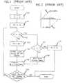
- FIG.1is a flow chart of a conventional automatic frequency tuning method
- FIG.2is a state diagram of the frequency tuning according to the flow chart shown in FIG.1
- FIG.3is a block diagram of a VTR, which is a diagram of the circuit for carrying out the flow chart shown in FIG.1.
- a microcomputer 300controls and processes the system.
- a key input means 310which may be a keyboard, a remote controlled receiver, etc. receives an order for the function selected by a viewer, information about channels, and any other needed control information, and then transfers it to the microcomputer 300 in the form of keyed input data.
- a tuner 320After selecting an arbitrary frequency band radio frequency signal among a radio frequency (hereinafter, referred to as "RF") signal entering into the RF converter 350 under the control of the microcomputer 300, a tuner 320 frequency-converts the selected radio frequency signal and supplies the frequency-converted intermediate frequency signal to the demodulator 330.
- RFradio frequency
- the demodulator 330demodulates the intermediate frequency signal supplied from the tuner 320, and supplies the demodulated video and audio signals to the signal processor 340, and generates an automatic frequency tuning signal having different logic states according to the magnitudes of the frequency of the intermediate frequency signal and the reference demodulation frequency, and then supplies the automatic frequency tuning signal to the microcomputer 300.
- the signal processor 340records video and audio signals entering from the demodulator 330 on a recording medium or reproduces the video and audio signals recorded on the recording medium to be supplied to a radio frequency converter 350.
- the RF converter 350modulates the video and audio signals entering from the signal processor 340 into radio frequency signals of the frequency band corresponding to television channels 3 or 4, to be output through connector OPT, and also outputs the radio frequency signal, received through the antenna ANT, through the connector OPT by a television / VTR mode selection switch, or supplies it to the tuner 320.
- a flow chart shown in FIG.1is carried out by the microcomputer 300 of the circuit shown in FIG.3, which is described with reference to the circuit shown in FIG.3 and the state diagram of the tuning frequency shown in FIG.2 as follows.
- the microcomputer 300When keyed data for channel information selected by a viewer is received from the key input means 310, the microcomputer 300 initiates a frequency search mode, flag X assigned in one of its registers as "0" to set a high frequency search mode such as 20 shown in FIG.2, and initiates a frequency increase number N stored in one of its registers as "0" (in step 100).
- the microcomputer 300After processing step 100, the microcomputer 300 reads out a reference search frequency fo for channel information corresponding to the input key data among reference search frequencies for respective channel information stored in its ROM, and then sets the read reference search frequency fo as a reference tuning control frequency fto, and then supplies the set reference tuning control frequency with a strobe signal of a low logic state to the tuner 320 according to a clock pulse train (in step 101).
- the microcomputer 300After carrying out step 101, the microcomputer 300 checks whether the frequency increase number N stored in one of its registers is equal to a limited increase number 32 (in step 102).
- the microcomputer 300adds "1" to the frequency increase number N (in step 103).
- the microcomputer 300After processing step 103, the microcomputer 300 stores a logic state of the automatic frequency tuning signal supplied from the demodulator 330 in its RAM (in step 104).
- the microcomputer 300After carrying out step 104, the microcomputer 300 multiplies the frequency increase number N by a unit frequency of 0.0625 MHz, and then adds the product to the reference tuning control frequency fto to set tuning control frequency ft, and then supplies the set tuning control frequency to the tuner 320 (in step 105).
- microcomputer 300After carrying out step 105, microcomputer 300 checks whether the logic state of the automatic frequency tuning signal entering from the demodulator 330 is equal to that of the automatic frequency tuning signal stored in its RAM, and if they are different from each other, completion of the tuning process is determined and the automatic frequency tuning operation is completed, and on the other hand, if they are equal, the microcomputer goes back to step 102 (in step 106).
- the microcomputer 300checks whether the frequency search mode flag X assigned in one of its registers is set to "1", thereby determining whether the low frequency search mode has been set (in step 107).
- the microcomputer 300sets the frequency search mode flag X to "1", so as to set a low frequency search mode such as 21 of FIG.2, and sets the set reference tuning control frequency fto, which has been set in step 101, to be smaller than the reference search frequency by 2 MHz, and initiates the frequency increase number N as "0", and then goes back to step 105 (in step 108).
- the microcomputer 300sets the reference search frequency fo as a tuning control frequency ft to be supplied to the tuner 320, and then completes the automatic frequency tuning operation (in step 109).
- the search mode of a frequency band lower than the reference search frequency fo corresponding to a channel by approximately 2 MHzis set in steps 100 and 101, and a broadcasting frequency for the channel is searched in the frequency band within 2 MHz from the reference search frequency according to the set search mode in step 102 to 106, and when the broadcasting frequency can not be found in the frequency band within ⁇ 2 MHz with reference to the reference search frequency, the reference search frequency is fixed and set as a tuning control frequency so as to complete the tuning operation in step 109.
- the conventional automatic frequency tuning methodsets low and high band search modes, and carries out a search process of 32 steps by an increase from the reference search frequency fo to each limited frequency fo ⁇ 2MHz by a constant frequency according to each set mode, without regarding the relation between the currently tuned radio frequency signal frequency and the active broadcasting frequency.
- the search process of 64 stepsis carried out to tune the broadcasting frequency, requiring an extensive amount of time to execute the frequency tuning process.
- US-A-4 763 195discloses a tuning system for tuning non-standard frequency RF television signals provided by cable distribution networks and television accessories conducting first and second consecutive searches by changing the local oscillator frequency.
- the first searchis limited to search frequencies corresponding to predictable non-standard frequencies associated with the major cable distribution networks.
- the second searchincludes more search frequencies and extends over a wider frequency range than the first.
- an auto-programming modein which active channels are identified, for memorization in a channel list portion of a memory, only the first search is conducted to minimize the required time.
- a method for controlling a tuner in a video receiving apparatus provided with a tuner for tuning a radio frequency signal from a plurality of radio frequency signals received through an antennais as defined in claim 1.
- a reference search frequency setting processis carried out in steps 400 and 401, and a tuning frequency search process is carried out in steps 402 to 408, and a compulsive tuning process corresponds to step 409.
- FIGS.5A and 5Bare state diagrams of frequency tuning according to the flow chart shown in FIG.4, FIG.5A is a state diagram of frequency tuning when the reference search frequency fo is lower than an active broadcasting frequency, and FIG.5B is a state diagram of frequency tuning when the reference search frequency fo is higher than the active broadcasting frequency.
- the flowchart shown in FIG.4is processed by microcomputer 300 of the diagram shown in FIG.3, and also microcomputer 300 of the diagram shown in FIG.3 processes the flow chart shown in FIG.4, when keyed data for channel information is received from key input means 310. And the flowcharted program shown in FIG.4 is stored in the ROM of microcomputer 300, and also the reference search frequencies fo for respective channels are stored in the ROM of microcomputer 300.
- the microcomputer 300initiates a frequency increase number N assigned to one of its registers as "0", when keyed data for channel information selected by a viewer is input from the key input means 310 (in step 400).
- microcomputer 300After processing step 400, microcomputer 300 reads out the reference search frequency fo corresponding to the channel information selected by the keyed input data among the reference search frequencies fo, for respective channel information stored in its ROM, and sets the read reference search frequency as a tuning control frequency ft, and then supplies the set tuning control frequency ft to the tuner 320 (in step 401).
- step 401the microcomputer 300 checks whether the frequency increase number N stored in one of its registers is equal to the limited increase number 32 (in step 402).
- the microcomputer 300increases the frequency increase number N by "1" (in step 403).
- microcomputer 300compares the current logic state of the automatic frequency tuning signal entering from the demodulator 330 with that of the previous automatic frequency tuning signal assigned to its register, and when the compared logic states are different from each other, the completion of the tuning process is determined and completes the operation (in step 404).
- step 404When the current logic state of the automatic frequency tuning signal is equal to that of the previous automatic frequency tuning signal in step 404, it is checked whether the logic state of the automatic frequency tuning signal entering from the demodulator 330 is in a high logic state, to determine whether the frequency of the radio frequency signal tuned by the tuning control frequency is higher than the active broadcasting frequency (in step 405).
- microcomputer 300sets the search direction mode flag X initially assigned to one of its registers as "-1" to a low band search mode (in step 406).
- microcomputer 300sets the search direction mode flag X assigned to one of its registers as "1" to a high band search mode (in step 407).
- microcomputer 300After carrying out step 406 or step 407, microcomputer 300 multiplies the frequency increase number N by a constant increase frequency of 0.0625 MHz, and then subtracts the product from the reference search frequency or adds the product to the reference search frequency according to the logic state of the search direction mode flag X set in step 406 or step 407 so as to set the tuning control frequency, and then supplies the set tuning control frequency to the tuner 320, and then goes back to the step 402 (in step 408).
- microcomputer 300sets the reference search frequency fo corresponding to the selected channel as a tuning control frequency ft, and then supplies the set tuning control frequency to the tuner 320, thereby completing the tuning operation (in step 409).
- the flow chart shown in FIG.4checks whether the frequency of the radio frequency signal tuned by the reference search frequency corresponding to the channel information selected at the beginning is greater than the active broadcasting frequency, and then searches the broadcasting frequency by moving the tuning control frequency by a constant amount in one direction to the limited frequency fo ⁇ 2MHz of the low band as shown in FIG.5B or of the high band as shown in FIG.5A with respect to the reference search frequency.
- the present inventioncompares the magnitudes between the selected radio frequency signal frequency and the active broadcasting frequency, and tunes the active broadcasting frequency by moving the tuning control frequency in one direction of the low or high band directions with respect to the reference search frequency corresponding to the channel selected by the viewer according to the compared result, so that there is an advantage in reducing time needed to execute the automatic frequency tuning process.
Landscapes
- Engineering & Computer Science (AREA)
- Signal Processing (AREA)
- Multimedia (AREA)
- Computer Hardware Design (AREA)
- Microelectronics & Electronic Packaging (AREA)
- Computer Networks & Wireless Communication (AREA)
- Channel Selection Circuits, Automatic Tuning Circuits (AREA)
- Television Receiver Circuits (AREA)
Description
- The present invention relates to a method for controlling a tuner in a video receiving apparatus, and more particularly to the method for carrying out frequency tuning at a high speed.
- Generally, a video receiving apparatus is an apparatus for receiving and displaying a video program transmitted from a broadcasting station through the air, and as a typical example, there is a television, a video tape recorder (hereinafter, referred to as a "VTR"), etc.
- Accordingly, a small-sized processor that has recently been developed and is commonly used in televisions or VTRs adds additional functions for increasing the convenience of the viewer using the processor and each circuit tends to be controlled by the processor.
- Accordingly, the video receiving apparatus has been converted so that the tuning of the broadcasting frequency for the broadcasting channel selected by a viewer is automatically carried out by the processor.
- However, up to now, the automatic frequency tuning method used in the video receiving apparatus has a problem of requiring an extensive amount of time to execute the frequency tuning process, which will be described with reference to the attached drawings FIGS.1 to 3.
- FIG.1 is a flow chart of a conventional automatic frequency tuning method, FIG.2 is a state diagram of the frequency tuning according to the flow chart shown in FIG.1, and FIG.3 is a block diagram of a VTR, which is a diagram of the circuit for carrying out the flow chart shown in FIG.1.
- For convenience, the circuit shown in FIG.3 will be described. A
microcomputer 300 controls and processes the system. And a key input means 310 which may be a keyboard, a remote controlled receiver, etc. receives an order for the function selected by a viewer, information about channels, and any other needed control information, and then transfers it to themicrocomputer 300 in the form of keyed input data. After selecting an arbitrary frequency band radio frequency signal among a radio frequency (hereinafter, referred to as "RF") signal entering into theRF converter 350 under the control of themicrocomputer 300, atuner 320 frequency-converts the selected radio frequency signal and supplies the frequency-converted intermediate frequency signal to thedemodulator 330. Thedemodulator 330 demodulates the intermediate frequency signal supplied from thetuner 320, and supplies the demodulated video and audio signals to thesignal processor 340, and generates an automatic frequency tuning signal having different logic states according to the magnitudes of the frequency of the intermediate frequency signal and the reference demodulation frequency, and then supplies the automatic frequency tuning signal to themicrocomputer 300. Thesignal processor 340 records video and audio signals entering from thedemodulator 330 on a recording medium or reproduces the video and audio signals recorded on the recording medium to be supplied to aradio frequency converter 350. TheRF converter 350 modulates the video and audio signals entering from thesignal processor 340 into radio frequency signals of the frequency band corresponding to television channels 3 or 4, to be output through connector OPT, and also outputs the radio frequency signal, received through the antenna ANT, through the connector OPT by a television / VTR mode selection switch, or supplies it to thetuner 320. - A flow chart shown in FIG.1 is carried out by the
microcomputer 300 of the circuit shown in FIG.3, which is described with reference to the circuit shown in FIG.3 and the state diagram of the tuning frequency shown in FIG.2 as follows. - When keyed data for channel information selected by a viewer is received from the key input means 310, the
microcomputer 300 initiates a frequency search mode, flag X assigned in one of its registers as "0" to set a high frequency search mode such as 20 shown in FIG.2, and initiates a frequency increase number N stored in one of its registers as "0" (in step 100). - After processing
step 100, themicrocomputer 300 reads out a reference search frequency fo for channel information corresponding to the input key data among reference search frequencies for respective channel information stored in its ROM, and then sets the read reference search frequency fo as a reference tuning control frequency fto, and then supplies the set reference tuning control frequency with a strobe signal of a low logic state to thetuner 320 according to a clock pulse train (in step 101). - After carrying out
step 101, themicrocomputer 300 checks whether the frequency increase number N stored in one of its registers is equal to a limited increase number 32 (in step 102). - when the frequency increase number N is not equal to the
limited increase number 32 instep 102, themicrocomputer 300 adds "1" to the frequency increase number N (in step 103). - After processing
step 103, themicrocomputer 300 stores a logic state of the automatic frequency tuning signal supplied from thedemodulator 330 in its RAM (in step 104). - After carrying out
step 104, themicrocomputer 300 multiplies the frequency increase number N by a unit frequency of 0.0625 MHz, and then adds the product to the reference tuning control frequency fto to set tuning control frequency ft, and then supplies the set tuning control frequency to the tuner 320 (in step 105). - After carrying out
step 105,microcomputer 300 checks whether the logic state of the automatic frequency tuning signal entering from thedemodulator 330 is equal to that of the automatic frequency tuning signal stored in its RAM, and if they are different from each other, completion of the tuning process is determined and the automatic frequency tuning operation is completed, and on the other hand, if they are equal, the microcomputer goes back to step 102 (in step 106). - And when the frequency increase number N is the
limited increase number 32 instep 102, themicrocomputer 300 checks whether the frequency search mode flag X assigned in one of its registers is set to "1", thereby determining whether the low frequency search mode has been set (in step 107). - When the frequency search mode flag X is reset to "0" in
step 107, i.e., when it is a high frequency search mode such as 20 of FIG.2, themicrocomputer 300 sets the frequency search mode flag X to "1", so as to set a low frequency search mode such as 21 of FIG.2, and sets the set reference tuning control frequency fto, which has been set instep 101, to be smaller than the reference search frequency by 2 MHz, and initiates the frequency increase number N as "0", and then goes back to step 105 (in step 108). - Inversely, when the frequency search mode flag X is set to "1" in
step 107, i.e. when a low frequency search mode is set, themicrocomputer 300 sets the reference search frequency fo as a tuning control frequency ft to be supplied to thetuner 320, and then completes the automatic frequency tuning operation (in step 109). - Thus, as indicated by the flow chart shown in FIG.1, the search mode of a frequency band lower than the reference search frequency fo corresponding to a channel by approximately 2 MHz is set in
steps step 102 to 106, and when the broadcasting frequency can not be found in the frequency band within ± 2 MHz with reference to the reference search frequency, the reference search frequency is fixed and set as a tuning control frequency so as to complete the tuning operation instep 109. - As described above with reference to FIGS.1 to 3, the conventional automatic frequency tuning method sets low and high band search modes, and carries out a search process of 32 steps by an increase from the reference search frequency fo to each limited frequency fo± 2MHz by a constant frequency according to each set mode, without regarding the relation between the currently tuned radio frequency signal frequency and the active broadcasting frequency. Thus, in the worst case, the search process of 64 steps is carried out to tune the broadcasting frequency, requiring an extensive amount of time to execute the frequency tuning process.
- US-A-4 763 195 discloses a tuning system for tuning non-standard frequency RF television signals provided by cable distribution networks and television accessories conducting first and second consecutive searches by changing the local oscillator frequency. The first search is limited to search frequencies corresponding to predictable non-standard frequencies associated with the major cable distribution networks. The second search includes more search frequencies and extends over a wider frequency range than the first. During an auto-programming mode, in which active channels are identified, for memorization in a channel list portion of a memory, only the first search is conducted to minimize the required time.
- Accordingly, it is an object of the present invention to provide a high speed automatic frequency tuning method which can carry out the frequency tuning process at a high speed in a video receiving apparatus.
- To achieve the object, according to the present invention, a method for controlling a tuner in a video receiving apparatus provided with a tuner for tuning a radio frequency signal from a plurality of radio frequency signals received through an antenna is as defined in
claim 1. - The above object and other advantages of the present invention will become more apparent by by describing the preferred embodiment of the present invention with reference to the attached drawings, in which:
- FIG.1 is a flow chart showing a conventional automatic frequency tuning method;
- FIG.2 is a state diagram of frequency tuning according to the flow chart shown in FIG.1;
- FIG.3 is a diagram of a circuit for carrying out the flow chart shown in FIG.1;
- FIG.4 is a flow chart of an embodiment of the high speed automatic frequency tuning method according to the present invention; and
- FIG.5 is a state diagram of frequency tuning according to the flow chart shown in FIG.4.
- With reference to FIG.4 which is a flow chart of the high speed automatic frequency tuning method of the present invention, a reference search frequency setting process is carried out in
steps steps 402 to 408, and a compulsive tuning process corresponds tostep 409. - FIGS.5A and 5B are state diagrams of frequency tuning according to the flow chart shown in FIG.4, FIG.5A is a state diagram of frequency tuning when the reference search frequency fo is lower than an active broadcasting frequency, and FIG.5B is a state diagram of frequency tuning when the reference search frequency fo is higher than the active broadcasting frequency.
- Successively, the flow chart shown in FIG.4 will be described in conjunction with the circuit diagram shown in FIG.3 and the frequency tuning state diagram shown in FIG.5.
- The flowchart shown in FIG.4 is processed by
microcomputer 300 of the diagram shown in FIG.3, and alsomicrocomputer 300 of the diagram shown in FIG.3 processes the flow chart shown in FIG.4, when keyed data for channel information is received fromkey input means 310. And the flowcharted program shown in FIG.4 is stored in the ROM ofmicrocomputer 300, and also the reference search frequencies fo for respective channels are stored in the ROM ofmicrocomputer 300. - The
microcomputer 300 initiates a frequency increase number N assigned to one of its registers as "0", when keyed data for channel information selected by a viewer is input from the key input means 310 (in step 400). - After processing
step 400,microcomputer 300 reads out the reference search frequency fo corresponding to the channel information selected by the keyed input data among the reference search frequencies fo, for respective channel information stored in its ROM, and sets the read reference search frequency as a tuning control frequency ft, and then supplies the set tuning control frequency ft to the tuner 320 (in step 401). - After carrying out
step 401, themicrocomputer 300 checks whether the frequency increase number N stored in one of its registers is equal to the limited increase number 32 (in step 402). - When the frequency increase number N is not equal to the
limited increase number 32 instep 402, themicrocomputer 300 increases the frequency increase number N by "1" (in step 403). - After processing
step 403,microcomputer 300 compares the current logic state of the automatic frequency tuning signal entering from thedemodulator 330 with that of the previous automatic frequency tuning signal assigned to its register, and when the compared logic states are different from each other, the completion of the tuning process is determined and completes the operation (in step 404). - When the current logic state of the automatic frequency tuning signal is equal to that of the previous automatic frequency tuning signal in
step 404, it is checked whether the logic state of the automatic frequency tuning signal entering from thedemodulator 330 is in a high logic state, to determine whether the frequency of the radio frequency signal tuned by the tuning control frequency is higher than the active broadcasting frequency (in step 405). - When the logic state of the automatic frequency tuning signal entering from the
demodulator 330 is recognized as being in a high logic state viastep 405, i.e. when the frequency of the radio frequency signal tuned by the tuning control frequency is higher than the active broadcasting frequency,microcomputer 300 sets the search direction mode flag X initially assigned to one of its registers as "-1" to a low band search mode (in step 406). - When the logic state of the automatic frequency tuning signal entering from the
demodulator 330 is recognized as being in a low logic state viastep 405, i.e. when the the frequency of the radio frequency signal tuned by the tuning control frequency is lower than the active broadcasting frequency,microcomputer 300 sets the search direction mode flag X assigned to one of its registers as "1" to a high band search mode (in step 407). - After carrying out
step 406 orstep 407,microcomputer 300 multiplies the frequency increase number N by a constant increase frequency of 0.0625 MHz, and then subtracts the product from the reference search frequency or adds the product to the reference search frequency according to the logic state of the search direction mode flag X set instep 406 orstep 407 so as to set the tuning control frequency, and then supplies the set tuning control frequency to thetuner 320, and then goes back to the step 402 (in step 408). - On the other hand, when the frequency increase number N is equal to the
limited increase number 32 instep 402,microcomputer 300 sets the reference search frequency fo corresponding to the selected channel as a tuning control frequency ft, and then supplies the set tuning control frequency to thetuner 320, thereby completing the tuning operation (in step 409). - In conclusion, the flow chart shown in FIG.4 checks whether the frequency of the radio frequency signal tuned by the reference search frequency corresponding to the channel information selected at the beginning is greater than the active broadcasting frequency, and then searches the broadcasting frequency by moving the tuning control frequency by a constant amount in one direction to the limited frequency fo± 2MHz of the low band as shown in FIG.5B or of the high band as shown in FIG.5A with respect to the reference search frequency.
- As described above, the present invention compares the magnitudes between the selected radio frequency signal frequency and the active broadcasting frequency, and tunes the active broadcasting frequency by moving the tuning control frequency in one direction of the low or high band directions with respect to the reference search frequency corresponding to the channel selected by the viewer according to the compared result, so that there is an advantage in reducing time needed to execute the automatic frequency tuning process.
Claims (1)
- A method for controlling a tuner in a video receiving apparatus for tuning a radio frequency signal from a plurality of radio frequency signals received through an antenna, comprising:a reference search frequency setting step for setting a reference search frequency (fo) corresponding to a broadcasting channel selected by a viewer as a tuning control frequency (ft) to enable the tuner to tune to a radio search frequency;a tuning frequency search step for making a determination of whether a frequency of the radio frequency signal tuned in by said tuner is greater than or less than a broadcasting frequency of the selected broadcasting channel, and moving the tuning control frequency (ft) within a predetermined number of frequency steps in one of an increasing direction and a decreasing direction from said reference search frequency (fo), until the frequency of the radio frequency signal tuned by the tuner is equal to the broadcasting channel, in dependence of said determination, to thereby enable the tuner to tune to the radio frequency signal corresponding to the tuning control frequency; anda compulsive tuning step for controlling said tuner to tune to the radio frequency signal of said reference search frequency corresponding to the selected broadcasting channel when the frequency of the radio frequency signal tuned by the tuner is not equal to the broadcasting frequency when the tuning control frequency reaches a limited frequency defined by the predetermined number of frequency steps in said tuning frequency search step.
Applications Claiming Priority (2)
| Application Number | Priority Date | Filing Date | Title |
|---|---|---|---|
| KR906048 | 1990-04-28 | ||
| KR1019900006048AKR920009877B1 (en) | 1990-04-28 | 1990-04-28 | High speed automatic frequency tuning method |
Publications (3)
| Publication Number | Publication Date |
|---|---|
| EP0455046A2 EP0455046A2 (en) | 1991-11-06 |
| EP0455046A3 EP0455046A3 (en) | 1993-12-15 |
| EP0455046B1true EP0455046B1 (en) | 1997-09-24 |
Family
ID=19298497
Family Applications (1)
| Application Number | Title | Priority Date | Filing Date |
|---|---|---|---|
| EP91106120AExpired - LifetimeEP0455046B1 (en) | 1990-04-28 | 1991-04-17 | High speed automatic frequency tuning method |
Country Status (5)
| Country | Link |
|---|---|
| US (1) | US5280640A (en) |
| EP (1) | EP0455046B1 (en) |
| JP (1) | JPH04229711A (en) |
| KR (1) | KR920009877B1 (en) |
| DE (1) | DE69127717T2 (en) |
Families Citing this family (12)
| Publication number | Priority date | Publication date | Assignee | Title |
|---|---|---|---|---|
| KR950001574B1 (en)* | 1992-02-29 | 1995-02-25 | 삼성전자주식회사 | Hrc mode receiving time reduction method of catv |
| KR960004515B1 (en)* | 1993-06-08 | 1996-04-06 | 엘지전자주식회사 | TV's automatic tuning range extension device and method |
| CA2222691A1 (en)* | 1995-06-06 | 1996-12-12 | Flash Comm, Inc. | Determining propagating and clear frequency in wireless data communications network |
| US5589844A (en)* | 1995-06-06 | 1996-12-31 | Flash Comm, Inc. | Automatic antenna tuner for low-cost mobile radio |
| US5765112A (en)* | 1995-06-06 | 1998-06-09 | Flash Comm. Inc. | Low cost wide area network for data communication using outbound message specifying inbound message time and frequency |
| US5734963A (en)* | 1995-06-06 | 1998-03-31 | Flash Comm, Inc. | Remote initiated messaging apparatus and method in a two way wireless data communications network |
| JP3068428U (en)* | 1999-10-22 | 2000-05-12 | 船井電機株式会社 | Television receiver |
| EP1104104A3 (en)* | 1999-11-23 | 2003-05-14 | Koninklijke Philips Electronics N.V. | Method for controlling a phase locked loop |
| US7738610B2 (en)* | 2005-08-31 | 2010-06-15 | Honeywell International Inc. | Method and apparatus for automatic alignment of notch filters |
| US8046015B2 (en)* | 2007-07-20 | 2011-10-25 | General Instrument Corporation | Adaptive tuning to improve demodulator performance |
| EP2583212B1 (en)* | 2010-06-16 | 2019-08-14 | OneSpan International GmbH | Mass storage device memory encryption methods, systems, and apparatus |
| US12067233B2 (en) | 2022-07-14 | 2024-08-20 | Samsung Electronics Co., Ltd. | Method and system for tuning a memory device for high-speed transitions |
Family Cites Families (11)
| Publication number | Priority date | Publication date | Assignee | Title |
|---|---|---|---|---|
| US4271434A (en)* | 1978-05-17 | 1981-06-02 | Matsushita Electric Industrial Co., Ltd. | Channel selector |
| US4397038A (en)* | 1979-03-26 | 1983-08-02 | Matsushita Electric Corporation Of America | Frequency synthesizer tuning system for television receivers |
| JPS5732123A (en)* | 1980-08-05 | 1982-02-20 | Toshiba Corp | Channel selector |
| US4364094A (en)* | 1981-05-08 | 1982-12-14 | Rca Corporation | Digital arrangement for detecting a correct television synchronization signal output useful in a signal seeking tuning system |
| US4357632A (en)* | 1981-05-08 | 1982-11-02 | Rca Corporation | Search type tuning system with synchronization signal presence transition detector |
| US4429415A (en)* | 1981-11-30 | 1984-01-31 | Rca Corporation | Signal-seeking tuning system with signal loss protection for a television receiver |
| JPS59178013A (en)* | 1983-03-29 | 1984-10-09 | Pioneer Electronic Corp | Method for selecting channel of receiver |
| JPS635669A (en)* | 1986-06-25 | 1988-01-11 | Mitsubishi Electric Corp | Channel selection device |
| JP2685744B2 (en)* | 1986-08-20 | 1997-12-03 | 三菱電機株式会社 | TV signal selection device |
| US4763195A (en)* | 1987-05-08 | 1988-08-09 | Rca Licensing Corporation | Television tuning system with provisions for quickly locating active cable channels |
| US4897727A (en)* | 1988-05-09 | 1990-01-30 | Thomson Consumer Electronics, Inc. | Television tuning system allowing rapid response to user initiated commands |
- 1990
- 1990-04-28KRKR1019900006048Apatent/KR920009877B1/ennot_activeExpired
- 1991
- 1991-04-15USUS07/684,794patent/US5280640A/ennot_activeExpired - Lifetime
- 1991-04-17EPEP91106120Apatent/EP0455046B1/ennot_activeExpired - Lifetime
- 1991-04-17DEDE69127717Tpatent/DE69127717T2/ennot_activeExpired - Lifetime
- 1991-04-24JPJP3094198Apatent/JPH04229711A/enactivePending
Also Published As
| Publication number | Publication date |
|---|---|
| JPH04229711A (en) | 1992-08-19 |
| KR920009877B1 (en) | 1992-11-02 |
| DE69127717D1 (en) | 1997-10-30 |
| EP0455046A3 (en) | 1993-12-15 |
| DE69127717T2 (en) | 1998-05-07 |
| EP0455046A2 (en) | 1991-11-06 |
| KR910019430A (en) | 1991-11-30 |
| US5280640A (en) | 1994-01-18 |
Similar Documents
| Publication | Publication Date | Title |
|---|---|---|
| US5087977A (en) | Channel selecting apparatus automatically detecting different modes of television signals | |
| US5323234A (en) | Programmable CATV system and terminal unit therefor | |
| US5283653A (en) | Dual HDTV/NTSC receiver using sequentially synthesized HDTV and NTSC co-channel carrier frequencies | |
| EP0455046B1 (en) | High speed automatic frequency tuning method | |
| US5418621A (en) | Circuit for detecting TV/radio broadcasting program, auto-tuning to channel selection and controlling VCR tape in recording operation | |
| KR20000068086A (en) | Receiver and receiving method | |
| US5299011A (en) | Method of and apparatus for channel scanning | |
| CA1288860C (en) | Television tuning system with provisions for tuning rf signals with scrambled video information | |
| US5329364A (en) | Method for reducing HRC mode reception time in cable television | |
| US5771080A (en) | Television signal tuning device | |
| US7206498B2 (en) | Recorder | |
| KR20010012939A (en) | Automatic installation | |
| KR0153728B1 (en) | Auto channel agreement method | |
| JP3969828B2 (en) | RF converter output channel automatic setting device, video tuner device and VTR for television signal receiver | |
| JPH01157680A (en) | Output frequency automatic selector for rf modulator | |
| KR0126797B1 (en) | Broadcasting method automatic selection method and device | |
| KR0135596B1 (en) | Broadcasting area automatic distinction | |
| JP3281690B2 (en) | Method for judging presence / absence of broadcast station and television receiver using the same | |
| KR950014334B1 (en) | Channel information store method & apparatus in tv/hdtv | |
| KR950007721Y1 (en) | Improved Channel Search Tuning System for TVCRs with Two Tuners | |
| KR920010321B1 (en) | Tunning method of catv | |
| KR100249804B1 (en) | How to set VRF's RF modulation channel automatically | |
| JPH10233970A (en) | Method for discriminating ground wave television broadcast and catv broadcast | |
| JPH10224703A (en) | Channel setting circuit for television receiver | |
| JPS61257025A (en) | Receiver |
Legal Events
| Date | Code | Title | Description |
|---|---|---|---|
| PUAI | Public reference made under article 153(3) epc to a published international application that has entered the european phase | Free format text:ORIGINAL CODE: 0009012 | |
| AK | Designated contracting states | Kind code of ref document:A2 Designated state(s):DE GB IT NL | |
| PUAL | Search report despatched | Free format text:ORIGINAL CODE: 0009013 | |
| AK | Designated contracting states | Kind code of ref document:A3 Designated state(s):DE GB IT NL | |
| 17P | Request for examination filed | Effective date:19940224 | |
| 17Q | First examination report despatched | Effective date:19960207 | |
| GRAG | Despatch of communication of intention to grant | Free format text:ORIGINAL CODE: EPIDOS AGRA | |
| GRAH | Despatch of communication of intention to grant a patent | Free format text:ORIGINAL CODE: EPIDOS IGRA | |
| GRAH | Despatch of communication of intention to grant a patent | Free format text:ORIGINAL CODE: EPIDOS IGRA | |
| GRAA | (expected) grant | Free format text:ORIGINAL CODE: 0009210 | |
| AK | Designated contracting states | Kind code of ref document:B1 Designated state(s):DE GB IT NL | |
| ITF | It: translation for a ep patent filed | ||
| REF | Corresponds to: | Ref document number:69127717 Country of ref document:DE Date of ref document:19971030 | |
| PLBE | No opposition filed within time limit | Free format text:ORIGINAL CODE: 0009261 | |
| STAA | Information on the status of an ep patent application or granted ep patent | Free format text:STATUS: NO OPPOSITION FILED WITHIN TIME LIMIT | |
| 26N | No opposition filed | ||
| REG | Reference to a national code | Ref country code:GB Ref legal event code:IF02 | |
| PGFP | Annual fee paid to national office [announced via postgrant information from national office to epo] | Ref country code:GB Payment date:20100325 Year of fee payment:20 | |
| PGFP | Annual fee paid to national office [announced via postgrant information from national office to epo] | Ref country code:NL Payment date:20100402 Year of fee payment:20 Ref country code:IT Payment date:20100417 Year of fee payment:20 Ref country code:DE Payment date:20100430 Year of fee payment:20 | |
| REG | Reference to a national code | Ref country code:DE Ref legal event code:R071 Ref document number:69127717 Country of ref document:DE | |
| REG | Reference to a national code | Ref country code:NL Ref legal event code:V4 Effective date:20110417 | |
| REG | Reference to a national code | Ref country code:GB Ref legal event code:PE20 Expiry date:20110416 | |
| PG25 | Lapsed in a contracting state [announced via postgrant information from national office to epo] | Ref country code:GB Free format text:LAPSE BECAUSE OF EXPIRATION OF PROTECTION Effective date:20110416 Ref country code:NL Free format text:LAPSE BECAUSE OF EXPIRATION OF PROTECTION Effective date:20110417 | |
| PG25 | Lapsed in a contracting state [announced via postgrant information from national office to epo] | Ref country code:DE Free format text:LAPSE BECAUSE OF EXPIRATION OF PROTECTION Effective date:20110417 |