EP0451996B1 - Reinforced medico-surgical tubes - Google Patents
Reinforced medico-surgical tubesDownload PDFInfo
- Publication number
- EP0451996B1 EP0451996B1EP91302731AEP91302731AEP0451996B1EP 0451996 B1EP0451996 B1EP 0451996B1EP 91302731 AEP91302731 AEP 91302731AEP 91302731 AEP91302731 AEP 91302731AEP 0451996 B1EP0451996 B1EP 0451996B1
- Authority
- EP
- European Patent Office
- Prior art keywords
- tube
- distal end
- filament
- face
- helix
- Prior art date
- Legal status (The legal status is an assumption and is not a legal conclusion. Google has not performed a legal analysis and makes no representation as to the accuracy of the status listed.)
- Expired - Lifetime
Links
- 238000000034methodMethods0.000claimsdescription27
- 239000000463materialSubstances0.000claimsdescription19
- 239000004033plasticSubstances0.000claimsdescription18
- 229920003023plasticPolymers0.000claimsdescription18
- 238000002844meltingMethods0.000claimsdescription7
- 230000008018meltingEffects0.000claimsdescription7
- 238000001816coolingMethods0.000claimsdescription3
- 238000007493shaping processMethods0.000claims1
- 238000004519manufacturing processMethods0.000description9
- 239000002184metalSubstances0.000description8
- 229910052751metalInorganic materials0.000description8
- 235000012489doughnutsNutrition0.000description4
- -1e.g.Substances0.000description3
- 239000004677NylonSubstances0.000description2
- 229920012485Plasticized Polyvinyl chloridePolymers0.000description2
- 238000001125extrusionMethods0.000description2
- 239000012530fluidSubstances0.000description2
- 239000003292glueSubstances0.000description2
- 229920001778nylonPolymers0.000description2
- 229920000139polyethylene terephthalatePolymers0.000description2
- 239000005020polyethylene terephthalateSubstances0.000description2
- 239000004814polyurethaneSubstances0.000description2
- 229920002635polyurethanePolymers0.000description2
- 229920002379silicone rubberPolymers0.000description2
- 239000004945silicone rubberSubstances0.000description2
- 229920000178Acrylic resinPolymers0.000description1
- 239000004925Acrylic resinSubstances0.000description1
- GUTLYIVDDKVIGB-OUBTZVSYSA-NCobalt-60Chemical compound[60Co]GUTLYIVDDKVIGB-OUBTZVSYSA-N0.000description1
- IAYPIBMASNFSPL-UHFFFAOYSA-NEthylene oxideChemical compoundC1CO1IAYPIBMASNFSPL-UHFFFAOYSA-N0.000description1
- 239000004743PolypropyleneSubstances0.000description1
- 239000004793PolystyreneSubstances0.000description1
- 238000007796conventional methodMethods0.000description1
- 230000008878couplingEffects0.000description1
- 238000010168coupling processMethods0.000description1
- 238000005859coupling reactionMethods0.000description1
- 230000002439hemostatic effectEffects0.000description1
- 238000002347injectionMethods0.000description1
- 239000007924injectionSubstances0.000description1
- 239000000155meltSubstances0.000description1
- 238000000465mouldingMethods0.000description1
- 230000000149penetrating effectEffects0.000description1
- WXZMFSXDPGVJKK-UHFFFAOYSA-NpentaerythritolChemical compoundOCC(CO)(CO)COWXZMFSXDPGVJKK-UHFFFAOYSA-N0.000description1
- 239000000049pigmentSubstances0.000description1
- 229920000728polyesterPolymers0.000description1
- 229920001155polypropylenePolymers0.000description1
- 229920002223polystyrenePolymers0.000description1
- 229920000915polyvinyl chloridePolymers0.000description1
- 239000004800polyvinyl chlorideSubstances0.000description1
- 230000005855radiationEffects0.000description1
- 230000002787reinforcementEffects0.000description1
- 230000003014reinforcing effectEffects0.000description1
- 238000000926separation methodMethods0.000description1
- 239000002904solventSubstances0.000description1
- 238000001356surgical procedureMethods0.000description1
- 210000003437tracheaAnatomy0.000description1
- 238000002627tracheal intubationMethods0.000description1
Images

Classifications
- A—HUMAN NECESSITIES
- A61—MEDICAL OR VETERINARY SCIENCE; HYGIENE
- A61M—DEVICES FOR INTRODUCING MEDIA INTO, OR ONTO, THE BODY; DEVICES FOR TRANSDUCING BODY MEDIA OR FOR TAKING MEDIA FROM THE BODY; DEVICES FOR PRODUCING OR ENDING SLEEP OR STUPOR
- A61M16/00—Devices for influencing the respiratory system of patients by gas treatment, e.g. ventilators; Tracheal tubes
- A61M16/04—Tracheal tubes
- A61M16/0402—Special features for tracheal tubes not otherwise provided for
- A61M16/0425—Metal tubes
- A—HUMAN NECESSITIES
- A61—MEDICAL OR VETERINARY SCIENCE; HYGIENE
- A61M—DEVICES FOR INTRODUCING MEDIA INTO, OR ONTO, THE BODY; DEVICES FOR TRANSDUCING BODY MEDIA OR FOR TAKING MEDIA FROM THE BODY; DEVICES FOR PRODUCING OR ENDING SLEEP OR STUPOR
- A61M25/00—Catheters; Hollow probes
- A61M25/0043—Catheters; Hollow probes characterised by structural features
- A61M25/005—Catheters; Hollow probes characterised by structural features with embedded materials for reinforcement, e.g. wires, coils, braids
- A—HUMAN NECESSITIES
- A61—MEDICAL OR VETERINARY SCIENCE; HYGIENE
- A61M—DEVICES FOR INTRODUCING MEDIA INTO, OR ONTO, THE BODY; DEVICES FOR TRANSDUCING BODY MEDIA OR FOR TAKING MEDIA FROM THE BODY; DEVICES FOR PRODUCING OR ENDING SLEEP OR STUPOR
- A61M2205/00—General characteristics of the apparatus
- A61M2205/32—General characteristics of the apparatus with radio-opaque indicia
- A—HUMAN NECESSITIES
- A61—MEDICAL OR VETERINARY SCIENCE; HYGIENE
- A61M—DEVICES FOR INTRODUCING MEDIA INTO, OR ONTO, THE BODY; DEVICES FOR TRANSDUCING BODY MEDIA OR FOR TAKING MEDIA FROM THE BODY; DEVICES FOR PRODUCING OR ENDING SLEEP OR STUPOR
- A61M25/00—Catheters; Hollow probes
- A61M25/0009—Making of catheters or other medical or surgical tubes
- A61M25/0012—Making of catheters or other medical or surgical tubes with embedded structures, e.g. coils, braids, meshes, strands or radiopaque coils
Definitions
- This inventionrelates to the manufacture of reinforced catheters, tracheal tubes, tracheotomy tubes and other medico-surgical tubes and to the resulting products. More particularly, it concerns the production of medico-surgical tubes that have a central body portion containing a helix of a rigid plastic filament that serves to strengthen the tubes so as to resist kinking and collapsing during use.
- This inventionrelates to uncuffed and balloon-type catheters, i.e., catheters which may be provided at the distal end with an inflatable balloon or cuff which serves, during the medical or surgical procedure performed using the catheter, to retain the catheter in a desired position within the patient, to seal a passage in the patient, etc.
- Medico-surgical tubesmay assume a variety of sizes, shapes and be provided with a variety of fluid openings, couplings, connectors or the like.
- Terminology applied to such devices by userse.g., physicians, surgeons, hospitals, etc., frequently refer to them as catheters, e.g., rectal catheters, urethral catheters, hemostatic catheters and the like, but in other cases they are referred to as tubes, e.g., endotracheal tubes, feeding tubes, suction tubes, drain tubes and the like.
- medico-surgical tubesthat comprise a lumen through which fluids may be passed to or from the body of a patient are known.
- the simplest of theseare the catheters (see U.S. Patent Nos. 2,437,542; 2,857,915; 3,485,234; 3,605,750; 3,618,613; and 4,210,478).
- More complex medico-surgical tubesinclude endotracheal tubes (see U.S. Patent Nos. 3,625,793; 3,684,605; 3,725,522 and 3,755,525), post surgical tubes (see U.S. Patent No. 3,589,368), tracheotomy tubes (see U.S. Patent No. 3,973,569), sump drain tubes (see U.S. Patent No.
- medico-surgical tubesIt is desirable with most types of medico-surgical tubes that they be flexible and have as thin a wall as possible. There is a trade-off, however, in constructing the medico-surgical tube with thin walls and high flexibility, i.e., the thinner and more flexible the tube, the greater the possibility the tube will kink or collapse during use. Since kinking or collapsing can result in complete closure of the lumen with attendant damage or death to the patient, medico-surgical tubes must be structured so as to mitigate kinking.
- Metal wire reinforced tubesare disadvantageous in that they will not spring back when partially collapsed. For instance, if a patient bites down on a metal wire reinforced tracheal tube, the metal wire would be deformed beyond its elastic limit such that the tube remains in a collapsed condition. Such collapsing of the tube can result in nearly complete closure of the lumen with attendant hazard to the patient. Filament reinforced tubes, on the other hand, are more resistant to kinking and crushing because they can spring back when collapsed.
- a continuous, extruded tubecan be square-cut at the proximal end and have a bevel or angle-cut at the distal end. In pure plastic without reinforcing this cutting is straight forward. Subsequent finishing of the distal end can be accomplished by pushing the angle cut end into a heated mold that melts the PVC and forms it into the shape of the mold (see U.S. Patent No. 3,725,522 and Canadian Patent No. 1,199,761). With this technique, the square edges of the angle cut tip can be made smooth and radiused. An eye can be punched through the long part of the distal end. This can be accomplished by placing a flat mandrel inside the tube and driving a cookie-cutter type punch through the wall.
- distal end finishing methods for reinforced tubesinclude placing a square-cut end into an injection mold, forming the complete tip purely of plastic and at the same time fusing it to the reinforced tube.
- a pure plastic (wire-free) tipcan be made by separately extruding pure plastic tubing of identical ID and OD to the reinforced tube and the tip can be secured to the tube section with solvent or glue.
- Another methodinvolves stripping of the wire out from between the tube inner and outer walls of a simple square-cut distal tip and the two walls can be welded together with glue after which the tip is then angle-cut, heat-mold finished, and eye punched. It may also be possible to provide spaced, helix or sheathing free portions (such as by intermittently stopping the coiling of filament or sheathing about a base tube) and the tube can be cut to form distal ends of the tube in the helix-free portions of the tube.
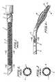
- a catheter similar to that shown in Fig. 1is disclosed in DE-A-867144.
- a prior art catheter 1 shown in Fig. 1comprises a molded, helix-free distal end 2, a molded, helix-free proximal end 3 and central body portion 4 containing a helix 5 (see Fig. 2).
- a small loop 6is formed in the distal end of helix 5 prior to forming the molded distal end 2 on the catheter 1.
- a rigid molded connector 7has its distal end 8 encircled by a slightly expanded proximal end 3 of the catheter 1.
- distal ends of reinforced medico-surgical tubesPrior to the present invention, the production of distal ends of reinforced medico-surgical tubes has been a labor intensive operation (see Canadian Patent No. 1199761 and GB 2043201A). Furthermore, such distal ends have heretofore been provided without reinforcement for increasing compressive strength of the distal ends.
- the present inventionconcerns improved methods for production of distal ends of rigid plastic filament reinforced medico-surgical tubes at lower costs and higher degree of uniformity of product than has been possible heretofore.
- a principal object of the present inventionis the provision of a novel reinforced medico-surgical tube and a new method for the production of the distal end of such a reinforced medico-surgical tube.
- An object of the present inventionis to provide a catheter that is filament reinforced all the way to the distal end (i.e. tip) thereof and finished in a manner smooth enough for intubation. It is expected that the invention will be of very great commercial value as it may replace all metal wire reinforced medical tubes, at least metal wire reinforced tracheal tubes.
- the non-metallic filament reinforced tube with smooth tip finish according to the inventionwill be superior in many cases and will be much more economical to produce than a metal wire reinforced tube.
- a medico-surgical tubeis reinforced with a filament helix such that a plurality of coils of the filament helix is provided at a distal end of the tube, the tube is simply angle cut or square cut to form the distal end without stripping or other operations, and then the distal end is finished with relatively simple methods.
- the medico-surgical tubecan comprise a filament reinforced tracheostomy or tracheal tube with the filament extending all the way to the end face at the distal end (hereinafter referred to as the distal end face or axial end face) and the distal end is finished in a simple manner.
- reinforced medico-surgical tubescan be made by a new method which comprises first extruding a continuous, flexible base tube, cooling the extruded tube, coiling a helix of filament about the cooled tube, then extruding an outer layer onto the helix and base tube to form a laminated final tube, cutting the final tube into sections of predetermined length and finally forming at least one filament containing distal end on each cut section of the final tube.
- the filament containing distal endmay be finished by inserting a donut-shaped piece of plastic in a heated mold prior to inserting the end of a cut section of the final tube in the mold and molding the piece of plastic onto the tube section whereby a radiused tip or end face is formed on the end of the tube.
- the filament containing endmay be finished by simply melting the filament containing distal end of a cut section of final tube.
- the medico-surgical tubes of the inventioncomprise a medico-surgical tube such as a tracheal tube 9 which includes a filament containing distal end 10 and a proximal end (not shown) joined together by a central body portion 11 (see Fig. 4).
- the tube 9has a major lumen that extends the entire length of the tube and can have a secondary lumen 12 formed in a wall 13 of tube 9 (see Fig. 5).
- the secondary lumen 12can open near its distal end into a balloon cuff 14 and can be connected at or near its proximal end to an inflation tube (not shown) provided with a pilot balloon (not shown) and a check valve (not shown).
- the central body portion 11 of the tube 9contains a filament helix 15 while the proximal end may be filament-free.
- the distal end 10includes means comprising a plurality of coils of the filament helix 15 for providing compressive strength of the distal end 10 as compared to a tube which does not contain such a filament helix.
- the tube 9can be made of flexible material, e.g., plasticized polyvinyl chloride, polyurethane, silicone rubber or similar material, while a connector element (not shown) attachable to the proximal end the tube 9 can be molded from rigid material, e.g., nylon, polypropylene, acrylic resin, polystyrene or the like.
- Tracheal tubessuch as tube 9 are made in a variety of sizes. Typically such tubes will be about 10 to 40 cm in length with the inner diameter (“I.D.”) of the major lumen between about 2.0 to 10.0 mm and with the outer diameter (“O.D.”) of about 2 to 3 mm greater than the diameter of the major lumen. Other types of tubes in accordance with the teachings of the invention will have dimensions suitable for the intended use of such tubes.
- the helix 15is preferably formed by a rigid plastic filament having a diameter of about 0.1 to 0.5 mm and the spacing between separate coils of the filament 15 typically can be such that the number of winds per tube diameter is generally over 1 and preferably is 5-10 winds per tube diameter. For instance for a 7 mm I.D. tube, the separation between the coils can be about 1 to 3 mm.
- the filament diameter and spacing between individual coilscan be varied to suit the intended use of the tube.
- Various types of rigid plastic filamentsmay be used to form the helix, e.g., nylon monofilaments, polyester filaments, poly(ethylene) terephthalate ("PETP", "PET”) and the like.
- a tracheal tubesuch as tube 9, according to the invention can be performed as follows. First, a continuous tube of flexible material, e.g., plasticized polyvinyl chloride, polyurethane, silicone rubber or the like is extruded. This base tube can have a wall thickness of about one-half the thickness desired in the final tube.
- flexible materiale.g., plasticized polyvinyl chloride, polyurethane, silicone rubber or the like.
- the extruded tubeis then cooled by passing it through a cooling bath as it emerges from the extrusion die.
- a filamentis coiled about the cooled tube to form a helix that runs longitudinally along the outer surface of the base tube.
- the helixcan be continuous along the entire length of the base tube.
- the assemblyis fed through a second extruder where an outer layer is extruded over the combined base tube and helix thereby forming a continuous flexible final tube comprising the helix laminated between the base tube and the outer layer, as shown in Fig. 5.
- at least one secondary lumen 12can be formed in the outer layer using a suitable die.
- the outer layermay be formed of the same material as the base layer. Alternatively, the outer and inner layers may be formed of different materials.
- the tube 9is reinforced with filament all the way to the tip, the tip is simply cut square with the end face lying in a plane at an angle of 90° to a central axis of the tube 9 or at an angle with the end face lying in a plane at an angle other than 90° to the central axis of the tube 9.
- the distal endcan be cut at an angle of about 45° as shown in Fig. 4 without stripping or other operations, and then the tip can be end finished with relatively simple methods.
- the method according to the present inventioncan thus include co-extruding filament reinforced tracheal tubing.
- the end finishing technique according to the inventionis economical and simple on such filament reinforced tubes since the ends of such tubes can be cut off using conventional techniques.
- the end finishing techniquemay involve melting the square-cut 16 or angle-cut 17 end either directly or by placing a small washer-shaped donut 18 (Figs. 6 and 7) of plastic in a mold (not shown) prior to inserting the distal end 10 of the final tube 9 in the mold.
- the piece 18can have a thickness in the axial direction A (Fig. 6) of about the wall thickness of the final tube and can comprise an annular section of a non-filament containing tube.
- the axial thickness of the piece 18should be enough to provide a thin layer which covers the exposed ends of the filament when the piece is melted.
- the piece 18covers the raw end or ends 19 of the chopped filament 15 which might otherwise be exposed as cutting edges as the tube 9 is inserted into a body opening such as a trachea.
- the addition of the plastic piece 18can be omitted, however, since the ends of the chopped filament can also be suitably covered by a thin layer of material simply by melting the extreme end face of the distal end 10 or by using any other suitable method.
- the donut of plastic 18it is also possible to incorporate X-ray opaque pigment therein whereby the opening in the tube can be seen in the body of a patient using X-ray methods.
- the reinforced medico-surgical tube of the inventionthus comprises a tube 9 of flexible material, a rigid plastic filament helix 15 coaxial with the tube and disposed between inner and outer peripheries of the tube with a plurality of coils of the helix being provided at a distal end 10 of the tube to increase the compressive strength of the distal end, the distal end including an axial end face 20.
- the individual coils of the filament helix 15are separated into a plurality of discrete pieces at the distal end 10 due to the cutting step.
- coils 21 of the filament helixare discontinuous with each other and the free ends 19 of the cut filament are exposed at the end face 20 after the cutting step (see Fig. 8).
- the respective discontinuous coils of the filamentbecome shorter in circumferential length at positions located closer to the axial end face 20, at least some of the discontinuous coils having free opposing ends 19 thereof confronting the axial end face 20 but being spaced inwardly therefrom by a thin layer of flexible material formed by melting the end face 20, by melting the plastic piece 18 onto the end face or by any other suitable method.
- the thin layercan have a maximum thickness between the end face 20 and a portion of the filament located closest thereto of about twice the distance between adjacent coils of the filament helix 15.
- the thin layercan have a maximum thickness of about four times the wall thickness of the tube.
- an opening or eye 22can extend between the inner and outer peripheries of the tube at the distal end 10 thereof.
- the inventionis proposed for use in manufacture of all types of reinforced medico-surgical tubes now used or later developed for use by the medical profession.
Landscapes
- Health & Medical Sciences (AREA)
- Pulmonology (AREA)
- Life Sciences & Earth Sciences (AREA)
- Anesthesiology (AREA)
- General Health & Medical Sciences (AREA)
- Biomedical Technology (AREA)
- Heart & Thoracic Surgery (AREA)
- Hematology (AREA)
- Veterinary Medicine (AREA)
- Animal Behavior & Ethology (AREA)
- Engineering & Computer Science (AREA)
- Public Health (AREA)
- Emergency Medicine (AREA)
- Biophysics (AREA)
- Materials For Medical Uses (AREA)
- Media Introduction/Drainage Providing Device (AREA)
- Surgical Instruments (AREA)
- Extrusion Moulding Of Plastics Or The Like (AREA)
Description
- This invention relates to the manufacture of reinforced catheters, tracheal tubes, tracheotomy tubes and other medico-surgical tubes and to the resulting products. More particularly, it concerns the production of medico-surgical tubes that have a central body portion containing a helix of a rigid plastic filament that serves to strengthen the tubes so as to resist kinking and collapsing during use.
- This invention relates to uncuffed and balloon-type catheters, i.e., catheters which may be provided at the distal end with an inflatable balloon or cuff which serves, during the medical or surgical procedure performed using the catheter, to retain the catheter in a desired position within the patient, to seal a passage in the patient, etc.
- Medico-surgical tubes may assume a variety of sizes, shapes and be provided with a variety of fluid openings, couplings, connectors or the like. Terminology applied to such devices by users, e.g., physicians, surgeons, hospitals, etc., frequently refer to them as catheters, e.g., rectal catheters, urethral catheters, hemostatic catheters and the like, but in other cases they are referred to as tubes, e.g., endotracheal tubes, feeding tubes, suction tubes, drain tubes and the like. For the sake of brevity in describing the improved devices of the invention and their method of production, the term "catheter" is employed throughout the specification and accompanying claims to encompass pertinent medicosurgical devices whether they be popularly referred to by the medical profession and other users as "catheters" or "tubes."
- Many forms of medico-surgical tubes that comprise a lumen through which fluids may be passed to or from the body of a patient are known. The simplest of these are the catheters (see U.S. Patent Nos. 2,437,542; 2,857,915; 3,485,234; 3,605,750; 3,618,613; and 4,210,478). More complex medico-surgical tubes include endotracheal tubes (see U.S. Patent Nos. 3,625,793; 3,684,605; 3,725,522 and 3,755,525), post surgical tubes (see U.S. Patent No. 3,589,368), tracheotomy tubes (see U.S. Patent No. 3,973,569), sump drain tubes (see U.S. Patent No. 3,314,430) tubes for urological use (see U.S. Patent No. 2,268,321) and esophogeal endoprosthesis tubes. The present invention provides an improved medico-surgical tube and a method for the production thereof, the medico-surgical tube having a novel distal end.
- It is desirable with most types of medico-surgical tubes that they be flexible and have as thin a wall as possible. There is a trade-off, however, in constructing the medico-surgical tube with thin walls and high flexibility, i.e., the thinner and more flexible the tube, the greater the possibility the tube will kink or collapse during use. Since kinking or collapsing can result in complete closure of the lumen with attendant damage or death to the patient, medico-surgical tubes must be structured so as to mitigate kinking.
- One way the industry has developed to provide medico-surgical tubes with increased strength but not necessarily with low kinking potential is to include in them a braided wire sheathing embedded between plastic layers (see Great Britain Patent Publication No. GB 2043201A) or a helix of metal wire or synthetic filament (see Canadian Patent No. 1,199,761). Such helix containing tubes are referred to in the trade as "reinforced." In the reinforced tubes, the spacings between coils of the helix are quite small, e.g., 1-3 mm, and are to be contrasted to catheters and like tubes comprising filaments to increase tensile or burst strength, rather than compressive strength (see U.S. Patent No. 2,268,321). The distal end of the catheter shown in Figs. 11-13 of U.S. Patent No. 2,268,321 is not reinforced by a filament helix such that a plurality of coils of the filament helix is provided in the distal end.
- Metal wire reinforced tubes, however, are disadvantageous in that they will not spring back when partially collapsed. For instance, if a patient bites down on a metal wire reinforced tracheal tube, the metal wire would be deformed beyond its elastic limit such that the tube remains in a collapsed condition. Such collapsing of the tube can result in nearly complete closure of the lumen with attendant hazard to the patient. Filament reinforced tubes, on the other hand, are more resistant to kinking and crushing because they can spring back when collapsed.
- Various methods are known in the art for producing a distal end on such medico-surgical tubes. For instance, a continuous, extruded tube can be square-cut at the proximal end and have a bevel or angle-cut at the distal end. In pure plastic without reinforcing this cutting is straight forward. Subsequent finishing of the distal end can be accomplished by pushing the angle cut end into a heated mold that melts the PVC and forms it into the shape of the mold (see U.S. Patent No. 3,725,522 and Canadian Patent No. 1,199,761). With this technique, the square edges of the angle cut tip can be made smooth and radiused. An eye can be punched through the long part of the distal end. This can be accomplished by placing a flat mandrel inside the tube and driving a cookie-cutter type punch through the wall.
- For extruded tracheal tubes reinforced with wire, however, complicated, and therefore costly end finishing methods have heretofore been used. (See GB 2043201A and Canadian Patent No. 1,199,761). For instance, distal end finishing methods for reinforced tubes include placing a square-cut end into an injection mold, forming the complete tip purely of plastic and at the same time fusing it to the reinforced tube. Alternatively, a pure plastic (wire-free) tip can be made by separately extruding pure plastic tubing of identical ID and OD to the reinforced tube and the tip can be secured to the tube section with solvent or glue. Another method involves stripping of the wire out from between the tube inner and outer walls of a simple square-cut distal tip and the two walls can be welded together with glue after which the tip is then angle-cut, heat-mold finished, and eye punched. It may also be possible to provide spaced, helix or sheathing free portions (such as by intermittently stopping the coiling of filament or sheathing about a base tube) and the tube can be cut to form distal ends of the tube in the helix-free portions of the tube.
- A catheter similar to that shown in Fig. 1 is disclosed in DE-A-867144.
- A prior art catheter 1 shown in Fig. 1 comprises a molded, helix-free
distal end 2, a molded, helix-freeproximal end 3 and central body portion 4 containing a helix 5 (see Fig. 2). In order to safeguard against the possibility of the distal end of the helix 5 (particularly where it is made of metal wire) penetrating the outer layer of the catheter 1 during its use, a small loop 6 (see Fig. 3) is formed in the distal end ofhelix 5 prior to forming the moldeddistal end 2 on the catheter 1. A rigid molded connector 7 has its distal end 8 encircled by a slightly expandedproximal end 3 of the catheter 1. - Prior to the present invention, the production of distal ends of reinforced medico-surgical tubes has been a labor intensive operation (see Canadian Patent No. 1199761 and GB 2043201A). Furthermore, such distal ends have heretofore been provided without reinforcement for increasing compressive strength of the distal ends. The present invention concerns improved methods for production of distal ends of rigid plastic filament reinforced medico-surgical tubes at lower costs and higher degree of uniformity of product than has been possible heretofore.
- A principal object of the present invention is the provision of a novel reinforced medico-surgical tube and a new method for the production of the distal end of such a reinforced medico-surgical tube.
- An object of the present invention is to provide a catheter that is filament reinforced all the way to the distal end (i.e. tip) thereof and finished in a manner smooth enough for intubation. It is expected that the invention will be of very great commercial value as it may replace all metal wire reinforced medical tubes, at least metal wire reinforced tracheal tubes. The non-metallic filament reinforced tube with smooth tip finish according to the invention will be superior in many cases and will be much more economical to produce than a metal wire reinforced tube.
- In a preferred embodiment, a medico-surgical tube is reinforced with a filament helix such that a plurality of coils of the filament helix is provided at a distal end of the tube, the tube is simply angle cut or square cut to form the distal end without stripping or other operations, and then the distal end is finished with relatively simple methods. In particular, the medico-surgical tube can comprise a filament reinforced tracheostomy or tracheal tube with the filament extending all the way to the end face at the distal end (hereinafter referred to as the distal end face or axial end face) and the distal end is finished in a simple manner.
- According to the present invention, reinforced medico-surgical tubes can be made by a new method which comprises first extruding a continuous, flexible base tube, cooling the extruded tube, coiling a helix of filament about the cooled tube, then extruding an outer layer onto the helix and base tube to form a laminated final tube, cutting the final tube into sections of predetermined length and finally forming at least one filament containing distal end on each cut section of the final tube.
- The filament containing distal end may be finished by inserting a donut-shaped piece of plastic in a heated mold prior to inserting the end of a cut section of the final tube in the mold and molding the piece of plastic onto the tube section whereby a radiused tip or end face is formed on the end of the tube. Alternatively, the filament containing end may be finished by simply melting the filament containing distal end of a cut section of final tube.
- The invention will now be described with reference to the drawings, in which:
- Fig. 1 is a lateral view of a prior art catheter;
- Fig. 2 is a sectional view taken on the line 2-2 of Fig. 1;
- Fig. 3 is a sectional view taken on the line 3-3 of Fig. 1;
- Fig. 4 is a fragmentary isometric view of a medico-surgical tube made in accordance with the invention;
- Fig. 5 is a sectional view taken on the line 5-5 of Fig. 4;
- Fig. 6 is a longitudinal cross-section of the tube according to the invention prior to finishing the distal end in a mold using a donut;
- Fig. 7 shows a cross-section of the donut taken along the line 7-7 in Fig. 6; and
- Fig. 8 shows a perspective view of the tube according to the invention prior to the end finishing step.
- The medico-surgical tubes of the invention comprise a medico-surgical tube such as a
tracheal tube 9 which includes a filament containingdistal end 10 and a proximal end (not shown) joined together by a central body portion 11 (see Fig. 4). Thetube 9 has a major lumen that extends the entire length of the tube and can have asecondary lumen 12 formed in awall 13 of tube 9 (see Fig. 5). Thesecondary lumen 12 can open near its distal end into aballoon cuff 14 and can be connected at or near its proximal end to an inflation tube (not shown) provided with a pilot balloon (not shown) and a check valve (not shown). - The central body portion 11 of the
tube 9 contains afilament helix 15 while the proximal end may be filament-free. Thedistal end 10, on the other hand, includes means comprising a plurality of coils of thefilament helix 15 for providing compressive strength of thedistal end 10 as compared to a tube which does not contain such a filament helix. Thetube 9 can be made of flexible material, e.g., plasticized polyvinyl chloride, polyurethane, silicone rubber or similar material, while a connector element (not shown) attachable to the proximal end thetube 9 can be molded from rigid material, e.g., nylon, polypropylene, acrylic resin, polystyrene or the like. - Tracheal tubes such as
tube 9 are made in a variety of sizes. Typically such tubes will be about 10 to 40 cm in length with the inner diameter ("I.D.") of the major lumen between about 2.0 to 10.0 mm and with the outer diameter ("O.D.") of about 2 to 3 mm greater than the diameter of the major lumen. Other types of tubes in accordance with the teachings of the invention will have dimensions suitable for the intended use of such tubes. - The
helix 15 is preferably formed by a rigid plastic filament having a diameter of about 0.1 to 0.5 mm and the spacing between separate coils of thefilament 15 typically can be such that the number of winds per tube diameter is generally over 1 and preferably is 5-10 winds per tube diameter. For instance for a 7 mm I.D. tube, the separation between the coils can be about 1 to 3 mm. The filament diameter and spacing between individual coils, however, can be varied to suit the intended use of the tube. Various types of rigid plastic filaments may be used to form the helix, e.g., nylon monofilaments, polyester filaments, poly(ethylene) terephthalate ("PETP", "PET") and the like. - The production of a tracheal tube, such as
tube 9, according to the invention can be performed as follows. First, a continuous tube of flexible material, e.g., plasticized polyvinyl chloride, polyurethane, silicone rubber or the like is extruded. This base tube can have a wall thickness of about one-half the thickness desired in the final tube. - The extruded tube is then cooled by passing it through a cooling bath as it emerges from the extrusion die. Next, a filament is coiled about the cooled tube to form a helix that runs longitudinally along the outer surface of the base tube. In accordance with the invention, the helix can be continuous along the entire length of the base tube. As the helix is wound around the base tube, the assembly is fed through a second extruder where an outer layer is extruded over the combined base tube and helix thereby forming a continuous flexible final tube comprising the helix laminated between the base tube and the outer layer, as shown in Fig. 5. During this second extrusion, at least one
secondary lumen 12 can be formed in the outer layer using a suitable die. The outer layer may be formed of the same material as the base layer. Alternatively, the outer and inner layers may be formed of different materials. - According to the invention, the
tube 9 is reinforced with filament all the way to the tip, the tip is simply cut square with the end face lying in a plane at an angle of 90° to a central axis of thetube 9 or at an angle with the end face lying in a plane at an angle other than 90° to the central axis of thetube 9. For instance, the distal end can be cut at an angle of about 45° as shown in Fig. 4 without stripping or other operations, and then the tip can be end finished with relatively simple methods. - The method according to the present invention can thus include co-extruding filament reinforced tracheal tubing. The end finishing technique according to the invention is economical and simple on such filament reinforced tubes since the ends of such tubes can be cut off using conventional techniques.
- The end finishing technique according to the invention may involve melting the square-
cut 16 or angle-cut 17 end either directly or by placing a small washer-shaped donut 18 (Figs. 6 and 7) of plastic in a mold (not shown) prior to inserting thedistal end 10 of thefinal tube 9 in the mold. In a preferred embodiment, thepiece 18 can have a thickness in the axial direction A (Fig. 6) of about the wall thickness of the final tube and can comprise an annular section of a non-filament containing tube. The axial thickness of thepiece 18 should be enough to provide a thin layer which covers the exposed ends of the filament when the piece is melted. Accordingly, after thepiece 18 is melted, it covers the raw end or ends 19 of the choppedfilament 15 which might otherwise be exposed as cutting edges as thetube 9 is inserted into a body opening such as a trachea. The addition of theplastic piece 18 can be omitted, however, since the ends of the chopped filament can also be suitably covered by a thin layer of material simply by melting the extreme end face of thedistal end 10 or by using any other suitable method. - If the donut of
plastic 18 is used, it is also possible to incorporate X-ray opaque pigment therein whereby the opening in the tube can be seen in the body of a patient using X-ray methods. - The reinforced medico-surgical tube of the invention thus comprises a
tube 9 of flexible material, a rigidplastic filament helix 15 coaxial with the tube and disposed between inner and outer peripheries of the tube with a plurality of coils of the helix being provided at adistal end 10 of the tube to increase the compressive strength of the distal end, the distal end including anaxial end face 20. In the case of the angle-cutend 17, the individual coils of thefilament helix 15 are separated into a plurality of discrete pieces at thedistal end 10 due to the cutting step. In particular, coils 21 of the filament helix are discontinuous with each other and the free ends 19 of the cut filament are exposed at theend face 20 after the cutting step (see Fig. 8). With the angle cut-end 17, the respective discontinuous coils of the filament become shorter in circumferential length at positions located closer to theaxial end face 20, at least some of the discontinuous coils having free opposing ends 19 thereof confronting theaxial end face 20 but being spaced inwardly therefrom by a thin layer of flexible material formed by melting theend face 20, by melting theplastic piece 18 onto the end face or by any other suitable method. The thin layer can have a maximum thickness between theend face 20 and a portion of the filament located closest thereto of about twice the distance between adjacent coils of thefilament helix 15. For example, the thin layer can have a maximum thickness of about four times the wall thickness of the tube. In addition, an opening oreye 22 can extend between the inner and outer peripheries of the tube at thedistal end 10 thereof. - In accordance with the present invention it is possible to produce reinforced medico-surgical tubes at much less cost and with greater uniformity than has been possible heretofore so that they may be treated as one-use, disposable items. The resulting products can be individually packaged and then sterilized, e.g., by exposure to ethylene oxide gas or to cobalt 60 radiation, so that the physician or other user can use the product immediately upon removal from the sterile package.
- The invention is proposed for use in manufacture of all types of reinforced medico-surgical tubes now used or later developed for use by the medical profession.
- While the invention has been described with reference to the foregoing embodiments, changes and variations may be made thereto which fall within the scope of the appended claims.
Claims (21)
- A method of producing reinforced medico-surgical tubes (9) each having a distal end (10) and a proximal end joined by a central body portion (11) which comprises:
extruding a continuous flexible base tube,
cooling the extruded tube,
coiling a continuous rigid plastic filament helix (15) about the cooled continuous tube,
extruding an outer layer of flexible material onto the base tube and filament helix so as to form a continuous flexible final tube comprising at least one filament helix laminated between the base tube and the outer layer,
cutting the final tube such that the filament helix (15) is severed and at least one cut filament end is exposed on an end face (20) of a distal end of the final tube, and
forming a thin layer of material at the distal end (10) such that the cut filament end is not exposed at the distal end of the final tube (9). - The method of claim 1, wherein said cutting step is an angle cutting step such that the end face (20) lies in a plane at an angle other than 90° to a central axis of the final tube (9).
- The method of claim 1, wherein said cutting step is a square-cutting step such that the end face (20) lies in a plane at an angle of 90° to a central axis of the final tube (9).
- The method of any preceding claim, wherein the outer layer and the base tube are extruded from the same type of material.
- The method of any preceding claim, wherein the thin layer is formed by positioning the distal end (10) in a mold and melting the end face of the distal end of the tube (9).
- The method of any of claims 1-4, wherein the thin layer of material at the distal end (10) is formed by melting a washer-shaped piece of material (18) onto the distal end.
- The method of any preceding claim, wherein the cutting step is performed by providing a single cut through the final tube (9) such that the filament helix (15) is separated in only one location.
- The method of any of claims 1-6, wherein the cutting step is performed by providing a single cut through the final tube (9) such that the filament helix (15) is separated at a plurality of locations.
- The method of any preceding claim, wherein the forming step includes shaping the end face (20) so as to form a radiused edge at the distal end (10) of the final tube (9).
- A reinforced medico-surgical tube (9) comprising:
a tube of flexible material;
a plastic filament helix (15) coaxial with the tube and disposed between inner and outer peripheries of the tube and extending along the tube to a distal end (10) thereof; and
means comprising a plurality of coils (21) of the filament helix (15) at the distal end for providing increased compressive strength of the distal end (10), the distal end including a distal end face (20), the filament helix (15) being separated from the distal end face by a thin layer of flexible material (18) such that a cut filament end (19) of the helix is not exposed at the distal end face. - The tube (9) of claim 10, wherein the end face lies in a plane at an angle of other than 90° to a central axis of the tube, the filament helix (15) including a plurality of cut filament ends (19) confronting said plane, at least some of the coils of the filament helix being discontinuous with each other and the circumferential length of the coils being shorter at positions located closer to the distal end face (20), at least some of the coils having opposite ends thereof confronting the distal end face and separated therefrom by said thin layer of material (18).
- The tube (9) of claim 10 or claim 11, further comprising at least one eye (22) extending between the inner and outer peripheries of the tube at the distal end (10) thereof.
- The tube (9) of claim 11 or claim 12, wherein said thin layer of material (18) separating the opposite ends of the coils (21) from the distal end face (20) comprises a melted washer-shaped piece of material.
- The tube (9) of any of claims 10-13, further comprising at least one secondary lumen (12) disposed between the inner and outer peripheries of the tube.
- The tube (9) of claim 14, wherein the at least one secondary lumen (12) is disposed between the filament helix (15) and the outer periphery of the tube.
- The tube (9) of any of claims 10-15, wherein the coils (21) of the filament helix (15) are separated from each other in a direction parallel to a central axis of the tube such that the number of the winds of the helix per tube diameter is over 1.
- The tube (9) of any of claims 10-16, wherein the filament has a diameter of about 0.1 to 0.5 mm.
- The tube (9) of any of claims 10-17, wherein the distal end face (20) comprises a smooth radiused edge extending between the inner and outer peripheries of the tube.
- The tube (9) of any of claims 10-18, wherein the thin layer has a maximum thickness between the distal end face (20) and a portion of the filament located closest thereto of about four times the thickness of the wall of the tube.
- The tube (9) of claim 10, wherein the distal end face (20) lies in a plane at an angle of 90° to a central axis of the tube.
- The tube (9) of any of claims 16-20, wherein the number of winds per tube diameter is in the range of 5 to 10.
Applications Claiming Priority (2)
| Application Number | Priority Date | Filing Date | Title |
|---|---|---|---|
| US07/506,196US4990143A (en) | 1990-04-09 | 1990-04-09 | Reinforced medico-surgical tubes |
| US506196 | 1990-04-09 |
Publications (2)
| Publication Number | Publication Date |
|---|---|
| EP0451996A1 EP0451996A1 (en) | 1991-10-16 |
| EP0451996B1true EP0451996B1 (en) | 1994-06-08 |
Family
ID=24013591
Family Applications (1)
| Application Number | Title | Priority Date | Filing Date |
|---|---|---|---|
| EP91302731AExpired - LifetimeEP0451996B1 (en) | 1990-04-09 | 1991-03-27 | Reinforced medico-surgical tubes |
Country Status (9)
| Country | Link |
|---|---|
| US (1) | US4990143A (en) |
| EP (1) | EP0451996B1 (en) |
| AU (1) | AU644638B2 (en) |
| CA (1) | CA2039025C (en) |
| DE (2) | DE451996T1 (en) |
| DK (1) | DK0451996T3 (en) |
| IE (1) | IE68886B1 (en) |
| MY (1) | MY104768A (en) |
| ZA (1) | ZA912543B (en) |
Cited By (2)
| Publication number | Priority date | Publication date | Assignee | Title |
|---|---|---|---|---|
| DE19816986C1 (en)* | 1998-04-17 | 1999-08-05 | Rehau Ag & Co | Reinforced medical hose, e.g. a heart cannula, tracheal tube or tracheotomy tube |
| US6951555B1 (en) | 1998-03-16 | 2005-10-04 | Chase Medical, L.P. | Catheter having integral expandable/collapsible lumen |
Families Citing this family (102)
| Publication number | Priority date | Publication date | Assignee | Title |
|---|---|---|---|---|
| US5226899A (en)* | 1990-03-26 | 1993-07-13 | Becton, Dickinson And Company | Catheter tubing of controlled in vivo softening |
| US4990143A (en)* | 1990-04-09 | 1991-02-05 | Sheridan Catheter Corporation | Reinforced medico-surgical tubes |
| US5061257A (en)* | 1990-04-30 | 1991-10-29 | Cordis Corporation | Apertured, reinforced catheter |
| US5395330A (en)* | 1990-06-13 | 1995-03-07 | Dlp, Inc. | Auto-inflating catheter cuff |
| US5195991A (en)* | 1991-01-18 | 1993-03-23 | Applied Vascular Devices | Prestressed column |
| US5558644A (en)* | 1991-07-16 | 1996-09-24 | Heartport, Inc. | Retrograde delivery catheter and method for inducing cardioplegic arrest |
| US5584803A (en) | 1991-07-16 | 1996-12-17 | Heartport, Inc. | System for cardiac procedures |
| US5769812A (en) | 1991-07-16 | 1998-06-23 | Heartport, Inc. | System for cardiac procedures |
| US6482171B1 (en) | 1991-07-16 | 2002-11-19 | Heartport, Inc. | Multi-lumen catheter |
| EP0600940B1 (en)* | 1991-07-24 | 1999-02-24 | Advanced Cardiovascular Systems, Inc. | Low profile perfusion-type dilatation catheter |
| US5935122A (en)* | 1991-12-13 | 1999-08-10 | Endovascular Technologies, Inc. | Dual valve, flexible expandable sheath and method |
| US6808520B1 (en) | 1991-12-13 | 2004-10-26 | Endovascular Technologies, Inc. | Dual valve, flexible expandable sheath and method |
| US5395349A (en)* | 1991-12-13 | 1995-03-07 | Endovascular Technologies, Inc. | Dual valve reinforced sheath and method |
| US6652492B1 (en) | 1991-12-13 | 2003-11-25 | Endovascular Technologies, Inc. | Dual valve, flexible sheath and method |
| US5472435A (en)* | 1993-05-21 | 1995-12-05 | Navarre Biomedical, Ltd. | Drainage catheter |
| US5643174A (en)* | 1993-08-18 | 1997-07-01 | Sumitomo Bakelite Company Limited | Endoscopic guide tube with embedded coil spring |
| US5460608A (en)* | 1994-01-25 | 1995-10-24 | Scimed Life Systems, Inc. | Kink free catheter |
| US5478309A (en) | 1994-05-27 | 1995-12-26 | William P. Sweezer, Jr. | Catheter system and method for providing cardiopulmonary bypass pump support during heart surgery |
| US20030069522A1 (en)* | 1995-12-07 | 2003-04-10 | Jacobsen Stephen J. | Slotted medical device |
| US6440088B1 (en)* | 1996-05-24 | 2002-08-27 | Precision Vascular Systems, Inc. | Hybrid catheter guide wire apparatus and method |
| US5755687A (en) | 1997-04-01 | 1998-05-26 | Heartport, Inc. | Methods and devices for occluding a patient's ascending aorta |
| GB9726820D0 (en)* | 1997-12-20 | 1998-02-18 | Smiths Industries Plc | Tubes |
| US6130406A (en) | 1998-01-08 | 2000-10-10 | Adam Spence Corporation | Method for forming a medical tubing device |
| US6533770B1 (en)* | 1998-01-21 | 2003-03-18 | Heartport, Inc. | Cannula and method of manufacture and use |
| US6159178A (en) | 1998-01-23 | 2000-12-12 | Heartport, Inc. | Methods and devices for occluding the ascending aorta and maintaining circulation of oxygenated blood in the patient when the patient's heart is arrested |
| US6942654B1 (en) | 2000-01-19 | 2005-09-13 | Scimed Life Systems, Inc. | Intravascular catheter with axial member |
| US6709429B1 (en)* | 2000-01-19 | 2004-03-23 | Scimed Life Systems, Inc. | Intravascular catheter with multiple axial fibers |
| US6171295B1 (en) | 1999-01-20 | 2001-01-09 | Scimed Life Systems, Inc. | Intravascular catheter with composite reinforcement |
| US6319244B2 (en) | 1999-03-16 | 2001-11-20 | Chase Medical, L.P. | Catheter with flexible and rigid reinforcements |
| AU3749400A (en)* | 1999-03-16 | 2000-10-04 | Chase Medical Inc. | Catheter having varying resiliency balloon |
| US6508804B2 (en) | 1999-07-28 | 2003-01-21 | Scimed Life Systems, Inc. | Catheter having continuous lattice and coil reinforcement |
| WO2001037917A1 (en) | 1999-11-25 | 2001-05-31 | Sumitomo Bakelite Company Limited | Guide tube and application method therefor |
| DE60116486T2 (en)* | 2000-05-19 | 2006-09-07 | Conmed Endoscopic Technologies, Inc., Billerica | GALLENGANGSTENT AND METHOD FOR THE PRODUCTION THEREOF |
| US20030009151A1 (en)* | 2001-07-03 | 2003-01-09 | Scimed Life Systems, Inc. | Biaxially oriented multilayer polymer tube for medical devices |
| US6776945B2 (en) | 2001-07-03 | 2004-08-17 | Scimed Life Systems, Inc. | Medical device with extruded member having helical orientation |
| US20030009208A1 (en)* | 2001-07-05 | 2003-01-09 | Precision Vascular Systems, Inc. | Torqueable soft tip medical device and method of usage |
| US20030191453A1 (en)* | 2002-04-03 | 2003-10-09 | Velez Omar E. | Catheter assembly |
| US7914467B2 (en)* | 2002-07-25 | 2011-03-29 | Boston Scientific Scimed, Inc. | Tubular member having tapered transition for use in a medical device |
| DE60334122D1 (en)* | 2002-07-25 | 2010-10-21 | Boston Scient Ltd | MEDICAL DEVICE FOR NAVIGATING THROUGH ANATOMY |
| US8377035B2 (en)* | 2003-01-17 | 2013-02-19 | Boston Scientific Scimed, Inc. | Unbalanced reinforcement members for medical device |
| US7169118B2 (en) | 2003-02-26 | 2007-01-30 | Scimed Life Systems, Inc. | Elongate medical device with distal cap |
| US20040167437A1 (en)* | 2003-02-26 | 2004-08-26 | Sharrow James S. | Articulating intracorporal medical device |
| US7001369B2 (en) | 2003-03-27 | 2006-02-21 | Scimed Life Systems, Inc. | Medical device |
| US20040260271A1 (en)* | 2003-06-18 | 2004-12-23 | Huyser Richard F. | Extended fenestration catheter with internal coil and method of making the same |
| US7824345B2 (en) | 2003-12-22 | 2010-11-02 | Boston Scientific Scimed, Inc. | Medical device with push force limiter |
| EP1792213A2 (en)* | 2004-09-11 | 2007-06-06 | The Board of Trustees of The Leland Stanford Junior University | Method and apparatus for modeling the modal properties of optical waveguides |
| US7951116B2 (en)* | 2004-11-12 | 2011-05-31 | Boston Scientific Scimed, Inc. | Selective surface modification of catheter tubing |
| GB0505724D0 (en)* | 2005-03-19 | 2005-04-27 | Smiths Group Plc | Tracheostomy tubes |
| GB2429650A (en)* | 2005-09-06 | 2007-03-07 | Tayside Flow Technologies Ltd | A tubular graft |
| US9445784B2 (en)* | 2005-09-22 | 2016-09-20 | Boston Scientific Scimed, Inc | Intravascular ultrasound catheter |
| US20070083132A1 (en)* | 2005-10-11 | 2007-04-12 | Sharrow James S | Medical device coil |
| US7850623B2 (en)* | 2005-10-27 | 2010-12-14 | Boston Scientific Scimed, Inc. | Elongate medical device with continuous reinforcement member |
| US8961532B2 (en)* | 2006-01-06 | 2015-02-24 | Bayer Essure Inc. | Atraumatic catheter tip |
| AU2007223403B2 (en) | 2006-03-01 | 2013-03-28 | Applied Medical Resources Corporation | Gas insufflation suction and irrigation medical tubing |
| US8551020B2 (en)* | 2006-09-13 | 2013-10-08 | Boston Scientific Scimed, Inc. | Crossing guidewire |
| US8556914B2 (en)* | 2006-12-15 | 2013-10-15 | Boston Scientific Scimed, Inc. | Medical device including structure for crossing an occlusion in a vessel |
| US20080262474A1 (en)* | 2007-04-20 | 2008-10-23 | Boston Scientific Scimed, Inc. | Medical device |
| US8409114B2 (en)* | 2007-08-02 | 2013-04-02 | Boston Scientific Scimed, Inc. | Composite elongate medical device including distal tubular member |
| US8105246B2 (en)* | 2007-08-03 | 2012-01-31 | Boston Scientific Scimed, Inc. | Elongate medical device having enhanced torque and methods thereof |
| US20090036832A1 (en)* | 2007-08-03 | 2009-02-05 | Boston Scientific Scimed, Inc. | Guidewires and methods for manufacturing guidewires |
| US8821477B2 (en)* | 2007-08-06 | 2014-09-02 | Boston Scientific Scimed, Inc. | Alternative micromachined structures |
| US20090043228A1 (en)* | 2007-08-06 | 2009-02-12 | Boston Scientific Scimed, Inc. | Laser shock peening of medical devices |
| US9808595B2 (en)* | 2007-08-07 | 2017-11-07 | Boston Scientific Scimed, Inc | Microfabricated catheter with improved bonding structure |
| US7841994B2 (en) | 2007-11-02 | 2010-11-30 | Boston Scientific Scimed, Inc. | Medical device for crossing an occlusion in a vessel |
| US8376961B2 (en) | 2008-04-07 | 2013-02-19 | Boston Scientific Scimed, Inc. | Micromachined composite guidewire structure with anisotropic bending properties |
| US8535243B2 (en)* | 2008-09-10 | 2013-09-17 | Boston Scientific Scimed, Inc. | Medical devices and tapered tubular members for use in medical devices |
| US20100063479A1 (en)* | 2008-09-10 | 2010-03-11 | Boston Scientific Scimed, Inc. | Small profile, tubular component design and method of manufacture |
| US8795254B2 (en)* | 2008-12-10 | 2014-08-05 | Boston Scientific Scimed, Inc. | Medical devices with a slotted tubular member having improved stress distribution |
| US20100186846A1 (en) | 2009-01-23 | 2010-07-29 | Carlay Ii Ronald L | Flexible HVAC duct and method of use |
| CN101991898A (en)* | 2009-08-27 | 2011-03-30 | 住友电木株式会社 | Guide tube |
| DE102009054573A1 (en)* | 2009-11-13 | 2011-05-19 | Tracoe Medical Gmbh | Tracheostomy tube with window |
| US8137293B2 (en) | 2009-11-17 | 2012-03-20 | Boston Scientific Scimed, Inc. | Guidewires including a porous nickel-titanium alloy |
| US8551021B2 (en) | 2010-03-31 | 2013-10-08 | Boston Scientific Scimed, Inc. | Guidewire with an improved flexural rigidity profile |
| US20120089041A1 (en)* | 2010-10-09 | 2012-04-12 | Dan Schlager | Ultrasound-observable, respiratory gas-warming, parameter-sensing endotracheal tube |
| US8795202B2 (en) | 2011-02-04 | 2014-08-05 | Boston Scientific Scimed, Inc. | Guidewires and methods for making and using the same |
| US9072874B2 (en) | 2011-05-13 | 2015-07-07 | Boston Scientific Scimed, Inc. | Medical devices with a heat transfer region and a heat sink region and methods for manufacturing medical devices |
| US9425592B2 (en)* | 2013-03-12 | 2016-08-23 | GM Global Technology Operations LLC | Elastically deformable conduit assembly and method of fittingly retaining wires |
| US9844383B2 (en) | 2013-05-08 | 2017-12-19 | Embolx, Inc. | Devices and methods for low pressure tumor embolization |
| US9205226B2 (en) | 2013-05-08 | 2015-12-08 | Embolx, Inc. | Device and methods for transvascular tumor embolization with integrated flow regulation |
| US9523512B2 (en) | 2013-09-27 | 2016-12-20 | Flexible Technologies, Inc. | Insulated duct with air jacket and method of use |
| US9901706B2 (en) | 2014-04-11 | 2018-02-27 | Boston Scientific Scimed, Inc. | Catheters and catheter shafts |
| HUE044648T2 (en)* | 2014-05-21 | 2019-11-28 | Dentsply Ih Ab | Reinforced urinary catheter |
| US20160235932A1 (en)* | 2015-01-23 | 2016-08-18 | Scott Rankin | Disposable and Sterile Venilator |
| US10295218B2 (en) | 2015-08-06 | 2019-05-21 | Flexible Technologies, Inc. | Insulated duct with air gap and method of use |
| US11351048B2 (en) | 2015-11-16 | 2022-06-07 | Boston Scientific Scimed, Inc. | Stent delivery systems with a reinforced deployment sheath |
| US10352482B2 (en)* | 2015-11-23 | 2019-07-16 | Flexible Technologies, Inc. | Insulated duct with air gap and method of use |
| US9550046B1 (en) | 2016-02-16 | 2017-01-24 | Embolx, Inc. | Balloon catheter and methods of fabrication and use |
| US11464948B2 (en) | 2016-02-16 | 2022-10-11 | Embolx, Inc. | Balloon catheters and methods of manufacture and use |
| US12268824B2 (en) | 2018-07-27 | 2025-04-08 | Embolx, Inc. | Shaped catheter tip for tracking over a guidewire through turns in the vasculature |
| US10350382B1 (en) | 2018-06-08 | 2019-07-16 | Embolx, Inc. | High torque catheter and methods of manufacture |
| EP3436120B1 (en) | 2016-03-29 | 2023-08-23 | McMurray Medical Group, LLC | Oral medical apparatus |
| GB201609646D0 (en)* | 2016-05-26 | 2016-07-20 | Smiths Medical Int Ltd | Cuffed tubes |
| CN106730243A (en)* | 2017-01-04 | 2017-05-31 | 临沂市兴华医用器材有限公司 | A kind of spiral wire reinforced anesthetic conduit of flexible antisitic defect and preparation method thereof |
| GB201804408D0 (en) | 2018-03-20 | 2018-05-02 | Smiths Medical International Ltd | Tracheal tubes |
| US12409298B2 (en) | 2019-08-20 | 2025-09-09 | Embolx, Inc. | Catheters and methods of manufacture and use |
| GB202005470D0 (en) | 2020-04-15 | 2020-05-27 | Smiths Medical International Ltd | Reinforced medico-surgical tubes and their manufacture |
| GB202006151D0 (en) | 2020-04-27 | 2020-06-10 | Smiths Medical International Ltd | Reinforced medico-surgical tubes anbd their manufacture |
| US12318568B2 (en) | 2020-09-29 | 2025-06-03 | Codan Us Corporation | Medical coiled tubing |
| US11779748B2 (en)* | 2020-09-29 | 2023-10-10 | Codan Us Corporation | Medical coiled tubing |
| US20220379065A1 (en)* | 2021-05-31 | 2022-12-01 | Matthew H. Quintana | No kink oxygen hose |
| EP4197578B1 (en)* | 2021-12-14 | 2025-01-29 | Med-Europe European Medical Supplies S.r.l. | Endotracheal tube |
| GB202306819D0 (en) | 2023-05-09 | 2023-06-21 | Smiths Medical International Ltd | Tracheostomy tubes and their manufacture |
Family Cites Families (25)
| Publication number | Priority date | Publication date | Assignee | Title |
|---|---|---|---|---|
| US2268321A (en)* | 1940-11-20 | 1941-12-30 | Wardlyn Corp | Catheter |
| US2437542A (en)* | 1944-05-05 | 1948-03-09 | American Catheter Corp | Catheter-type instrument |
| DE823320C (en)* | 1950-08-15 | 1951-12-03 | Willy Ruesch | Catheters, in particular intratracheal catheters and processes for their manufacture |
| US2851915A (en)* | 1955-04-06 | 1958-09-16 | Thomas L Martinez | Auxiliary handle for angular wrenches |
| US3314430A (en)* | 1964-04-10 | 1967-04-18 | Brunswick Corp | Sump drain catheter |
| US3485234A (en)* | 1966-04-13 | 1969-12-23 | Cordis Corp | Tubular products and method of making same |
| US3589368A (en)* | 1969-02-07 | 1971-06-29 | David S Sheridan | Postsurgical tubes with capped proximal end |
| US3605750A (en)* | 1969-04-07 | 1971-09-20 | David S Sheridan | X-ray tip catheter |
| US3618613A (en)* | 1969-05-19 | 1971-11-09 | Heyer Schulte Corp | Antithrombotic intravascular catheter reinforced with nonkinking means |
| US3625793A (en)* | 1969-09-23 | 1971-12-07 | David S Sheridan | Balloon-type catheters and method of manufacture |
| US3725522A (en)* | 1969-09-23 | 1973-04-03 | D Sheridan | Method of manufacture of balloon-type catheters |
| US3684605A (en)* | 1970-01-21 | 1972-08-15 | Univ Utah | Method of constructing a thin-walled cannula |
| US3884242A (en)* | 1971-03-29 | 1975-05-20 | Mpc Kurgisil | Catheter assembly |
| US3755525A (en)* | 1971-07-12 | 1973-08-28 | D Sheridan | Method of making multiple lumen tubing for medico surgical tubes |
| US4210478A (en)* | 1973-05-08 | 1980-07-01 | International Paper Company | Method of making a catheter |
| US3973569A (en)* | 1975-08-06 | 1976-08-10 | National Catheter Corporation | Tracheostomy tube device with neck size adjustment means |
| DK71779A (en)* | 1979-02-19 | 1980-08-20 | Surgimed As | PROCEDURE AND APPARATUS FOR MANUFACTURING PIPE PRODUCTS ISA Catheters |
| NO821839L (en)* | 1981-08-31 | 1983-03-28 | David S. Sheridan | ARMED ROOMS FOR MEDICAL-SURGICAL USE. |
| US4690175A (en)* | 1981-11-17 | 1987-09-01 | Kabushiki Kaisha Medos Kenkyusho | Flexible tube for endoscope |
| US4665604A (en)* | 1982-02-16 | 1987-05-19 | Cordis Corporation | Non-fused torque control catheter |
| SE445884B (en)* | 1982-04-30 | 1986-07-28 | Medinvent Sa | DEVICE FOR IMPLANTATION OF A RODFORM PROTECTION |
| US4764324A (en)* | 1983-12-12 | 1988-08-16 | Warren Burnham | Method of making a catheter |
| JPH025799Y2 (en)* | 1986-02-07 | 1990-02-13 | ||
| US4863442A (en)* | 1987-08-14 | 1989-09-05 | C. R. Bard, Inc. | Soft tip catheter |
| US4990143A (en)* | 1990-04-09 | 1991-02-05 | Sheridan Catheter Corporation | Reinforced medico-surgical tubes |
- 1990
- 1990-04-09USUS07/506,196patent/US4990143A/ennot_activeExpired - Lifetime
- 1991
- 1991-03-25CACA002039025Apatent/CA2039025C/ennot_activeExpired - Lifetime
- 1991-03-27DEDE199191302731Tpatent/DE451996T1/enactivePending
- 1991-03-27DKDK91302731.4Tpatent/DK0451996T3/enactive
- 1991-03-27DEDE69102336Tpatent/DE69102336T2/ennot_activeExpired - Lifetime
- 1991-03-27EPEP91302731Apatent/EP0451996B1/ennot_activeExpired - Lifetime
- 1991-04-05MYMYPI91000567Apatent/MY104768A/enunknown
- 1991-04-05ZAZA912543Apatent/ZA912543B/enunknown
- 1991-04-08IEIE116291Apatent/IE68886B1/ennot_activeIP Right Cessation
- 1991-04-08AUAU74147/91Apatent/AU644638B2/ennot_activeExpired
Cited By (2)
| Publication number | Priority date | Publication date | Assignee | Title |
|---|---|---|---|---|
| US6951555B1 (en) | 1998-03-16 | 2005-10-04 | Chase Medical, L.P. | Catheter having integral expandable/collapsible lumen |
| DE19816986C1 (en)* | 1998-04-17 | 1999-08-05 | Rehau Ag & Co | Reinforced medical hose, e.g. a heart cannula, tracheal tube or tracheotomy tube |
Also Published As
| Publication number | Publication date |
|---|---|
| IE68886B1 (en) | 1996-07-24 |
| CA2039025C (en) | 1995-08-08 |
| IE911162A1 (en) | 1991-10-09 |
| MY104768A (en) | 1994-05-31 |
| ZA912543B (en) | 1992-01-29 |
| DE451996T1 (en) | 1992-04-30 |
| EP0451996A1 (en) | 1991-10-16 |
| AU644638B2 (en) | 1993-12-16 |
| US4990143A (en) | 1991-02-05 |
| DE69102336D1 (en) | 1994-07-14 |
| DK0451996T3 (en) | 1994-07-11 |
| CA2039025A1 (en) | 1991-10-10 |
| DE69102336T2 (en) | 1994-09-29 |
| AU7414791A (en) | 1991-10-10 |
Similar Documents
| Publication | Publication Date | Title |
|---|---|---|
| EP0451996B1 (en) | Reinforced medico-surgical tubes | |
| EP0102422B1 (en) | Manufacture of reinforced medico-surgical tubes | |
| EP1144039B1 (en) | Multilumen catheter shaft with reinforcement | |
| EP1567208B1 (en) | Kink-resistant access sheath and method of making same | |
| US6019753A (en) | Catheter assemblies and inner cannulae | |
| US20030135198A1 (en) | Catheter device having multi-lumen reinforced shaft and method of manufacture for same | |
| EP0798010A1 (en) | Double tube, apparatus for producing double tube, balloon catheter produced by using double tube, and process for producing balloon catheter | |
| HK1007288A1 (en) | Catheter-cum-balloon | |
| EP1787674A1 (en) | Catheter tube for medical treatment and method of manufacturing the same | |
| US20070276354A1 (en) | Introducer Sheath and Method for Making | |
| US20090149834A1 (en) | Reinforced enteral feeding catheter | |
| JPH0747118A (en) | Reinforcing medical surgical tube and its production | |
| IE53270B1 (en) | Manufacture of reinforced medico-surgical tubes | |
| JPS6323786B2 (en) | ||
| JPH0691004A (en) | Tube for medical treatment and its manufacture |
Legal Events
| Date | Code | Title | Description |
|---|---|---|---|
| PUAI | Public reference made under article 153(3) epc to a published international application that has entered the european phase | Free format text:ORIGINAL CODE: 0009012 | |
| AK | Designated contracting states | Kind code of ref document:A1 Designated state(s):DE DK FR GB SE | |
| 17P | Request for examination filed | Effective date:19911021 | |
| EL | Fr: translation of claims filed | ||
| DET | De: translation of patent claims | ||
| 17Q | First examination report despatched | Effective date:19930209 | |
| GRAA | (expected) grant | Free format text:ORIGINAL CODE: 0009210 | |
| AK | Designated contracting states | Kind code of ref document:B1 Designated state(s):DE DK FR GB SE | |
| REG | Reference to a national code | Ref country code:DK Ref legal event code:T3 | |
| REF | Corresponds to: | Ref document number:69102336 Country of ref document:DE Date of ref document:19940714 | |
| ET | Fr: translation filed | ||
| EAL | Se: european patent in force in sweden | Ref document number:91302731.4 | |
| PLBE | No opposition filed within time limit | Free format text:ORIGINAL CODE: 0009261 | |
| STAA | Information on the status of an ep patent application or granted ep patent | Free format text:STATUS: NO OPPOSITION FILED WITHIN TIME LIMIT | |
| 26N | No opposition filed | ||
| REG | Reference to a national code | Ref country code:GB Ref legal event code:IF02 | |
| REG | Reference to a national code | Ref country code:GB Ref legal event code:732E | |
| REG | Reference to a national code | Ref country code:GB Ref legal event code:732E | |
| REG | Reference to a national code | Ref country code:FR Ref legal event code:TQ Ref country code:FR Ref legal event code:CD Ref country code:FR Ref legal event code:CJ Ref country code:FR Ref legal event code:TP | |
| PGFP | Annual fee paid to national office [announced via postgrant information from national office to epo] | Ref country code:DK Payment date:20100325 Year of fee payment:20 | |
| PGFP | Annual fee paid to national office [announced via postgrant information from national office to epo] | Ref country code:FR Payment date:20100406 Year of fee payment:20 | |
| PGFP | Annual fee paid to national office [announced via postgrant information from national office to epo] | Ref country code:GB Payment date:20100326 Year of fee payment:20 | |
| PGFP | Annual fee paid to national office [announced via postgrant information from national office to epo] | Ref country code:DE Payment date:20100329 Year of fee payment:20 | |
| PGFP | Annual fee paid to national office [announced via postgrant information from national office to epo] | Ref country code:SE Payment date:20100329 Year of fee payment:20 | |
| REG | Reference to a national code | Ref country code:DE Ref legal event code:R071 Ref document number:69102336 Country of ref document:DE | |
| REG | Reference to a national code | Ref country code:DK Ref legal event code:EUP | |
| REG | Reference to a national code | Ref country code:GB Ref legal event code:PE20 Expiry date:20110326 | |
| REG | Reference to a national code | Ref country code:SE Ref legal event code:EUG | |
| PG25 | Lapsed in a contracting state [announced via postgrant information from national office to epo] | Ref country code:GB Free format text:LAPSE BECAUSE OF EXPIRATION OF PROTECTION Effective date:20110326 | |
| PG25 | Lapsed in a contracting state [announced via postgrant information from national office to epo] | Ref country code:DE Free format text:LAPSE BECAUSE OF EXPIRATION OF PROTECTION Effective date:20110327 |