EP0450350B1 - Intelligent electrocardiogram - Google Patents
Intelligent electrocardiogramDownload PDFInfo
- Publication number
- EP0450350B1 EP0450350B1EP91103756AEP91103756AEP0450350B1EP 0450350 B1EP0450350 B1EP 0450350B1EP 91103756 AEP91103756 AEP 91103756AEP 91103756 AEP91103756 AEP 91103756AEP 0450350 B1EP0450350 B1EP 0450350B1
- Authority
- EP
- European Patent Office
- Prior art keywords
- patient
- conductive
- pad
- detector
- comparator
- Prior art date
- Legal status (The legal status is an assumption and is not a legal conclusion. Google has not performed a legal analysis and makes no representation as to the accuracy of the status listed.)
- Expired - Lifetime
Links
Images


Classifications
- A—HUMAN NECESSITIES
- A61—MEDICAL OR VETERINARY SCIENCE; HYGIENE
- A61B—DIAGNOSIS; SURGERY; IDENTIFICATION
- A61B5/00—Measuring for diagnostic purposes; Identification of persons
- A61B5/24—Detecting, measuring or recording bioelectric or biomagnetic signals of the body or parts thereof
- A61B5/25—Bioelectric electrodes therefor
- A61B5/276—Protection against electrode failure
- A—HUMAN NECESSITIES
- A61—MEDICAL OR VETERINARY SCIENCE; HYGIENE
- A61B—DIAGNOSIS; SURGERY; IDENTIFICATION
- A61B5/00—Measuring for diagnostic purposes; Identification of persons
- A61B5/24—Detecting, measuring or recording bioelectric or biomagnetic signals of the body or parts thereof
- A61B5/25—Bioelectric electrodes therefor
- A61B5/279—Bioelectric electrodes therefor specially adapted for particular uses
- A61B5/28—Bioelectric electrodes therefor specially adapted for particular uses for electrocardiography [ECG]
- A—HUMAN NECESSITIES
- A61—MEDICAL OR VETERINARY SCIENCE; HYGIENE
- A61B—DIAGNOSIS; SURGERY; IDENTIFICATION
- A61B5/00—Measuring for diagnostic purposes; Identification of persons
- A61B5/68—Arrangements of detecting, measuring or recording means, e.g. sensors, in relation to patient
- A61B5/6801—Arrangements of detecting, measuring or recording means, e.g. sensors, in relation to patient specially adapted to be attached to or worn on the body surface
- A61B5/6843—Monitoring or controlling sensor contact pressure
Definitions
- the present inventionis an apparatus that provides an electrocardiographic system that detects faulty electrode attachments and guides a technician to insure that leads to the patient are connected in the proper order and in the correct position on the patient's skin.
- An electrocardiogramis a printed graph of the waveform generated by the cyclical activation of the Heart.
- the ECGis a measurement of potential difference that requires at least two electrodes to be placed on a patient's skin.
- Conventional systemsemploy adhesive discs or pads having a conductive inner section that is applied directly to the patient's chest. This adhesive section is coupled to a terminal on the opposite side of the disc that faces away from the skin. A wire lead is clipped to this terminal which conveys the electrical signal to the ECG instrument.
- ECGECG-related to the quality of the ECG measurement depends almost entirely upon a good connection between the patient's skin and the adhesive pad. Since ECG tests are often performed while the patient is on a moving treadmill to induce increased heart and respiratory rates, one common problem encountered by technicians performing this medical examination is an inadequate connection between the pads and the skin. This problem is especially troublesome during complex procedures involving the application of many adhesive discs. Recent advances in cardiac medicine have enabled physicians to make more accurate diagnoses of serious heart conditions. These advanced techniques involve ECG tests that require the placement of fifty or more electrodes on the person being tested. One pad among fifty that is poorly coupled to the epidermis can be difficult to isolate and may even ruin one of these complex examinations.
- US-Patent 4,577,639discloses an apparatus and a method for automatic lead selection in electrocardiography which can determine simultaneously the condition of all electrodes in an ECG monitoring configuration. Leads from electrodes placed on a patient are coupled to a lead fail detector means for detecting when one or more leads are disconnected or improperly connected. Signals and information resulting from the processing of received signals from the electrodes are displayed on a display. In case a failed lead is detected visual indicators are displayed on the display wherein the visual indicators indicate which leads have failed.
- US-Patent 4,141,351discloses an ECG electrode impedance checking system for emergency medical service which comprises a circuit for checking a plurality of impedances having a common connection point, where the impedance of each ECG electrode contact is automatically and sequentially checked during the initial calibration transmission.
- a plurality of electrodeshave been coupled to a patient and signals from these electrodes are transmitted to a monitoring equipment.
- This monitoring equipmentincludes the circuitry for monitoring impedances of the electrodes attached to the patient.
- the monitoring equipmentincludes a visual indicator such as a LED display. During the electrode checking period, the electrode impedances are checked sequentially and any high resistance or open circuit will be indicated by the illumination of the corresponding LED.
- US-Patent 3,750,094relates to electrodes for electro-cardiographs and more particularly to an electrode and releasable connector combination usable within electro-cardiographs.
- the connector-electrode assemblyconsists of an electrode having a releasable connector connected thereto with a lead adapted to transmit signals to an associated electro-cardiograph.
- the Intelligent Electrocardiogram Systemis a method and apparatus that solves the problem of faulty electrical connections between a patient and an ECG instrument.
- the present inventionsenses a faulty or inadequate electrical coupling between the ECG electrode and the patient's skin.
- a visual warningis issued by a light emitting diode (LED) affixed on the electrode. This signal informs the technician performing the ECG examination to correct the failed coupling to the patient.
- the LEDmay be accompanied by an audible warning.
- the Intelligent Electrocardiogram Systemmay also be used in conjunction with an electrocardiogram instrument that includes a microprocessor and memory to guide a technician to connect the many leads on the patient to the instrument in the proper sequence and to the proper locations.
- Figure 1is a schematic representation of a patient connected to a conventional electrocardiograph instrument.
- FIGS 2(a, b, c, and d)are perspective views of conventional ECG electrode hardware.
- Figure 3is a perspective view of the preferred embodiment of the electrode employed by the Intelligent ECG System.
- Figure 4is a perspective schematic depiction of the Intelligent ECG System.
- Figure 5is a schematic, cross-sectional view of the electrode pictured in Figure 3.
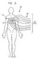
- Figure 6is an illustration which shows a patient fitted with a multi-connector Intelligent ECG System array.
- FIGS 7, 8, and 9are schematic diagrams of the circuitry employed by the present invention.
- FIG 1depicts a patient 10 who is being monitored by a conventional electrocardiograph instrument. Electrodes 12 borne by bands or pads are attached to the patient's skin. These electrodes 12 are coupled to a set of leads 14 which provide input signals to an ECG instrument 16 that generates cardiovascular waveforms on display 18. Conventional ECG electrode hardware is portrayed in Figure 2.
- a typical previous electrode 19 as shown in Figures 2(a) and 2(b)includes a terminal side "T” and a contact side labeled "C”.
- the electrode 19has outer and central portions 20 and 22 and a terminal 24 which receives a spring clip 26 that is connected to a lead 27.
- FIG. 2(b)The obverse or contact side C of the same electrode 19 is portrayed in Figure 2(b), which reveals an outer portion 20, an inner portion 28 and a central conductive portion 30.
- a snap connector 31may be used in place of the spring clip 26.
- Figure 2(c)is a side view of this conventional snap connector 31 that includes an outer portion 32 and a lead 33.
- Figure 2(d)is a bottom view that illustrates outer portion 32, and a conductive portion 34 that forms a recess 36 in the center of snap connector 31.
- FIG 3is a schematic perspective view of the electrode 38 employed by the preferred embodiment of the Intelligent ECG System.
- An electrode 40 having a contact side 40a and a connector side 40bis coupled to a snap connector 42 that includes a light-emitting diode (LED) 44 and a lead 45.
- Figure 4is a perspective schematic depiction of the Intelligent ECG System comprising several electrodes 38 with LEDs 44 linked by leads 45 to an ECG instrument 46 that includes a display 47.
- LEDlight-emitting diode
- FIG. 5is a schematic, cross-sectional view of the electrode 38 pictured in Figure 3.
- an LED 44in anchored in the top central portion of snap connector 42. Wires from the LED 44 run into lead 45 that extend to ECG instrument 46 (not shown in Figure 5).
- An adhesive 48 attached to pad 40provides a means of securing the present invention to a patient.
- the electrode 38comprises a metal post 50 embedded in the center of pad 40. The post 50 protrudes up from the insulative pad 40 through connector side 40b, which is the side opposite the side that touches the patient's skin.
- the post 50has an upper rounded portion 50a shaped like a flattened or oblate spheroid.
- a generally cylindrical shank or middle portion 50bextends downward from the rounded top 50a to a lower portion 50c that is shaped like a flange and is contained within the body of pad 40.
- a spring contact 52surrounds post 50 and provides an electrical coupling to one of the wires inside lead 46.
- the bottom portion 50c of the post 50extends through and past a lower central surface 54 of pad 40 that is capable of holding a volume of conductive jelly 55.
- the lower central surface 54is shaped like a concave surface to promote the adhesion of the jelly to the electrode.
- the jelly 55is commonly used to enhance the electrical continuity between electrodes and the epidermis.
- FIG. 6is an illustration which shows a patient fitted with a multi-connector Intelligent ECG System array 56.
- the arrayincludes a multi-connector ECG pad 57 which has a number of individual connection sites 58 that are each coupled to a set of leads 60.
- An alternative embodiment of the multi-lead arraymay employ a number of electrodes 38 and leads 60 without pad 57.
- FIG. 7is a diagram that includes the sensor circuitry employed by the present invention.
- Electrode 38which includes snap connector 42, LED 44, metal post 50, and spring contact 52, is shown with detector circuitry 49 in this schematic representation.
- Line 45aconnects spring clip 52 to node 61, which is also connected to a current source 62 and node 63.
- An amplifier 63 and display 64extend in series from node 63, which is also linked to the positive terminal 69 of a comparator 68.
- a reference voltage Vris applied to the comparator's negative terminal 70.
- the output of the comparator 68flows through a resistor 72 that is coupled to node 73, which is also connected to lead 45c from LED 44 and an alternate LED driver 74.
- the second lead 45b from the LED 44is grounded at ground terminal 76.
- the detector 49comprises the current source 62, comparator 68, and resistor 72 in the arrangement shown in Figure 7.
- wire 45aconducts the ECG signal from metal post 50 to amplifier 64.
- the amplified signalis then presented as a waveform on display 66.
- the electrode impedancebecomes relatively high compared to its nominal value while there is good electrical continuity between the electrode and the patient's skin.
- the small flow of current from source 62causes the voltage at lead 45a (node 61) to rise above reference voltage Vr, which is applied at negative input terminal 70 of comparator 68.
- This changecauses the output of the comparator 68 to rise to a positive voltage which is capable of turning on LED 44.
- Resistor 72which lies in series between comparator 68 and LED 44, serves to limit the current which can flow back to the LED 44 through leads 45b and 45c.
- Lead 45cwhich is coupled to ground terminal 76, can also be conveniently employed as a shield for the leads that convey the ECG signal from electrode 38.
- the LED 44can also be driven by another signal such as a lead sequencer 74. If the multi-electrode embodiment shown in Figure 6 is employed, the LEDs 44 can be illuminated sequentially to guide a technician to attach each electrode to the patient in the proper order and in the appropriate location. This operation can be accomplished using a driver 74 that contains a microprocessor 78 which is capable of storing a program in a memory 80 and then executing the stored program to help a technician perform a complex ECG procedure.
- the processorcan also be configured to provide instructions for the user on display 66.
- Figure 8presents an alternative circuit which may be employed to practice the present invention. Unlike the DC current source 62 provided in the hardware shown in Figure 7, the configuration illustrated by Figure 8 utilizes a voltage to current converter 82 and an AC voltage source 83.
- the voltage to current converter 82may employ a single resistor or a single capacitor.
- Lead 45 from electrode 38is connected to converter 82 at node 84, and both are coupled to ECG amplifier 64, display 66, and AC voltage amplifier 88 at node 86.
- An AC voltage source 83is coupled to converter 82 at node 81.
- An AC voltage amplifier 88feeds a signal to a synchronous AC detector 85, which, in turn, provides an output to comparator 68.
- the synchronous AC detector 85is selected to provide a high signal-to-noise ration.
- a tuned detectormay be substituted for the synchronous detector 85.
- LED 44draws current from comparator 68 through resistor 72.
- the hardware depicted in Figure 8may also include an alternate LED driver 74, a processor 78, and a memory 80 connected in series from node 87.
- the AC converter 82 and AC voltage source 83may be beneficially employed when the frequency chosen for the system is outside of the passband of the ECG amplifier 64.
- the electrode to skin impedanceis then measured by sensing the AC voltage on lead 45, which is accomplished by placing an AC amplifier 88 and detector 85 in series between node 86 and comparator 68.
- One advantage that is gained by using a low radio-frequency AC signal of about 50 kHzis that the present invention is then also capable of measuring the impedance between two electrodes 38 as it changes slightly with the patient's respiration rate.
- An alternative embodiment of the inventionmay utilize a sensor circuit which measures a change in capacitance between the patient 10 and the electrode 38 to determine when such a failure has occurred.
- FIG 9is a schematic depiction of circuitry which may be used to practice the present invention. Comparator 68 may not necessary be employed to drive LED 44 directly, although such an arrangement would suffice and may lead to significant cost savings for the manufacturer. In another configuration, a large number of leads 45 may be coupled to current sources and comparators 90 and LED drivers 92 with a microprocessor 78 and a display 66 as shown in Figure 9. When this circuitry senses a voltage level that is associated with a poorly attached electrode 38, processor 78 acts to turn on the LED 44 affixed to that deficiently attached electrode 38.
- the hardware shown in Figure 9could also be used to illuminate a number of LEDs 44 in a particular sequence to guide a technician through the task of placing a group of electrodes 38 in their proper locations on a patient.
- the comparatorsmay be employed to signal that an adequate electrical contact has been established between the electrode and the subject's skin.
- the processor 78could be programmed to feed textual or diagrammatic instructions to display 66 to guide a technician as the LEDs on each electrode are activated in a predetermined order.
Landscapes
- Health & Medical Sciences (AREA)
- Life Sciences & Earth Sciences (AREA)
- Medical Informatics (AREA)
- Biophysics (AREA)
- Pathology (AREA)
- Engineering & Computer Science (AREA)
- Biomedical Technology (AREA)
- Heart & Thoracic Surgery (AREA)
- Physics & Mathematics (AREA)
- Molecular Biology (AREA)
- Surgery (AREA)
- Animal Behavior & Ethology (AREA)
- General Health & Medical Sciences (AREA)
- Public Health (AREA)
- Veterinary Medicine (AREA)
- Cardiology (AREA)
- Measurement And Recording Of Electrical Phenomena And Electrical Characteristics Of The Living Body (AREA)
Description
- The present invention is an apparatus that provides an electrocardiographic system that detects faulty electrode attachments and guides a technician to insure that leads to the patient are connected in the proper order and in the correct position on the patient's skin.
- An electrocardiogram (ECG) is a printed graph of the waveform generated by the cyclical activation of the Heart. The ECG is a measurement of potential difference that requires at least two electrodes to be placed on a patient's skin. Conventional systems employ adhesive discs or pads having a conductive inner section that is applied directly to the patient's chest. This adhesive section is coupled to a terminal on the opposite side of the disc that faces away from the skin. A wire lead is clipped to this terminal which conveys the electrical signal to the ECG instrument.
- The quality of the ECG measurement depends almost entirely upon a good connection between the patient's skin and the adhesive pad. Since ECG tests are often performed while the patient is on a moving treadmill to induce increased heart and respiratory rates, one common problem encountered by technicians performing this medical examination is an inadequate connection between the pads and the skin. This problem is especially troublesome during complex procedures involving the application of many adhesive discs. Recent advances in cardiac medicine have enabled physicians to make more accurate diagnoses of serious heart conditions. These advanced techniques involve ECG tests that require the placement of fifty or more electrodes on the person being tested. One pad among fifty that is poorly coupled to the epidermis can be difficult to isolate and may even ruin one of these complex examinations.
- US-Patent 4,577,639 discloses an apparatus and a method for automatic lead selection in electrocardiography which can determine simultaneously the condition of all electrodes in an ECG monitoring configuration. Leads from electrodes placed on a patient are coupled to a lead fail detector means for detecting when one or more leads are disconnected or improperly connected. Signals and information resulting from the processing of received signals from the electrodes are displayed on a display. In case a failed lead is detected visual indicators are displayed on the display wherein the visual indicators indicate which leads have failed.
- US-Patent 4,141,351 discloses an ECG electrode impedance checking system for emergency medical service which comprises a circuit for checking a plurality of impedances having a common connection point, where the impedance of each ECG electrode contact is automatically and sequentially checked during the initial calibration transmission. A plurality of electrodes have been coupled to a patient and signals from these electrodes are transmitted to a monitoring equipment. This monitoring equipment includes the circuitry for monitoring impedances of the electrodes attached to the patient. The monitoring equipment includes a visual indicator such as a LED display. During the electrode checking period, the electrode impedances are checked sequentially and any high resistance or open circuit will be indicated by the illumination of the corresponding LED.
- US-Patent 3,750,094 relates to electrodes for electro-cardiographs and more particularly to an electrode and releasable connector combination usable within electro-cardiographs. The connector-electrode assembly consists of an electrode having a releasable connector connected thereto with a lead adapted to transmit signals to an associated electro-cardiograph.
- The problem of providing a highly reliable ECG device has presented a major challenge to designers in the health care field. The development of a straightforward method of insuring good electrical connections to the patient during an ECG examination would represent a major technological advance in the instrumentation business. The enhanced peformance which could be achieved using such an innovative device would satisfy a long felt need within the medical profession.
- The Intelligent Electrocardiogram System is a method and apparatus that solves the problem of faulty electrical connections between a patient and an ECG instrument. The present invention senses a faulty or inadequate electrical coupling between the ECG electrode and the patient's skin. When a change in the impedance between the conductive portion of the electrode and the patient is detected, a visual warning is issued by a light emitting diode (LED) affixed on the electrode. This signal informs the technician performing the ECG examination to correct the failed coupling to the patient. The LED may be accompanied by an audible warning. The Intelligent Electrocardiogram System may also be used in conjunction with an electrocardiogram instrument that includes a microprocessor and memory to guide a technician to connect the many leads on the patient to the instrument in the proper sequence and to the proper locations.
- An appreciation of other aims and objectives of the present invention and a more complete and comprehensive understanding of this invention may be achieved by studying the following description of a preferred embodiment and by referring to the accompanying drawings.
- Figure 1 is a schematic representation of a patient connected to a conventional electrocardiograph instrument.
- Figures 2(a, b, c, and d) are perspective views of conventional ECG electrode hardware.
- Figure 3 is a perspective view of the preferred embodiment of the electrode employed by the Intelligent ECG System.
- Figure 4 is a perspective schematic depiction of the Intelligent ECG System.
- Figure 5 is a schematic, cross-sectional view of the electrode pictured in Figure 3.
- Figure 6 is an illustration which shows a patient fitted with a multi-connector Intelligent ECG System array.
- Figures 7, 8, and 9 are schematic diagrams of the circuitry employed by the present invention.
- Figure 1 depicts a
patient 10 who is being monitored by a conventional electrocardiograph instrument.Electrodes 12 borne by bands or pads are attached to the patient's skin. Theseelectrodes 12 are coupled to a set ofleads 14 which provide input signals to anECG instrument 16 that generates cardiovascular waveforms ondisplay 18. Conventional ECG electrode hardware is portrayed in Figure 2. A typicalprevious electrode 19 as shown in Figures 2(a) and 2(b) includes a terminal side "T" and a contact side labeled "C". Theelectrode 19 has outer andcentral portions terminal 24 which receives aspring clip 26 that is connected to alead 27. The obverse or contact side C of thesame electrode 19 is portrayed in Figure 2(b), which reveals anouter portion 20, aninner portion 28 and a centralconductive portion 30. Asnap connector 31 may be used in place of thespring clip 26. Figure 2(c) is a side view of thisconventional snap connector 31 that includes anouter portion 32 and alead 33. Figure 2(d) is a bottom view that illustratesouter portion 32, and aconductive portion 34 that forms arecess 36 in the center ofsnap connector 31. - Figure 3 is a schematic perspective view of the
electrode 38 employed by the preferred embodiment of the Intelligent ECG System. Anelectrode 40 having a contact side 40a and aconnector side 40b is coupled to asnap connector 42 that includes a light-emitting diode (LED) 44 and alead 45. Figure 4 is a perspective schematic depiction of the Intelligent ECG System comprisingseveral electrodes 38 withLEDs 44 linked byleads 45 to anECG instrument 46 that includes adisplay 47. - Figure 5 is a schematic, cross-sectional view of the
electrode 38 pictured in Figure 3. In the preferred embodiment of the invention, anLED 44 in anchored in the top central portion ofsnap connector 42. Wires from theLED 44 run intolead 45 that extend to ECG instrument 46 (not shown in Figure 5). An adhesive 48 attached topad 40 provides a means of securing the present invention to a patient. Theelectrode 38 comprises ametal post 50 embedded in the center ofpad 40. Thepost 50 protrudes up from theinsulative pad 40 throughconnector side 40b, which is the side opposite the side that touches the patient's skin. Thepost 50 has an upperrounded portion 50a shaped like a flattened or oblate spheroid. A generally cylindrical shank ormiddle portion 50b extends downward from therounded top 50a to a lower portion 50c that is shaped like a flange and is contained within the body ofpad 40. Aspring contact 52 surroundspost 50 and provides an electrical coupling to one of the wires insidelead 46. The bottom portion 50c of thepost 50 extends through and past a lowercentral surface 54 ofpad 40 that is capable of holding a volume ofconductive jelly 55. In the preferred embodiment of the present invention, the lowercentral surface 54 is shaped like a concave surface to promote the adhesion of the jelly to the electrode. Thejelly 55 is commonly used to enhance the electrical continuity between electrodes and the epidermis. - Figure 6 is an illustration which shows a patient fitted with a multi-connector Intelligent
ECG System array 56. The array includes amulti-connector ECG pad 57 which has a number ofindividual connection sites 58 that are each coupled to a set of leads 60. An alternative embodiment of the multi-lead array may employ a number ofelectrodes 38 and leads 60 withoutpad 57. - Figure 7 is a diagram that includes the sensor circuitry employed by the present invention.
Electrode 38, which includessnap connector 42,LED 44,metal post 50, andspring contact 52, is shown withdetector circuitry 49 in this schematic representation.Line 45a connectsspring clip 52 tonode 61, which is also connected to acurrent source 62 andnode 63. Anamplifier 63 anddisplay 64 extend in series fromnode 63, which is also linked to thepositive terminal 69 of acomparator 68. A reference voltage Vr is applied to the comparator'snegative terminal 70. The output of thecomparator 68 flows through aresistor 72 that is coupled tonode 73, which is also connected to lead 45c fromLED 44 and analternate LED driver 74. Thesecond lead 45b from theLED 44 is grounded atground terminal 76. In the preferred embodiment, thedetector 49 comprises thecurrent source 62,comparator 68, andresistor 72 in the arrangement shown in Figure 7. - When the
electrode 38 is attached to a patient,wire 45a conducts the ECG signal frommetal post 50 toamplifier 64. The amplified signal is then presented as a waveform ondisplay 66. When the coupling between theelectrode 38 and the patient is faulty or inadequate, the electrode impedance becomes relatively high compared to its nominal value while there is good electrical continuity between the electrode and the patient's skin. When this impedance rises, the small flow of current fromsource 62 causes the voltage atlead 45a (node 61) to rise above reference voltage Vr, which is applied atnegative input terminal 70 ofcomparator 68. This change, in turn, causes the output of thecomparator 68 to rise to a positive voltage which is capable of turning onLED 44.Resistor 72, which lies in series betweencomparator 68 andLED 44, serves to limit the current which can flow back to theLED 44 throughleads 45b and 45c. Lead 45c, which is coupled toground terminal 76, can also be conveniently employed as a shield for the leads that convey the ECG signal fromelectrode 38. - The
LED 44 can also be driven by another signal such as alead sequencer 74. If the multi-electrode embodiment shown in Figure 6 is employed, theLEDs 44 can be illuminated sequentially to guide a technician to attach each electrode to the patient in the proper order and in the appropriate location. This operation can be accomplished using adriver 74 that contains amicroprocessor 78 which is capable of storing a program in amemory 80 and then executing the stored program to help a technician perform a complex ECG procedure. The processor can also be configured to provide instructions for the user ondisplay 66. - Figure 8 presents an alternative circuit which may be employed to practice the present invention. Unlike the DC
current source 62 provided in the hardware shown in Figure 7, the configuration illustrated by Figure 8 utilizes a voltage tocurrent converter 82 and anAC voltage source 83. The voltage tocurrent converter 82 may employ a single resistor or a single capacitor. Lead 45 fromelectrode 38 is connected toconverter 82 atnode 84, and both are coupled toECG amplifier 64,display 66, andAC voltage amplifier 88 atnode 86. AnAC voltage source 83 is coupled toconverter 82 atnode 81. AnAC voltage amplifier 88 feeds a signal to asynchronous AC detector 85, which, in turn, provides an output tocomparator 68. Thesynchronous AC detector 85 is selected to provide a high signal-to-noise ration. In an alternative embodiment, a tuned detector may be substituted for thesynchronous detector 85. Just as in Figure 7,LED 44 draws current fromcomparator 68 throughresistor 72. The hardware depicted in Figure 8 may also include analternate LED driver 74, aprocessor 78, and amemory 80 connected in series fromnode 87. - The
AC converter 82 andAC voltage source 83 may be beneficially employed when the frequency chosen for the system is outside of the passband of theECG amplifier 64. The electrode to skin impedance is then measured by sensing the AC voltage onlead 45, which is accomplished by placing anAC amplifier 88 anddetector 85 in series betweennode 86 andcomparator 68. One advantage that is gained by using a low radio-frequency AC signal of about 50 kHz is that the present invention is then also capable of measuring the impedance between twoelectrodes 38 as it changes slightly with the patient's respiration rate. - An alternative embodiment of the invention may utilize a sensor circuit which measures a change in capacitance between the patient 10 and the
electrode 38 to determine when such a failure has occurred. - Figure 9 is a schematic depiction of circuitry which may be used to practice the present invention.
Comparator 68 may not necessary be employed to driveLED 44 directly, although such an arrangement would suffice and may lead to significant cost savings for the manufacturer. In another configuration, a large number ofleads 45 may be coupled to current sources andcomparators 90 andLED drivers 92 with amicroprocessor 78 and adisplay 66 as shown in Figure 9. When this circuitry senses a voltage level that is associated with a poorly attachedelectrode 38,processor 78 acts to turn on theLED 44 affixed to that deficiently attachedelectrode 38. The hardware shown in Figure 9 could also be used to illuminate a number ofLEDs 44 in a particular sequence to guide a technician through the task of placing a group ofelectrodes 38 in their proper locations on a patient. In this case, the comparators may be employed to signal that an adequate electrical contact has been established between the electrode and the subject's skin. Simultaneously, theprocessor 78 could be programmed to feed textual or diagrammatic instructions to display 66 to guide a technician as the LEDs on each electrode are activated in a predetermined order. - Figure 1
- 10
- Patient
- 12
- Connections to patient's skin
- 14
- Leads
- 16
- Electrocardiogram instrument
- 18
- Display
- Figure 2
- 19
- Conventional electrode
- T
- Terminal side
- C
- Contact side
- 20
- Outer portion
- 22
- Central portion
- 24
- Terminal
- 26
- Spring clip
- 27
- Lead
- 28
- Inner portion of contact side of electrode
- 30
- Central conductive portion of contact side of electrode
- 31
- Snap connector
- 32
- Outer portion of snap connector
- 34
- Conductive portion of snap connector
- 36
- Recess in center of snap connector
- Figures 3 & 4
- 38
- Intelligent ECG System connector
- 40
- Electrode
- 40a
- Contact side of electrode
- 40b
- Connector side of electrode
- 42
- Electrode snap connector
- 44
- LED
- 45
- Lead
- 46
- ECG Instrument
- 47
- Display
- Figure 5
- 48
- Adhesive
- 49
- Detector circuit
- 50
- Metal post
- 50a
- Upper portion
- 50b
- Middle portion
- 50c
- Lower portion
- 52
- Spring contact fitted around post
- 54
- Lower central conductive surface of pad
- 55
- Conductive jelly
- Figure 6
- 56
- Multi-connector Intelligent ECG System Array
- 57
- Multi-connector Intelligent ECG System Array pad
- 58
- Individual connection site
- 60
- Multiple leads to ECG instrument
- Figure 7
- 61
- Node
- 62
- DC current source
- 63
- Node
- 64
- Amplifier
- 66
- Display
- 68
- Comparator
- 69
- Positive input terminal of comparator
- 70
- Negative input terminal of comparator
- 72
- Current limiting resistor
- 73
- Node
- 74
- Alternate LED driver
- 76
- Ground
- 78
- Processor
- 80
- Memory
- Figure 8
- 81
- Node
- 82
- Voltage to current converter
- 83
- AC voltage source
- 84
- Node
- 85
- Synchronous AC detector
- 86
- Node
- 87
- Node
- 88
- AC amplifier
- Figure 9
- 90
- Current sources and comparators
- 92
- LED drivers
Claims (8)
- An apparatus for automatically detecting a failure of a connection placed on a patient (10) by activating an alarm on said patient where said failure occurs comprising:
a conductive means (50,54,55) for making an electrical connection to said patient (10);
a coupling means (42) for making an electrical connection to said conductive means (50,54,55), said coupling means (42) having an end portion attached to said conductive means;
a detector means (49) coupled to said conductive means (50,54,55) for sensing when said conductive means (50,54,55) becomes partially detached from said patient (10); and
a visual alarm means (44) for indicating a failure when said detector means (49) senses an inadequate connection between said conductive means (50,54,55) and said patient (10),
characterized in that
said visual alarm means (44) is affixed to said end portion of said coupling means (42), and
said visual alarm means (44) is located next to said conductive means (50,54,55) to precisely indicate the position of said failure. - An apparatus as claimed in claim 1, further comprising
an insulative pad means (40) for making an insulating connection to said conductive means (50,54,55), said insulative pad means (40) having a lower central surface (54), said insulative pad means (40) also having an adhesion means (48) coupled to said conductive means (50,54,55) for maintaining said conductive means (50,54,55) in contact with said patient (10). - An apparatus as claimed in claim 2, in which said conductive means (50,54,55) comprises:
a generally cylindrical metal post (50) which protrudes up from said insulative pad means (40) from said lower central surface (54) of said pad means (40), said metal post (50) including:
an upper, generally oblate spheroid portion (50a),
a middle shank portion (50b), and
a lower flange portion (50c); and
a volume of conductive jelly (55) held by contact with said lower central surface (54) of said pad means (40), said lower flange portion (50c) of said post (50) extending into said volume of conductive jelly (55). - An apparatus as claimed in claim 1, in which said detector means (49) measures a change in resistance between said conductive means (50,54,55) and said patient (10).
- An apparatus as claimed in claim 1, in which said visual alarm means (44) is a light.
- An apparatus as claimed in claim 1, in which said visual alarm means (44) is a LED.
- An apparatus as claimed in claim 1, wherein said conductive means (50, 54, 55) comprises
an insulative pad (40) having a contact side (40a) and a connector side (40b);
a generally cylindrical metal terminal (50) having an upper portion (50a), a middle portion (50b), and a lower portion (50c), said upper portion (50a) protruding from said connector side (40), said terminal (50) extending through said pad (40) to said contact side (40a) of said pad (40);
a volume of conductive jelly (55) in contact with said lower portion (50c) of said terminal (50);
a spring contact (52) located around said middle portion (50b) of said metal terminal (50);
a lead (45) connected to said spring contact (52); and
an adhesive (48) located on said contact side (40a) of said pad (40) for maintaining attachment to a patient (10);
wherein said detector means (49) measures a change in electrical impedance between said metal terminal (50) and said patient (10), said detector means (49) including a DC current source (62), a comparator (68) and a current limiting resistor (72), said current source (62) being connected to said terminal (50), said comparator (68) being connected to said current source (62), said resistor (72) being connected to said comparator (68);
wherein said visual alarm means comprises a lamp (44) which illuminates when said detector means (49) senses said change in electrical impedance, said lamp (44) being connected to said comparator (68) through said resistor (72); and
wherein said apparatus further comprises an ECG amplifier (64) coupled to said lead (45), and an ECG display (66) coupled to said amplifier (64). - An apparatus as claimed in claim 1, wherein said conductive means further comprises
an insulative pad (40) having a contact side (40a) and a connector side (40b);
a generally cylindrical metal terminal (50) having an upper portion (50a), a middle portion (50b), and a lower portion (50c), said upper portion (50a) protruding from said connector side (40b), said terminal (50) extending through said pad (40) to said contact side (40a) of said pad (40);
a volume of conductive jelly (55) in contact with said lower portion (55c) of said terminal (50);
a spring contact (52) located around said middle portion (50b) of said metal terminal (50);
a lead (45) connected to said spring contact (52); and
an adhesive (48) located on said contact side (40a) of said pad (40) for maintaining attachment to a patient (10);
wherein said detector means (49) comprises an AC sensor circuit (82,83,88,85,68,72) that measures a change in electrical impedance between said metal terminal (50) and said patient (10), said AC sensor circuit (82,83,88,85, 68,72) including
a voltage to current converter (82),
an AC voltage source (83),
a synchronous AC detector (85),
an AC voltage amplifier (88),
a comparator (68), and
a current limiting resistor (72);
said converter (82) being connected to said terminal (50), said AC voltage source (83) being connected between said converter (82) and said synchronous AC detector (85), said AC voltage amplifier (88) being connected between said converter (82) and said synchronous AC detector (85), said comparator (68) being connected to said synchronous AC detector (85), said resistor (72) being connected to said comparator (68);
wherein said visual alarm means comprises a lamp (44) which illuminates when said AC sensor circuit (82,83,88,85,68,72) senses said change in electrical impedance, said lamp (44) being connected to said comparator (68) through said resistor (72); and
wherein said apparatus further comprises an ECG amplifier (64) coupled to said lead, and an ECG display (66) coupled to said amplifier (64).
Applications Claiming Priority (2)
| Application Number | Priority Date | Filing Date | Title |
|---|---|---|---|
| US07/505,795US5042498A (en) | 1990-04-06 | 1990-04-06 | Intelligent electrocardiogram system |
| US505795 | 1990-04-06 |
Publications (2)
| Publication Number | Publication Date |
|---|---|
| EP0450350A1 EP0450350A1 (en) | 1991-10-09 |
| EP0450350B1true EP0450350B1 (en) | 1996-05-01 |
Family
ID=24011864
Family Applications (1)
| Application Number | Title | Priority Date | Filing Date |
|---|---|---|---|
| EP91103756AExpired - LifetimeEP0450350B1 (en) | 1990-04-06 | 1991-03-12 | Intelligent electrocardiogram |
Country Status (4)
| Country | Link |
|---|---|
| US (1) | US5042498A (en) |
| EP (1) | EP0450350B1 (en) |
| JP (1) | JPH04227229A (en) |
| DE (1) | DE69119133T2 (en) |
Families Citing this family (52)
| Publication number | Priority date | Publication date | Assignee | Title |
|---|---|---|---|---|
| US5415164A (en)* | 1991-11-04 | 1995-05-16 | Biofield Corp. | Apparatus and method for screening and diagnosing trauma or disease in body tissues |
| US5261402A (en)* | 1992-07-20 | 1993-11-16 | Graphic Controls Corporation | Snapless, tabless, disposable medical electrode with low profile |
| DE4329898A1 (en) | 1993-09-04 | 1995-04-06 | Marcus Dr Besson | Wireless medical diagnostic and monitoring device |
| JP3561858B2 (en)* | 1995-12-28 | 2004-09-02 | 務 大竹 | Medical device with medical electrode body |
| US5782761A (en)* | 1996-01-24 | 1998-07-21 | Graphic Controls Corporation | Molded electrode |
| JPH1156802A (en)* | 1997-08-27 | 1999-03-02 | Nec Corp | Medical electrode and medical device |
| US6217525B1 (en) | 1998-04-30 | 2001-04-17 | Medtronic Physio-Control Manufacturing Corp. | Reduced lead set device and method for detecting acute cardiac ischemic conditions |
| US6205355B1 (en) | 1999-02-16 | 2001-03-20 | Marisa Lomanto | Electrocardiograph leadwire assembly |
| TW436276B (en)* | 1999-06-30 | 2001-05-28 | Ind Tech Res Inst | Device for detecting leads-off condition in a multi-electrode medical diagnosis system and method thereof |
| WO2001054578A1 (en)* | 2000-01-31 | 2001-08-02 | Pearlman Justin D | Multivariate cardiac monitor |
| US7572231B2 (en)* | 2000-01-31 | 2009-08-11 | Pearlman Justin D | Method of and system for signal separation during multivariate physiological monitoring |
| US6441747B1 (en) | 2000-04-18 | 2002-08-27 | Motorola, Inc. | Wireless system protocol for telemetry monitoring |
| US6496705B1 (en) | 2000-04-18 | 2002-12-17 | Motorola Inc. | Programmable wireless electrode system for medical monitoring |
| EP1303213A4 (en) | 2000-07-18 | 2008-04-02 | Motorola Inc | Wireless electrocardiograph system and method |
| EP1811296A1 (en)* | 2000-08-23 | 2007-07-25 | Shiseido Company, Limited | Methods and apparatus for measuring skin surface condition |
| US6807439B2 (en)* | 2001-04-03 | 2004-10-19 | Medtronic, Inc. | System and method for detecting dislodgement of an implantable medical device |
| US7933642B2 (en) | 2001-07-17 | 2011-04-26 | Rud Istvan | Wireless ECG system |
| US7197357B2 (en) | 2001-07-17 | 2007-03-27 | Life Sync Corporation | Wireless ECG system |
| EP1321164A1 (en)* | 2001-12-21 | 2003-06-25 | Ultra Scientific Instruments Limited | Indicator light |
| DE60309559T2 (en)* | 2003-01-09 | 2007-08-23 | Ge Healthcare Finland Oy | Shielding arrangement for ECG connection wires |
| WO2004075738A2 (en)* | 2003-02-26 | 2004-09-10 | Compumedics Usa, Inc. | Method and apparatus for continuous electrode impedance monitoring |
| US8068905B2 (en)* | 2004-02-26 | 2011-11-29 | Compumedics Limited | Method and apparatus for continuous electrode impedance monitoring |
| US20060004295A1 (en)* | 2004-06-29 | 2006-01-05 | Randolph Prydekker | Electrode connectivity determination system |
| US20060084855A1 (en)* | 2004-10-20 | 2006-04-20 | Drager Medical Ag & Co. Kgaa | Electrode belt for carrying out electrodiagnostic procedures on the human body |
| DE102005012088A1 (en)* | 2005-03-16 | 2006-09-21 | Viasys Healthcare Gmbh | Electrode, measuring line and measuring method |
| US8150489B2 (en)* | 2005-04-19 | 2012-04-03 | Koninklijke Philips Electronics N.V. | System and method for measuring bioelectrical signals of a user |
| DE102005021581A1 (en)* | 2005-05-10 | 2006-11-23 | Universitätsklinikum Freiburg | Holder module for a device implanted in a human body for detecting and or stimulating heart rhythm events |
| JP4867364B2 (en)* | 2006-01-27 | 2012-02-01 | 横浜ゴム株式会社 | Bioelectric information measuring device |
| CA2716783A1 (en) | 2008-02-25 | 2009-09-03 | Ziehm Medical Llc | Apparatus for measuring, recording and transmitting electrocardiogram measurements |
| DE102008049287A1 (en) | 2008-09-26 | 2010-04-01 | Cardinal Health Germany 234 Gmbh | ECG system and procedures |
| CA2760369C (en)* | 2009-05-01 | 2016-12-20 | Compumedics Limited | Integrated electrode connector and impedance indicator |
| CN102686152A (en)* | 2009-10-16 | 2012-09-19 | 飞机医疗有限公司 | Transducer mountings and wearable monitors |
| EP2446865A1 (en)* | 2010-10-28 | 2012-05-02 | Louise Mohn | Thermostimulation apparatus |
| CN102175920B (en)* | 2011-03-09 | 2013-05-15 | 史建军 | Medical electrode plate quality identification and display device and method thereof |
| JP5907677B2 (en)* | 2011-07-19 | 2016-04-26 | フクダ電子株式会社 | Bioelectrode cover and electrostatic induction noise suppression method |
| US9180288B2 (en) | 2011-09-01 | 2015-11-10 | Zoll Medical Corporation | Medical equipment electrodes |
| JP5860267B2 (en)* | 2011-11-01 | 2016-02-16 | 株式会社モリタ製作所 | Dental treatment device |
| US20150250554A1 (en)* | 2014-03-05 | 2015-09-10 | General Electric Company | Luminescent patient connector for physiologic signal acquisition |
| EP3164064A1 (en) | 2014-07-03 | 2017-05-10 | Koninklijke Philips N.V. | Medical electrode |
| US20170347910A1 (en)* | 2015-01-14 | 2017-12-07 | Rs Medical Monitoring Ltd. | A method and system for monitoring internal electrical impedance of a biological object |
| TWM514331U (en)* | 2015-07-08 | 2015-12-21 | U Gym Technology Corp | Electrotherapy wire structure |
| US10660572B2 (en)* | 2015-11-14 | 2020-05-26 | Zeto, Inc. | System and method for testing contact quality of electrical-biosignal electrodes |
| US10799180B2 (en)* | 2015-11-14 | 2020-10-13 | Zeto, Inc. | System and method for testing contact quality of electrical-biosignal electrodes |
| US10210721B2 (en) | 2016-12-09 | 2019-02-19 | General Electric Company | Active ECG lead quality indication at the point of care |
| US11241297B2 (en) | 2016-12-12 | 2022-02-08 | Cadwell Laboratories, Inc. | System and method for high density electrode management |
| US20180221646A1 (en)* | 2017-02-09 | 2018-08-09 | Jennifer Silverton | Wireless Electrodes |
| EP3703523B1 (en) | 2017-12-01 | 2024-02-07 | Zeto, Inc. | Headset and electrodes for sensing bioelectrical potential and methods of operation thereof |
| EP3527128A1 (en)* | 2018-02-20 | 2019-08-21 | Koninklijke Philips N.V. | Ecg electrode connector and ecg cable |
| EP3888191A4 (en)* | 2018-11-30 | 2022-10-05 | Cadwell Laboratories, Inc. | System and method for high density electrode management |
| US11744504B2 (en) | 2021-08-05 | 2023-09-05 | Zeto, Inc. | Flexible electroencephalography headset |
| US20240108903A1 (en)* | 2022-09-30 | 2024-04-04 | Zoll Medical Corporation | Wearable cardioverter defibrillator component assembly verification |
| DE102023114148A1 (en)* | 2023-05-30 | 2024-12-05 | AdjuCor GmbH | CARDIAC ASSISTANCE DEVICE WITH AN EXPANDABLE UNIT |
Family Cites Families (11)
| Publication number | Priority date | Publication date | Assignee | Title |
|---|---|---|---|---|
| US3495584A (en)* | 1965-06-03 | 1970-02-17 | Gen Electric | Lead failure detection circuit for a cardiac monitor |
| US3602215A (en)* | 1968-09-16 | 1971-08-31 | Honeywell Inc | Electrode failure detection device |
| US3757778A (en)* | 1971-01-13 | 1973-09-11 | Comprehensive Health Testing L | Electrocardiograph lead distribution and contact testing apparatus |
| US3834373A (en)* | 1972-02-24 | 1974-09-10 | T Sato | Silver, silver chloride electrodes |
| US3750094A (en)* | 1972-03-09 | 1973-07-31 | Zenco Engineering Corp | Electrical connector |
| GB2005142B (en)* | 1977-09-08 | 1982-02-10 | Tdk Electronics Co Ltd | Electrodes for living bodies |
| US4141351A (en)* | 1977-09-12 | 1979-02-27 | Motorola, Inc. | ECG electrode impedance checking system as for emergency medical service |
| US4235242A (en)* | 1979-04-02 | 1980-11-25 | Med General, Inc. | Electronic circuit permitting simultaneous use of stimulating and monitoring equipment |
| EP0091899A1 (en)* | 1981-10-22 | 1983-10-26 | HÖÖG, Anders | Heart activity indicator |
| DE3246473A1 (en)* | 1982-12-15 | 1984-06-20 | Siemens AG, 1000 Berlin und 8000 München | CIRCUIT ARRANGEMENT FOR DETECTING AN ELECTRICAL LINE INTERRUPT |
| US4577639A (en)* | 1984-11-08 | 1986-03-25 | Spacelabs, Inc. | Apparatus and method for automatic lead selection in electrocardiography |
- 1990
- 1990-04-06USUS07/505,795patent/US5042498A/ennot_activeExpired - Fee Related
- 1991
- 1991-03-12DEDE69119133Tpatent/DE69119133T2/ennot_activeExpired - Fee Related
- 1991-03-12EPEP91103756Apatent/EP0450350B1/ennot_activeExpired - Lifetime
- 1991-04-03JPJP3098042Apatent/JPH04227229A/enactivePending
Also Published As
| Publication number | Publication date |
|---|---|
| DE69119133T2 (en) | 1996-12-12 |
| JPH04227229A (en) | 1992-08-17 |
| EP0450350A1 (en) | 1991-10-09 |
| US5042498A (en) | 1991-08-27 |
| DE69119133D1 (en) | 1996-06-05 |
Similar Documents
| Publication | Publication Date | Title |
|---|---|---|
| EP0450350B1 (en) | Intelligent electrocardiogram | |
| CN101953685B (en) | Method and system to measure ecg and respiration | |
| US7917201B2 (en) | Method and apparatus for determining optimal neuromuscular detection sites, novel diagnostic biosensor array formed in accordance with the same, and novel method for testing a patient using the novel diagnostic biosensor array | |
| US4498479A (en) | Electrocardiograph (ECG) electrode testing system | |
| USRE37970E1 (en) | Pulse oximetry testing | |
| US6553246B1 (en) | Universal electrocardiogram sensor positioning device and method for four sizes including extra large | |
| US8233971B2 (en) | Automated identification of culprit coronary artery | |
| US4350164A (en) | Portable, life monitor, medical instrument | |
| MX2007012064A (en) | Cable monitoring apparatus. | |
| US10588529B2 (en) | ECG monitoring system and method | |
| US3633569A (en) | Arrhythmia counter | |
| US7758342B2 (en) | Detecting and indicating a proximity of a dental instrument to a tooth apical foramen | |
| EP0068032B1 (en) | Electrocardiograph | |
| KR20130134417A (en) | Apparatus sensing and detecting spots on the body suitable for acupuncture | |
| US3910258A (en) | Cerebral activity monitor | |
| JP2014503251A (en) | Automatic identification of occlusion position in the responsible coronary artery | |
| KR20000046465A (en) | Lead mutilation detecting method of biometer and device thereof | |
| CN115684994A (en) | Electrocardio lead wire, method and device for detecting electrocardio lead wire and medium | |
| CN112386260A (en) | Electrocardiogram monitoring device integrating BCG (BCG-Grating) signals | |
| CN1228290A (en) | newborn physiological parameter monitor | |
| EP3880065A2 (en) | Handheld ecg monitoring system with fault detection | |
| CN102970922B (en) | The Emergency pediatrics ECG with integrated instruction leads group | |
| JP6342532B2 (en) | Pulse group, skin resistance and respiratory measurement device | |
| CN110495873B (en) | Electrocardiogram detection device | |
| US20100261991A1 (en) | Apparatus for wire or wireless ECG machine with only two leads |
Legal Events
| Date | Code | Title | Description |
|---|---|---|---|
| PUAI | Public reference made under article 153(3) epc to a published international application that has entered the european phase | Free format text:ORIGINAL CODE: 0009012 | |
| AK | Designated contracting states | Kind code of ref document:A1 Designated state(s):DE FR GB | |
| 17P | Request for examination filed | Effective date:19920103 | |
| 17Q | First examination report despatched | Effective date:19941021 | |
| GRAA | (expected) grant | Free format text:ORIGINAL CODE: 0009210 | |
| AK | Designated contracting states | Kind code of ref document:B1 Designated state(s):DE FR GB | |
| REF | Corresponds to: | Ref document number:69119133 Country of ref document:DE Date of ref document:19960605 | |
| ET | Fr: translation filed | ||
| PLBE | No opposition filed within time limit | Free format text:ORIGINAL CODE: 0009261 | |
| STAA | Information on the status of an ep patent application or granted ep patent | Free format text:STATUS: NO OPPOSITION FILED WITHIN TIME LIMIT | |
| 26N | No opposition filed | ||
| PGFP | Annual fee paid to national office [announced via postgrant information from national office to epo] | Ref country code:FR Payment date:19980221 Year of fee payment:8 | |
| PGFP | Annual fee paid to national office [announced via postgrant information from national office to epo] | Ref country code:DE Payment date:19980223 Year of fee payment:8 | |
| PGFP | Annual fee paid to national office [announced via postgrant information from national office to epo] | Ref country code:GB Payment date:19980226 Year of fee payment:8 | |
| PG25 | Lapsed in a contracting state [announced via postgrant information from national office to epo] | Ref country code:GB Free format text:LAPSE BECAUSE OF NON-PAYMENT OF DUE FEES Effective date:19990312 | |
| GBPC | Gb: european patent ceased through non-payment of renewal fee | Effective date:19990312 | |
| PG25 | Lapsed in a contracting state [announced via postgrant information from national office to epo] | Ref country code:FR Free format text:LAPSE BECAUSE OF NON-PAYMENT OF DUE FEES Effective date:19991130 | |
| REG | Reference to a national code | Ref country code:FR Ref legal event code:ST | |
| PG25 | Lapsed in a contracting state [announced via postgrant information from national office to epo] | Ref country code:DE Free format text:LAPSE BECAUSE OF NON-PAYMENT OF DUE FEES Effective date:20000101 |