EP0447991B1 - Apparatus for measuring the distribution of the size of diffraction-scattering type particles - Google Patents
Apparatus for measuring the distribution of the size of diffraction-scattering type particlesDownload PDFInfo
- Publication number
- EP0447991B1 EP0447991B1EP19910104060EP91104060AEP0447991B1EP 0447991 B1EP0447991 B1EP 0447991B1EP 19910104060EP19910104060EP 19910104060EP 91104060 AEP91104060 AEP 91104060AEP 0447991 B1EP0447991 B1EP 0447991B1
- Authority
- EP
- European Patent Office
- Prior art keywords
- light
- sample
- cell
- sample cell
- scattered
- Prior art date
- Legal status (The legal status is an assumption and is not a legal conclusion. Google has not performed a legal analysis and makes no representation as to the accuracy of the status listed.)
- Expired - Lifetime
Links
Images


Classifications
- G—PHYSICS
- G01—MEASURING; TESTING
- G01N—INVESTIGATING OR ANALYSING MATERIALS BY DETERMINING THEIR CHEMICAL OR PHYSICAL PROPERTIES
- G01N15/00—Investigating characteristics of particles; Investigating permeability, pore-volume or surface-area of porous materials
- G01N15/02—Investigating particle size or size distribution
- G01N15/0205—Investigating particle size or size distribution by optical means
- G01N15/0211—Investigating a scatter or diffraction pattern
- G—PHYSICS
- G01—MEASURING; TESTING
- G01N—INVESTIGATING OR ANALYSING MATERIALS BY DETERMINING THEIR CHEMICAL OR PHYSICAL PROPERTIES
- G01N15/00—Investigating characteristics of particles; Investigating permeability, pore-volume or surface-area of porous materials
- G01N2015/0042—Investigating dispersion of solids
- G01N2015/0053—Investigating dispersion of solids in liquids, e.g. trouble
Definitions
- the present inventionrelates to an apparatus as claimed in the preamble of claim 1 for measuring a distribution of the size of diffraction-scattering type particles.
- Fig. 4shows main parts in a conventional general apparatus for measuring a distribution of the size of diffraction-scattering type particles.
- reference numeral 1designates a laser beam emitted from a laser device (not shown)
- reference numeral 2'designates a rectangular cylindrical sample cell having a rectangular sectioned external form and an internal space 2a' which is continuously supplied with a sample liquid from an ultrasonic diffusion bath (not shown) by means of a circulating pump (not shown)
- reference numeral 3designates a condenser lens for collecting a light, which has transmitted through said sample cell 2', and a light, which has been scattered (diffracted) by particles contained in said sample liquid within the sample cell
- reference numeral 4designates a detector formed of, for example, a silicon photodiode for detecting a light from said condenser lens 3.
- a further conventional particle analyzing deviceincludes a laser light source and an image forming lens passed by a laser beam to illuminate sample particles in a flow cell. Further, scattered light is detected by a photoelectric detector through a condenser lens to obtain information on the size of the sample particles.
- the light input and output surfaces of the sample cellare parallel to each other and perpendicular to the optical axis of the image forming lens and the condenser lens for receiving forward scattered light.
- Another conventional fine particle measuring system(US-A-4 906 094) comprises a flow cell having a rectangular cross section. An incident block is attached to the light input side while a light trap is provided at the light output side in order to stop the undiffracted-unscattered light beam. The output surface of the flow cell is perpendicular to the optical axis of the system.
- an object of the present inventionto provide an apparatus having a relatively simple construction for measuring a distribution of the size of diffraction-scattering type particles capable of measuring also with high accuracy a size of particles having a reduced diameter in order to obtain a distribution of the particle size over a wide range.
- the angle between the scattered light and the outer surface of the sample cellcan be substantially increased by beveling a part of the outer surface of the sample cell, so that the scattered light, which has been unable to pass through the outer surface of sample cell on account of the formally reduced angle between the scattered light and the outer surface of the sample cell, can now be measured and thus the distribution of particle size of the particles having small diameters to large diameters can be measured over a wide range.
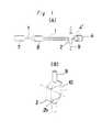
- FIG. 1(A), (B) and Fig. 2One preferred embodiment of the present invention is shown in Fig. 1(A), (B) and Fig. 2, in which
- FIG. 1(A), (B) and Fig. 2designates a laser device for emitting a laser beam 1
- reference numeral 8designates a beam expander for suitably magnifying said laser beam
- reference numeral 2designates a sample cell communicatedly connected with an ultrasonic dispersion bath (not shown) through a piping 9 and continuously supplied with a sample liquid by means of a circulating pump (not shown).
- reference numerals 4, 4'designates detectors each formed of, for example, a silicon photodiode for detecting a light which has passed through said sample cell 2 and has been diffracted-scattered by the particles in the sample.
- the sample cell 2 according to the present inventionis provided with a beveled portion 10 formed on an outer surface 2b on the radiating side thereof, as shown in Fig. 1(B).
- the sample cell 2is made of a material, such as glass (for example quartz and BK-7 glass), superior in light-transmissivity, and having an external form and an internal space 2a of a light-transmissive portion comprising a rectangular section.
- glassfor example quartz and BK-7 glass
- superior in light-transmissivityand having an external form and an internal space 2a of a light-transmissive portion comprising a rectangular section.
- Said beveled portion 10is formed in one edge portion of said outer surface 2b on the radiating side (light output side) of the sample cell 2 to substantially increase an angle between a scattered light h' and the beveled portion 10 in order to take said scattered light 5' out of the sample cell 2, whereby detecting the scattered light 5' by means of said detector 4', as above described.
- a scattered light 5 having a small scattering anglewhich has passed through the outer surface 2b of the sample cell 2 which is not beveled, is detected by means of said separately provided detector 4.
- both said scattered light 5 and the scattered light 5'may be detected by means of only one detector 4 by providing a collecting lens behind the sample cell 2.
- FIG. 3shows another preferred embodiment of the present invention.
- a sample cell 2is provided with a beveled portion 11 formed in an edge portion opposite to that in the above described preferred embodiment of an outer surface 2b on the radiating side thereof and a detector 4' is provided in said beveled portion 11 to detect a scattered light 5'.
- a scattered light 5is detected by means of a detector 4 provided in the same manner as in the above described preferred embodiment.
- beveled portions 10, 11 described in the present preferred embodimentsare differently set depending upon the material and size of the sample cell, the refractive index of the dispersion medium and the like, so that they may be suitably and optionally selected.
- the beveled portionis not limited by the flat surface as in the above described preferred embodiment, that is it may also be a curved surface.
Landscapes
- Chemical & Material Sciences (AREA)
- Dispersion Chemistry (AREA)
- Physics & Mathematics (AREA)
- Health & Medical Sciences (AREA)
- Life Sciences & Earth Sciences (AREA)
- Analytical Chemistry (AREA)
- Biochemistry (AREA)
- General Health & Medical Sciences (AREA)
- General Physics & Mathematics (AREA)
- Immunology (AREA)
- Pathology (AREA)
- Investigating Or Analysing Materials By Optical Means (AREA)
- Optical Measuring Cells (AREA)
Description
- The present invention relates to an apparatus as claimed in the preamble of
claim 1 for measuring a distribution of the size of diffraction-scattering type particles. - Fig. 4 shows main parts in a conventional general apparatus for measuring a distribution of the size of diffraction-scattering type particles. Referring to Fig. 4,
reference numeral 1 designates a laser beam emitted from a laser device (not shown), reference numeral 2' designates a rectangular cylindrical sample cell having a rectangular sectioned external form and aninternal space 2a' which is continuously supplied with a sample liquid from an ultrasonic diffusion bath (not shown) by means of a circulating pump (not shown),reference numeral 3 designates a condenser lens for collecting a light, which has transmitted through said sample cell 2', and a light, which has been scattered (diffracted) by particles contained in said sample liquid within the sample cell, andreference numeral 4 designates a detector formed of, for example, a silicon photodiode for detecting a light fromsaid condenser lens 3. - In the above described apparatus for measuring a distribution of particle size, upon applying said
laser beam 1 to the sample cell 2' under the condition that saidinternal space 2a' of the sample cell 2' is continuously supplied with the sample liquid, a part of thelaser beam 1 is applied to said particles in the sample liquid within the sample cell 2' to be turned into a scattered (diffracted)light 5, whereby arriving at saiddetector 4 through thecondenser lens 3. - However, in the apparatus for measuring a distribution of particle size having the above described construction, as shown in Fig. 5(A), (B), in the case where an angle φ1 between said
light 5 scattered by theparticles 6 and anouter surface 2b' of thesample cell 2 is large, that is a scattering angle θ1 from theparticles 6 is small (for example θ1< about 50° in the case where a dispersion medium is water), thescattered light 5 arrives at thedetector 4 through the sample cell 2'. But in the case where an angle φ2 between the scattered light 5' and saidouter surface 2b' of thesample cell 2 is small, that is a scattering angle θ2 from theparticles 6 is large (θ1 ≥ about 50° in the case where a dispersion medium is water similarly), the scattered light 5' is totally reflected by theouter surface 2b' of thesample cell 2 without transmitting through the sample cell 2'. In general, the smaller the particle size is, the larger the scattering angle θ is, so that, with the conventional apparatus for measuring a distribution of the size of diffraction-scattering type particles, sizes of particles having reduced diameters are difficult to measure and thus the measurement of a distribution of particle size over a wide range is impossible. - A further conventional particle analyzing device (JP-A-62-168033) includes a laser light source and an image forming lens passed by a laser beam to illuminate sample particles in a flow cell. Further, scattered light is detected by a photoelectric detector through a condenser lens to obtain information on the size of the sample particles.
- The light input and output surfaces of the sample cell are parallel to each other and perpendicular to the optical axis of the image forming lens and the condenser lens for receiving forward scattered light.
- Another conventional fine particle measuring system (US-A-4 906 094) comprises a flow cell having a rectangular cross section. An incident block is attached to the light input side while a light trap is provided at the light output side in order to stop the undiffracted-unscattered light beam. The output surface of the flow cell is perpendicular to the optical axis of the system.
- Regarding the above described matters it is an object of the present invention to provide an apparatus having a relatively simple construction for measuring a distribution of the size of diffraction-scattering type particles capable of measuring also with high accuracy a size of particles having a reduced diameter in order to obtain a distribution of the particle size over a wide range.
- In order to achieve the above described object an apparatus according to the preamble of
claim 1 is provided with the characterizing features thereof. - According to the construction as claimed in
claim 1 the angle between the scattered light and the outer surface of the sample cell can be substantially increased by beveling a part of the outer surface of the sample cell, so that the scattered light, which has been unable to pass through the outer surface of sample cell on account of the formally reduced angle between the scattered light and the outer surface of the sample cell, can now be measured and thus the distribution of particle size of the particles having small diameters to large diameters can be measured over a wide range. - One preferred embodiment of the present invention is shown in Fig. 1(A), (B) and Fig. 2, in which
- Fig. 1(A) is a block diagram showing main parts of an apparatus for measuring a distribution of the size of diffraction-scattering type particles;
- Fig. 1(B) is a whole perspective view showing a sample cell of said apparatus; and
- Fig. 2 is a drawing for describing an operation of the sample cell shown in Fig. 1(B).
- Fig. 3 shows another preferred embodiment of the present invention and an operation of a sample cell.
- Fig. 4 and 5 is a drawing for describing the prior art, respectively.
- Preferred embodiments of the present invention will be described below with reference to the drawings.
- One preferred embodiment of the present invention is shown in Figs. 1(A), (B) and Fig. 2. Referring to Fig. 1(A),
reference numeral 7 designates a laser device for emitting alaser beam 1,reference numeral 8 designates a beam expander for suitably magnifying said laser beam,reference numeral 2 designates a sample cell communicatedly connected with an ultrasonic dispersion bath (not shown) through a piping 9 and continuously supplied with a sample liquid by means of a circulating pump (not shown). andreference numerals 4, 4' designates detectors each formed of, for example, a silicon photodiode for detecting a light which has passed through saidsample cell 2 and has been diffracted-scattered by the particles in the sample. - The
sample cell 2 according to the present invention is provided with abeveled portion 10 formed on anouter surface 2b on the radiating side thereof, as shown in Fig. 1(B). - A construction and an operation of the
sample cell 2 are below described with reference to also Fig. 2. Thesample cell 2 is made of a material, such as glass (for example quartz and BK-7 glass), superior in light-transmissivity, and having an external form and aninternal space 2a of a light-transmissive portion comprising a rectangular section. - Said
beveled portion 10 is formed in one edge portion of saidouter surface 2b on the radiating side (light output side) of thesample cell 2 to substantially increase an angle between a scattered light h' and thebeveled portion 10 in order to take said scattered light 5' out of thesample cell 2, whereby detecting the scattered light 5' by means of said detector 4', as above described. In addition, ascattered light 5 having a small scattering angle, which has passed through theouter surface 2b of thesample cell 2 which is not beveled, is detected by means of said separately provideddetector 4. Alternatively, both said scatteredlight 5 and the scattered light 5' may be detected by means of only onedetector 4 by providing a collecting lens behind thesample cell 2. - Fig. 3 shows another preferred embodiment of the present invention. A
sample cell 2 is provided with abeveled portion 11 formed in an edge portion opposite to that in the above described preferred embodiment of anouter surface 2b on the radiating side thereof and a detector 4' is provided in saidbeveled portion 11 to detect a scattered light 5'. In addition, ascattered light 5 is detected by means of adetector 4 provided in the same manner as in the above described preferred embodiment. - Said angles of said
beveled portions
Claims (7)
- Apparatus for measuring the particle size distribution of a liquid sample containing particles of the type which scatter and diffract light, comprising a sample cell (2), a light source (7), and detecting means (4), the sample cell being of substantially rectangular external cross section (2b), with an internal space (2a) of rectangular cross section, through which the sample under investigation is caused to flow, said source being arranged to direct coherent light onto one of the longer sides of the rectangular cell, such that light transmitted straight through the cell emerges on the same line from the other of the longer sides of the cell, the detecting means being arranged to detect light scattered and diffracted by the particles in the flowing sample, emerging at various angles with respect to said straight through line, characterised in that
a corner of the sample cell on the light output side thereof is bevelled, such that light, scattered and diffracted by particles in the sample at large angles, and which would otherwise be totally internally reflected at the output surface of the cell if this were flat and parallel to the input surface over the same length as the input surface, will pass through the bevelled surface, and the detecting means is arranged to be able to detect light emerging from both the part of the output surface which is parallel to the input surface and light emerging from the bevelled surface. - The apparatus as claimed in claim 1,characterized in that the beveled surface (10, 11) of the sample cell (2) is a flat surface.
- The apparatus as claimed in claim 1,characterized in that the beveled surface (10, 11) of the sample cell (2) is a curved surface.
- The apparatus as claimed in one of the claims 1 to 3,characterized in that separate detectors (4, 4') are provided for detecting a light (5, 5') diffracted-scattered under a small/large diffraction-scattering angle.
- The apparatus as claimed in one of the claims 1 to 3,characterized in that the light (5, 5') diffracted-scattered under small and large diffraction-scattering angles is detected by means of merely one detector, and in that a collecting lens is provided between said detector and the sample cell (2).
- The apparatus as claimed in claim 4,characterized in that the detectors (4, 4') for detecting the diffracted-scattered light (5, 5') having small/large diffraction-scattering angles are positioned on the same side of the coherent input light beam (1).
- The apparatus as claimed in claim 4,characterized in that the detectors (4, 4') for detecting the diffracted-scattered light (5, 5') having small/ large diffracti.on-scattering angles are positioned on different sides of the coherent input light beam (1).
Applications Claiming Priority (2)
| Application Number | Priority Date | Filing Date | Title |
|---|---|---|---|
| JP2071674AJP2694304B2 (en) | 1990-03-19 | 1990-03-19 | Light diffraction, scattering type particle size distribution analyzer |
| JP71674/90 | 1990-03-19 |
Publications (2)
| Publication Number | Publication Date |
|---|---|
| EP0447991A1 EP0447991A1 (en) | 1991-09-25 |
| EP0447991B1true EP0447991B1 (en) | 1997-01-08 |
Family
ID=13467370
Family Applications (1)
| Application Number | Title | Priority Date | Filing Date |
|---|---|---|---|
| EP19910104060Expired - LifetimeEP0447991B1 (en) | 1990-03-19 | 1991-03-15 | Apparatus for measuring the distribution of the size of diffraction-scattering type particles |
Country Status (4)
| Country | Link |
|---|---|
| EP (1) | EP0447991B1 (en) |
| JP (1) | JP2694304B2 (en) |
| AU (1) | AU636457B2 (en) |
| DE (1) | DE69123990T2 (en) |
Families Citing this family (7)
| Publication number | Priority date | Publication date | Assignee | Title |
|---|---|---|---|---|
| DE69129260T2 (en)* | 1990-11-03 | 1998-11-19 | Horiba Ltd | Device for measuring the particle size distribution |
| DE4215908A1 (en)* | 1992-05-14 | 1993-11-18 | Ubbo Prof Dr Ricklefs | Optical particle size measurement appts. e.g. for clean room - periodically modulates light incident on measuring vol. e.g by varying light source power or using grating, acoustic=optic modulator or hologram, and detects scattered light. |
| FR2713773B1 (en)* | 1993-12-09 | 1996-03-01 | Sematech Sarl | Laser particle size analyzer with prism effect. |
| FR2841983B1 (en)* | 2002-07-02 | 2004-10-08 | Formulaction | METHOD AND DEVICE FOR MEASURING A LIGHT FLOW RETRODUCTED BY A DISPERSE MEDIUM, NOT PERTURBED BY REFLECTIONS AT THE INTERFACES |
| GB2411002B (en)* | 2004-02-11 | 2006-12-20 | Facility Monitoring Systems Lt | Particle counter for liquids |
| US8879797B2 (en)* | 2012-05-25 | 2014-11-04 | Fluid Imaging Technologies, Inc. | System and method for total internal reflection enhanced imaging flow cytometry |
| US9983115B2 (en) | 2015-09-21 | 2018-05-29 | Fluid Imaging Technologies, Inc. | System and method for monitoring particles in a fluid using ratiometric cytometry |
Family Cites Families (7)
| Publication number | Priority date | Publication date | Assignee | Title |
|---|---|---|---|---|
| JPS5536352U (en)* | 1978-09-01 | 1980-03-08 | ||
| US4284355A (en)* | 1979-10-29 | 1981-08-18 | Ortho Diagnostics, Inc. | Automated method for cell volume determination |
| GB2095827B (en)* | 1981-03-31 | 1985-07-03 | Wool Dev Int | Measurement of diameters of small objects |
| ATE91348T1 (en)* | 1985-09-09 | 1993-07-15 | Commw Scient Ind Res Org | FLOW CELL FOR ANALYZING SUBSTANCES. |
| US4906094A (en)* | 1987-04-23 | 1990-03-06 | Sumitomo Chemical Co. Ltd. | Fine particle measuring method and system and a flow cell for use in the system |
| JPH01263534A (en)* | 1988-04-15 | 1989-10-20 | Hitachi Ltd | Counting apparatus for particulates |
| JPH06268033A (en)* | 1993-03-15 | 1994-09-22 | Matsushita Electron Corp | Wire bonding apparatus |
- 1990
- 1990-03-19JPJP2071674Apatent/JP2694304B2/ennot_activeExpired - Lifetime
- 1991
- 1991-03-05AUAU72614/91Apatent/AU636457B2/ennot_activeCeased
- 1991-03-15EPEP19910104060patent/EP0447991B1/ennot_activeExpired - Lifetime
- 1991-03-15DEDE1991623990patent/DE69123990T2/ennot_activeExpired - Fee Related
Also Published As
| Publication number | Publication date |
|---|---|
| DE69123990T2 (en) | 1997-07-17 |
| EP0447991A1 (en) | 1991-09-25 |
| JPH03269238A (en) | 1991-11-29 |
| DE69123990D1 (en) | 1997-02-20 |
| JP2694304B2 (en) | 1997-12-24 |
| AU7261491A (en) | 1991-09-19 |
| AU636457B2 (en) | 1993-04-29 |
Similar Documents
| Publication | Publication Date | Title |
|---|---|---|
| US4154529A (en) | System for detecting reflected laser beams | |
| JP3140664B2 (en) | Foreign matter inspection method and apparatus | |
| EP0899548B1 (en) | Cross-correlation method and apparatus for suppressing the effects of multiple scattering | |
| US5565984A (en) | Re-entrant illumination system for particle measuring device | |
| EP1650548A3 (en) | Surface plasmon sensor | |
| EP0617273A3 (en) | Optical method and device for analyzing substances on sensor surfaces. | |
| KR840003359A (en) | Method and apparatus for detecting nonuniformity of substrate film | |
| EP0196168B1 (en) | Fiber optic doppler anemometer | |
| WO1998052025A1 (en) | Surface inspection instrument and surface inspection method | |
| EP0447991B1 (en) | Apparatus for measuring the distribution of the size of diffraction-scattering type particles | |
| KR950014849A (en) | Photometric detectors scattered by thin films of colloidal media | |
| US4893929A (en) | Particle analyzing apparatus | |
| JPS6273143A (en) | Optical type web monitor device | |
| US4771181A (en) | Method for detecting dripping droplet with refracted and reflected light | |
| US5742382A (en) | Refractometer | |
| JPS63140904A (en) | Scattered light measuring device | |
| EP0559529B1 (en) | Laser granulometer | |
| US5212393A (en) | Sample cell for diffraction-scattering measurement of particle size distributions | |
| JPH03289504A (en) | Bubble measuring apparatus | |
| JP2526862Y2 (en) | Light diffraction, scattering type particle size distribution analyzer | |
| JPH06241974A (en) | Grain size distribution measuring device | |
| EP0509847A2 (en) | Measuring the cross-sectional distribution of the refractive index of optical waveguides | |
| EP0509848A2 (en) | Measuring the cross-sectional distribution of the refractive index of an optical waveguide | |
| JPS6258139A (en) | Particle measurement method and device | |
| JPH045556A (en) | Method and device for flaw inspection of surface of sphere |
Legal Events
| Date | Code | Title | Description |
|---|---|---|---|
| PUAI | Public reference made under article 153(3) epc to a published international application that has entered the european phase | Free format text:ORIGINAL CODE: 0009012 | |
| AK | Designated contracting states | Kind code of ref document:A1 Designated state(s):DE FR GB | |
| 17P | Request for examination filed | Effective date:19920130 | |
| 17Q | First examination report despatched | Effective date:19940816 | |
| GRAG | Despatch of communication of intention to grant | Free format text:ORIGINAL CODE: EPIDOS AGRA | |
| GRAH | Despatch of communication of intention to grant a patent | Free format text:ORIGINAL CODE: EPIDOS IGRA | |
| GRAH | Despatch of communication of intention to grant a patent | Free format text:ORIGINAL CODE: EPIDOS IGRA | |
| GRAA | (expected) grant | Free format text:ORIGINAL CODE: 0009210 | |
| AK | Designated contracting states | Kind code of ref document:B1 Designated state(s):DE FR GB | |
| REF | Corresponds to: | Ref document number:69123990 Country of ref document:DE Date of ref document:19970220 | |
| ET | Fr: translation filed | ||
| PLBE | No opposition filed within time limit | Free format text:ORIGINAL CODE: 0009261 | |
| STAA | Information on the status of an ep patent application or granted ep patent | Free format text:STATUS: NO OPPOSITION FILED WITHIN TIME LIMIT | |
| 26N | No opposition filed | ||
| PGFP | Annual fee paid to national office [announced via postgrant information from national office to epo] | Ref country code:GB Payment date:19980306 Year of fee payment:8 | |
| PGFP | Annual fee paid to national office [announced via postgrant information from national office to epo] | Ref country code:FR Payment date:19980310 Year of fee payment:8 | |
| PGFP | Annual fee paid to national office [announced via postgrant information from national office to epo] | Ref country code:DE Payment date:19980320 Year of fee payment:8 | |
| PG25 | Lapsed in a contracting state [announced via postgrant information from national office to epo] | Ref country code:GB Free format text:LAPSE BECAUSE OF NON-PAYMENT OF DUE FEES Effective date:19990315 | |
| GBPC | Gb: european patent ceased through non-payment of renewal fee | Effective date:19990315 | |
| PG25 | Lapsed in a contracting state [announced via postgrant information from national office to epo] | Ref country code:FR Free format text:LAPSE BECAUSE OF NON-PAYMENT OF DUE FEES Effective date:19991130 | |
| REG | Reference to a national code | Ref country code:FR Ref legal event code:ST | |
| PG25 | Lapsed in a contracting state [announced via postgrant information from national office to epo] | Ref country code:DE Free format text:LAPSE BECAUSE OF NON-PAYMENT OF DUE FEES Effective date:20000101 |