EP0443928A1 - Training method and device for vehicle driving - Google Patents
Training method and device for vehicle drivingDownload PDFInfo
- Publication number
- EP0443928A1 EP0443928A1EP91400417AEP91400417AEP0443928A1EP 0443928 A1EP0443928 A1EP 0443928A1EP 91400417 AEP91400417 AEP 91400417AEP 91400417 AEP91400417 AEP 91400417AEP 0443928 A1EP0443928 A1EP 0443928A1
- Authority
- EP
- European Patent Office
- Prior art keywords
- image
- screen
- rear view
- images
- cockpit
- Prior art date
- Legal status (The legal status is an assumption and is not a legal conclusion. Google has not performed a legal analysis and makes no representation as to the accuracy of the status listed.)
- Granted
Links
- 238000000034methodMethods0.000titleclaimsabstractdescription13
- 238000012549trainingMethods0.000titleclaimsabstractdescription8
- 230000003287optical effectEffects0.000claimsdescription13
- 238000005070samplingMethods0.000claimsdescription5
- 238000004088simulationMethods0.000description10
- 230000000704physical effectEffects0.000description5
- 238000006243chemical reactionMethods0.000description4
- 230000000007visual effectEffects0.000description4
- 238000004364calculation methodMethods0.000description3
- 230000000694effectsEffects0.000description3
- 238000010586diagramMethods0.000description2
- 238000012545processingMethods0.000description2
- 230000008033biological extinctionEffects0.000description1
- 230000015572biosynthetic processEffects0.000description1
- 239000000470constituentSubstances0.000description1
- 230000000881depressing effectEffects0.000description1
- 239000000284extractSubstances0.000description1
- 238000004519manufacturing processMethods0.000description1
- 238000012986modificationMethods0.000description1
- 230000004048modificationEffects0.000description1
- 210000001747pupilAnatomy0.000description1
- 238000009877renderingMethods0.000description1
- 238000003786synthesis reactionMethods0.000description1
- 238000012546transferMethods0.000description1
- 238000012800visualizationMethods0.000description1
Images


Classifications
- G—PHYSICS
- G09—EDUCATION; CRYPTOGRAPHY; DISPLAY; ADVERTISING; SEALS
- G09B—EDUCATIONAL OR DEMONSTRATION APPLIANCES; APPLIANCES FOR TEACHING, OR COMMUNICATING WITH, THE BLIND, DEAF OR MUTE; MODELS; PLANETARIA; GLOBES; MAPS; DIAGRAMS
- G09B9/00—Simulators for teaching or training purposes
- G09B9/02—Simulators for teaching or training purposes for teaching control of vehicles or other craft
- G09B9/04—Simulators for teaching or training purposes for teaching control of vehicles or other craft for teaching control of land vehicles
- G09B9/05—Simulators for teaching or training purposes for teaching control of vehicles or other craft for teaching control of land vehicles the view from a vehicle being simulated
Definitions
- the present inventionrelates to the equipment and techniques which make it possible to simulate the conditions for piloting mobile vehicles in order to provide training for pupils in driving such vehicles. It is more particularly intended for applications relating to driving, in particular that of passenger cars and other land vehicles, whether these are vehicles equipped with wheels or tracked vehicles.
- the inventionproposes to obtain a simulation closer to the real conditions of driving, considered in all cases where the driver must not only drive his vehicle according to an environment he observe in front of him, but must also monitor what is going on behind him through mirrors.
- the subject of the inventionis a method for driving training in land vehicles, according to which a sequence of images is displayed on a screen arranged opposite a cockpit for a student driver.
- a sequence of imagesis displayed on a screen arranged opposite a cockpit for a student driver.
- we evolve according to orders determined from said cockpitcharacterized in that one thus visualizes on said screen, both a main frontal image and at least one secondary image of rear view which is made visible on an associated rear view mirror which comprises the cockpit and in that said main image and said secondary image are computer generated images generated by a computer from a database containing the description of a three-dimensional road circuit.
- the inventionlends itself particularly well to the reproduction of the driver's visual environment by the technique of generating computer generated images.
- the main images and the secondary imagescan be simultaneously generated on the same screen by a computer from a database containing the description of a three-dimensional road circuit.
- the fact of generating all these images on the same screenis particularly advantageous and leads to a simplified or stylized representation of the rear view images with respect to the front main image.
- these secondary imagesare generated and embedded in the main image from information extracted from the database to correspond to fields of vision at the rear of the driver, as is the case for a real cockpit of a motor vehicle, while the main image is generated from information corresponding to a forward field of vision.
- the inventionalso relates to a device for driving training comprising, facing a cockpit for a student driver, at least one display screen, characterized in that said images are generated by a computer from a database containing the description of a three-dimensional road circuit, and in that it comprises, in addition to the first means of generating a main image front as a function of the controls of said cockpit, at least second means for generating at least a first secondary rear view image embedded in said front image on a first portion of said screen and first optical means for removing and returning said first secondary image to an associated rear view mirror in the cockpit.
- the video monitor screenis integrated in a casing which hides the screen in the lower part at the level of secondary images corresponding to at least one side mirror and this casing contains a mirror of returning secondary images to said side mirror.
- the devicefurther comprises two video monitor screens suitable for reproducing lateral main images on either side of the frontal main image.
- FIG. 1schematically illustrates the different fields of vision available to a driver of a motor vehicle and which the invention seeks to reproduce in his simulation device.
- the rear view fieldscorrespond to those of an equipped vehicle of a left-hand drive, the first rear lateral rear view field being that delivered by the left exterior mirror 8 and the second rear lateral rear view field 9 being that delivered by the right exterior mirror 10.
- the first rear side rear view fieldwould be that delivered by a first right side exterior mirror and the second rear side view field would be that delivered by a second left side exterior mirror .
- the choice of the number of rear view imagesessentially depends on the type of vehicle whose driving is to be simulated. We can for example only generate the two lateral rearview images in the case of a heavy vehicle or generate the central rearview image and the first lateral rearview image if it is desired to simulate a vehicle not provided with a second side mirror.
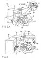
- FIG. 2Apartially represents a cockpit of a driving simulator showing the display console of this cockpit.
- the cockpit of an automobile simulatorcomprises, in addition to the driving instruments reproduced from a motor vehicle such as the steering wheel 11, the dashboard 12, the gearshift lever 13, the hand brake, the crankset comprising an accelerator, brake and clutch pedal and the seat 14, a display console 15 embodied in the form of a television screen 16, a loudspeaker, a module for rendering physical effects at the wheel, and a control keyboard available to an instructor to allow the scenarios and the landscapes reproduced on the screen to evolve; a student driver 17 taking place on the seat 14 as it would in a motor vehicle.
- a motor vehiclesuch as the steering wheel 11, the dashboard 12, the gearshift lever 13, the hand brake, the crankset comprising an accelerator, brake and clutch pedal and the seat 14
- a display console 15embodied in the form of a television screen 16, a loudspeaker, a module for rendering physical effects at the wheel, and a control keyboard available to an instructor to allow the scenarios and the landscapes reproduce
- the control of the deviceis placed under the control of a computer (not shown) which receives information from the control keyboard of the instructor, information on the position of the handbrake, information indicating, depending on from the position of the gear lever 13, the speed selected by the driver raises 17, and information from pedal sensors indicating the degree of depressing of the accelerator, brake or clutch pedals, or a simultaneous action on many of these pedals.
- a simulatoralso generally includes a module for restoring physical effects to the steering wheel, provided with a sensor detecting the angular orientation of the steering wheel 11 and a motor member making it possible to give a feedback of the reaction forces of the steering and the wheels on the steering wheel 11.
- the computercontrols the engine of the module for restoring physical effects to the steering wheel to simulate the steering reaction forces on the steering wheel, the warning lights and dials appearing on the dashboard 12, the sound effects produced by the loudspeaker, and the images to be displayed on the screen 16.
- the computeralso includes electronic interface with the cockpit equipment.
- the computercomprises first means of generating a main front synthesis image 18 intended to be projected on the screen 16. These first means of generating images use a database (FIG. 6) to do this. which images are generated.
- This databasecontains the three-dimensional description of one or more road circuits made up of roads, buildings, trees, vehicles, etc. It provides driving scenes in town, on the road and on the highway.
- the computerextracts from the database the elements making it possible to reconstruct the frontal vision that the driver must have 17 as a function of the evolution of the position and the orientation of the vehicle on the road circuit.
- This main frontal imagecorresponds to the direct field of vision of the driver towards the front of the vehicle designated by the reference 3 in FIG. 1.
- the computeralso comprises second means for generating a first secondary rear view image 19 (FIG. 2B) intended to be embedded in the main front image 18 and constituting the rear central rear view field designated by the reference 5 in FIG. 1
- a central mirror 20is arranged in front of this first secondary image of rear view and constitutes first means of sampling and optical return of this first secondary image.
- the rear view mirror 20is for this purpose constituted by a Fresnel lens ensuring an optical transfer such that the secondary image 19 is deflected towards the eyes of the student driver 17.
- the purpose of this Fresnel lensis to make the image 19 directional to force the student driver to adjust the mirror 20 before starting a driving session, and this in the same way that a driver must adjust his mirror before driving a real vehicle.
- This Fresnel lens systemcan be replaced, in another variant, by a directive filter, or any other system having the same function, such as for example a modification of the secondary image embedded in the main image under the effect of the action by the student on an adjustment system having the effect of modifying the embedded image by action on the second generation means.
- the mirror 20can for example be fixed to the by means of a fixing lug 21 on the upper part of the screen 16.
- the fixing lug 21preferably has a ball joint adjustment system similar to that of an actual rear view mirror.
- the computeralso includes third means for generating a second secondary rear view image (22 FIG. 3A), embedded in the main front image 18 and reproducing a first rear lateral rear view field designated by the reference 7 in FIG. 1, as well as possibly fourth means for generating a third secondary rear view image (23 FIG. 3A), embedded in the main front image 18 and reproducing the second rear lateral rear view field designated by the reference 9 in FIG. 1.
- These two secondary images of lateral rear vieware preferably embedded in the lower part of the front image 18.
- the display console 15also includes a casing 24 constituting second and third means for sampling and optical return of the second and third secondary images respectively to a first side mirror 25 and a second side mirror 26.
- These mirrorsmay consist of conventional mirrors usually fitted to motor vehicles and are fixed for example on either side of the screen 16 on its side walls.
- the mirrors 25 and 26are adjustable in their orientation, obliging the student driver 17 to orient them properly so as to see all of the rear view images 22 and 23 generated on the screen 16.
- the casing 24is shaped so as to mask the secondary images 22 and 23 from the direct vision of the student driver 17. It is internally equipped with two mirrors 27 and 28 respectively reflecting the images 22 and 23 to the mirror 25 or 26 via an opening 29 or 30 formed in a left or right side face of the casing 24.
- the mirrors 27 and 28can be replaced by prisms determining the optical paths between the screen and the mirrors.
- FIG. 3Aschematically represents the respective positions of overlay of the secondary rear view images 19, 22 and 23 in the main image 18 displayed on the screen 16.
- FIG. 3Bschematically shows in top view the optical paths followed by the lateral rear view images 22 and 23 from the screen 16 to the eyes of the student driver represented by point 31. It can be seen that each of these images of side view is first of all returned by being deflected by one of the mirrors 27 or 28 to the associated side view mirror 25 or 26 which itself returns the corresponding image to point 31.
- FIG. 3Cschematically shows in top view the optical path traveled by the first rear view image 19, corresponding to the rear central rear view field, from the screen 16 to the eyes of the student driver represented diagrammatically by point 32.
- this first rear view imagepasses through the rear view mirror 20 which is made up of a Fresnel lens and which, when it is properly oriented, deflects this image towards point 32, thus allowing the student driver to see the rear view image 19 .
- FIG. 4representing a perspective view of the display console 15 illustrating more particularly the optical paths followed from screen 16 up to the eyes of a student driver represented by a point 33
- the front main imagefollows a direct optical path 34 while the secondary images embedded in the main image are deflected to be returned to the point 33.
- the first central rear view imagefollows a path 35 after passing through the rear view mirror 20, and the two secondary lateral rear view images follow respectively paths 36 or 37 which, after having been reflected respectively by the mirrors 27 or 28 of the casing 24, are returned, after passing through one of the openings 29 or 30, by the exterior side mirror 25 or 26 which is associated with them towards point 33.
- FIGS. 3B, 3C and 4which illustrate the convergence of the rear view images presented in the interior mirror 20 and in the exterior mirrors 25 and 26 towards the point representing the eyes of the student driver, clearly show how, according to the invention, one achieves restore to the vision of the student driver, the different fields of vision and rear view, as shown in Figure 1, thus reproducing in simulation the visual environment of the vehicle allowing to be very close to the real conditions of driving.
- the mirrors 20, 25 and 26are adjustable in their orientation so as to reproduce as accurately as possible the actual conditions of driving, the student driver having to modify their orientation as a function, for example, of its size and its position relative to the driving position in order to see the secondary images in their entirety.
- the secondary images 19, 22 and 23are embedded in the main image 18 on portions of the screen 16 which are dimensioned so that the image seen by the student driver in a rear view mirror is smaller than the secondary image embedded in the main image 18. Therefore by changing the orientation of these mirrors, the elevated driver changes the orientation of these rear fields of vision and thus finds himself in very simulated situations close to reality.
- the secondary imagesare in this case partially sampled by the sampling and reference means associated with them, thus making it possible, by adjusting a rear view mirror, to modify the sampled portion of the secondary image which is associated with it.
- FIG. 5represents a partial perspective view of an alternative embodiment of a driving simulation cockpit according to the invention comprising two lateral screens 38 and 39 located on either side of the screen 16 and allowing display a wide image simulating not only on the screen 16 the front main image 18 but also on the screens 38 and 39 of the lateral images 40 and 41 corresponding to the lateral fields of vision of the vehicle, thus completing the environment of the road circuit by reproducing a complete direct field of vision of the driver such as that designated by the reference 3 in FIG. 1.
- the computercomprises for this purpose fifth means of generating computer generated images allowing the production of images 40 and 41.
- the screens 38 and 39are arranged with respect to the screen 16 so as to widen the direct field of vision of the student driver 17.
- provisioncan be made to remove the side mirrors 25 and 26 and to embed the secondary rear view images 22 or 23 in the lower part of the screen 38 or 39.
- these lateral screens 38 or 39 and to define the fifth image generation means as a function of this orientationso that these screens display either the direct field of vision of the driver in an enlarged manner, as represented in FIG. 5, or the lateral fields of vision of the vehicle such as those defined in real condition by the vision through the side windows of the vehicle.
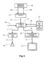
- FIG. 6represents a block diagram of the simulator which, starting from the control members 60 of the vehicle, constituted by the steering wheel 11, the accelerator, the clutch, the brake, the gearbox, and the controls of the control panel on board 12, transmits the driver's actions via a link 62a to a vehicle modeling program 61 which allows the computer to calculate the reactions of the vehicle to the commands of the student driver. These reactions are transmitted by a link 62b to the control members 60 of the vehicle, so as to reproduce the physical effects at the wheel and to control the indicators and dials on the dashboard. This calculation makes it possible to send, via the link 63, the information concerning the position and the angle of the vehicle to a scenario control means 64.
- This scenario control meansreceives, by a link 65, the commands selected by the instructor to influence the course of the scenario, so as to reproduce various traffic conditions and situations risk constituted by obstacles visualized in frontal vision or in rear view.
- the monitorcan select visual effects to reproduce special driving conditions, such as driving at night, in rain or snow, in foggy weather, etc.
- the scenario control means 64receives by a link 66, the data useful for the generation of the main and secondary images coming from a database 67 in which various representations of road circuits are stored making it possible to reproduce traffic conditions in city, on road and highway.
- the scenario control means 64sends, by a link 68, information necessary for the generation of three-dimensional images to a means for generating these images 69 which allows the computer to perform the calculation of the main and secondary images, for frontal vision, for central rear view and for lateral rear view.
- the scenario control means 64sends, by a link 70, the information necessary for updating the database 67 according to the scenario.
- a link 71allows this scenario control means 64 to send to a sound generation means 72 the information making it possible to generate engine, gearbox, bearing and audible warning noises which will be sent by a link 73 to a speaker 74.
- the three-dimensional image generator 69sends the images to be displayed on the screen 16 of the display console via a link 75. These images consist of both the main front view image and the secondary rear view images which will be embedded in the main image.
- the generation of the imagesis carried out by taking from the database 67 the images corresponding to the viewing angle of the image to be generated from the simulated position of the vehicle on the road circuit contained in the database. From this position, the system determines the information to be taken for the generation of the images, taking into account the viewing angle associated with the image to be generated and the point of convergence of the field of vision.
- the information necessary for the generation of the imagesis stored in Cartesian coordinates on the database 67 and is taken from this database to be viewed on the screen according to the viewing angles, the position and the direction printed on the simulated vehicle.
- the secondary rear view imagesare displayed on small portions of the screen, these secondary images are defined with a lower resolution than those of the front images.
- more stylized imagescan be used for the rear view images than for the front image.
- the computergenerates the front image and the rear view images from data from the database as a function of the simulated position of the vehicle in the road circuit, so that the generation of the images is carried out according to of the corresponding viewing angle on the road circuit, but using the same database whatever the image considered.
- the computerhas the possibility of viewing sequences of fixed or animated images, for example with two-dimensional graphics. These sequences will be mainly used in the first lessons to discover and explain to the student how the vehicle's control command devices work.
- the computertakes into account the state of the various controls on which the student acts, such as the ignition key, the lighting and warning controls, the position of the steering wheel 11, pedals, speed 13, handbrake, seat belt and instructor's keyboard. It also performs real-time vehicle dynamics modeling and engine, gearbox, clutch, braking, grip, steering functions.
- Such algorithmic processingmakes it possible to calculate at any time the new state of the vehicle, that is to say the position, the orientation, the speed as well as the state of the various instruments and indicators as a function of the commands printed by the student, conditions related to the simulated external environment and the previous state of the vehicle.
- the computeralso ensures the generation of outputs, such as the control of the dashboard speedometer, the generation of physical effects in the steering wheel, the lighting and extinction of the dashboard lights, the own sounds driving and instructional voice messages.
- the processing speed of the computeris such that the above calculations can be repeated 15 to 20 times per second.
- the method and device thus describedmakes it possible to obtain a simulation closer to the real conditions of driving a car, in particular by reproducing not only the environment which the driver raises in front of him under real conditions, but also by reproducing the environment. rear of the vehicle through the mirrors.
Landscapes
- Engineering & Computer Science (AREA)
- Theoretical Computer Science (AREA)
- Educational Technology (AREA)
- Business, Economics & Management (AREA)
- Physics & Mathematics (AREA)
- Educational Administration (AREA)
- Aviation & Aerospace Engineering (AREA)
- General Physics & Mathematics (AREA)
- Control Of Velocity Or Acceleration (AREA)
- Fittings On The Vehicle Exterior For Carrying Loads, And Devices For Holding Or Mounting Articles (AREA)
- Rehabilitation Tools (AREA)
- Devices For Indicating Variable Information By Combining Individual Elements (AREA)
- Processing Or Creating Images (AREA)
Abstract
Description
Translated fromFrenchLa présente invention concerne les équipements et techniques qui permettent de simuler les conditions de pilotage d'engins mobiles pour assurer l'entraînement d'élèves à la conduite de tels engins. Elle s'adresse plus particulièrement aux applications concernant la conduite automobile, notamment celle des voitures de tourisme et autres véhicules terrestres, qu'il s'agisse de véhicules équipés de roues ou de véhicules chenillés.The present invention relates to the equipment and techniques which make it possible to simulate the conditions for piloting mobile vehicles in order to provide training for pupils in driving such vehicles. It is more particularly intended for applications relating to driving, in particular that of passenger cars and other land vehicles, whether these are vehicles equipped with wheels or tracked vehicles.
Diverses techniques plus ou moins complexes et coûteuses ont déjà été proposées pour simuler un paysage en défilement devant un conducteur élève s'entraînant dans un poste de pilotage fixe. On utilise pour cela un écran de visualisation d'images que l'on place face au poste de pilotage et sur lequel on visualise des séquences d'images extraites d'enregistrements préalables, qui peuvent être soit des enregistrements cinématographiques ou vidéo de paysages réels comme dans la demande de brevet français n° 83 20136 déposée 15 décembre 1983, publiée sous le n° 2 556 866, soit des images de synthèse.Various more or less complex and costly techniques have already been proposed to simulate a scrolling landscape in front of a student driver training in a fixed cockpit. For this, an image display screen is used which is placed opposite the cockpit and on which are displayed sequences of images extracted from prior recordings, which may be either cinematographic or video recordings of real landscapes such as in French patent application No. 83 20136 filed December 15, 1983, published under No. 2,556,866, or synthetic images.
Par rapport aux techniques connues, l'invention se propose d'obtenir une simulation plus proche des conditions réelles de la conduite automobile, considérée dans tous les cas où le conducteur ne doit pas seulement piloter son engin en fonction d'un environnement qu'il observe devant lui, mais doit également surveiller ce qui se passe derrière lui par l'intermédiaire de rétroviseurs.Compared to known techniques, the invention proposes to obtain a simulation closer to the real conditions of driving, considered in all cases where the driver must not only drive his vehicle according to an environment he observe in front of him, but must also monitor what is going on behind him through mirrors.
A cette fin, l'invention a pour objet un procédé pour l'entraînement à la conduite de véhicules terrestres, suivant lequel on visualise sur un écran disposé face à un poste de pilotage pour un conducteur élève, une séquence d'images que l'on fait évoluer en fonction de commandes déterminées depuis ledit poste de pilotage, caractérisé en ce que l'on visualise ainsi sur ledit écran, à la fois une image principale frontale et au moins une image secondaire de rétrovision qui est rendue visible sur un rétroviseur associé que comporte le poste de pilotage et en ce que ladite image principale et ladite image secondaire sont des images de synthèse générées par un calculateur à partir d'une base de données contenant la description d'un circuit routier en trois dimensions.To this end, the subject of the invention is a method for driving training in land vehicles, according to which a sequence of images is displayed on a screen arranged opposite a cockpit for a student driver. we evolve according to orders determined from said cockpit, characterized in that one thus visualizes on said screen, both a main frontal image and at least one secondary image of rear view which is made visible on an associated rear view mirror which comprises the cockpit and in that said main image and said secondary image are computer generated images generated by a computer from a database containing the description of a three-dimensional road circuit.
L'invention se prête particulièrement bien à la reproduction de l'environnement visuel du conducteur par la technique de génération d'images de synthèse. Les images principales et les images secondaires peuvent être simultanément générées sur un même écran par un calculateur à partir d'une base de données contenant la description d'un circuit routier en trois dimensions. Le fait de générer toutes ces images sur un même écran est notamment avantageux et conduit à une représentation simplifiée ou stylisée des images de rétrovision par rapport à l'image principale frontale. On comprend par ailleurs que ces images secondaires sont générées et incrustées dans l'image principale à partir d'informations extraites de la base de données pour correspondre à des champs de vision à l'arrière du conducteur, comme c'est le cas pour un véritable poste de pilotage d'un véhicule automobile, alors que l'image principale est générées à partir d'informations correspondant à un champ de vision vers l'avant.The invention lends itself particularly well to the reproduction of the driver's visual environment by the technique of generating computer generated images. The main images and the secondary images can be simultaneously generated on the same screen by a computer from a database containing the description of a three-dimensional road circuit. The fact of generating all these images on the same screen is particularly advantageous and leads to a simplified or stylized representation of the rear view images with respect to the front main image. We also understand that these secondary images are generated and embedded in the main image from information extracted from the database to correspond to fields of vision at the rear of the driver, as is the case for a real cockpit of a motor vehicle, while the main image is generated from information corresponding to a forward field of vision.
L'invention a également pour objet un dispositif pour l'entraînement à la conduite automobile comportant, face à un poste de pilotage pour un conducteur élève, au moins un écran de visualisation, caractérisé en ce que lesdites images sont générées par un calculateur à partir d'une base de données contenant la description d'un circuit routier en trois dimensions, et en ce qu'il comporte, outre des premiers moyens de génération d'une image principale frontale en fonction des commandes dudit poste de pilotage, au moins des deuxièmes moyens de génération d'au moins une première image secondaire de rétrovision incrustée dans ladite image frontale sur une première portion dudit écran et des premiers moyens optiques de prélèvement et de renvoi de ladite première image secondaire vers un rétroviseur associé que comporte le poste de pilotage.The invention also relates to a device for driving training comprising, facing a cockpit for a student driver, at least one display screen, characterized in that said images are generated by a computer from a database containing the description of a three-dimensional road circuit, and in that it comprises, in addition to the first means of generating a main image front as a function of the controls of said cockpit, at least second means for generating at least a first secondary rear view image embedded in said front image on a first portion of said screen and first optical means for removing and returning said first secondary image to an associated rear view mirror in the cockpit.
Dans un mode de réalisation préféré d'un tel dispositif, l'écran de moniteur vidéo est intégré dans un carter qui cache l'écran en partie basse au niveau d'images secondaires correspondant à au moins un rétroviseur latéral et ce carter contient un miroir de renvoi d'images secondaires vers ledit rétroviseur latéral.In a preferred embodiment of such a device, the video monitor screen is integrated in a casing which hides the screen in the lower part at the level of secondary images corresponding to at least one side mirror and this casing contains a mirror of returning secondary images to said side mirror.
Dans une variante de réalisation de l'invention, le dispositif comporte en outre deux écrans de moniteur vidéo propres à restituer des images principales latérales de part et d'autre de l'image principale frontale.In an alternative embodiment of the invention, the device further comprises two video monitor screens suitable for reproducing lateral main images on either side of the frontal main image.
On décrira maintenant plus en détail une forme de réalisation particulière de l'invention qui en fera mieux comprendre les caractéristiques essentielles et les avantages, étant entendu toutefois que cette forme de réalisation est choisie à titre d'exemple et qu'elle n'est nullement limitative. Sa description est illustrée par les dessins annexés, dans lesquels:
- la figure 1 représente schématiquement les différents champs de vision d'un conducteur au volant d'un véhicule automobile;
- la figure 2A représente schématiquement en perspective un dispositif de simulation selon l'invention permettant de donner une représentation de l'environnement visuel du conducteur, et la figure 2B représente une vue agrandie d'un détail de la figure 2A;
- la figure 3A représente schématiquement de face l'écran du dispositif représenté à la figure 1 et les figures 3B et 3C illustrent schématiquement en vue de dessus les moyens de prélèvement et de renvoi des images secondaires selon l'invention;
- la figure 4 représente une vue en perspective d'une console de visualisation selon l'invention illustrant plus particulièrement les trajets optiques;
- la figure 5 représente une vue en perspective d'un deuxième mode de réalisation d'un dispositif de simulation selon l'invention;
- et la figure 6 représente le schéma synoptique du fonctionnememt du dispositif selon l'invention.
- FIG. 1 schematically represents the different fields of vision of a driver behind the wheel of a motor vehicle;
- FIG. 2A schematically represents in perspective a simulation device according to the invention making it possible to give a representation of the visual environment of the driver, and FIG. 2B represents an enlarged view of a detail of FIG. 2A;
- FIG. 3A schematically represents the front of the screen of the device represented in FIG. 1 and the Figures 3B and 3C schematically illustrate a top view of the means for taking and returning the secondary images according to the invention;
- FIG. 4 represents a perspective view of a display console according to the invention illustrating more particularly the optical paths;
- FIG. 5 represents a perspective view of a second embodiment of a simulation device according to the invention;
- and FIG. 6 represents the block diagram of the operation of the device according to the invention.
La figure 1 illustre schématiquement les différents champs de vision dont dispose un conducteur de véhicule automobile et que l'invention cherche à reproduire dans son dispositif de simulation.FIG. 1 schematically illustrates the different fields of vision available to a driver of a motor vehicle and which the invention seeks to reproduce in his simulation device.
Ces champs de vision sont définis par rapport à la position des deux yeux 1 et 2 du conducteur et on y retrouve:
- un champ de vision frontal direct désigné par la
flèche 3 vers l'avant du véhicule et limité par les lignes en traits interrompus 4; - un champ de rétrovision central arrière, désigné par la
flèche 5, et renvoyé par l'intermédiaire d'un rétroviseur intérieur 6 aux yeux du conducteur; - un premier champ de rétrovision latéral arrière, désigné par la
flèche 7, et renvoyé par l'intermédiaire d'un premier rétroviseurextérieur latéral 8 aux yeux du conducteur; - et éventuellement un second champ de rétrovision latéral arrière désigné par la
flèche 9, et renvoyé par l'intermédiaire d'un second rétroviseurextérieur latéral 10 aux yeux du conducteur.
- a direct frontal field of vision designated by the
arrow 3 towards the front of the vehicle and limited by thedashed lines 4; - a rear central rear view field, designated by
arrow 5, and returned via aninterior mirror 6 to the driver's eyes; - a first rear lateral rear view field, designated by
arrow 7, and returned via a first lateralexterior mirror 8 to the driver's eyes; - and possibly a second rear side rear view field designated by
arrow 9, and returned via a second sideexterior mirror 10 to the driver's eyes.
Sur la représentation de la figure 1, les champs de rétrovision correspondent à ceux d'un véhicule équipé d'une conduite à gauche, le premier champ de rétrovision latéral arrière étant celui délivré par le rétroviseur extérieur gauche 8 et le second champ de rétrovision latéral arrière 9 étant celui délivré par le rétroviseur extérieur droit 10.In the representation of FIG. 1, the rear view fields correspond to those of an equipped vehicle of a left-hand drive, the first rear lateral rear view field being that delivered by the left
Dans le cas d'un véhicule équipé d'une conduite à droite, le premier champ de rétrovision latéral arrière serait celui délivré par un premier rétroviseur extérieur latéral droit et le second champ de rétrovision latéral arrière serait celui délivré par un second rétroviseur extérieur latéral gauche.In the case of a vehicle equipped with a right-hand drive, the first rear side rear view field would be that delivered by a first right side exterior mirror and the second rear side view field would be that delivered by a second left side exterior mirror .
Le choix du nombre d'images de rétrovision dépend essentiellement du type de véhicule dont on souhaite simuler la conduite. On peut par exemple ne générer que les deux images de rétrovision latérale dans le cas d'un poids lourd ou générer l'image de rétrovision centrale et la première image de rétrovision latérale si l'on souhaite simuler un véhicule non pourvu d'un deuxième rétroviseur latéral.The choice of the number of rear view images essentially depends on the type of vehicle whose driving is to be simulated. We can for example only generate the two lateral rearview images in the case of a heavy vehicle or generate the central rearview image and the first lateral rearview image if it is desired to simulate a vehicle not provided with a second side mirror.
Le figure 2A représente partiellement un poste de pilotage d'un simulateur de conduite automobile faisant apparaître la console de visualisation de ce poste de pilotage. Le poste de pilotage d'un simulateur automobile comporte, outre les instruments de conduite reproduits d'un véhicule automobile tels que le volant 11, le tableau de bord 12, le levier de changement de vitesse 13, le frein à main, le pédalier comportant une pédale d'accélérateur, de frein et d'embrayage et le siège 14, une console de visualisation 15 matérialisée sous la forme d'un écran de télévision 16, un haut-parleur, un module de restitution des effets physiques au volant, et un clavier de commande à la disposition d'un instructeur pour permettre de faire évoluer les scénarios et les paysages restitués sur l'écran 16 ; un conducteur élève 17 prenant place sur le siège 14 comme il le ferait dans un véhicule automobile.FIG. 2A partially represents a cockpit of a driving simulator showing the display console of this cockpit. The cockpit of an automobile simulator comprises, in addition to the driving instruments reproduced from a motor vehicle such as the
De manière classique, la commande du dispositif est placée sous le contrôle d'un calculateur (non représenté) qui reçoit des informations du clavier de commande de l'instructeur, des informations sur la position du frein à main, des informations indiquant, en fonction de la position du levier de vitesse 13, la vitesse sélectionnée par le conducteur élève 17, et des informations provenant de capteurs du pédalier indiquant le degré d'enfoncement des pédales d'accélérateur, de frein ou d'embrayage, ou une action simultanée sur plusieurs de ces pédales. Un tel simulateur comporte également généralement un module de restitution des effets physiques au volant, muni d'un capteur détectant l'orientation angulaire du volant 11 et un organe moteur permettant de donner une restitution des efforts de réaction de la direction et des roues sur le volant 11.Conventionally, the control of the device is placed under the control of a computer (not shown) which receives information from the control keyboard of the instructor, information on the position of the handbrake, information indicating, depending on from the position of the
En fonction de toutes ces informations, le calculateur commande le moteur du module de restitution des effets physiques au volant pour simuler les efforts de réaction de la direction sur le volant, les voyants et cadrans apparaissant sur le tableau de bord 12, les effets sonores produits par le haut-parleur, et les images à afficher sur l'écran 16. Le calculateur comprend également une électronique d'interface avec les équipements du poste de pilotage.Based on all of this information, the computer controls the engine of the module for restoring physical effects to the steering wheel to simulate the steering reaction forces on the steering wheel, the warning lights and dials appearing on the
Le calculateur comporte des premiers moyens de génération d'une image principale frontale de synthèse 18 destinée à être projetée sur l'écran 16. Ces premiers moyens de génération d'images utilisent pour ce faire une base de données (figure 6) à partir de laquelle les images sont générées. Cette base de données contient la description en trois dimensions d'un ou plusieurs circuits routiers constitués de routes, de bâtiments, d'arbres, de véhicules, etc. Elle permet de disposer de scènes de conduite en ville, sur route et sur autoroute. Lors de la simulation, le calculateur extrait de la base de données les éléments permettant de reconstituer la vision frontale que doit avoir le conducteur élève 17 en fonction de l'évolution de la position et de l'orientation du véhicule sur le circuit routier. Cette image frontale principale correspond au champ de vision direct du conducfeur vers l'avant du véhicule désigné par la référence 3 à la figure 1.The computer comprises first means of generating a main
Le calculateur comporte également des deuxièmes moyens de génération d'une première image secondaire de rétrovision 19 (figure 2B) destinée à être incrustée dans l'image principale frontale 18 et constituant le champ de rétrovision central arrière désigné par la référence 5 à la figure 1. Un rétroviseur central 20 est disposé devant cette première image secondaire de rétrovision et constitue des premiers moyens de prélèvement et de renvoi optique de cette première image secondaire. Le rétroviseur 20 est à cet effet constitué d'une lentille de Fresnel assurant un transfert optique tel que l'image secondaire 19 est déviée en direction des yeux du conducteur élève 17. Cette lentille de Fresnel a pour objectif de rendre directionnelle l'image 19 pour obliger le conducteur élève à régler le rétroviseur 20 avant de commencer une séance de conduite, et ceci de la même manière qu'un conducteur doit régler son rétroviseur avant de conduire un véhicule réel. Ce système de lentille de Fresnel peut être remplacé, dans une autre variante, par un filtre directif, ou tout autre système ayant la même fonction, comme par exemple une modification de l'image secondaire incrustée dans l'image principale sous l'effet de l'action par l'élève sur un système de réglage ayant pour effet de modifier l'image incrustée par action sur les deuxièmes moyens de génération. Le rétroviseur 20 peut être par exemple fixé au moyen d'une patte de fixation 21 sur la partie supérieure de l'écran 16. La patte de fixation 21 dispose de préférence d'un système de réglage à rotule semblable à celui d'un rétroviseur réel.The computer also comprises second means for generating a first secondary rear view image 19 (FIG. 2B) intended to be embedded in the main
Le calculateur comporte également des troisièmes moyens de génération d'une deuxième image secondaire de rétrovision (22 figure 3A), incrustée dans l'image principale frontale 18 et reproduisant un premier champ de rétrovision latéral arrière désigné par la référence 7 à la figure 1, ainsi qu'éventuellement des quatrièmes moyens de génération d'une troisième image secondaire de rétrovision (23 figure 3A), incrustée dans l'image principale frontale 18 et reproduisant le deuxième champ de rétrovision latéral arrière désigné par la référence 9 à la figure 1. Ces deux images secondaires de rétrovision latérale sont de préférence incrustées dans la partie basse de l'image frontale 18.The computer also includes third means for generating a second secondary rear view image (22 FIG. 3A), embedded in the main
La console de visualisation 15 comporte également un carter 24 constituant des deuxième et troisième moyens de prélèvements et de renvoi optique des deuxième et troisième images secondaires respectivement vers un premier rétroviseur latéral 25 et un second rétroviseur latéral 26. Ces rétroviseurs peuvent consister en des rétroviseurs classiques équipant habituellement les véhicules automobiles et sont fixés par exemple de part et d'autre de l'écran 16 sur ses parois latérales. Les rétroviseurs 25 et 26 sont réglables dans leur orientation, obligeant le conducteur élève 17 à les orienter convenablement pour voir la totalité des images de rétrovision 22 et 23 générées sur l'écran 16.The
Le carter 24 est conformé de sorte à masquer les images secondaires 22 et 23 à la vision directe du conducteur élève 17. Il est équipé intérieurement de deux miroirs 27 et 28 renvoyant respectivement les images 22 et 23 vers le rétroviseur 25 ou 26 par l'intermédiaire d'une ouverture 29 ou 30 ménagée dans une face latérale gauche ou droite du carter 24.The
Dans une variante de réalisation des deuxième et troisième moyens de prélèvement et de renvoi optique des images secondaires latérales, les miroirs 27 et 28 peuvent être remplacés par des prismes déterminant les trajets optiques entre l'écran et les rétroviseurs.In an alternative embodiment of the second and third means for removing and optically returning the lateral secondary images, the
La figure 3A représente schématiquement les positions respectives d'incrustation des images secondaires de rétrovision 19, 22 et 23 dans l'image principale 18 visualisée sur l'écran 16.FIG. 3A schematically represents the respective positions of overlay of the secondary
La figure 3B montre schématiquement en vue de dessus les chemins optiques suivis par les images de rétrovision latérale 22 et 23 à partir de l'écran 16 jusqu'aux yeux du conducteur élève représentés par le point 31. On voit que chacune de ces images de rétrovision latérale est tout d'abord renvoyée en étant déviée par l'un des miroirs 27 ou 28 vers le rétroviseur latéral associé 25 ou 26 qui lui-même renvoie l'image correspondante vers le point 31.FIG. 3B schematically shows in top view the optical paths followed by the lateral
La figure 3C montre schématiquement en vue de dessus le chemin optique parcouru par la première image de rétrovision 19, correspondant au champ de rétrovision central arrière, depuis l'écran 16 jusqu'aux yeux du conducteur élève représentés schématiquement par le point 32. On voit que cette première image de rétrovision traverse le rétroviseur 20 qui est constitué d'une lentille de Fresnel et qui, lorsqu'il est bien orienté, dévie cette image vers le point 32, permettant ainsi au conducteur élève de voir l'image de rétrovision 19.FIG. 3C schematically shows in top view the optical path traveled by the first
En référence à la figure 4, représentant une vue en perspective de la console de visualisation 15 illustrant plus particulièrement les trajets optiques suivis depuis l'écran 16 jusqu'aux yeux d'un conducteur élève représentés par un point 33, on voit que l'image principale frontale suit un chemin optique direct 34 alors que les images secondaires incrustées dans l'image principale sont déviées pour être renvoyées au point 33. La première image de rétrovision centrale suit un chemin 35 après avoir traversé le rétroviseur 20, et les deux images secondaires de rétrovision latérale suivent respectivement des chemins 36 ou 37 qui, après avoir été réfléchis respectivement par les miroirs 27 ou 28 du carter 24, sont renvoyées, après avoir traversé l'une des ouvertures 29 ou 30, par le rétroviseur latéral extérieur 25 ou 26 qui leur est associé vers le point 33.With reference to FIG. 4, representing a perspective view of the
Les figures 3B, 3C et 4 qui illustrent la convergence des images de rétrovision présentées dans le rétroviseur intérieur 20 et dans les rétroviseurs extérieurs 25 et 26 vers le point représentant les yeux du conducteur élève, font apparaître clairement comment selon l'invention on parvient à restituer à la vision du conducteur élève, les différents champs de vision et de rétrovision, tel que représenté à la figure 1, reproduisant ainsi en simulation l'environnement visuel du véhicule permettant d'être très proche des conditions réelles de la conduite automobile.FIGS. 3B, 3C and 4 which illustrate the convergence of the rear view images presented in the
Selon une variante de réalisation du dispositif selon l'invention, on prévoit que les rétroviseurs 20, 25 et 26 soient réglables dans leur orientation de manière à reproduire le plus exactement possible les conditions réelles de la conduite automobile, le conducteur élève étant amené à modifier leur orientation en fonction, par exemple, de sa taille et de sa position par rapport au poste de conduite afin de voir les images secondaires dans leur intégralité.According to an alternative embodiment of the device according to the invention, provision is made for the
Selon une autre variante, il est particulièrement avantageux de prévoir que les images secondaires 19, 22 et 23 soient incrustées dans l'image principale 18 sur des portions de l'écran 16 qui sont dimensionnées de manière à ce que l'image vue par l'élève conducteur dans un rétroviseur, soit plus réduite que l'image secondaire incrustée dans l'image principale 18. De ce fait en modifiant l'orientation de ces rétroviseurs, le conducteur élève modifie l'orientation de ces champs de vision arrière et ainsi se trouve dans des situations de simulation très proches de la réalité.According to another variant, it is particularly advantageous to provide that the
Les images secondaires sont dans ce cas prélevées partiellement par les moyens de prélèvement et de renvoi qui leur sont associés, permettant ainsi par le réglage d'un rétroviseur de modifier la portion prélevée de l'image secondaire qui lui est associée.The secondary images are in this case partially sampled by the sampling and reference means associated with them, thus making it possible, by adjusting a rear view mirror, to modify the sampled portion of the secondary image which is associated with it.
On peut également prévoir selon un autre mode de réalisation, de remplacer les rétroviseurs 20, 25 et 26 par des écrans supplémentaires de taille correspondant à celle des rétroviseurs et de générer les images de rétrovision correspondantes directement sur ces écrans.It is also possible, according to another embodiment, to replace the
La figure 5 représente une vue en perspective partielle d'une variante de réalisation d'un poste de pilotage de simulation de conduite selon l'invention comportant deux écrans latéraux 38 et 39 situés de part et d'autre de l'écran 16 et permettant d'effectuer l'affichage d'une image large simulant non seulement sur l'écran 16 l'image principale frontale 18 mais également sur les écrans 38 et 39 des images latérales 40 et 41 correspondant aux champs de vision latéraux du véhicule, complétant ainsi l'environnement du circuit routier en reproduisant un champ de vision direct complet du conducteur tel que celui désigné par la référence 3 à la figure 1.FIG. 5 represents a partial perspective view of an alternative embodiment of a driving simulation cockpit according to the invention comprising two
Le calculateur comporte à cet effet des cinquièmes moyens de génération d'images de synthèse permettant la production des images 40 et 41. Dans la représentation de la figure 5, les écrans 38 et 39 sont disposés par rapport à l'écran 16 de manière à élargir le champ de vision direct du conducteur élève 17. Dans cette variante, on peut prévoir de supprimer les rétroviseurs latéraux 25 et 26 et d'incruster les images secondaires de rétrovision 22 ou 23 dans la partie basse de l'écran 38 ou 39.The computer comprises for this purpose fifth means of generating computer generated images allowing the production of
On peut également prévoir en fonction de la visualisation souhaitée, d'orienter ces écrans latéraux 38 ou 39 et de définir les cinquièmes moyens de génération d'images en fonction de cette orientation, de sorte que ces écrans visualisent soit le champ de vision direct du conducteur de manière élargie, tel que représenté à la figure 5, soit les champs de vision latéraux du véhicule tels que ceux définis en condition réelle par la vision à travers les fenêtres latérales du véhicule.It is also possible, depending on the desired display, to orient these
La figure 6 représente un synoptique de fonctionnement du simulateur qui, à partir des organes de commande 60 du véhicule, constitués par le volant 11, l'accélérateur, l'embrayage, le frein, la boîte de vitesse, et les commandes du tableau de bord 12, transmet les actions du conducteur par une liaison 62a à un programme de modélisation du véhicule 61 qui permet au calculateur de calculer les réactions du véhicule aux commandes du conducteur élève. Ces réactions sont transmises par une liaison 62b aux organes de commande 60 du véhicule, de façon à reproduire les effets physiques au volant et de commander les voyants et cadrans du tableau de bord. Ce calcul permet d'envoyer, par la liaison 63, les informations concernant la position et l'angle du véhicule à un moyen de contrôle des scénarios 64. Ce moyen de contrôle des scénarios reçoit, par une liaison 65, les commandes sélectionnées par l'instructeur pour influencer le déroulement du scénario, de façon à reproduire des conditions de circulation variées et des situations à risque constituées par des obstacles visualisés en vision frontale ou en rétrovision. De plus, le moniteur peut sélectionner des effets visuels permettant de reproduire des conditions particulières de conduite, telles que par exemple la conduite de nuit, sous la pluie ou la neige, par temps de brouillard, etc. Le moyen de contrôle des scénarios 64 reçoit par une liaison 66, les données utiles à la génération des images principales et secondaires en provenance d'une base de données 67 dans laquelle sont stockées différentes représentations de circuits routiers permettant de reproduire des conditions de circulation en ville, sur route et autoroute. Le moyen de contrôle des scénarios 64 envoie, par une liaison 68, des informations nécessaires à la génération d'images en trois dimensions à un moyen de génération de ces images 69 qui permet au calculateur d'effectuer le calcul des images principales et secondaires, pour la vision frontale, pour la rétrovision centrale et pour les rétrovisions latérales. Le moyen de contrôle des scénarios 64 envoie, par une liaison 70, les informations nécessaires à la mise à jour de la base de données 67 en fonction du scénario. De même une liaison 71, permet à ce moyen de contrôle des scénarios 64 d'envoyer à un moyen de génération des sons 72 les informations permettant de générer les bruits moteur, boîte de vitesse, roulement et avertisseur sonore qui seront envoyés par une liaison 73 à un haut-parleur 74.FIG. 6 represents a block diagram of the simulator which, starting from the
Le générateur d'images en trois dimensions 69 envoie par l'intermédiaire d'une liaison 75 les images à visualiser sur l'écran 16 de la console de visualisation. Ces images sont constituées à la fois de l'image principale de vision frontale et des images secondaires de rétrovision qui seront incrustées dans l'image principale.The three-dimensional image generator 69 sends the images to be displayed on the
La génération des images s'effectue en prélevant dans la base de données 67 les images correspondant à l'angle de vision de l'image à générer à partir de la position simulée du véhicule sur le circuit routier contenu dans la base de données. A partir de cette position, le système détermine les informations à prélever pour la génération des images, en tenant compte de l'angle de vision associé à l'image à générer et du point de convergence du champ de vision.The generation of the images is carried out by taking from the
Les informations nécessaires à la génération des images sont stockées en coordonnées cartésiennes sur la banque de données 67 et sont prélevées de cette banque de données pour être visualisées à l'écran en fonction des angles de vue, de la position et de la direction imprimée au véhicule simulé.The information necessary for the generation of the images is stored in Cartesian coordinates on the
Compte tenu du fait que les images secondaires de rétrovision sont visualisées sur des petites portions de l'écran, ces images secondaires sont définies avec une résolution plus faible que celles des images frontales. De plus on peut utiliser des images plus stylisées pour les images de rétrovision que pour l'image frontale.In view of the fact that the secondary rear view images are displayed on small portions of the screen, these secondary images are defined with a lower resolution than those of the front images. In addition, more stylized images can be used for the rear view images than for the front image.
De fait, le calculateur génère l'image frontale et les images de rétrovision à partir de données issues de la base de données en fonction de la position simulée du véhicule dans le circuit routier, de sorte que la génération des images s'effectue en fonction de l'angle de vision correspondant sur le circuit routier, mais en utilisant la même base de données quelle que soit l'image considérée.In fact, the computer generates the front image and the rear view images from data from the database as a function of the simulated position of the vehicle in the road circuit, so that the generation of the images is carried out according to of the corresponding viewing angle on the road circuit, but using the same database whatever the image considered.
Ainsi les images de rétrovision étant générées sur des portions d'écran réduites par rapport à l'image frontale, elles présentent une résolution plus faible que cette dernière.Thus the rear view images being generated on reduced screen portions compared to the front image, they have a lower resolution than the latter.
Le calculateur a la possibilité de visualiser des séquences d'images fixes ou animées, par exemple avec des graphismes en deux dimensions. Ces séquences seront surtout utilisées dans les premières leçons pour faire découvrir et expliquer à l'élève le fonctionnement des organes de commande de contrôle du véhicule. Le calculateur assure la prise en compte de l'état des différentes commandes sur lesquelles l'élève agit, telles que la clé de contact, les commandes d'éclairage et d'avertissement, la position du volant 11, des pédales, du levier de vitesse 13, du frein à main, de la ceinture de sécurité et du clavier de l'instructeur. Il effectue également la modélisation de la dynamique du véhicule en temps réel et la modélisation des fonctions moteur, boîte de vitesse, embrayage, freinage, adhérence, direction. Un tel traitement algorithmique permet de calculer à tout instant le nouvel état du véhicule, c'est-à-dire la position, l'orientation, la vitesse ainsi que l'état des différents instruments et indicateurs en fonction des commandes imprimées par l'élève, des conditions liées à l'environnement extérieur simulé et de l'état précédent du véhicule. Le calculateur assure également la génération des sorties, telles que la commande de l'indicateur de vitesse du tableau de bord, la génération des effets physiques dans le volant, l'allumage et l'extinction des voyants du tableau de bord, les sons propres à la conduite et les messages vocaux d'aide à l'instruction. La vitesse de traitement du calculateur est telle que les calculs ci-dessus peuvent se répéter 15 à 20 fois par seconde.The computer has the possibility of viewing sequences of fixed or animated images, for example with two-dimensional graphics. These sequences will be mainly used in the first lessons to discover and explain to the student how the vehicle's control command devices work. The computer takes into account the state of the various controls on which the student acts, such as the ignition key, the lighting and warning controls, the position of the
Le procédé et dispositif ainsi décrit permet d'obtenir une simulation plus proche des conditions réelles de la conduite automobile, notamment en reproduisant non seulement l'environnement qu'observerait le conducteur élève devant lui dans des conditions réelles, mais également en reproduisant l'environnement arrière du véhicule par l'intermédiaire des rétroviseurs.The method and device thus described makes it possible to obtain a simulation closer to the real conditions of driving a car, in particular by reproducing not only the environment which the driver raises in front of him under real conditions, but also by reproducing the environment. rear of the vehicle through the mirrors.
Naturellement, l'invention n'est en rien limitée par les particularités qui ont été spécifiées dans ce qui précède ou par les détails des modes de réalisation particuliers choisis pour illustrer l'invention. Toutes sortes de variantes peuvent être apportées aux réalisations particulières qui ont été décrites à titre d'exemples et à leurs éléments constitutifs sans sortir pour autant du cadre de l'invention. Cette dernière englobe ainsi tous les moyens constituant des équivalents techniques des moyens décrits ainsi que leurs combinaisons.Naturally, the invention is in no way limited by the features which have been specified in the foregoing or by the details of the embodiments individuals chosen to illustrate the invention. All kinds of variations can be made to the particular embodiments which have been described by way of examples and to their constituent elements without thereby departing from the scope of the invention. The latter thus includes all the means constituting technical equivalents of the means described as well as their combinations.
Claims (13)
Translated fromFrenchd'où elle est renvoyée vers un premier rétroviseur latéral associé que comporte le poste de pilotage.Method according to any one of claims 1 or 3, characterized in that a first secondary image is thus generated which is a secondary image of interior rear view, formed from information corresponding to a central field of vision at the aft of the driver, which can be seen on a first portion of said screen from which it is returned to an associated central rear view mirror that includes the cockpit, and a second secondary rear view image exterior, formed from information corresponding to a first lateral field of vision at the rear of the driver which is viewed on a second portion of said screen
from where it is returned to a first associated side mirror which comprises the cockpit.
Applications Claiming Priority (2)
| Application Number | Priority Date | Filing Date | Title |
|---|---|---|---|
| FR9002006 | 1990-02-20 | ||
| FR909002006AFR2658642B1 (en) | 1990-02-20 | 1990-02-20 | METHOD AND DEVICE FOR DRIVING DRIVING LAND VEHICLES. |
Publications (2)
| Publication Number | Publication Date |
|---|---|
| EP0443928A1true EP0443928A1 (en) | 1991-08-28 |
| EP0443928B1 EP0443928B1 (en) | 1995-08-30 |
Family
ID=9393895
Family Applications (1)
| Application Number | Title | Priority Date | Filing Date |
|---|---|---|---|
| EP91400417AExpired - LifetimeEP0443928B1 (en) | 1990-02-20 | 1991-02-18 | Training method and device for vehicle driving |
Country Status (6)
| Country | Link |
|---|---|
| US (1) | US5184956A (en) |
| EP (1) | EP0443928B1 (en) |
| AT (1) | ATE127260T1 (en) |
| CA (1) | CA2036458A1 (en) |
| DE (1) | DE69112451T2 (en) |
| FR (1) | FR2658642B1 (en) |
Cited By (4)
| Publication number | Priority date | Publication date | Assignee | Title |
|---|---|---|---|---|
| WO1992021117A1 (en)* | 1991-05-23 | 1992-11-26 | Atari Games Corporation | Modular display simulator |
| FR2682199A1 (en)* | 1991-10-02 | 1993-04-09 | Bouygues Sa | Process and device for determining whether a projected tunnel is suitable for road traffic and application to an underground tunnel |
| EP0622770A1 (en)* | 1993-04-27 | 1994-11-02 | Philips Electronics Uk Limited | Simulation arrangement |
| CN114677874A (en)* | 2022-04-08 | 2022-06-28 | 无锡合壮智慧交通有限公司 | Driver training method and system based on vehicle pose prediction |
Families Citing this family (176)
| Publication number | Priority date | Publication date | Assignee | Title |
|---|---|---|---|---|
| US5547382A (en)* | 1990-06-28 | 1996-08-20 | Honda Giken Kogyo Kabushiki Kaisha | Riding simulation system for motorcycles |
| US5272652A (en)* | 1991-11-01 | 1993-12-21 | Eidetics International | Expanded field of view (EFOV) display for real-time, manned, interactive air combat simulation, including close-in combat |
| US5415550A (en)* | 1992-07-20 | 1995-05-16 | Honda Giken Kogyo Kabushiki Kaisha | Riding simulation system |
| JP3579061B2 (en)* | 1992-08-31 | 2004-10-20 | 株式会社東芝 | Display device |
| US5444624A (en)* | 1992-12-29 | 1995-08-22 | General Dynamics Land Systems Inc. | Method and system for exclusively assigning a vehicle duty position in a computerized vehicle simulator |
| US5660547A (en)* | 1993-02-17 | 1997-08-26 | Atari Games Corporation | Scenario development system for vehicle simulators |
| US5474453A (en)* | 1993-02-17 | 1995-12-12 | Atari Games Corporation | Scenario development system for vehicle simulators |
| US5670935A (en) | 1993-02-26 | 1997-09-23 | Donnelly Corporation | Rearview vision system for vehicle including panoramic view |
| US6822563B2 (en) | 1997-09-22 | 2004-11-23 | Donnelly Corporation | Vehicle imaging system with accessory control |
| US6498620B2 (en)* | 1993-02-26 | 2002-12-24 | Donnelly Corporation | Vision system for a vehicle including an image capture device and a display system having a long focal length |
| US5877897A (en)* | 1993-02-26 | 1999-03-02 | Donnelly Corporation | Automatic rearview mirror, vehicle lighting control and vehicle interior monitoring system using a photosensor array |
| US5910854A (en) | 1993-02-26 | 1999-06-08 | Donnelly Corporation | Electrochromic polymeric solid films, manufacturing electrochromic devices using such solid films, and processes for making such solid films and devices |
| US7339149B1 (en)* | 1993-02-26 | 2008-03-04 | Donnelly Corporation | Vehicle headlight control using imaging sensor |
| EP0696022A4 (en)* | 1993-04-20 | 1997-02-05 | Ace Denken Kk | Driving simulation system |
| US6208318B1 (en)* | 1993-06-24 | 2001-03-27 | Raytheon Company | System and method for high resolution volume display using a planar array |
| US5668663A (en) | 1994-05-05 | 1997-09-16 | Donnelly Corporation | Electrochromic mirrors and devices |
| IL113842A0 (en)* | 1994-05-31 | 1995-08-31 | Banitt Shmuel | Visual display systems and a system for producing recordings for visualization thereon and methods therefor |
| US5963247A (en)* | 1994-05-31 | 1999-10-05 | Banitt; Shmuel | Visual display systems and a system for producing recordings for visualization thereon and methods therefor |
| US20030040361A1 (en)* | 1994-09-21 | 2003-02-27 | Craig Thorner | Method and apparatus for generating tactile feedback via relatively low-burden and/or zero burden telemetry |
| US5607306A (en)* | 1994-10-20 | 1997-03-04 | Lockheed Fort Worth Company | Method and apparatus for training |
| JP3898238B2 (en)* | 1994-12-02 | 2007-03-28 | 株式会社バンダイナムコゲームス | Video game apparatus and image composition method thereof |
| US6891563B2 (en) | 1996-05-22 | 2005-05-10 | Donnelly Corporation | Vehicular vision system |
| JP3671259B2 (en)* | 1995-05-31 | 2005-07-13 | カシオ計算機株式会社 | Display device |
| USD376186S (en) | 1995-11-20 | 1996-12-03 | Penney Joe R | Support stand simulative of a race car cage |
| RU2112322C1 (en)* | 1996-02-22 | 1998-05-27 | Геннадий Иванович Юденич | Information-providing display |
| GB2348562B (en)* | 1996-03-14 | 2000-11-15 | Designaware Trading Ltd | Monitor and viewing device |
| GB9605362D0 (en)* | 1996-03-14 | 1996-05-15 | Camcane Ltd | Monitor |
| US7655894B2 (en) | 1996-03-25 | 2010-02-02 | Donnelly Corporation | Vehicular image sensing system |
| JP3273729B2 (en)* | 1996-06-07 | 2002-04-15 | コナミ株式会社 | Driving game machine |
| US5921780A (en)* | 1996-06-28 | 1999-07-13 | Myers; Nicole J. | Racecar simulator and driver training system and method |
| US6142871A (en)* | 1996-07-31 | 2000-11-07 | Konami Co., Ltd. | Apparatus, method and recorded programmed medium for simulating driving using mirrors displayed in a game space |
| US6106297A (en)* | 1996-11-12 | 2000-08-22 | Lockheed Martin Corporation | Distributed interactive simulation exercise manager system and method |
| US6146143A (en)* | 1997-04-10 | 2000-11-14 | Faac Incorporated | Dynamically controlled vehicle simulation system, and methods of constructing and utilizing same |
| US6326613B1 (en) | 1998-01-07 | 2001-12-04 | Donnelly Corporation | Vehicle interior mirror assembly adapted for containing a rain sensor |
| US6172613B1 (en)* | 1998-02-18 | 2001-01-09 | Donnelly Corporation | Rearview mirror assembly incorporating vehicle information display |
| US8294975B2 (en) | 1997-08-25 | 2012-10-23 | Donnelly Corporation | Automotive rearview mirror assembly |
| US6124886A (en) | 1997-08-25 | 2000-09-26 | Donnelly Corporation | Modular rearview mirror assembly |
| US6340957B1 (en)* | 1997-08-29 | 2002-01-22 | Xerox Corporation | Dynamically relocatable tileable displays |
| US6409596B1 (en)* | 1997-09-12 | 2002-06-25 | Kabushiki Kaisha Sega Enterprises | Game device and image displaying method which displays a game proceeding in virtual space, and computer-readable recording medium |
| US6010403A (en)* | 1997-12-05 | 2000-01-04 | Lbe Technologies, Inc. | System and method for displaying an interactive event |
| RU2123724C1 (en)* | 1997-12-24 | 1998-12-20 | Военная академия бронетанковых войск | Device for assessment of driving skills of armored tracked machine |
| US6445287B1 (en) | 2000-02-28 | 2002-09-03 | Donnelly Corporation | Tire inflation assistance monitoring system |
| US8288711B2 (en) | 1998-01-07 | 2012-10-16 | Donnelly Corporation | Interior rearview mirror system with forwardly-viewing camera and a control |
| JP3342393B2 (en)* | 1998-03-19 | 2002-11-05 | 株式会社コナミコンピュータエンタテインメントジャパン | Video game device, computer-readable recording medium |
| US6693517B2 (en) | 2000-04-21 | 2004-02-17 | Donnelly Corporation | Vehicle mirror assembly communicating wirelessly with vehicle accessories and occupants |
| US6329925B1 (en) | 1999-11-24 | 2001-12-11 | Donnelly Corporation | Rearview mirror assembly with added feature modular display |
| US6477464B2 (en) | 2000-03-09 | 2002-11-05 | Donnelly Corporation | Complete mirror-based global-positioning system (GPS) navigation solution |
| US6232932B1 (en)* | 1998-07-16 | 2001-05-15 | Craig A. Thorner | Apparatus and method for providing modular reconfigurable multi-function displays for computer simulations |
| US7008324B1 (en)* | 1998-10-01 | 2006-03-07 | Paltronics, Inc. | Gaming device video display system |
| US6490011B1 (en)* | 1998-12-18 | 2002-12-03 | Caterpillar Inc | Display device convertible between a cave configuration and a wall configuration |
| US6227862B1 (en) | 1999-02-12 | 2001-05-08 | Advanced Drivers Education Products And Training, Inc. | Driver training system |
| JP2000258723A (en)* | 1999-03-11 | 2000-09-22 | Minolta Co Ltd | Video display device |
| US6416412B1 (en)* | 1999-03-16 | 2002-07-09 | Atari Games Corporation | System for remotely activating a sound in a game unit |
| RU2171501C2 (en)* | 1999-10-25 | 2001-07-27 | Сташевский Иван Иванович | Stashevsky's device for training in car driving |
| US6270349B1 (en) | 2000-01-13 | 2001-08-07 | Frederick M. Ng | Educational tool for defensive driving |
| US7370983B2 (en) | 2000-03-02 | 2008-05-13 | Donnelly Corporation | Interior mirror assembly with display |
| US7167796B2 (en) | 2000-03-09 | 2007-01-23 | Donnelly Corporation | Vehicle navigation system for use with a telematics system |
| AU2001243285A1 (en) | 2000-03-02 | 2001-09-12 | Donnelly Corporation | Video mirror systems incorporating an accessory module |
| WO2004058540A2 (en)* | 2002-12-20 | 2004-07-15 | Donnelly Corporation | Accessory system for vehicle |
| AU2002251807A1 (en) | 2001-01-23 | 2002-08-19 | Donnelly Corporation | Improved vehicular lighting system for a mirror assembly |
| US7255451B2 (en) | 2002-09-20 | 2007-08-14 | Donnelly Corporation | Electro-optic mirror cell |
| US7581859B2 (en) | 2005-09-14 | 2009-09-01 | Donnelly Corp. | Display device for exterior rearview mirror |
| US20020183995A1 (en)* | 2001-06-05 | 2002-12-05 | Alastair Veitch | System and method for simulating railroad rail testing |
| US7697027B2 (en) | 2001-07-31 | 2010-04-13 | Donnelly Corporation | Vehicular video system |
| US6882287B2 (en) | 2001-07-31 | 2005-04-19 | Donnelly Corporation | Automotive lane change aid |
| US7265663B2 (en) | 2001-11-28 | 2007-09-04 | Trivinci Systems, Llc | Multimedia racing experience system |
| US20030105558A1 (en)* | 2001-11-28 | 2003-06-05 | Steele Robert C. | Multimedia racing experience system and corresponding experience based displays |
| US7069202B2 (en)* | 2002-01-11 | 2006-06-27 | Ford Global Technologies, Llc | System and method for virtual interactive design and evaluation and manipulation of vehicle mechanisms |
| KR20030073018A (en)* | 2002-03-08 | 2003-09-19 | 김종일 | hooting game system using multiscreen |
| DE10215480C1 (en)* | 2002-04-09 | 2003-11-20 | Stn Atlas Elektronik Gmbh | Process for the visual representation of a simulated traffic scenario |
| US6918674B2 (en) | 2002-05-03 | 2005-07-19 | Donnelly Corporation | Vehicle rearview mirror system |
| ES2391556T3 (en) | 2002-05-03 | 2012-11-27 | Donnelly Corporation | Object detection system for vehicles |
| AU2003237424A1 (en)* | 2002-06-06 | 2003-12-22 | Donnelly Corporation | Interior rearview mirror system with compass |
| US7329013B2 (en)* | 2002-06-06 | 2008-02-12 | Donnelly Corporation | Interior rearview mirror system with compass |
| JP3880561B2 (en)* | 2002-09-05 | 2007-02-14 | 株式会社ソニー・コンピュータエンタテインメント | Display system |
| US7310177B2 (en) | 2002-09-20 | 2007-12-18 | Donnelly Corporation | Electro-optic reflective element assembly |
| WO2004103772A2 (en) | 2003-05-19 | 2004-12-02 | Donnelly Corporation | Mirror assembly for vehicle |
| WO2004026633A2 (en) | 2002-09-20 | 2004-04-01 | Donnelly Corporation | Mirror reflective element assembly |
| RU2245582C9 (en)* | 2003-04-24 | 2005-05-10 | ООО "Центр тренажеро-строения и подготовки персонала" | System for visualization of vehicle training device |
| US7446924B2 (en) | 2003-10-02 | 2008-11-04 | Donnelly Corporation | Mirror reflective element assembly including electronic component |
| US7308341B2 (en) | 2003-10-14 | 2007-12-11 | Donnelly Corporation | Vehicle communication system |
| FI20035211L (en)* | 2003-11-17 | 2005-05-18 | Nokia Corp | Method and apparatus for improving the functions of a display unit of a portable device |
| US20050130732A1 (en)* | 2003-12-12 | 2005-06-16 | Rothschild Wayne H. | Random bonus delivery mechanism for a gaming system |
| US7828655B2 (en)* | 2004-03-11 | 2010-11-09 | Navteq North America, Llc | Application programming interface for geographic data in computer games |
| US7970749B2 (en)* | 2004-03-11 | 2011-06-28 | Navteq North America, Llc | Method and system for using geographic data in computer game development |
| US7967678B2 (en)* | 2004-03-11 | 2011-06-28 | Navteq North America, Llc | Computer game development factory system and method |
| US8562439B2 (en)* | 2004-03-11 | 2013-10-22 | Navteq B.V. | Geographic area templates for computer games |
| US7526103B2 (en) | 2004-04-15 | 2009-04-28 | Donnelly Corporation | Imaging system for vehicle |
| BE1016105A3 (en)* | 2004-06-28 | 2006-03-07 | Romano Roberto Domenico | Steering controls for racing car computer game, has side screens for providing computer simulated wing mirror images |
| US20060040239A1 (en)* | 2004-08-02 | 2006-02-23 | J. J. Keller & Associates, Inc. | Driving simulator having articial intelligence profiles, replay, hazards, and other features |
| US7881496B2 (en) | 2004-09-30 | 2011-02-01 | Donnelly Corporation | Vision system for vehicle |
| US20060172264A1 (en)* | 2004-11-30 | 2006-08-03 | Lockheed Martin Corporation | Environment conversion system from a first format to a second format |
| US7720580B2 (en) | 2004-12-23 | 2010-05-18 | Donnelly Corporation | Object detection system for vehicle |
| EP1883855B1 (en) | 2005-05-16 | 2011-07-20 | Donnelly Corporation | Vehicle mirror assembly with indicia at reflective element |
| US8033830B2 (en)* | 2005-05-30 | 2011-10-11 | Honda Motor Co., Ltd. | Vehicle simulation system |
| JP4461060B2 (en)* | 2005-05-30 | 2010-05-12 | 本田技研工業株式会社 | Vehicle simulation device |
| US20070019311A1 (en)* | 2005-07-22 | 2007-01-25 | Doron Precision Systems, Inc. | Semi-interactive driving simulator with multiple simulated mirror images and method of preparing images for use in simulator |
| RU2285958C1 (en)* | 2005-08-05 | 2006-10-20 | Общевойсковая Академия Вооруженных Сил Российской Федерации (Оа Вс Рф) | Device for training a driver-mechanic of armored full-track vehicle |
| US20070048690A1 (en)* | 2005-08-26 | 2007-03-01 | Doron Precision Systems, Inc. | Simulated convex mirrors for driving simulators |
| EP1949666B1 (en) | 2005-11-01 | 2013-07-17 | Magna Mirrors of America, Inc. | Interior rearview mirror with display |
| WO2008024639A2 (en) | 2006-08-11 | 2008-02-28 | Donnelly Corporation | Automatic headlamp control system |
| US8147247B1 (en)* | 2006-10-27 | 2012-04-03 | Carl Reese | Personalized traffic safety instruction |
| EP2122599B1 (en) | 2007-01-25 | 2019-11-13 | Magna Electronics Inc. | Radar sensing system for vehicle |
| ITPR20070006A1 (en)* | 2007-02-08 | 2008-08-09 | Techimp S P A | PROCEDURE FOR PROCESSING DATA RELATING TO A PARTIAL ELECTRICAL DISCHARGE ACTIVITY |
| US7914187B2 (en) | 2007-07-12 | 2011-03-29 | Magna Electronics Inc. | Automatic lighting system with adaptive alignment function |
| US8017898B2 (en) | 2007-08-17 | 2011-09-13 | Magna Electronics Inc. | Vehicular imaging system in an automatic headlamp control system |
| WO2009036176A1 (en) | 2007-09-11 | 2009-03-19 | Magna Electronics | Imaging system for vehicle |
| US8446470B2 (en) | 2007-10-04 | 2013-05-21 | Magna Electronics, Inc. | Combined RGB and IR imaging sensor |
| US9666091B2 (en) | 2008-01-10 | 2017-05-30 | Lifelong Driver Llc | Driver training system |
| US8154418B2 (en) | 2008-03-31 | 2012-04-10 | Magna Mirrors Of America, Inc. | Interior rearview mirror system |
| US20100020170A1 (en)* | 2008-07-24 | 2010-01-28 | Higgins-Luthman Michael J | Vehicle Imaging System |
| US9487144B2 (en) | 2008-10-16 | 2016-11-08 | Magna Mirrors Of America, Inc. | Interior mirror assembly with display |
| WO2010099416A1 (en) | 2009-02-27 | 2010-09-02 | Magna Electronics | Alert system for vehicle |
| US8376595B2 (en) | 2009-05-15 | 2013-02-19 | Magna Electronics, Inc. | Automatic headlamp control |
| CN102481874B (en) | 2009-07-27 | 2015-08-05 | 马格纳电子系统公司 | Parking assistance system |
| US9495876B2 (en) | 2009-07-27 | 2016-11-15 | Magna Electronics Inc. | Vehicular camera with on-board microcontroller |
| ES2538827T3 (en) | 2009-09-01 | 2015-06-24 | Magna Mirrors Of America, Inc. | Imaging and display system for a vehicle |
| CN102713978B (en) | 2009-09-16 | 2016-01-27 | 赛达克股份有限公司 | Visual presentation system |
| US8894415B2 (en) | 2009-09-29 | 2014-11-25 | Advanced Training System Llc | System, method and apparatus for driver training |
| US9418568B2 (en)* | 2009-09-29 | 2016-08-16 | Advanced Training System Llc | System, method and apparatus for driver training system with dynamic mirrors |
| US11875707B2 (en) | 2009-09-29 | 2024-01-16 | Advanced Training Systems, Inc. | System, method and apparatus for adaptive driver training |
| US8890955B2 (en)* | 2010-02-10 | 2014-11-18 | Magna Mirrors Of America, Inc. | Adaptable wireless vehicle vision system based on wireless communication error |
| US9117123B2 (en) | 2010-07-05 | 2015-08-25 | Magna Electronics Inc. | Vehicular rear view camera display system with lifecheck function |
| CN101923793A (en)* | 2010-07-27 | 2010-12-22 | 中兴通讯股份有限公司 | Method and system for realizing driving simulation |
| WO2012068331A1 (en) | 2010-11-19 | 2012-05-24 | Magna Electronics Inc. | Lane keeping system and lane centering system |
| WO2012075250A1 (en) | 2010-12-01 | 2012-06-07 | Magna Electronics Inc. | System and method of establishing a multi-camera image using pixel remapping |
| US9264672B2 (en) | 2010-12-22 | 2016-02-16 | Magna Mirrors Of America, Inc. | Vision display system for vehicle |
| US9085261B2 (en) | 2011-01-26 | 2015-07-21 | Magna Electronics Inc. | Rear vision system with trailer angle detection |
| US9194943B2 (en) | 2011-04-12 | 2015-11-24 | Magna Electronics Inc. | Step filter for estimating distance in a time-of-flight ranging system |
| WO2012145819A1 (en) | 2011-04-25 | 2012-11-01 | Magna International Inc. | Image processing method for detecting objects using relative motion |
| US10793067B2 (en) | 2011-07-26 | 2020-10-06 | Magna Electronics Inc. | Imaging system for vehicle |
| US20140218535A1 (en) | 2011-09-21 | 2014-08-07 | Magna Electronics Inc. | Vehicle vision system using image data transmission and power supply via a coaxial cable |
| US9681062B2 (en) | 2011-09-26 | 2017-06-13 | Magna Electronics Inc. | Vehicle camera image quality improvement in poor visibility conditions by contrast amplification |
| US9146898B2 (en) | 2011-10-27 | 2015-09-29 | Magna Electronics Inc. | Driver assist system with algorithm switching |
| US10013893B2 (en) | 2011-10-31 | 2018-07-03 | Lifelong Driver Llc | Driver training |
| US9349300B2 (en) | 2011-10-31 | 2016-05-24 | Lifelong Driver Llc | Senior driver training |
| US10099614B2 (en) | 2011-11-28 | 2018-10-16 | Magna Electronics Inc. | Vision system for vehicle |
| US8694224B2 (en) | 2012-03-01 | 2014-04-08 | Magna Electronics Inc. | Vehicle yaw rate correction |
| US10609335B2 (en) | 2012-03-23 | 2020-03-31 | Magna Electronics Inc. | Vehicle vision system with accelerated object confirmation |
| US9751465B2 (en) | 2012-04-16 | 2017-09-05 | Magna Electronics Inc. | Vehicle vision system with reduced image color data processing by use of dithering |
| US10089537B2 (en) | 2012-05-18 | 2018-10-02 | Magna Electronics Inc. | Vehicle vision system with front and rear camera integration |
| JP5946349B2 (en)* | 2012-07-24 | 2016-07-06 | 日本無線株式会社 | Driving simulator |
| US9340227B2 (en) | 2012-08-14 | 2016-05-17 | Magna Electronics Inc. | Vehicle lane keep assist system |
| DE102012016765A1 (en)* | 2012-08-27 | 2014-02-27 | Dr. Ing. H.C. F. Porsche Ag | Motor car simulation system for simulating and optimizing outer mirror to guide motor car, has simulation device virtually and three-dimensionally simulating mirror and image visible in mirror based on parameters of situation and mirror |
| DE102013217430A1 (en) | 2012-09-04 | 2014-03-06 | Magna Electronics, Inc. | Driver assistance system for a motor vehicle |
| US9446713B2 (en) | 2012-09-26 | 2016-09-20 | Magna Electronics Inc. | Trailer angle detection system |
| US9558409B2 (en) | 2012-09-26 | 2017-01-31 | Magna Electronics Inc. | Vehicle vision system with trailer angle detection |
| US9743002B2 (en) | 2012-11-19 | 2017-08-22 | Magna Electronics Inc. | Vehicle vision system with enhanced display functions |
| US9090234B2 (en) | 2012-11-19 | 2015-07-28 | Magna Electronics Inc. | Braking control system for vehicle |
| US10025994B2 (en) | 2012-12-04 | 2018-07-17 | Magna Electronics Inc. | Vehicle vision system utilizing corner detection |
| US9481301B2 (en) | 2012-12-05 | 2016-11-01 | Magna Electronics Inc. | Vehicle vision system utilizing camera synchronization |
| US20140218529A1 (en) | 2013-02-04 | 2014-08-07 | Magna Electronics Inc. | Vehicle data recording system |
| US9092986B2 (en) | 2013-02-04 | 2015-07-28 | Magna Electronics Inc. | Vehicular vision system |
| US10027930B2 (en) | 2013-03-29 | 2018-07-17 | Magna Electronics Inc. | Spectral filtering for vehicular driver assistance systems |
| US9327693B2 (en) | 2013-04-10 | 2016-05-03 | Magna Electronics Inc. | Rear collision avoidance system for vehicle |
| US10232797B2 (en) | 2013-04-29 | 2019-03-19 | Magna Electronics Inc. | Rear vision system for vehicle with dual purpose signal lines |
| US9508014B2 (en) | 2013-05-06 | 2016-11-29 | Magna Electronics Inc. | Vehicular multi-camera vision system |
| US10567705B2 (en) | 2013-06-10 | 2020-02-18 | Magna Electronics Inc. | Coaxial cable with bidirectional data transmission |
| US9260095B2 (en) | 2013-06-19 | 2016-02-16 | Magna Electronics Inc. | Vehicle vision system with collision mitigation |
| US20140375476A1 (en) | 2013-06-24 | 2014-12-25 | Magna Electronics Inc. | Vehicle alert system |
| US10326969B2 (en) | 2013-08-12 | 2019-06-18 | Magna Electronics Inc. | Vehicle vision system with reduction of temporal noise in images |
| US9988047B2 (en) | 2013-12-12 | 2018-06-05 | Magna Electronics Inc. | Vehicle control system with traffic driving control |
| US10160382B2 (en) | 2014-02-04 | 2018-12-25 | Magna Electronics Inc. | Trailer backup assist system |
| US9623878B2 (en) | 2014-04-02 | 2017-04-18 | Magna Electronics Inc. | Personalized driver assistance system for vehicle |
| US10614726B2 (en) | 2014-12-08 | 2020-04-07 | Life Long Driver, Llc | Behaviorally-based crash avoidance system |
| US10819943B2 (en) | 2015-05-07 | 2020-10-27 | Magna Electronics Inc. | Vehicle vision system with incident recording function |
| US10078789B2 (en) | 2015-07-17 | 2018-09-18 | Magna Electronics Inc. | Vehicle parking assist system with vision-based parking space detection |
| US10086870B2 (en) | 2015-08-18 | 2018-10-02 | Magna Electronics Inc. | Trailer parking assist system for vehicle |
| US10875403B2 (en) | 2015-10-27 | 2020-12-29 | Magna Electronics Inc. | Vehicle vision system with enhanced night vision |
| US11285878B2 (en) | 2015-12-17 | 2022-03-29 | Magna Electronics Inc. | Vehicle vision system with camera line power filter |
| US11277558B2 (en) | 2016-02-01 | 2022-03-15 | Magna Electronics Inc. | Vehicle vision system with master-slave camera configuration |
| US11433809B2 (en) | 2016-02-02 | 2022-09-06 | Magna Electronics Inc. | Vehicle vision system with smart camera video output |
| US10132971B2 (en) | 2016-03-04 | 2018-11-20 | Magna Electronics Inc. | Vehicle camera with multiple spectral filters |
| US10055651B2 (en) | 2016-03-08 | 2018-08-21 | Magna Electronics Inc. | Vehicle vision system with enhanced lane tracking |
| CN107123349A (en)* | 2017-06-27 | 2017-09-01 | 刘伟 | A kind of practical teaching aid of application electric technology |
| US11968639B2 (en) | 2020-11-11 | 2024-04-23 | Magna Electronics Inc. | Vehicular control system with synchronized communication between control units |
Citations (8)
| Publication number | Priority date | Publication date | Assignee | Title |
|---|---|---|---|---|
| DE3107311A1 (en)* | 1981-02-26 | 1982-09-16 | Siegfried 8150 Holzkirchen Maier | Driving simulator for use as a game of skill |
| DE3306452A1 (en)* | 1983-02-24 | 1984-08-30 | Schäfter + Kirchhoff, 2000 Hamburg | View simulator |
| DE3409824A1 (en)* | 1984-03-17 | 1985-09-26 | Karl 7967 Bad Waldsee Thiel | Method and device for simulating and subsequently controlling traffic situations in motor vehicles |
| EP0183497A1 (en)* | 1984-11-27 | 1986-06-04 | Roger François Vila | Driving simulator |
| US4846686A (en)* | 1987-02-02 | 1989-07-11 | Doron Precision Systems, Inc. | Motor vehicle simulator with multiple images |
| DE3816543A1 (en)* | 1988-05-14 | 1989-11-23 | Foerst Reiner | Fork lift truck simulator |
| DE9007290U1 (en)* | 1990-01-26 | 1990-11-08 | Foerst, Reiner, Dr.-Ing., 5270 Gummersbach | Training device for driving a motor vehicle |
| EP0404381A2 (en)* | 1989-06-19 | 1990-12-27 | EVANS & SUTHERLAND COMPUTER CORPORATION | Real-time vehicle simulation |
Family Cites Families (6)
| Publication number | Priority date | Publication date | Assignee | Title |
|---|---|---|---|---|
| US3488861A (en)* | 1967-05-17 | 1970-01-13 | Singer General Precision | Training apparatus having visual display system |
| GB1389861A (en)* | 1971-07-22 | 1975-04-09 | Agency Ind Science Techn | Electronic system for displaying artificially produced environment patterns |
| DE2513760C3 (en)* | 1975-03-27 | 1978-04-20 | Pietzsch, Ludwig, Dr.-Ing., 7500 Karlsruhe | Device for optical detection and tracking of an object |
| GB2123656B (en)* | 1982-06-09 | 1987-02-18 | Tatsumi Denshi Kogyo Kk | A method and an apparatus for displaying a unified picture on crt screens of multiple displaying devices |
| US4817948A (en)* | 1983-09-06 | 1989-04-04 | Louise Simonelli | Reduced-scale racing system |
| US5015189A (en)* | 1989-10-20 | 1991-05-14 | Doron Precision Systems, Inc. | Training apparatus |
- 1990
- 1990-02-20FRFR909002006Apatent/FR2658642B1/ennot_activeExpired - Fee Related
- 1991
- 1991-02-15CACA002036458Apatent/CA2036458A1/ennot_activeAbandoned
- 1991-02-18ATAT91400417Tpatent/ATE127260T1/ennot_activeIP Right Cessation
- 1991-02-18EPEP91400417Apatent/EP0443928B1/ennot_activeExpired - Lifetime
- 1991-02-18DEDE69112451Tpatent/DE69112451T2/ennot_activeExpired - Fee Related
- 1991-02-19USUS07/657,046patent/US5184956A/ennot_activeExpired - Fee Related
Patent Citations (8)
| Publication number | Priority date | Publication date | Assignee | Title |
|---|---|---|---|---|
| DE3107311A1 (en)* | 1981-02-26 | 1982-09-16 | Siegfried 8150 Holzkirchen Maier | Driving simulator for use as a game of skill |
| DE3306452A1 (en)* | 1983-02-24 | 1984-08-30 | Schäfter + Kirchhoff, 2000 Hamburg | View simulator |
| DE3409824A1 (en)* | 1984-03-17 | 1985-09-26 | Karl 7967 Bad Waldsee Thiel | Method and device for simulating and subsequently controlling traffic situations in motor vehicles |
| EP0183497A1 (en)* | 1984-11-27 | 1986-06-04 | Roger François Vila | Driving simulator |
| US4846686A (en)* | 1987-02-02 | 1989-07-11 | Doron Precision Systems, Inc. | Motor vehicle simulator with multiple images |
| DE3816543A1 (en)* | 1988-05-14 | 1989-11-23 | Foerst Reiner | Fork lift truck simulator |
| EP0404381A2 (en)* | 1989-06-19 | 1990-12-27 | EVANS & SUTHERLAND COMPUTER CORPORATION | Real-time vehicle simulation |
| DE9007290U1 (en)* | 1990-01-26 | 1990-11-08 | Foerst, Reiner, Dr.-Ing., 5270 Gummersbach | Training device for driving a motor vehicle |
Cited By (6)
| Publication number | Priority date | Publication date | Assignee | Title |
|---|---|---|---|---|
| WO1992021117A1 (en)* | 1991-05-23 | 1992-11-26 | Atari Games Corporation | Modular display simulator |
| US5275565A (en)* | 1991-05-23 | 1994-01-04 | Atari Games Corporation | Modular display simulator and method |
| FR2682199A1 (en)* | 1991-10-02 | 1993-04-09 | Bouygues Sa | Process and device for determining whether a projected tunnel is suitable for road traffic and application to an underground tunnel |
| EP0622770A1 (en)* | 1993-04-27 | 1994-11-02 | Philips Electronics Uk Limited | Simulation arrangement |
| CN114677874A (en)* | 2022-04-08 | 2022-06-28 | 无锡合壮智慧交通有限公司 | Driver training method and system based on vehicle pose prediction |
| CN114677874B (en)* | 2022-04-08 | 2024-04-09 | 无锡合壮智慧交通有限公司 | Driver training method and system based on vehicle pose prediction |
Also Published As
| Publication number | Publication date |
|---|---|
| US5184956A (en) | 1993-02-09 |
| EP0443928B1 (en) | 1995-08-30 |
| DE69112451T2 (en) | 1996-04-04 |
| FR2658642B1 (en) | 1994-06-10 |
| DE69112451D1 (en) | 1995-10-05 |
| FR2658642A1 (en) | 1991-08-23 |
| CA2036458A1 (en) | 1991-08-21 |
| ATE127260T1 (en) | 1995-09-15 |
Similar Documents
| Publication | Publication Date | Title |
|---|---|---|
| EP0443928B1 (en) | Training method and device for vehicle driving | |
| EP0145598B1 (en) | Method and device for the training of powered vehicle drivers | |
| US7246050B2 (en) | Vehicle operations simulator with augmented reality | |
| FR2946939A1 (en) | CONTROL METHOD AND APPARATUS FOR PRESENTING VIRTUAL MARKING OF DRIVING LINES | |
| Gerber et al. | A video-based automated driving simulator for automotive UI prototyping, UX and behaviour research | |
| US12394313B1 (en) | Displaying sensor data and supplemental data as a mask for autonomous vehicles | |
| CN111290571B (en) | Evaluate simulated vehicle-related features | |
| US20230285863A1 (en) | Automotive competition method for road vehicle, relative apparatus and relative road vehicle | |
| CN101241233A (en) | Holographic information display | |
| GB2426747A (en) | Multiple screen vehicle simulation system | |
| CN109933208A (en) | A kind of operation behavior recognition methods and system based on virtual reality | |
| JP2001236010A (en) | 4 wheel driving simulator | |
| EP0667550A1 (en) | Device for displaying information for a road vehicle driver | |
| Neale et al. | Nighttime Videographic Projection Mapping to Generate Photo-Realistic Simulation Environments | |
| Galazka et al. | CiThruS2: Open-source photorealistic 3D framework for driving and traffic simulation in real time | |
| FR2731825A1 (en) | APPARATUS FOR SIMULATING THE TRAFFIC OF A VEHICLE | |
| FR2491660A1 (en) | Heavy lorry driving simulator - has generator producing sound effects and vibrator for drivers seat operating in response to actuation of vehicle controls | |
| JP2007323001A (en) | Image display device | |
| JP4461057B2 (en) | Vehicle simulation device | |
| Nagaosa et al. | Basic Research on Construction of a VR Riding Simulator for Motorcycle Safety | |
| FR2950186A1 (en) | Power truck driving simulation system for training drivers, has control computer for managing simulation software that restores complete virtual environment according to visual field of specific degree by projection on screen | |
| WO2024236217A1 (en) | Means for enabling interactive operation of a vehicle in a virtual environment | |
| FR3123491A1 (en) | Car driving simulator | |
| BE1029389B1 (en) | Driver training device | |
| Gruyer et al. | Proposal of a virtual and immersive 3D architecture dedicated for prototyping, test and evaluation of eco-driving applications |
Legal Events
| Date | Code | Title | Description |
|---|---|---|---|
| PUAI | Public reference made under article 153(3) epc to a published international application that has entered the european phase | Free format text:ORIGINAL CODE: 0009012 | |
| AK | Designated contracting states | Kind code of ref document:A1 Designated state(s):AT BE CH DE DK ES FR GB GR IT LI LU NL SE | |
| 17P | Request for examination filed | Effective date:19920129 | |
| 17Q | First examination report despatched | Effective date:19930714 | |
| GRAA | (expected) grant | Free format text:ORIGINAL CODE: 0009210 | |
| RAP1 | Party data changed (applicant data changed or rights of an application transferred) | Owner name:FAROS | |
| AK | Designated contracting states | Kind code of ref document:B1 Designated state(s):AT BE CH DE DK ES FR GB GR IT LI LU NL SE | |
| PG25 | Lapsed in a contracting state [announced via postgrant information from national office to epo] | Ref country code:IT Free format text:LAPSE BECAUSE OF FAILURE TO SUBMIT A TRANSLATION OF THE DESCRIPTION OR TO PAY THE FEE WITHIN THE PRESCRIBED TIME-LIMIT;WARNING: LAPSES OF ITALIAN PATENTS WITH EFFECTIVE DATE BEFORE 2007 MAY HAVE OCCURRED AT ANY TIME BEFORE 2007. THE CORRECT EFFECTIVE DATE MAY BE DIFFERENT FROM THE ONE RECORDED. Effective date:19950830 Ref country code:AT Effective date:19950830 Ref country code:ES Free format text:THE PATENT HAS BEEN ANNULLED BY A DECISION OF A NATIONAL AUTHORITY Effective date:19950830 Ref country code:NL Free format text:LAPSE BECAUSE OF FAILURE TO SUBMIT A TRANSLATION OF THE DESCRIPTION OR TO PAY THE FEE WITHIN THE PRESCRIBED TIME-LIMIT Effective date:19950830 Ref country code:DK Effective date:19950830 Ref country code:GR Free format text:LAPSE BECAUSE OF FAILURE TO SUBMIT A TRANSLATION OF THE DESCRIPTION OR TO PAY THE FEE WITHIN THE PRESCRIBED TIME-LIMIT Effective date:19950830 | |
| REF | Corresponds to: | Ref document number:127260 Country of ref document:AT Date of ref document:19950915 Kind code of ref document:T | |
| REF | Corresponds to: | Ref document number:69112451 Country of ref document:DE Date of ref document:19951005 | |
| PG25 | Lapsed in a contracting state [announced via postgrant information from national office to epo] | Ref country code:SE Effective date:19951130 | |
| GBT | Gb: translation of ep patent filed (gb section 77(6)(a)/1977) | Effective date:19951123 | |
| NLV1 | Nl: lapsed or annulled due to failure to fulfill the requirements of art. 29p and 29m of the patents act | ||
| PG25 | Lapsed in a contracting state [announced via postgrant information from national office to epo] | Ref country code:BE Effective date:19960228 | |
| PG25 | Lapsed in a contracting state [announced via postgrant information from national office to epo] | Ref country code:LU Free format text:LAPSE BECAUSE OF NON-PAYMENT OF DUE FEES Effective date:19960229 | |
| PLBE | No opposition filed within time limit | Free format text:ORIGINAL CODE: 0009261 | |
| STAA | Information on the status of an ep patent application or granted ep patent | Free format text:STATUS: NO OPPOSITION FILED WITHIN TIME LIMIT | |
| 26N | No opposition filed | ||
| BERE | Be: lapsed | Owner name:FAROS Effective date:19960228 | |
| REG | Reference to a national code | Ref country code:GB Ref legal event code:IF02 | |
| PGFP | Annual fee paid to national office [announced via postgrant information from national office to epo] | Ref country code:FR Payment date:20030124 Year of fee payment:13 | |
| PGFP | Annual fee paid to national office [announced via postgrant information from national office to epo] | Ref country code:GB Payment date:20030206 Year of fee payment:13 | |
| PGFP | Annual fee paid to national office [announced via postgrant information from national office to epo] | Ref country code:DE Payment date:20030409 Year of fee payment:13 | |
| PGFP | Annual fee paid to national office [announced via postgrant information from national office to epo] | Ref country code:CH Payment date:20030508 Year of fee payment:13 | |
| PG25 | Lapsed in a contracting state [announced via postgrant information from national office to epo] | Ref country code:GB Free format text:LAPSE BECAUSE OF NON-PAYMENT OF DUE FEES Effective date:20040218 | |
| PG25 | Lapsed in a contracting state [announced via postgrant information from national office to epo] | Ref country code:LI Free format text:LAPSE BECAUSE OF NON-PAYMENT OF DUE FEES Effective date:20040229 Ref country code:CH Free format text:LAPSE BECAUSE OF NON-PAYMENT OF DUE FEES Effective date:20040229 | |
| PG25 | Lapsed in a contracting state [announced via postgrant information from national office to epo] | Ref country code:DE Free format text:LAPSE BECAUSE OF NON-PAYMENT OF DUE FEES Effective date:20040901 | |
| GBPC | Gb: european patent ceased through non-payment of renewal fee | Effective date:20040218 | |
| REG | Reference to a national code | Ref country code:CH Ref legal event code:PL | |
| PG25 | Lapsed in a contracting state [announced via postgrant information from national office to epo] | Ref country code:FR Free format text:LAPSE BECAUSE OF NON-PAYMENT OF DUE FEES Effective date:20041029 | |
| REG | Reference to a national code | Ref country code:FR Ref legal event code:ST |