EP0439532B1 - Device for the parallel filtration of a plurality of samples with automatic control of filtered volumes and of clogging as well as with filter indexing, and filtration method - Google Patents
Device for the parallel filtration of a plurality of samples with automatic control of filtered volumes and of clogging as well as with filter indexing, and filtration methodDownload PDFInfo
- Publication number
- EP0439532B1 EP0439532B1EP89912259AEP89912259AEP0439532B1EP 0439532 B1EP0439532 B1EP 0439532B1EP 89912259 AEP89912259 AEP 89912259AEP 89912259 AEP89912259 AEP 89912259AEP 0439532 B1EP0439532 B1EP 0439532B1
- Authority
- EP
- European Patent Office
- Prior art keywords
- filter
- samples
- clamping
- perforations
- gasket
- Prior art date
- Legal status (The legal status is an assumption and is not a legal conclusion. Google has not performed a legal analysis and makes no representation as to the accuracy of the status listed.)
- Expired - Lifetime
Links
- 238000001914filtrationMethods0.000titleclaimsabstractdescription113
- 239000012530fluidSubstances0.000claimsabstractdescription42
- 238000011144upstream manufacturingMethods0.000claimsabstractdescription32
- 241000894006BacteriaSpecies0.000claimsabstractdescription24
- 239000002245particleSubstances0.000claimsabstractdescription17
- 239000007788liquidSubstances0.000claimsabstractdescription14
- 239000008267milkSubstances0.000claimsabstractdescription12
- 210000004080milkAnatomy0.000claimsabstractdescription12
- 235000013336milkNutrition0.000claimsabstractdescription12
- 239000008280bloodSubstances0.000claimsabstractdescription4
- 210000004369bloodAnatomy0.000claimsabstractdescription4
- 238000003860storageMethods0.000claimsdescription26
- 230000009471actionEffects0.000claimsdescription14
- 238000000034methodMethods0.000claimsdescription12
- 238000012544monitoring processMethods0.000claimsdescription8
- 238000007789sealingMethods0.000claimsdescription8
- 238000004891communicationMethods0.000claimsdescription7
- 239000002184metalSubstances0.000claimsdescription7
- 239000000706filtrateSubstances0.000claimsdescription6
- 230000005499meniscusEffects0.000claimsdescription4
- 230000009467reductionEffects0.000claimsdescription3
- 239000011347resinSubstances0.000claimsdescription3
- 229920005989resinPolymers0.000claimsdescription3
- 230000000295complement effectEffects0.000claimsdescription2
- 238000007667floatingMethods0.000claimsdescription2
- 238000010186stainingMethods0.000claimsdescription2
- 238000005406washingMethods0.000claims2
- 239000011324beadSubstances0.000claims1
- 230000000249desinfective effectEffects0.000claims1
- 238000003780insertionMethods0.000claims1
- 230000037431insertionEffects0.000claims1
- 239000011148porous materialSubstances0.000claims1
- 238000003825pressingMethods0.000claims1
- 239000007789gasSubstances0.000abstract1
- 239000000523sampleSubstances0.000description23
- 238000004458analytical methodMethods0.000description11
- 210000000078clawAnatomy0.000description8
- 238000005259measurementMethods0.000description6
- 238000010438heat treatmentMethods0.000description4
- 238000003384imaging methodMethods0.000description4
- 238000005070samplingMethods0.000description4
- 239000000853adhesiveSubstances0.000description3
- 230000001580bacterial effectEffects0.000description3
- 239000003153chemical reaction reagentSubstances0.000description3
- 238000004040coloringMethods0.000description3
- 238000001514detection methodMethods0.000description3
- 238000002360preparation methodMethods0.000description3
- 229910001220stainless steelInorganic materials0.000description3
- 239000010935stainless steelSubstances0.000description3
- GPRLSGONYQIRFK-MNYXATJNSA-NtritonChemical compound[3H+]GPRLSGONYQIRFK-MNYXATJNSA-N0.000description3
- 206010003830AutomatismDiseases0.000description2
- 229910000737DuraluminInorganic materials0.000description2
- 230000001070adhesive effectEffects0.000description2
- 230000008878couplingEffects0.000description2
- 238000010168coupling processMethods0.000description2
- 238000005859coupling reactionMethods0.000description2
- 238000009826distributionMethods0.000description2
- 238000001035dryingMethods0.000description2
- 239000011521glassSubstances0.000description2
- 239000000463materialSubstances0.000description2
- 238000010992refluxMethods0.000description2
- 229920002379silicone rubberPolymers0.000description2
- 238000004659sterilization and disinfectionMethods0.000description2
- 229910000831SteelInorganic materials0.000description1
- DPKHZNPWBDQZCN-UHFFFAOYSA-Nacridine orange free baseChemical compoundC1=CC(N(C)C)=CC2=NC3=CC(N(C)C)=CC=C3C=C21DPKHZNPWBDQZCN-UHFFFAOYSA-N0.000description1
- 230000004913activationEffects0.000description1
- 239000000654additiveSubstances0.000description1
- 230000002776aggregationEffects0.000description1
- 238000004220aggregationMethods0.000description1
- 235000013405beerNutrition0.000description1
- DZBUGLKDJFMEHC-UHFFFAOYSA-NbenzoquinolinylideneNatural productsC1=CC=CC2=CC3=CC=CC=C3N=C21DZBUGLKDJFMEHC-UHFFFAOYSA-N0.000description1
- 239000012472biological sampleSubstances0.000description1
- 238000006243chemical reactionMethods0.000description1
- HGAZMNJKRQFZKS-UHFFFAOYSA-Nchloroethene;ethenyl acetateChemical compoundClC=C.CC(=O)OC=CHGAZMNJKRQFZKS-UHFFFAOYSA-N0.000description1
- 230000006835compressionEffects0.000description1
- 238000007906compressionMethods0.000description1
- 238000011109contaminationMethods0.000description1
- 238000007796conventional methodMethods0.000description1
- 238000012136culture methodMethods0.000description1
- 238000005520cutting processMethods0.000description1
- 239000000645desinfectantSubstances0.000description1
- 238000011496digital image analysisMethods0.000description1
- 239000003085diluting agentSubstances0.000description1
- BFMYDTVEBKDAKJ-UHFFFAOYSA-Ldisodium;(2',7'-dibromo-3',6'-dioxido-3-oxospiro[2-benzofuran-1,9'-xanthene]-4'-yl)mercury;hydrateChemical compoundO.[Na+].[Na+].O1C(=O)C2=CC=CC=C2C21C1=CC(Br)=C([O-])C([Hg])=C1OC1=C2C=C(Br)C([O-])=C1BFMYDTVEBKDAKJ-UHFFFAOYSA-L0.000description1
- 235000021183entréeNutrition0.000description1
- 235000013305foodNutrition0.000description1
- 235000015203fruit juiceNutrition0.000description1
- 230000005484gravityEffects0.000description1
- 238000010191image analysisMethods0.000description1
- 238000011534incubationMethods0.000description1
- 229910052500inorganic mineralInorganic materials0.000description1
- 238000005304joiningMethods0.000description1
- 230000007257malfunctionEffects0.000description1
- 238000007726management methodMethods0.000description1
- 235000013372meatNutrition0.000description1
- 239000011707mineralSubstances0.000description1
- 235000010755mineralNutrition0.000description1
- 239000000203mixtureSubstances0.000description1
- 238000012986modificationMethods0.000description1
- 230000004048modificationEffects0.000description1
- 235000020004porterNutrition0.000description1
- 230000008569processEffects0.000description1
- 238000012545processingMethods0.000description1
- 239000000047productSubstances0.000description1
- 230000001681protective effectEffects0.000description1
- 238000010926purgeMethods0.000description1
- 238000007430reference methodMethods0.000description1
- 230000002787reinforcementEffects0.000description1
- 230000000717retained effectEffects0.000description1
- 125000006850spacer groupChemical group0.000description1
- 239000010959steelSubstances0.000description1
- 238000012360testing methodMethods0.000description1
- 238000012546transferMethods0.000description1
- 230000001960triggered effectEffects0.000description1
- 238000013022ventingMethods0.000description1
- 238000012795verificationMethods0.000description1
- XLYOFNOQVPJJNP-UHFFFAOYSA-NwaterSubstancesOXLYOFNOQVPJJNP-UHFFFAOYSA-N0.000description1
- 239000003643water by typeSubstances0.000description1
Images


Classifications
- B—PERFORMING OPERATIONS; TRANSPORTING
- B01—PHYSICAL OR CHEMICAL PROCESSES OR APPARATUS IN GENERAL
- B01D—SEPARATION
- B01D29/00—Filters with filtering elements stationary during filtration, e.g. pressure or suction filters, not covered by groups B01D24/00 - B01D27/00; Filtering elements therefor
- B01D29/01—Filters with filtering elements stationary during filtration, e.g. pressure or suction filters, not covered by groups B01D24/00 - B01D27/00; Filtering elements therefor with flat filtering elements
- B01D29/05—Filters with filtering elements stationary during filtration, e.g. pressure or suction filters, not covered by groups B01D24/00 - B01D27/00; Filtering elements therefor with flat filtering elements supported
- B—PERFORMING OPERATIONS; TRANSPORTING
- B01—PHYSICAL OR CHEMICAL PROCESSES OR APPARATUS IN GENERAL
- B01D—SEPARATION
- B01D29/00—Filters with filtering elements stationary during filtration, e.g. pressure or suction filters, not covered by groups B01D24/00 - B01D27/00; Filtering elements therefor
- B01D29/50—Filters with filtering elements stationary during filtration, e.g. pressure or suction filters, not covered by groups B01D24/00 - B01D27/00; Filtering elements therefor with multiple filtering elements, characterised by their mutual disposition
- B01D29/52—Filters with filtering elements stationary during filtration, e.g. pressure or suction filters, not covered by groups B01D24/00 - B01D27/00; Filtering elements therefor with multiple filtering elements, characterised by their mutual disposition in parallel connection
- B—PERFORMING OPERATIONS; TRANSPORTING
- B01—PHYSICAL OR CHEMICAL PROCESSES OR APPARATUS IN GENERAL
- B01D—SEPARATION
- B01D29/00—Filters with filtering elements stationary during filtration, e.g. pressure or suction filters, not covered by groups B01D24/00 - B01D27/00; Filtering elements therefor
- B01D29/50—Filters with filtering elements stationary during filtration, e.g. pressure or suction filters, not covered by groups B01D24/00 - B01D27/00; Filtering elements therefor with multiple filtering elements, characterised by their mutual disposition
- B01D29/56—Filters with filtering elements stationary during filtration, e.g. pressure or suction filters, not covered by groups B01D24/00 - B01D27/00; Filtering elements therefor with multiple filtering elements, characterised by their mutual disposition in series connection
- B01D29/58—Filters with filtering elements stationary during filtration, e.g. pressure or suction filters, not covered by groups B01D24/00 - B01D27/00; Filtering elements therefor with multiple filtering elements, characterised by their mutual disposition in series connection arranged concentrically or coaxially
- B—PERFORMING OPERATIONS; TRANSPORTING
- B01—PHYSICAL OR CHEMICAL PROCESSES OR APPARATUS IN GENERAL
- B01D—SEPARATION
- B01D29/00—Filters with filtering elements stationary during filtration, e.g. pressure or suction filters, not covered by groups B01D24/00 - B01D27/00; Filtering elements therefor
- B01D29/60—Filters with filtering elements stationary during filtration, e.g. pressure or suction filters, not covered by groups B01D24/00 - B01D27/00; Filtering elements therefor integrally combined with devices for controlling the filtration
- B—PERFORMING OPERATIONS; TRANSPORTING
- B01—PHYSICAL OR CHEMICAL PROCESSES OR APPARATUS IN GENERAL
- B01D—SEPARATION
- B01D29/00—Filters with filtering elements stationary during filtration, e.g. pressure or suction filters, not covered by groups B01D24/00 - B01D27/00; Filtering elements therefor
- B01D29/96—Filters with filtering elements stationary during filtration, e.g. pressure or suction filters, not covered by groups B01D24/00 - B01D27/00; Filtering elements therefor in which the filtering elements are moved between filtering operations; Particular measures for removing or replacing the filtering elements; Transport systems for filters
- Y—GENERAL TAGGING OF NEW TECHNOLOGICAL DEVELOPMENTS; GENERAL TAGGING OF CROSS-SECTIONAL TECHNOLOGIES SPANNING OVER SEVERAL SECTIONS OF THE IPC; TECHNICAL SUBJECTS COVERED BY FORMER USPC CROSS-REFERENCE ART COLLECTIONS [XRACs] AND DIGESTS
- Y10—TECHNICAL SUBJECTS COVERED BY FORMER USPC
- Y10S—TECHNICAL SUBJECTS COVERED BY FORMER USPC CROSS-REFERENCE ART COLLECTIONS [XRACs] AND DIGESTS
- Y10S436/00—Chemistry: analytical and immunological testing
- Y10S436/807—Apparatus included in process claim, e.g. physical support structures
- Y10S436/809—Multifield plates or multicontainer arrays
- Y—GENERAL TAGGING OF NEW TECHNOLOGICAL DEVELOPMENTS; GENERAL TAGGING OF CROSS-SECTIONAL TECHNOLOGIES SPANNING OVER SEVERAL SECTIONS OF THE IPC; TECHNICAL SUBJECTS COVERED BY FORMER USPC CROSS-REFERENCE ART COLLECTIONS [XRACs] AND DIGESTS
- Y10—TECHNICAL SUBJECTS COVERED BY FORMER USPC
- Y10T—TECHNICAL SUBJECTS COVERED BY FORMER US CLASSIFICATION
- Y10T436/00—Chemistry: analytical and immunological testing
- Y10T436/25—Chemistry: analytical and immunological testing including sample preparation
- Y10T436/25375—Liberation or purification of sample or separation of material from a sample [e.g., filtering, centrifuging, etc.]
Definitions
- the present inventionrelates to a simultaneous and independent filtration device, namely in parallel, of a plurality of fluid, liquid or gaseous samples, containing particles to be filtered, such as bacteria, cells or other elements, in particular contained in milk or blood, this device being intended to cooperate with a device for observation and counting of the filtered particles. It incorporates an automatic filter level control device and prevents the risk of clogging.
- the reference methodis the culture method on a Petri dish which requires 24 to 48 hours to produce a result.
- a fluorochromesuch as Acridine orange.
- the devicesfall into two categories depending on whether the analysis is conservative or not.
- the devices of the second categorymeasure (continuously) the colored bacteria according to techniques of flow cytometer or distribution on discs or drums.
- Computer image analysisprovides a start to the solution to this question by automating the movement of the sample (using motorized XY stages and an automatic Z-focusing device) and automatically counting the particles. .
- bacteriaare present in very variable proportions, which contributes to fixing the price of this milk bought from the producer.
- This densityis between 5000 bacteria per milliliter and 5000.104 bacteria per milliliter.
- the quantity filteredis identical from one sample to another, the quantity of bacteria present in a field of observation will be, for example, 1000 for a loaded milk and of 1 bacterium every 10 fields of observation for excellent quality milk.
- the interest in modulating the quantity of milk to be filteredwhich a priori is not possible since precisely only the analysis makes it possible to know this parameter.
- the object of the present inventionis therefore to provide a filtration device, based on currently known filtration techniques, which makes it possible to obtain a sample analysis flow rate which meets the requirements of practice.
- the deviceincludes an automatic control module for the filtration of each of the samples, on the one hand, to know the volume actually filtered and, on the other hand, to interrupt the filtration according to a certain degree of clogging. detected by the decrease in the flow rate of the filtered samples.
- the deviceoperates with traditional filters, but inserted in a particular support (badge) which ensures automatic indexing in position, for later analysis.
- this filter mounting modeensures easy handling and archiving possibilities. We can save space compared to the usual mounting of filters between blade and coverslip, since 1 badge will be equivalent to 50 or more blades.
- a second filteris also interposed between the downstream ends of the perforations of the seal and the corresponding independent outputs of the samples, the second filter having a less porosity than the filter placed upstream, the perforated seal also delimiting on the second filter for independent and sealed filtration zones.
- the filter (s) with the perforated sealare clamped between a first and a second disc each comprising a number of perforations equal to that of the seal, namely equal in number of said arrivals and exits of fluid samples, the perforations of the first clamping disc receiving the downstream ends d a first plurality of pipes, the upstream ends of which are in communication with wells for storing the fluid samples to be filtered arranged in a storage tank, while the perforations of the second clamping disc receive the upstream ends of a second plurality of pipes, the perforations of the joint and said corresponding filtration zones of the filter (s) ensuring continuity between said first and second pluralities of pipes, the first of which is intended to convey to the filter (s) the various fluid samples before filtration, - under the action of delivery means for these fluid samples, contained in said storage wells, to the corresponding pipes of said first plurality -, while the second plurality of pipes is intended to convey the fluid samples after filtration.
- said first and second perforated tight clamping discs between the filter (s) and the perforated sealform an integral part of hollow blocks, which are arranged one upstream, the other in downstream, with the disks facing each other, and which are each delimited externally by a substantially cylindrical envelope, from which they project outwards, and internally by a frustoconical surface of which a flat portion corresponds to the location of each clamping disc and an oblique portion corresponds to a zone parallel to which are conveyed intermediate portions of said first plurality of pipes which rise from the wells for storing the fluid samples to be filtered arranged in said tank, to converge towards the perforations of the first disc, while the pipes of the second plurality diverge from the second disc, each block having an open base, opposite the corresponding tightening disc, which is intended to be closed by a removable plate applied in a first seat of each block and comprising a number of perforations which is equal to that of the perforations of the joint, -
- At least the pipes of said first pluralityare kept fixed with respect to each other using a resin plate, -in which they are trapped and which is applied tightly in a second seat of the upstream block, below the corresponding clamping disc, and pass through the removable plate in a leaktight manner, the upstream block also being applied in a sealed manner on the storage tank so that the removable plate, - also applied tightly to its seat -, together with the envelope of the upstream block and the envelope of the storage tank, delimits a sealed chamber into which a fluid under pressure is injected through an orifice formed in the envelope of the block, preferably downstream of the removable plate, which has for this purpose an additional perforation for the passage of the pressurized fluid which, acting on each of the stored fluid samples to be filtered d in the wells of the tank, are driven back in parallel towards the filter (s) and therefore towards said second plurality of pipes.
- the filtration device 1comprises two filters 2a, 2b, between which is placed a seal 3 (see also FIG. 3) which comprises a plurality of perforations 4 formed over all its thickness (height).
- the filtersare applied sealingly against the seal 3 under the action of two clamping blocks 5a and 5b, so that the perforated seal defines on each filter a plurality of independent and sealed filtration zones corresponding to the perforations of the seal.
- Filter 2bhas less porosity than filter 2a.
- Each of the two clamping blocks 5a and 5bcomprises a perforated disc, 7a and 7b respectively, provided with a number of perforations aligned with the perforations of the joint 3.
- Each disc 7a, 7bprojects from a substantially cylindrical envelope, 8a and 8b respectively, delimiting a frustoconical internal surface 9, the small base 10 of which corresponds to a disc 7a, 7b while the inclined portion 11 corresponds to an area parallel to which the intermediate portions of a plurality of pipes are routed, such that the pipes 12a and 12b of FIG. 2.
- the pipes 12aconverge towards the disc 7a of the block 5a, from a perforated plate 13a for sealing the block 5a. This plate is supported on the household seat 14 inside each envelope 8a, 8b.
- connection of the pipes 12a and 12b to the discs 7a, 7b and to the plates 13a, 13b, respectively,is made using quick couplings.
- the clamping block 5ais applied in a sealed manner (the seal is ensured by an O-ring 17 fixed in a groove 18 formed in the envelope of the block 5a) on a tank 20 comprising a plurality of wells independent storage 19 intended to contain the samples to be filtered 46.
- the lower ends of the tubes 21are bevelled in order to better take the samples at the bottom of the storage wells without risking clogging.
- Their outside diameteris 2 mm, while the inside diameter is 0.8 mm.
- Two locking claws 23are provided for clamping the blocks together, while four locking claws 24 allow the block 5a to be tightly sealed against the container 20.
- Electromagnets 25 and 26equip these locking claws and allow their opening control.
- the clamping between the block 5a and the tank 20creates a sealed chamber 27 delimited between the removable perforated plate 13a, the casing 8a of the block 5a and the storage wells 19.
- chamber 27behaves, under these conditions, like a pressure bell system which, under the action of the air pressure exerted on the samples to be filtered , stored in the wells of the tank, allows their retraction, in parallel, towards the filters 2a and 2b, through the sampling tubes 21, the pipes 12a and the seal 3.
- the filtratethen passes through the pipes 12b.
- the filters 2a, 2bare stuck under the underside of a filter holder badge 29, illustrated in FIGS. 5 and 6, on an annular zone indicated by the reference 30 delimiting a circular opening 31, into which the discs 7a, 7b penetrate.
- This badgeis designed so that it cannot be placed upside down.
- Each filter holder badgeis intended to be inserted into a metal guide and support rail 32 (of the badge) illustrated in FIGS. 2 and 7.
- the introduction of each badge into the corresponding railis facilitated by the presence of a bevel 36.
- the badge 29can advantageously cooperate with a keying system either by providing the badge with keying perforations or notches 37b, intended to cooperate with keying projections carried by the aforementioned keying system (not shown), arranged in the rail, to allow the introduction of the badge in the latter and to know the nature of the filter, avoiding thus errors.
- indexingcan be obtained by cutting or perforating the periphery of the filter (the same shape then exists in male on a microscope for analyzing the filter).
- Indexing of the badge positionis carried out using centering studs (not shown) which are carried by the rail 32 and which are placed in two corresponding centering holes, 37 and 37a of the badge 29.
- the filtration devicecan operate with a single filter or, with slight modifications, with 3, 4 or 5 filters and even more.
- sealit is made of silicone elastomer and is calculated to be slightly crushed while expanding radially so as to contribute to the reinforcement of the tension of the filters.
- a microperforated plate(of a type known to technicians in the field) is placed downstream between the filter and the discs of the clamping blocks.
- the perforations of the joint(50 in number in the example 35 illustrated) are in perfect alignment with the perforations of the clamping discs 7a, 7b of the blocks 5a, 5b.
- the seal 3is in flexible connection with these blocks.
- the spacing between the seal and the blocksis obtained by means of springs (not shown) which make it possible to define two access slots through which are inserted the filter holder badges mounted in the corresponding rails (see fig. 1) .
- the filtersare tightened between the silicone elastomer seal 3 and the discs 7a, 7b of the blocks 5a, 5b, using a pneumatic cylinder 38 supported by an upper plate 39 via a spacer. 45 fixed to this plate, which is connected to a base 40 by guide columns 41 of steel allowing the sliding of the moving parts with great precision. Along these columns slides a plate 42 which is connected to the rod 44 of the actuator 38. It is this rod which causes the descent of the sliding plate 42, which comes to bear on pillars 43 integral with the upper clamping block 5b , thus lowering the latter (see Figure 1).
- the block 5bSince the block 5b is secured to the lower block 5a, during the des2scente of the jack 38, the lower block 5a is brought into contact with the tank 20, thus achieving the overall tightness of the system, firstly, between the tank and the lower block by virtue of the presence of the O-ring 17 and, secondly, between the clamping blocks and the filters, on the one hand, and the filters and the seal, on the other hand.
- the overall character of the tightening of the filtersensures with a movement the tightening of the latter and the sealing of pressurization of the tank.
- the surface quality of the clamping discs of the blocks 5a, 5bis essential for sealing.
- the trayis placed on the base 40, between the guide columns 41, which form a kind of cage.
- thisis a pneumatic cylinder operating with a pressure of 5 to 7 bars, with lubricated air. It is of the type controlled by a three-position valve, which allows it to be placed in the high, low or intermediate position.
- This jackmakes it possible to apply a force of approximately 200 kg, which ensures the descent of the assembly of the two clamping blocks 5a, 5b and the latching of the lower block 5a on the tank 20.
- the actuating cylindercan be arranged below the tank 20, without however affecting the operation of the device.
- clamping blocksmade of stainless steel or of a lighter material, such as duralumin, which collects the compression forces created by the jack or those even greater made during the pressurization of the chamber.
- a lighter materialsuch as duralumin
- the samplesthen pass through independent filtration zones delimited, on each filter, by the seal 3 and the clamping discs 7a, 7b.
- the tightnessis such that there can be no exchange and pollution from a filtration zone to the neighboring zones defined on the same filter.
- the samples thus filteredare discharged through the pipes connected to the pipes 12b of the upper block.
- safety devicesknown to technicians in the field, are to be provided to check the malfunctions of the electromagnets and the locking claws, in order to prevent the tray from being inadvertently drawn upwards by the ascent of the cylinder.
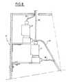
- the 50 pipes(see reference 50 of FIG. 8) leaving the upper clamping block 5b each lead to solenoid valves 47 of the three-way type, known per se. In the normal position, these solenoid valves are closed. It is possible to control their opening and direct the flow of samples during filtering, either to a common evacuation route, or to 50 calibrated blind glass tubes 49, in which the samples accumulate after passing through the filters .
- the connection between each calibrated tube and the corresponding solenoid valvetakes place via pipes 48.
- calibrated tubesallows the clogging tendency control device to be used to also measure the filtered volume for each sample.
- the evacuation routecan be placed under vacuum to continue to aspirate the samples even in the absence of pressure upstream of the aforementioned chamber 27: such a vacuum is effective in eliminating the phenomena of drips.
- the lines 50 and 48are identical to each other and consist of flexible TYGON tubes, the outside diameter of which is 2 mm and the inside diameter of 0.8 mm.
- the fifty solenoid valves 47are arranged in a cabinet 51 (made of sheet metal) as illustrated in FIG. 8.
- the fifty calibrated tubes 49are arranged on two levels, of twenty five tubes each, in another sheet metal cabinet 52.
- the permanent control of the levels of the filtered samples, flowing as the filtering progresses,is carried out using a camera (not shown) which monitors the fifty levels. After digitization, the images of the levels are periodically checked and their progressions are compared with respect to a reference clogging law, using an electronic-computer assembly (not shown) loaded with appropriate software for image analysis.
- each transparent calibrated tube 49The level in the upper part of each transparent calibrated tube 49 is reached in a few minutes.
- the evolution over time of each levelis defined by the position of the level meniscus, which appears as a dark line for the level surveillance camera, which looks at all of the transparent calibrated tubes.
- a mirror 53is placed at 45 ° between the cabinet and the camera, so as to send the image of the calibrated glass tubes 49 towards the latter.
- Fluorescent tubesilluminate tubes calibrated 49 from the rear.
- the bottom of these calibrated tubesis closed by tight plugs 55 each carried by a cam 56, the position of which depends on an electromagnet 57.
- the bottom of the calibrated tubes 49is closed when the cams 56 are raised by the action of a camshaft 58. If the quantity of samples to be filtered is greater than the capacity of each calibrated tube, for example equal to 5 ml, these tubes are opened via the precipitated electromagnet 57, which opens the bottom of the tubes 49: in this case, the filtered samples flow into a collection tank 59 placed under each series of twenty five calibrated tubes and are discharged into a rejection container (not shown).
- dryingcan be useful in order to "fix" the particles on their filter, but also to avoid lateral flows which would contaminate the filtration zones existing on the same filter.
- Dryingeliminates all risk. It is then necessary, as in the previous sequence, to place an empty tank and let the air pass to purge the pipes.
- thiscan advantageously be carried out by alternating inversion of the flow of the samples during filtration.
- a piloting computerit is possible, under the control of a piloting computer, to control the closing of the valve (or valves) concerned, as soon as the clogging has been detected, while also controlling the venting. free from the bin of the sample storage wells, which results in an inversion of the flow of the latter.
- sample inversion cycleswhich are repeated a certain number of times for a relatively short time, for example about a minute
- sample inversion cyclesare normally sufficient to unclog the independent or sealed zone or zones of filtration which is (or are) clogged.
- the filtration device according to the inventioncooperates not only with a storage tank, such as the tank 20 described above comprising fifty storage wells for n sample to be filtered (n being variable from 1 to 50 in the example illustrated), but also with other types of tanks, some with circulation, with heating, etc., while other tanks are essentially tanks allowing the rinsing of the filtration device, which is carried out by TRITON in milk samples, but which may contain color.
- a storage tanksuch as the tank 20 described above comprising fifty storage wells for n sample to be filtered (n being variable from 1 to 50 in the example illustrated)
- other types of tankssome with circulation, with heating, etc.
- other tanksare essentially tanks allowing the rinsing of the filtration device, which is carried out by TRITON in milk samples, but which may contain color.
- Each type of tankis made of duralumin or stainless steel and has an appropriate wall thickness, for example 14 mm, to withstand the pressure. It is the existence of a flange 62 which allows the hooking of the claws 24 of the lower clamping block 5a.
- a pancan be at the base of each tray and allows to equip it with a keying system so that it’s always positioned the same way.
- the containerenters a collar (not shown) placed on the base of the filtration device.
- Additional indexingcan be achieved by coding pins (not shown) prohibiting the placing of a container in a collar intended for another container.
- pinsBy this means, well-identifiable tanks are available which are therefore capable of being placed on the base of the filtration device in the legitimate order of operations corresponding to a given protocol.
- the aforementioned electronic computer assemblyis organized, for example, around a computer system (in particular of the industrial PC type), as already mentioned above.
- the imaging cardallowing the permanent control of the levels in calibrated tubes, contained in the level measurement cabinet 52, is loaded into this computer which also controls a programmable automaton, ensuring the execution of the various operations necessary for operation.
- the filtration device according to the inventioninvolves, for example, lowering the cylinder and opening the solenoid valves, changing the state of the electromagnets, taking into account the signals from the safety systems controlling the position of the filter holder badges tanks, etc ...., as well as the activation of low voltage electrical controls, etc ....
- the imaging card integrated into the computeris connected to the TV camera of the level measurement cabinet and therefore allows the permanent digitization of the image of the fifty levels in the transparent calibrated tubes contained therein and the sending results, tube by tube, to the computer. More precise, the imaging card detects a drop in flow and controls the closing of the solenoid valves arranged on the corresponding pipes.
- sample storage wellscan also be optionally preheated in a water bath with their tanks.
- the volume upstream of the filtersrisks creating a permanent clogging of the latter, when the samples to be filtered are heavily loaded with particles, and the volume downstream does not allow detection of the tendency to clogging when the quantities of filtered liquids are very low (which also corresponds to the case of very loaded samples).
- indexingconsists in identifying the orientation of the filters with respect to the filtration device.
- the direction of filtrationis reversed (from bottom to top ) compared to the conventional direction (from top to bottom), it is possible to easily imagine a device in which the filtration direction is the usual direction.
- a modified device of this kindthere will be at least one perforated joint and, for example, two filters of different porosities as well as the two aforementioned perforated clamping discs, arranged relative to one another as already mentioned above for the device of FIGS. 1 and 2.
- clamping discscan be integrated into two blocks, the upstream block of which will be disposed at the top while the downstream block will be arranged at the bottom, so that the direction of filtration is the conventional direction mentioned above.
- thiscan be a priori arbitrary, provided that there is the possibility of access for the arrivals and departures of the samples to be filtered.
- these blocksmay be constituted by plates, for example secured with a cylindrical structure (enclosure) in a fixed manner, as regards the upper plate, and in a sliding manner as regards the lower plate.
- a clamping actuation devicesuch as a jack (or a lever) arranged at the bottom of the filtration device (the discs could be clamped against the action for safety reasons) springs arranged between the two aforementioned plates).
- the storage wells and the tankwould be replaced by a plurality of metering funnels (cones) each disposed at the upstream (therefore upper) ends, which could be connected, for example, to a perforated plate of the type corresponding to the plates 13a, 13b of FIG. 2) of a plurality of pipes bringing the samples to be filtered to the corresponding perforations of the upper disc, as well as to the filter (s), the perforated seal and the lower disc.
- metering funnelscones
- the enclosure for fixing the aforementioned clamping plates and the connection platecould also be equipped with a sealed closure cover defining a sealed chamber in cooperation with the enclosure and the connection plate for the upstream pipes, in which one could create additional pressure, acting from top to bottom on the samples to be filtered contained in the funnels, so as to accelerate the filtration.
- This operationwould be at low pressure and would remain differentiated from the operation of the device shown in FIGS. 1 and 2, which lends itself to the use of high pressures in chamber 27.
- operation i)consists in detecting a possible reduction in the flow rate of the filtrations for each sample, and this by causing the corresponding filtrates to flow into transparent tubes. and by monitoring the evolution over time of each meniscus of the levels of each of the transparent tubes, with the aid of said image capture device connected to the image digitization device, the aforementioned evolution being compared with the clogging law reference, using said analysis software loaded into said control computer.
- thisessentially consists in making said transparent tubes calibrated, which are closed by removable plugs, the opening of which is controlled when necessary, in particular in the event of evacuation of the filtered samples.
- the direction of filtrationcan be conventional (ie from top to bottom) or reversed (ie from bottom to top) with respect to the usual direction; furthermore, filtration can take place under high pressure or under low pressure.
- a perforated seal 3(delimiting on a filter a plurality of independent and sealed filtration zones corresponding to its perforations) and which is interposed (namely, independent or separate) between two clamping means (in particular constituted by two perforated metal discs forming an integral part of two hollow blocks, the shape of which - substantially frustoconical - makes it possible to reduce the clamping surface of the seal, and therefore of the filter sample support, at relatively small dimensions compatible with rapid microscopic exploration), it is also possible to use a perforated seal which is integrated into one of the two clamping discs, for example the lower disc, and this when only using '' a single filter.
- the sealmay advantageously comprise two pluralities of ribs (not shown) projecting from one of the main faces of the seal, namely from the face which faces towards the clamping disc, the first plurality of which comprise annular sealing ribs each intended to be applied around one of the perforations of the corresponding clamping disc, while the second plurality comprises joining ribs formed between the annular ribs d 'sealing, defining a kind of grid, and intended to fit into complementary grooves of the disc.
- the sealis interposed between the two clamping discs, it can advantageously be equipped with indexing means, for example the same means mentioned above for the badge.
- an upper blockproduced in the form of a fully disposable block, integrating both sample storage wells as well as connecting pipes to the corresponding perforated tightening disc, intended to cooperate with the lower tightened perforated disc (carried by the aforementioned lower block communicating with the suction bowl in which the filtrates are collected).
Landscapes
- Chemical & Material Sciences (AREA)
- Chemical Kinetics & Catalysis (AREA)
- Sampling And Sample Adjustment (AREA)
- Apparatus Associated With Microorganisms And Enzymes (AREA)
- Investigating Or Analysing Biological Materials (AREA)
- Filtering Of Dispersed Particles In Gases (AREA)
- Filtration Of Liquid (AREA)
- Dairy Products (AREA)
Abstract
Description
Translated fromFrenchLa présente invention est relative a un dispositif de filtration simultanée et indépendante, à savoir en parallèle, d'une pluralité d'échantillons fluides, liquides ou gazeux, contenant des particules à filtrer, telles que bactéries, cellules ou autres éléments, notamment contenus dans le lait ou le sang, ce dispositif étant destiné à coopérer avec un dispositif d'observation et de comptage des particules filtrées. Il integre un dispositif de contrôle automatique des niveaux filtres et prévient les risques de colmatage.The present invention relates to a simultaneous and independent filtration device, namely in parallel, of a plurality of fluid, liquid or gaseous samples, containing particles to be filtered, such as bacteria, cells or other elements, in particular contained in milk or blood, this device being intended to cooperate with a device for observation and counting of the filtered particles. It incorporates an automatic filter level control device and prevents the risk of clogging.
Actuellement l'analyse des particules de petite taille et contenues en quantité faible et/ou imprevisible se pratique après filtration préalable sur filtres calibrés (du type connus sous les noms de marques de fabriques NUCLEOPORER, MILLIPORER, etc...). Ces filtres, réalisés par des moyens très évolués, sont coûteux et nécessitent des précautions d'emploi en raison de leur finesse (parfois inférieure à 10 µm) et de leur fragilité.Currently, the analysis of particles of small size and contained in small and / or unpredictable quantities is carried out after prior filtration on calibrated filters (of the type known under the trade names of brands NUCLEOPORER , MILLIPORER , etc.). These filters, produced by very advanced means, are expensive and require precautions for use because of their fineness (sometimes less than 10 μm) and their fragility.
On peut citer comme exemple les analyses du secteur agro-alimentaire (lait, bière, eaux minerales, jus de fruits, viandes, etc..) dans lequels la présence inévitable de bactéries doit être contrôlée.
Dans le cas du lait, la méthode de référence est la méthode de culture sur boîte de Pétri qui exige 24 à 48 heures pour produire un résultat. Il existe d'autres moyens plus rapides fondés, le plus souvent, sur une coloration préalable par un fluorochrome, comme l'Acridine orange. Les appareils se répartissent en deux catégories selon que l'analyse est conservative ou non. Les appareils de la deuxième catégorie mesurent (en continu) les bactéries colorées selon des techniques de flux (flow cytometer) ou de répartition sur des disques ou des tambours.As an example, we can cite analyzes of the agro-food sector (milk, beer, mineral waters, fruit juices, meats, etc.) in which the inevitable presence of bacteria must be checked.
In the case of milk, the reference method is the culture method on a Petri dish which requires 24 to 48 hours to produce a result. There are other faster means based, most often, on a prior staining with a fluorochrome, such as Acridine orange. The devices fall into two categories depending on whether the analysis is conservative or not. The devices of the second category measure (continuously) the colored bacteria according to techniques of flow cytometer or distribution on discs or drums.
Ces méthodes sont à priori simples, mais ne permettent pas de garder l'échantillon à des fins de vérification, ce qui est indispensable en cytologie humaine. Elles ne permettent pas non plus de mesurer correctement des échantillons dans lesquels les bactéries sont en densité très faible (cas de produits élaborés, pharmaceutiques ou alimentaires) et surtout ceux qui renferment des artefacts ou des bactéries sous des formes d'agrégation très variées (bactérie isolée ou colonies de plusieurs milliers de bactéries).These methods are a priori simple, but do not allow the sample to be kept for verification purposes, which is essential in human cytology. They also do not allow correct measurement of samples in which the bacteria are in very low density (case of processed, pharmaceutical or food products) and especially those which contain artefacts or bacteria in very varied forms of aggregation (bacteria isolated or colonies of several thousand bacteria).
L'analyse de l'échantillon filtré, à l'inverse, permet de détecter des bactéries présentes en très faible densité et de respecter la diversité des particules présentes. En revanche, les filtres sont coûteux, les opérations longues et délicates et l'analyse de l'échantillon sous microscope est pénible et lente.Analysis of the filtered sample, on the other hand, makes it possible to detect bacteria present in very low density and to respect the diversity of the particles present. On the other hand, the filters are expensive, the operations long and delicate and the analysis of the sample under a microscope is painful and slow.
L'analyse d'image par ordinateur apporte un début de solution à cette question en automatisant le déplacement de l'échantillon (à l'aide de platines motorisées X-Y et d'un dispositif de focalisation automatique en Z) et en comptant automatiquement les particules.Computer image analysis provides a start to the solution to this question by automating the movement of the sample (using motorized XY stages and an automatic Z-focusing device) and automatically counting the particles. .
Dans le cas du lait, les bactéries sont présentes dans des proportions très variables, ce qui contribue à fixer le prix de ce lait acheté au producteur.In the case of milk, bacteria are present in very variable proportions, which contributes to fixing the price of this milk bought from the producer.
Cette densité est comprise entre 5000 bactéries par millilitre et 5000.10⁴ bactéries par millilitre.This density is between 5000 bacteria per milliliter and 5000.10⁴ bacteria per milliliter.
En supposant que la quantité filtrée soit identique d'un échantillon à l'autre, la quantité de bactéries présentes dans un champ d'observation sera, par exemple, de 1000 pour un lait chargé et de 1 bactérie tous les 10 champs d'observation pour un lait d'excellente qualité. On comprend donc l'intérêt à moduler la quantité de lait à filtrer, ce qui a priori n'est pas possible puisque précisément seule l'analyse permet de connaître ce paramètre.Assuming that the quantity filtered is identical from one sample to another, the quantity of bacteria present in a field of observation will be, for example, 1000 for a loaded milk and of 1 bacterium every 10 fields of observation for excellent quality milk. We therefore understand the interest in modulating the quantity of milk to be filtered, which a priori is not possible since precisely only the analysis makes it possible to know this parameter.
La présente invention s'est donc donné pour but de pourvoir à un dispositif de filtration, basé sur des techniques de filtration actuellement connues, qui permet d'obtenir un débit d'analyse d'échantillons répondant aux nécessités de la pratique.The object of the present invention is therefore to provide a filtration device, based on currently known filtration techniques, which makes it possible to obtain a sample analysis flow rate which meets the requirements of practice.
La présente invention a pour objet un dispositif de filtration d'une pluralité d'échantillons fluides, liquides ou gazeux, contenant des particules à filtrer, telles que bactéries, cellules ou autres éléments, notamment contenues dans le lait ou le sang, comprenant :
- au moins un filtre,
- des moyens de filtration simultanée et indépendantes, sur ce même filtre, desdits échantillons fluides,
- des moyens de filtration forcée des échantillons,
lequel dispositif de filtration est caractérisé en ce que lesdits moyens de la filtration simultanée et indépendante des échantillons fluides comprennent :
- au moins un joint comportant une pluralité de perforations ménagées sur toute son épaisseur,
- un premier et un deuxième moyens de serrage étanche de ce joint et du filtre, présentant les perforations destinées à être alignées avec les perforations du joint et à être mises, avec celles-ci, en communication, à une extrémité amont du joint et par interposition dudit filtre, avec une pluralité d'arrivées indépendantes desdits échantillons fluides à filtrer et , à une extrémité aval dudit joint, avec une pluralité de sorties, également indépendantes, de ces échantillons fluides, lesdits moyens de serrage perforés délimitant sur le filtre, par l'intermédiaire du joint, une pluralité de zones de filtration indépendantes et étanches correspondant auxdites perforations, qui sont destinées à être traversées en parallèle par lesdits échantillons fluides sous l'action desdits moyens de filtration forcée, et
- des moyens d'indexage du (ou des) filtre(s).
- at least one filter,
- means of simultaneous and independent filtration, on this same filter, of said fluid samples,
- means of forced filtration of the samples,
which filtration device is characterized in that said means for the simultaneous and independent filtration of the fluid samples comprise:
- at least one joint comprising a plurality of perforations formed over its entire thickness,
- first and second sealed tightening means of this seal and of the filter, having the perforations intended to be aligned with the perforations of the seal and to be placed, with these, in communication, at an upstream end of the seal and by interposition of said filter, with a plurality of inlets independent of said fluid samples to be filtered and, at a downstream end of said seal, with a plurality of outlets, also independent, of these fluid samples, said perforated clamping means delimiting on the filter, via the seal, a plurality of independent and sealed filtration zones corresponding to said perforations, which are intended to be crossed in parallel by said fluid samples under the action of said forced filtration means, and
- means for indexing the filter (s).
De plus, le dispositif comprend un module de contrôle automatique de la filtration de chacun des échantillons, d'une part, pour connaître le volume réellement filtré et, d'autre part, pour interrompre la filtration en fonction d'un certain degré de colmatage détecté par la diminution du débit des échantillons filtrés.In addition, the device includes an automatic control module for the filtration of each of the samples, on the one hand, to know the volume actually filtered and, on the other hand, to interrupt the filtration according to a certain degree of clogging. detected by the decrease in the flow rate of the filtered samples.
En réalité, l'expérience de la Demanderesse montre que le colmatage progressif du filtre donne une bonne indication de la charge en particules et qu'il suffirait de mesurer en continu le débit d'un échantillon filtré pour évaluer cette charge. De plus, une telle surveillance permet d'arrêter la filtration avant que le colmatage complet n'intervienne, ce qui serait dommageable pour la suite des opérations (notamment pour l'opération de coloration).In reality, the Applicant's experience shows that the gradual clogging of the filter gives a good indication of the charge in particles and that it would suffice to continuously measure the flow rate of a filtered sample to evaluate this charge. In addition, such monitoring makes it possible to stop the filtration before complete clogging occurs, which would be harmful for the rest of the operations (in particular for the coloring operation).
En outre, le dispositif fonctionne avec des filtres traditionnels, mais insérés dans un support (badge) particulier qui assure l'indexation automatique en position, en vue d'une analyse ultérieure. De plus, ce mode de montage du filtre en assure la manipulation aisée et les possibilités d'archivage. On conçoit le gain de place par rapport au montage habituel des filtres entre lame et lamelle, puisque 1 badge sera équivalent à 50 lames, voire plus.In addition, the device operates with traditional filters, but inserted in a particular support (badge) which ensures automatic indexing in position, for later analysis. In addition, this filter mounting mode ensures easy handling and archiving possibilities. We can save space compared to the usual mounting of filters between blade and coverslip, since 1 badge will be equivalent to 50 or more blades.
Le dispositif de contrôle automatique de la filtration et les moyens d'indexation précités seront décrits plus en détail par la suite. Selon une variante préférée de ce mode de réalisation, un deuxième filtre est interposé également entre les extrémités aval des perforations du joint et les sorties indépendantes correspondantes des échantillons, le deuxième filtre ayant une porosité moindre que le filtre disposé en amont, le joint perforé délimitant également sur le deuxième filtre des zones de filtration indépendantes et étanches.The automatic filtration control device and the aforementioned indexing means will be described in more detail below. According to a variant preferred of this embodiment, a second filter is also interposed between the downstream ends of the perforations of the seal and the corresponding independent outputs of the samples, the second filter having a less porosity than the filter placed upstream, the perforated seal also delimiting on the second filter for independent and sealed filtration zones.
Selon une disposition avantageuse de ce mode de réalisation et de cette variante, le(s) filtre(s) avec le joint perforé sont serrés entre un premier et un deuxième disque comportant chacun un nombre de perforations égal à celui du joint, à savoir égal en nombre desdites arrivées et sorties d'échantillons fluides, les perforations du premier disque de serrage recevant les extrémités aval d'une première pluralité de tuyaux, dont les extrémités amont sont en communication avec des puits de stockage des échantillons fluides à filtrer ménagés dans un bac de stockage, tandis que les perforations du deuxième disque de serrage reçoivent les extrémités amont d'une deuxième pluralité de tuyaux, les perforations du joint et lesdites zones de filtration correspondantes du(des) filtre(s) assurant la continuité entre lesdites première et deuxième pluralités de tuyaux, dont la première est destinée à véhiculer vers le(s) filtre(s) les différents échantillons fluides avant filtration, - sous l'action de moyens de refoulement de ces échantillons fluides, contenus dans lesdits puits de stockage , vers les tuyaux correspondants de ladite première pluralité -, alors que la deuxième pluralité de tuyaux est destinée à véhiculer les échantillons fluides après filtration.According to an advantageous arrangement of this embodiment and of this variant, the filter (s) with the perforated seal are clamped between a first and a second disc each comprising a number of perforations equal to that of the seal, namely equal in number of said arrivals and exits of fluid samples, the perforations of the first clamping disc receiving the downstream ends d a first plurality of pipes, the upstream ends of which are in communication with wells for storing the fluid samples to be filtered arranged in a storage tank, while the perforations of the second clamping disc receive the upstream ends of a second plurality of pipes, the perforations of the joint and said corresponding filtration zones of the filter (s) ensuring continuity between said first and second pluralities of pipes, the first of which is intended to convey to the filter (s) the various fluid samples before filtration, - under the action of delivery means for these fluid samples, contained in said storage wells, to the corresponding pipes of said first plurality -, while the second plurality of pipes is intended to convey the fluid samples after filtration.
Selon une modalité préférée de cette disposition, lesdits premier et deuxième disques perforés de serrage étanches entre le(s) filtre(s) et le joint perforé font partie intégrante de blocs creux, qui sont disposés l'un en amont, l'autre en aval, avec les disques se faisant face, et qui sont délimités chacun extérieurement par une enveloppe sensiblement cylindrique, à partir de laquelle ils font saillie vers l'extérieur, et intérieurement par une surface tronconique dont une portion plane correspond à l'emplacement de chaque disque de serrage et une portion oblique correspond à une zone parallèlement à laquelle sont acheminées des portions intermédiaires de ladite première pluralité de tuyaux qui remontent des puits de stockage des échantillons fluides à filtrer ménagés dans ledit bac, pour converger vers les perforations du premier disque, alors que les tuyaux de la deuxième pluralité divergent à partir du deuxième disque, chaque bloc présentant une base ouverte, opposée au disque de serrage correspondant, qui est destinée à être obturée par une plaque amovible appliquée dans un premier siège de chaque bloc et comportant un nombre de perforations qui est égal à celui des perforations du joint, - et donc à celui desdites zones de filtration indépendantes et étanches -, les tuyaux de ladite première pluralité traversant la plaque de fermeture du bloc correspondant et étant reliées à des tubes de prélèvement des échantillons fluides à filtrer, par l'intermédiaire desquels ils communiquent avec les puits de stockage correspondants ménagés dans ledit bac.According to a preferred form of this arrangement, said first and second perforated tight clamping discs between the filter (s) and the perforated seal form an integral part of hollow blocks, which are arranged one upstream, the other in downstream, with the disks facing each other, and which are each delimited externally by a substantially cylindrical envelope, from which they project outwards, and internally by a frustoconical surface of which a flat portion corresponds to the location of each clamping disc and an oblique portion corresponds to a zone parallel to which are conveyed intermediate portions of said first plurality of pipes which rise from the wells for storing the fluid samples to be filtered arranged in said tank, to converge towards the perforations of the first disc, while the pipes of the second plurality diverge from the second disc, each block having an open base, opposite the corresponding tightening disc, which is intended to be closed by a removable plate applied in a first seat of each block and comprising a number of perforations which is equal to that of the perforations of the joint, - and therefore to that of said filtration zones independent and watertight -, the pipes of said first plurality passing through the closing plate of the corresponding block and being connected to tubes for taking fluid samples to be filtered, by means of which they communicate with the corresponding storage wells formed in said tank .
Conformément à cette modalité, au moins les tuyaux de ladite première pluralité sont maintenus fixes les uns par rapport aux autres à l'aide d'une plaquette en résine, -dans laquelle ils sont emprisonnés et qui s'applique de façon étanche dans un deuxième siège du bloc amont, en dessous du disque de serrage correspondant-, et traversent de façon étanche la plaque amovible, le bloc amont étant appliqué, lui aussi de façon étanche, sur le bac de stockage de manière que la plaque amovible, - elle aussi appliquée de façon étanche sur son siège -, délimite conjointement avec l'enveloppe du bloc amont et l'enveloppe du bac de stockage une chambre étanche dans laquelle est injecté un fluide sous pression par un orifice ménagé dans l'enveloppe du bloc, de préférence en aval de la plaque amovible, qui comporte à cet effet une perforation supplémentaire pour le passage du fluide sous pression qui, agissant sur chacun des échantillons fluides à filtrer stockés dans les puits du bac, sont refoulés en parallèle vers le(s) filtres(s) et donc vers ladite deuxième pluralité de tuyaux.According to this modality, at least the pipes of said first plurality are kept fixed with respect to each other using a resin plate, -in which they are trapped and which is applied tightly in a second seat of the upstream block, below the corresponding clamping disc, and pass through the removable plate in a leaktight manner, the upstream block also being applied in a sealed manner on the storage tank so that the removable plate, - also applied tightly to its seat -, together with the envelope of the upstream block and the envelope of the storage tank, delimits a sealed chamber into which a fluid under pressure is injected through an orifice formed in the envelope of the block, preferably downstream of the removable plate, which has for this purpose an additional perforation for the passage of the pressurized fluid which, acting on each of the stored fluid samples to be filtered d in the wells of the tank, are driven back in parallel towards the filter (s) and therefore towards said second plurality of pipes.
Outre les dispositions qui précèdent, l'invention comprend encore d'autres dispositions, qui ressortiront de la description qui va suivre.In addition to the foregoing provisions, the invention also comprises other provisions, which will emerge from the description which follows.
L'invention sera mieux comprise à l'aide du complément de description qui va suivre, qui se réfère aux dessins annexés dans lesquels :
- La figure 1 est une vue en élévation du dispositif selon l'invention ;
- la figure 2 est une vue en élévation, avec coupe partielle, montrant certains détails du dispositif illustré à la figure 1 ;
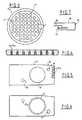
- la figure 3 est une figure de dessus du joint perforé utilisé dans le dispositif des figures 1 et 2 ;
- la figure 4 montre une vue de détail en coupe d'une plaque de fermeture du bloc inférieur illustré à la figure 2 ;
- la figure 5 est une vue de dessus d'un badge porte-filtre utilisé dans le cadre de la présente invention ;
- la figure 6 est une vue de dessous du badge de la figure 5 ;
- la figure 7 est une vue en élévation frontale montrant un détail constructif d'un rail de guidage et de support illustré à la figure 2 et permettant l'introduction du badge précité ;
- la figure 8 est une vue en élévation, avec arrachements, illustrant une armoire à électro-vannes coopérant avec le dispositif de filtration selon l'invention;
- la figure 9 illustre une vue de profil et en élévation latérale d'une armoire de mesure de niveaux coopérant elle aussi avec le dispositif de filtration.
- Figure 1 is an elevational view of the device according to the invention;
- Figure 2 is an elevational view, partly in section, showing certain details of the device illustrated in Figure 1;
- Figure 3 is a top figure of the perforated seal used in the device of Figures 1 and 2;
- Figure 4 shows a detailed sectional view of a closure plate of the lower block illustrated in Figure 2;
- Figure 5 is a top view of a filter holder badge used in the context of the present invention;
- Figure 6 is a bottom view of the badge of Figure 5;
- Figure 7 is a front elevational view showing a constructive detail of a guide rail and support illustrated in Figure 2 and allowing the introduction of the aforementioned badge;
- Figure 8 is an elevational view, with parts broken away, illustrating a cabinet with solenoid valves cooperating with the filtration device according to the invention;
- Figure 9 illustrates a side view and side elevation of a level measurement cabinet also cooperating with the filtration device.
L'utilisation du dispositif de filtration conforme à l'invention, qui est illustré aux figures précitées et qui va être décrit ci-après, requiert la préparation préalable des échantillons à filtrer. Cette préparation comporte trois étapes : distribution des échantillons, ajout de réactifs et de diluant et incubation.The use of the filtration device according to the invention, which is illustrated in the aforementioned figures and which will be described below, requires the prior preparation of the samples to be filtered. This preparation involves three stages: distribution of the samples, addition of reagents and diluent and incubation.
En fait, les échantillons arrivent rarement dans un laboratoire dans des volumes identiques et même si c'était le cas, ces volumes sont normalement trop importants pour l'utilisation dans le dispositif selon l'invention, il faut donc, dans un premier temps, prélever un volume constant et homogène (environ 1 ml) de chaque échantillon à filtrer et le redistribuer dans un bac de stockage, qui sera décrit par la suite.In fact, the samples rarely arrive in a laboratory in identical volumes and even if this were the case, these volumes are normally too large for use in the device according to the invention, it is therefore necessary, firstly, take a constant and homogeneous volume (approximately 1 ml) of each sample to be filtered and redistribute it in a storage tank, which will be described below.
Le passage ultérieur de réactif s'impose pour pouvoir soumettre les échantillons à l'opération d'observation et de comptage bactériens ; évidemment, la variété des réactifs et leur quantité est adaptée à la nature des échantillons.The subsequent passage of reagent is necessary in order to be able to submit the samples to the observation and bacterial counting operation; obviously, the variety of reagents and their quantity is adapted to the nature of the samples.
Le dispositif de filtration 1, selon l'invention, illustré aux figures 1 et 2, comporte deux filtres 2a, 2b, entre lesquels est disposé un joint 3 (cf aussi la la figure 3) qui comporte une pluralité de perforations 4 ménagées sur toute son épaisseur (hauteur). Les filtres s'appliquent de façon étanche contre le joint 3 sous l'action de deux blocs de serrage 5a et 5b, de manière que le joint perforé délimite sur chaque filtre une pluralité de zones de filtration indépendantes et étanches correspondant aux perforations du joint.The filtration device 1, according to the invention, illustrated in FIGS. 1 and 2, comprises two
Le filtre 2b présente une porosité moindre que le filtre 2a.
Chacun des deux blocs de serrage 5a et 5b comporte un disque perforé, 7a et 7b respectivement, pourvu d'un nombre de perforations alignées avec les perforations du joint 3. Chaque disque 7a, 7b fait saillie à partir d'une enveloppe sensiblement cylindrique, 8a et 8b respectivement, délimitant une surface interne tronconique 9, dont la petite base 10 correspond à un disque 7a, 7b tandis que la portion inclinée 11 correspond à une zone parallèlement à laquelle sont acheminées les portions intermédiaires d'une pluralité de tuyaux, tels que les tuyaux 12a et 12b de la figure 2. Les tuyaux 12a convergent vers le disque 7a du bloc 5a, à partir d'une plaque perforée 13a d'obturation étanche du bloc 5a. Cette plaque prend appui sur le siège 14 ménage à l'intérieur de chaque enveloppe 8a, 8b.Each of the two
En ce qui concerne les tuyaux 12b, ceux-ci divergent du disque 7b du bloc 5b vers une plaque perforée 13b, identique à la plaque 13a, qui obture de façon étanche le bloc 5b (cf aussi la figure 4).As regards the pipes 12b, these diverge from the
Le raccordement des tuyaux 12a et 12b aux disques 7a, 7b et aux plaques 13a, 13b, respectivement, se fait à l'aide de raccords rapides.The connection of the
Ces tuyaux sont maintenus en position à l'aide d'une plaquette 15 en résine polymérisee, dans laquelle ils sont emprisonnés et qui s'applique de façon étanche sur un deuxième siège 16 de chaque bloc de serrage, ce siège correspondant à la face interne des disques de serrage 7a, 7b.These pipes are held in position by means of a plate 15 of polymerized resin, in which they are trapped and which is applied in a sealed manner on a
Les extrémités des tuyaux 12a, 12b sont fixées de façon étanche dans les disques et les plaques d'obturation amovibles correspondants.The ends of the
Le bloc de serrage 5a est appliqué de façon étanche (l'étanchéité est assurée par un joint torique 17 fixé dans une rainure 18 ménagée dans l'enveloppe du bloc 5a) sur un bac 20 comportant une pluralité de puits de stockage indépendants 19 destinés à contenir les échantillons à filtrer 46.The
Dans ces puits sont immergés des tubes 21, en acier inoxydable, de prélèvement des échantillons, qui sont reliés aux extrémités inférieures des tuyaux 12a par des raccords rapides, tels que ceux indiqués par la référence 22.In these wells are immersed
Les extrémités inférieures des tubes 21 sont biseautées afin de mieux prélever les échantillons au niveau du fond des puits de stockage sans risquer de se boucher. Leur diamètre extérieur est de 2 mm, alors que le diamètre intérieur est de 0,8 mm.The lower ends of the
Deux griffes de verrouillage 23, sont prévues pour serrer les blocs entre eux, tandis que quatre griffes de verrouillage 24 permettent de serrer le bloc 5a de façon étanche contre le bac 20.Two locking
Des électro-aimants 25 et 26, équipent ces griffes de verrouillage et permettent leur commande d'ouverture.Electromagnets 25 and 26 equip these locking claws and allow their opening control.
Le serrage entre le bloc 5a et le bac 20 permet de créer une chambre étanche 27 délimitée entre la plaque perforée amovible 13a, l'enveloppe 8a du bloc 5a et les puits de stockage 19.The clamping between the
Il est donc possible d'injecter dans la chambre 27 de l'air sous pression par un orifice 28 ménagé dans l'enveloppe 8a du bloc 5a: à cet effet, la plaque perforée amovible 13a comporte une perforation supplémentaire pour le passage de l'air sous pression dans la chambre 27. Il est facile de comprendre que la chambre 27 se comporte, dans ces conditions, comme un système de cloche à pression qui, sous l'action de la pression de l'air exercée sur les échantillons à filtrer, stockés dans les puits du bac, permet leur renfoulement, en parallèle, vers les filtres 2a et 2b, à travers les tubes de prélèvement 21, les tuyaux 12a et le joint d'étanchéité 3.It is therefore possible to inject pressurized air into the chamber 27 through an
Le filtrat passe ensuite dans les tuyaux 12b.The filtrate then passes through the pipes 12b.
Il est donc clair que dans le dispositif illustré aux figures 1 et 2 la filtration des échantillons a lieu en sens inversé (du bas vers le haut) par rapport au sens classique (du haut vers le bas).It is therefore clear that in the device illustrated in FIGS. 1 and 2, the filtration of the samples takes place in the reverse direction (from the bottom to the top) with respect to the conventional direction (from the top to the bottom).
Pour permettre de manipuler, sans risque de les abîmer, tout en permettant de les indexer, les filtres 2a, 2b, ceux-ci sont collés sous la face férieure d'un badge porte-filtre 29, illustré aux figures 5 et 6, sur une zone annulaire indiquée par la référence 30 délimitant une ouverture circulaire 31, dans laquelle pénétrent les disques 7a, 7b. Ce badge est dessiné de telle sorte qu'il ne puisse se placer à l'envers.To allow handling, without risk of damaging them, while allowing them to be indexed, the
Chaque badge porte-filtre est destiné à être introduit dans un rail métallique 32 de guidage et de support (du badge) illustré aux figures 2 et 7. L'introduction de chaque badge dans le rail correspondant est facilitée par la présence d'un biseau 36.Each filter holder badge is intended to be inserted into a metal guide and support rail 32 (of the badge) illustrated in FIGS. 2 and 7. The introduction of each badge into the corresponding rail is facilitated by the presence of a
On peut remarquer la grande ouverture centrale 33, correspondant à l'ouverture 31 du badge, ainsi que la présence d'encoches 34 ménagées dans deux épaulements latéraux 35 du rail 32. Chaque badge est, en fait, glissé dans les encoches 34. Pour permettre, l'introduction correcte du badge dans le rail on peut utiliser un systeme détrompeur (non représenté aux figures). Les rails 32 ainsi équipés sont enfilés dans les disques 7a, 7b des blocs 5a, 5b, lorsque ceux-ci sont écartés entre eux. De cette manière les filtres 2a, 2b peuvent être serrés entre chaque disque des blocs de serrage et le joint d'étanchéité 3.We can notice the large
Il est facile de vérifier que le dessin des rails est conçu pour qu'il n'y ait aucun risque d'accrochage avec une partie dure susceptible de perforer les filtres, qui sont fragiles.It is easy to verify that the drawing of the rails is designed so that there is no risk of snagging with a hard part liable to perforate the filters, which are fragile.
Le badge 29 peut avantageusement coopérer avec un système détrompeur soit en ménageant sur le badge des perforations ou des encoches de détrompage 37b, destinées à coopérer avec des saillies de détrompage portées par le système détrompeur (non représenté) précité, disposé dans le rail, pour permettre l'introduction du badge dans ce dernier et connaître la nature du filtre, évitant ainsi des erreurs.The
De façon simplifiée, l'indexation peut être obtenue en découpant ou en perforant la périphérie du filtre (la même forme existe alors en mâle sur un microscope d'analyse du filtre).In a simplified way, indexing can be obtained by cutting or perforating the periphery of the filter (the same shape then exists in male on a microscope for analyzing the filter).
Il est possible de coder binairement plus de dix types de filtres à l'aide de découpes ménagées dans chaque filtre.It is possible to binarily code more than ten types of filters using cutouts in each filter.
L'indexation en position du badge est réalisée à l'aide de plots de centrage (non représentés) qui sont portés par le rail 32 et qui viennent se placer dans deux trous de centrage correspondants, 37 et 37a du badge 29.Indexing of the badge position is carried out using centering studs (not shown) which are carried by the
Le badge porte-filtre conforme à l'invention confère au dispositif de filtration les avantages suivants (en coopération avec d'autres éléments qui seront évoqués plus loin), qui sont définis par la possibilité de :
- 1) effectuer l'analyse des échantillons dans un autre poste de travail,
- 2) reprendre le filtre pour réexaminer les objets (bactéries, etc..), dont il est porteur, après coloration appropriée,
- 3) ajouter des produits spéciaux sur le filtre pour obtenir une réaction spécifique d'affinité entre le filtre et les objets qu'il porte,
- 4) recueillir individuellement, les objets précités soit à l'aide de micro-pipettes (d'un diamètre d'aspiration approximativement de l'ordre de 5 µm) ou de micro-adhésifs, etc...
- 5) transférer sur un adhésif transparent, à l'aide d'un "contre-badge" de support de cet adhésif, et ce par calquage par pression, les objets du filtre porté par le badge (à savoir, les informations utiles), tout en annulant les éventuelles déformations du filtre (à structure micro-perforée, donc très délicate) et en obtenant aussi un contraste extraordinaire, la fluorescence du fond défini par la surface d'observation du filtre étant parfois gênante.
- 1) perform the analysis of the samples in another work station,
- 2) take the filter back to re-examine the objects (bacteria, etc.), which it carries, after appropriate coloring,
- 3) add special products to the filter to obtain a specific affinity reaction between the filter and the objects it carries,
- 4) collect the aforementioned objects individually either with the aid of micro-pipettes (with a suction diameter approximately of the order of 5 μm) or micro-adhesives, etc.
- 5) transfer to a transparent adhesive, using a "back-badge" for supporting this adhesive, and this by pressure tracing, the objects of the filter carried by the badge (namely, the useful information), while canceling any deformations of the filter (with micro-perforated structure, therefore very delicate) and also obtaining an extraordinary contrast, the fluorescence of the background defined by the observation surface of the filter being sometimes troublesome.
De cette manière, les procédés classiques d'analyse d'échantillons notamment biologiques sont enrichis par les opérations évoquées sous 1) à 5).In this way, the conventional methods for analyzing samples, in particular biological samples, are enriched by the operations mentioned under 1) to 5).
L'utilisation de deux filtres permet d'appliquer le principe du double filtrage, à savoir d'arrêter par le premier filtre 2a, les particules les plus grosses, susceptibles de gêner l'analyse ultérieure sur le filtre plus fin 2b.The use of two filters makes it possible to apply the principle of double filtering, namely to stop by the first filter 2a, the coarsest particles, liable to interfere with the subsequent analysis on the
Il est aussi clair que le dispositif de filtration peut fonctionner avec un seul filtre ou, moyennant de légères modifications, avec 3, 4 ou 5 filtres et même plus.It is also clear that the filtration device can operate with a single filter or, with slight modifications, with 3, 4 or 5 filters and even more.
Bien entendu, lorsqu'on veut effectuer un rinçage des canalisations et du joint, aucun filtre n'est nécessaire : dans ce cas, il est prévu d'introduire donc des badges sans filtre. La présence d'un filtre peut être validée par un micro-rupteur, chaque badge étant retenu dans le rail correspondant par un portillon (non représentés); c'est l'action conjuguée du micro-rupteur et du portillon qui commande le fonctionnement du dispositif de filtration, un voyant lumineux s'allumant lorsque les blocages de serrage du dispositif sont autorisés à être fermés.Of course, when you want to rinse the pipes and the seal, no filter is necessary: in this case, it is planned to introduce badges without filter. The presence of a filter can be validated by a micro-switch, each badge being retained in the corresponding rail by a door (not shown); it is the combined action of the micro-switch and the gate that controls the operation of the filtration device, an indicator light coming on when the device's tightening locks are authorized to be closed.
En ce qui concerne le joint d'étanchéité, celui-ci est réalisé en élastomère de silicone et est calculé pour s'écraser légèrement tout en se dilatant radialement de manière à contribuer au renforcement de la tension des filtres.Regarding the seal, it is made of silicone elastomer and is calculated to be slightly crushed while expanding radially so as to contribute to the reinforcement of the tension of the filters.
Dans certaines conditions une plaque microperforée (de type connu des techniciens en la matière) vient se placer en aval entre le filtre et les disques des blocs de serrage.Under certain conditions, a microperforated plate (of a type known to technicians in the field) is placed downstream between the filter and the discs of the clamping blocks.
Les perforations du joint (au nombre de 50 dans l'exemple 35 illustré) sont en parfait alignement avec les perforations des disques de serrage 7a, 7b des blocs 5a, 5b.The perforations of the joint (50 in number in the example 35 illustrated) are in perfect alignment with the perforations of the clamping
Le joint 3 est en liaison souple avec ces blocs.The seal 3 is in flexible connection with these blocks.
L'écartement entre le joint et les blocs est obtenu à l'aide de ressorts (non représentés) qui permettent de définir deux fentes d'accès par lesquelles sont introduits les badges porte-filtre montés dans les rails correspondants (cf fig. 1).The spacing between the seal and the blocks is obtained by means of springs (not shown) which make it possible to define two access slots through which are inserted the filter holder badges mounted in the corresponding rails (see fig. 1) .
Le serrage des filtres entre le joint en élastomère de silicone 3 et les disques 7a, 7b des blocs 5a, 5b, se fait à l'aide d'un vérin pneumatique 38 supporté par une plaque supérieure 39 par l'intermédiaire d'une entretoise 45 fixée à cette plaque, qui est reliée à un socle 40 par des colonnes de guidage 41 en acier permettant le coulissement des pièces mobiles avec une grande précision. Le long de ces colonnes coulisse une plaque 42 qui est reliée à la tige 44 du vérin 38. C'est cette tige qui provoque la descente de la plaque coulissante 42, qui vient en appui sur des piliers 43 solidaires du bloc de serrage supérieur 5b, faisant ainsi descendre ce dernier (cf la figure 1).The filters are tightened between the silicone elastomer seal 3 and the
Etant donné que le bloc 5b est solidarisé avec le bloc inférieur 5a, lors de la de2scente du vérin 38, le bloc inférieur 5a est mis en contact avec le bac 20, réalisant ainsi l'étanchéité globale du système, premièrement, entre le bac et le bloc inférieur grâce à la présence du joint torique 17 et, deuxièmement, entre les blocs de serrage et les filtres, d'une part, et les filtres et le joint, d'autre part. Il est facile de comprendre que le caractère global du serrage des filtres assure avec un mouvement le serrage de ce dernier et l'étanchéité de mise en pression du bac. Il est facile de comprendre que la qualité de surface des disques de serrage des blocs 5a, 5b est essentielle pour l'étanchéité.Since the
Comme le montre la figure 1, le bac est placé sur le socle 40, entre les colonnes de guidage 41, qui forment une sorte de cage.As shown in Figure 1, the tray is placed on the
En ce qui concerne le vérin 38, celui-ci est un vérin pneumatique fonctionnant avec une pression de 5 à 7 bars, à l'air lubrifié. Il est du type commandé par une vanne à trois positions, ce qui permet de le placer en position haute, basse ou intermédiaire.As regards the
Ce vérin permet d'appliquer une force d'environ 200 kg, ce qui assure la descente de l'ensemble des deux blocs de serrage 5a, 5b et l'encliquetage du bloc inférieur 5a sur le bac 20.This jack makes it possible to apply a force of approximately 200 kg, which ensures the descent of the assembly of the two
Bien entendu, le vérin d'actionnement peut être disposé au-dessous du bac 20, sans que pour autant le fonctionnement du dispositif soit altéré.Of course, the actuating cylinder can be arranged below the
C'est l'enveloppe des blocs de serrage, réalisée en acier inoxydable ou en matériau plus léger, tel que duralumin, qui encaisse les efforts de compression créés par le vérin ou ceux encore plus grands réalisés lors de la mise en pression de la chambre précitée (en ce qui concerne les deux blocs de serrage, ils sont sensiblement identiques entre eux, mise à part la présence de l'arrivée 28 d'entrée d'air sous pression pour le seul bloc inférieur).It is the envelope of the clamping blocks, made of stainless steel or of a lighter material, such as duralumin, which collects the compression forces created by the jack or those even greater made during the pressurization of the chamber. above (as regards the two clamping blocks, they are substantially identical to each other, apart from the presence of the
La mise en pression de la chambre 27, qui est évidemment précédée par la descente du vérin 38, a lieu à l'aide d'air comprimé envoyé à une pression réglable de 1 à 7 bars (sans pour autant exclure l'utilisation d'une pression plus élevée) par l'orifice 28.The pressurization of the chamber 27, which is obviously preceded by the descent of the
Le volume réduit du bac 20 et l'emploi de matériaux non cassants, conjointement à l'emploi d'un joint d'étanchéité torique, éliminent les risques liés à la pression bien que, en cas de besoin, il serait facile d'entourer la cage (constituée par les colonnes de guidage 41) par un caisson métallique de protection.The reduced volume of
Sous l'action de la pression, les échantillons 46, contenus dans des puits de stockage 19 du bac 20, sont chassés en parallèle, à savoir de façon indépendante, dans les 50 tubes de prélèvement 21 (ceci impose, évidemment, que les canalisations disposées en aval soient ouvertes).Under the action of pressure, the
Les échantillons passent ensuite au travers de zones de filtration indépendantes délimitées, sur chaque filtre, par le joint 3 et les disques de serrage 7a, 7b.The samples then pass through independent filtration zones delimited, on each filter, by the seal 3 and the
L'étanchéité est telle qu'il ne peut y avoir d'échange et de pollution d'une zone de filtration aux zones voisines définies sur un même filtre.The tightness is such that there can be no exchange and pollution from a filtration zone to the neighboring zones defined on the same filter.
Les échantillons ainsi filtrés s'évacuent par les canalisations reliées aux tuyaux 12b du bloc supérieur.The samples thus filtered are discharged through the pipes connected to the pipes 12b of the upper block.
En ce qui concerne l'actionnement des électroaimants de commande de l'ouverture des griffes de verrouillage précitées, il y a lieu de noter qu'il doit être effectué après la remise en pression du vérin et la vidange de l'air de mise sous pression du bac.With regard to the actuation of the electromagnets for controlling the opening of the abovementioned locking claws, it should be noted that it must be carried out after the cylinder has been put back under pressure and the supply air has been drained tank pressure.
Bien entendu, des dispositifs de sécurité, connus des techniciens en la matière, sont à prévoir pour vérifier les mauvais fonctionnements des électro-aimants et des griffes de verrouillage, afin d'éviter que le bac soit entraîné intempestivement vers le haut par la remontée du vérin.Of course, safety devices, known to technicians in the field, are to be provided to check the malfunctions of the electromagnets and the locking claws, in order to prevent the tray from being inadvertently drawn upwards by the ascent of the cylinder.
En ce qui concerne la destination immédiate du filtrat, qui sot des filtres 2a, 2b et qui parcourt les tuyaux 12b sortant du bloc supérieur de serrage 5b, celle-ci se réduit à une simple évacuation.Regarding the immediate destination of the filtrate, which is
Toutefois, dans le cadre de la présente invention, il est prévu d'effectuer un contrôle de la tendance au colmatage de chaque zone de filtration des filtres (ainsi que des canalisations) par les particules contenues dans les échantillons, au cours du filtrage. La méthode employée est basée sur la détection d'une diminution du débit de filtration.However, in the context of the present invention, provision is made for carrying out a trend check. the clogging of each filtration zone of the filters (as well as the pipes) by the particles contained in the samples, during filtration. The method used is based on the detection of a decrease in the filtration rate.
Ce contrôle s'impose parce qu'un filtre colmaté ne se prêterait pas aux opérations de traitement préalable pour l'observation et le comptage bactériens suivant la filtration.This control is necessary because a clogged filter would not lend itself to prior treatment operations for observation and bacterial counting after filtration.
A cet effet, les 50 canalisations (cf.référence 50 de la figure 8) sortant du bloc de serrage supérieur 5b débouchent chacune sur des électro-vannes 47 du type à trois voies, connu en soi. En position normale, ces électrovannes sont fermées. Il est possible de commander leur ouverture et de diriger le flux des échantillons en cours de filtrage, soit vers une voie commune d'évacuation, soit vers 50 tubes calibrés borgnes en verre 49, dans lesquels les échantillons s'accumulent après avoir traversé les filtres. La liaison entre chaque tube calibré et l'électrovanne correspondante se fait par l'intermédiaire de canalisations 48.To this end, the 50 pipes (see
L'utilisation des tubes calibrés permet d'utiliser le dispositif de contrôle de la tendance au colmatage pour effectuer aussi une mesure du volume filtré pour chaque échantillon.The use of calibrated tubes allows the clogging tendency control device to be used to also measure the filtered volume for each sample.
La voie d'évacuation peut être mise en dépression pour continuer à aspirer les échantillons même en l'absence de pression en amont de la chambre 27 préci-tée : une telle dépression est efficace pour éliminer les phénomènes de gouttes pendantes.The evacuation route can be placed under vacuum to continue to aspirate the samples even in the absence of pressure upstream of the aforementioned chamber 27: such a vacuum is effective in eliminating the phenomena of drips.
Les canalisations 50 et 48 sont identiques entre elles et sont constituées par des tubes souples en TYGON, dont le diamètre extérieur est de 2 mm et le diamètre intérieur de 0,8 mm.The
Les cinquante électrovannes 47 sont disposées dans une armoire 51 (réalisée en tôle) comme illustré à la figure 8. De même, les cinquante tubes calibrés 49 sont disposés sur deux niveaux, de vingt cinq tubes chacun, dans une autre armoire en tôle 52.The fifty
Le contrôle permanent des niveaux des échantillons filtrés, s'écoulant au fur et à mesure du filtrage, est effectué à l'aide d'une caméra de prises de vues (non représentée) qui surveille les cinquante niveaux. Après numérisation, les images des niveaux sont contrôlées périodiquement et leurs progressions sont comparées par rapport à une loi de colmatage de référence, et ce à l'aide d'un ensemble électronique-informatique (non représenté) chargé d'un logiciel approprié d'analyse d'images.The permanent control of the levels of the filtered samples, flowing as the filtering progresses, is carried out using a camera (not shown) which monitors the fifty levels. After digitization, the images of the levels are periodically checked and their progressions are compared with respect to a reference clogging law, using an electronic-computer assembly (not shown) loaded with appropriate software for image analysis.
Le niveau en partie haute de chaque tube calibré transparent 49 est atteint en quelques minutes. L'évolution dans le temps de chaque niveau est définie par la position du ménisque de niveau, qui apparaît comme un trait sombre pour la caméra de surveillance des niveaux, qui regarde la totalité des tubes calibrés transparents.The level in the upper part of each transparent calibrated
Afin de réduire l'encombrement, un miroir 53 est placé à 45° entre l'armoire et la caméra, de façon à renvoyer l'image des tubes calibrés en verre 49 vers cette dernière. Des tubes fluorescents éclairent des tubes calibrés 49 par l'arrière. Le fond de ces tubes calibrés est obturé par des bouchons étanches 55 portés chacun par une came 56, dont la position dépend d'un électro-aimant 57.In order to reduce the bulk, a
Le fond des tubes calibrés 49 est obturé lorsque les cames 56 sont relevées par l'action d'un arbre à came 58. Si la quantité d'échantillons à filtrer est plus importante que la contenance de chaque tube calibré, par exemple égale à 5 ml, ces tubes sont ouvert par l'intermédiaire de l'électro-aimant 57 précipité, qui ouvre le fond des tubes 49 : dans ce cas, les échantillons filtrés s'écoulent dans un bac de recueil 59 placé sous chaque série de vingt cinq tubes calibrés et sont évacués dans un récipient de rejet (non représenté).The bottom of the calibrated
Lorsque le système détecte une tendance au colmatage sur un tube, l'électrovanne du tube correspondant est fermée et le liquide contenu dans le puits ne passe plus, ce qui n'empêche pas la filtration de se poursuivre dans les autres tubes, qui à leur tour seront fermés, si besoin est.When the system detects a clogging tendency on one tube, the solenoid valve of the corresponding tube is closed and the liquid contained in the well no longer passes, which does not prevent filtration from continuing in the other tubes, which at their tower will be closed, if necessary.
Dans le cas de liquides qui ne provoquent pas le colmatage des filtres ou pour lesquels il n'est pas nécessaire de pousser la filtration très loin (car il existe une densité de particules ou de cellules élevée), le suivi de la filtration n'est pas utile. Il suffit alors d'appliquer la pression pendant un temps déterminé, de telle sorte qu'aucun puits n'arrive à être vidé complètement. En effet, si tel était le cas, il se produirait une chute de pression sensible et la filtration serait ralentie.In the case of liquids which do not cause clogging of the filters or for which it is not necessary to push the filtration very far (because there is a high density of particles or cells), the monitoring of the filtration is not not useful. It then suffices to apply the pressure for a determined time, so that no well can be emptied completely. Indeed, if this were the case, a significant pressure drop would occur and filtration would be slowed down.
Pour passer les échantillons suivants, sans rompre l'étanchéité de la filtration, la procédure est la suivante :
- 1) on fait tomber la pression dans le bac (par ouverture d' une vanne),
- 2) on descend le vérin 38,
- 3) on ouvre les griffes 23,
- 4) on remonte le vérin 38,
- 5) on place le bac suivant, par exemple un bac de rinçage, à la place du bac de stockage d'échantillons,
- 6) on redescend le vérin et on remet en pression.
- 1) the pressure is dropped in the tank (by opening a valve),
- 2) the
cylinder 38 is lowered, - 3) the
claws 23 are opened, - 4) the
cylinder 38 is reassembled, - 5) the following tank is placed, for example a rinsing tank, in place of the sample storage tank,
- 6) the cylinder is lowered again and pressure is restored.
Dans cette séquence, les filtres sont toujours restés en étanchéité. En principe, aucun liquide ne s'écoulera, ni à partir des tubes de prélèvement (reflux), ni en aval, puisque toutes les électrovannes sont fermées depuis la dernière mise en pression.In this sequence, the filters have always remained watertight. In principle, no liquid will flow either from the sampling tubes (reflux) or downstream, since all the solenoid valves have been closed since the last pressurization.
Après leur ouverture globale, le(s) liquide(s) nouveau(x) viendra(ont) progressivement remplacer les échantillons liquides qui étaient restés dans les tubulures. A priori, si les fermetures des électrovannes avaient été déclenchées par les mêmes paramètres de niveau et/ou de colmatage, le passage des liquides suivants devra se faire de façon identique, selon les tubes.After their global opening, the new liquid (s) will gradually replace the liquid samples that remained in the tubing. A priori, if the solenoid valve closings were triggered by the same level and / or clogging parameters, the passage of the following liquids should be done identically, depending on the tubes.
En fin d'opération, un séchage peut être utile afin de "fixer" les particules sur leur filtre, mais aussi d'éviter des écoulements latéraux qui contamineraient les zones de filtration existant sur un même filtre.At the end of the operation, drying can be useful in order to "fix" the particles on their filter, but also to avoid lateral flows which would contaminate the filtration zones existing on the same filter.
En effet, les essais montrent que, pou: des cellules ou des bactéries, après un passage en pression, l'attachement des particules sur le filtre est suffisamment fort pour que le risque soit nul. Pour d'autres particules, le risque peut exister : deux solutions existent dans le système :
- 1) les électrovannes fermées empêchent le reflux pour les tubes en aval du dernier filtre
- 2) la filtration en sens inversé (du bas vers le haut) par rapport au sens classique (du haut vers le bas) fait que les liquides présents dans les tubes en amont des filtres s'écoulent dans le bac.
- 1) the closed solenoid valves prevent backflow for the tubes downstream of the last filter
- 2) filtration in the reverse direction (from the bottom to the top) compared to the conventional direction (from the top to the bottom) causes the liquids present in the tubes upstream of the filters to flow into the tank.
Le séchage élimine tout risque. Il faut alors, comme lors de la séquence précédente, placer un bac vide et laisser passer l'air pour purger les canalisations.Drying eliminates all risk. It is then necessary, as in the previous sequence, to place an empty tank and let the air pass to purge the pipes.
Après la descente du vérin, toutes les griffes 23 et 24 seront dégagées et, lors de la remontée du vérin, les fentes d'accès au joint 3 seront ouvertes et les badges pourront être retirés.After the lowering of the jack, all the
En ce qui concerne le décolmatage du filtre, celui-ci peut être avantageusement effectué par inversion alternée de l'écoulement des échantillons en cours de filtration. A cet effet, on peut, sous contrôle d'un ordinateur de pilotage, commander la fermeture de la vanne (ou des vannes) concernée(ées), dès que le colmatage a été détecté, tout en commandant également la mise à l'air libre du bac des puits de stockage des échantillons, ce qui entraîne une inversion du flux de ces derniers.With regard to unclogging the filter, this can advantageously be carried out by alternating inversion of the flow of the samples during filtration. For this purpose, it is possible, under the control of a piloting computer, to control the closing of the valve (or valves) concerned, as soon as the clogging has been detected, while also controlling the venting. free from the bin of the sample storage wells, which results in an inversion of the flow of the latter.
Quelques dizaines de cycles d'inversion de l'échantillon (qui est répétée un certain nombre de fois pendant un temps relativement court, par exemple une minute environ) sont suffisantes normalement pour décolmater la zone ou les zones de filtration, indépendantes et étanches, qui est (ou qui sont) colmatée(ées).A few tens of sample inversion cycles (which are repeated a certain number of times for a relatively short time, for example about a minute) are normally sufficient to unclog the independent or sealed zone or zones of filtration which is (or are) clogged.
Toutefois, en procédant de cette manière (à savoir , en mettant en oeuvre une sorte de fonctionnement en "push-pull"), il faut prendre des mesures appropriées pour que la (les) quantité(s) d'échantillon(s) soi(en)t le plus petite(s) possible, juste suffisante(s) pour un décolmatage efficace : à cet effet, il convient d'utiliser des capillaires (constituant les tubes de prélèvement et les tuyaux amont et aval évoqués plus haut) pas trop souples.However, in proceeding in this manner (ie, implementing some sort of push-pull operation), appropriate measures must be taken so that the amount (s) of sample (s) is (en) t as small as possible, just sufficient for effective unclogging: for this purpose, it is advisable to use capillaries (constituting the sampling tubes and the upstream and downstream pipes mentioned above) no too flexible.
Le dispositif de filtration selon l'invention coopère non seulement avec un bac de stockage, tel que le bac 20 décrit plus haut comprenant cinquante puits de stockage pour n échantillon à filtrer (n étant variable de 1 à 50 dans l'exemple illustré), mais aussi avec d'autres types de bacs, dont certains à circulation, avec chauffage, etc....., tandis que d'autres bacs sont essentiellement des bacs permettant le rinçage du dispositif de filtration, qui est effectué par du TRITON dans le cas d'échantillons de lait, mais qui peuvent contenir du colorant.The filtration device according to the invention cooperates not only with a storage tank, such as the
Chaque type de bac est réalisé en duralumin ou en inox et présente une épaisseur de paroi appropriée, par exemple de 14 mm, pour résister à la pression. C'est l'existence d'un rebord 62 qui permet l'accrochage des griffes 24 du bloc de serrage inférieur 5a.Each type of tank is made of duralumin or stainless steel and has an appropriate wall thickness, for example 14 mm, to withstand the pressure. It is the existence of a
Un pan (non représenté) peut être à la base de chaque bac et permet de l'équiper d'un système détrompeur afin qu'il soit toujours positionné de la même façon. A cet effet, du bac pénètre dans un collier (non représenté) placé sur le socle du dispositif de filtration.A pan (not shown) can be at the base of each tray and allows to equip it with a keying system so that it’s always positioned the same way. For this purpose, the container enters a collar (not shown) placed on the base of the filtration device.
Un indexage supplémentaire peut être réalisé par un codage d'ergots (non représentés) interdisant de placer un bac dans un collier destiné à un autre bac. Par ce moyen, on dispose de bacs bien identifiables et qui sont donc susceptibles d'être placés sur le socle du dispositif de filtration dans l'ordre légitime des opérations correspondant à un protocole donné. En disposant les ergots précités de façon oblique, on peut aussi les utiliser pour la reconnaissance automatique (à savoir, présence, absence et type) à l'aide de microcontacts.Additional indexing can be achieved by coding pins (not shown) prohibiting the placing of a container in a collar intended for another container. By this means, well-identifiable tanks are available which are therefore capable of being placed on the base of the filtration device in the legitimate order of operations corresponding to a given protocol. By placing the above pins obliquely, they can also be used for automatic recognition (ie, presence, absence and type) using microswitches.
L'ensemble électronique informatique précité est organisé, par exemple, autour d'un système informatique, (notamment du type PC industriel), comme déjà évoqué plus haut.The aforementioned electronic computer assembly is organized, for example, around a computer system (in particular of the industrial PC type), as already mentioned above.
La carte d'imagerie permettant le contrôle permanent des niveaux dans des tubes calibrés, contenus dans l'armoire de mesure des niveaux 52, est chargée dans cet ordinateur qui pilote aussi un automate programmable, assurant l'exécution des différentes opérations nécessaires pour le fonctionnement du dispositif de filtration selon l'invention ; il s'agit, par exemple, de la descente du vérin et de l'ouverture des électrovannes, du changement d'état des électro-aimants, de la prise en compte des signaux des systèmes de sécurité contrôlant la position des badges porte-filtre des bacs, etc...., ainsi que de l'activation des commandes électriques en basse tension, etc....The imaging card allowing the permanent control of the levels in calibrated tubes, contained in the
La carte d'imagerie intégrée à l'ordinateur est reliée à la caméra TV de l'armoire de mesure de niveaux et permet donc la numérisation permanente de l'image des cinquante niveaux dans les tubes calibrés transparents qui y sont contenus et l'envoi des résultats, tube par tube, à l'ordinateur. De façon plus précise, la carte d'imagerie détecte une baisse de débit et commande la fermeture des électrovannes disposées sur les canalisations correspondantes.The imaging card integrated into the computer is connected to the TV camera of the level measurement cabinet and therefore allows the permanent digitization of the image of the fifty levels in the transparent calibrated tubes contained therein and the sending results, tube by tube, to the computer. More precise, the imaging card detects a drop in flow and controls the closing of the solenoid valves arranged on the corresponding pipes.
L'ordinateur a donc trois fonctions principales:
- gestion du dispositif de filtration dans son ensemble et en particulier,du système d'imagerie et des automatismes.
- interface avec l'utilisateur,
- traitement des résultats (qui sont communiqués à une imprimante).
- management of the filtration system as a whole and in particular, of the imaging system and automatisms.
- user interface,
- processing of results (which are communicated to a printer).
Le nombre de bactéries par ml peut être détermine par l'ordinateur en fonction :
- . du volume d'échantillon prélevé,
- . des proportions des différents additifs utilises lors de la préparation préalable de chaque échantillon,
- . du volume d'échantillon filtré,
- . du nombre de bactéries trouvées lors de l'observation et le comptage bactériens d'un filtre chargé en bactéries à l'aide du dispositif de filtration selon l'invention.
- . the volume of sample taken,
- . proportions of the various additives used during the prior preparation of each sample,
- . the volume of sample filtered,
- . the number of bacteria found during the observation and bacterial count of a filter loaded with bacteria using the filtration device according to the invention.
En ce qui concerne le dispositif d'observation et de comptage, celui-ci comporte des objectifs et peut utiliser une platine, telle que celle qui fait l'objet d'une Demande de Brevet co-pendante déposée conjointement par la Demanderesse.As far as the observation and counting device is concerned, it has objectives and can use a stage, such as that which is the subject of a co-pending Patent Application filed jointly by the Applicant.
Au demeurant, on peut imaginer une autre structure pour les blocs de serrage desquels font partie intégrante les disques perforés 7a, 7b, de serrage étanche des filtres 2a 2b en coopération avec le joint perforé 3.Besides, one can imagine another structure for the clamping blocks of which the perforated discs are an integral part. 7a, 7b, for tightly tightening the
En outre, il est possible de prévoir un dispositif de chauffage des blocs de serrage permettant de garder les filtres à une température de l'ordre de 40°C, ce qui améliore la filtration des échantillons légèrement visqueux.In addition, it is possible to provide a heating device for the clamping blocks making it possible to keep the filters at a temperature of the order of 40 ° C., which improves the filtration of slightly viscous samples.
Les puits de stockage des échantillons peuvent également être éventuellement préchauffés au bain-marie avec leurs bacs.The sample storage wells can also be optionally preheated in a water bath with their tanks.
De plus, il y a lieu de souligner qu'il faut prévoir une pluralité de bacs permettant la coloration des filtres, après la filtration, ainsi que les différentes étapes de rinçage et de désinfection (une désinfection s'impose en fait pour éviter la contamination due au passage des tubes - ou aiguilles - de prélèvement d'un bac à un autre, en sorte qu'il est bien que le rinçage soit effectué avec un liquide désinfectant).In addition, it should be emphasized that there must be a plurality of tanks allowing the coloring of the filters, after filtration, as well as the different stages of rinsing and disinfection (disinfection is essential in fact to avoid contamination due to the passage of the tubes - or needles - of collection from one tank to another, so that it is good that the rinsing is carried out with a disinfectant liquid).
Il est en outre possible de prévoir l'introduction automatique de ces bacs, ainsi que des bacs précédemment décrits, sous les blocs de serrage permettant la filtration des échantillons, et ce afin de diminuer le temps requis par l'exécution des opérations manuelles.It is also possible to provide for the automatic introduction of these tanks, as well as the tanks described above, under the clamping blocks allowing the filtration of the samples, in order to reduce the time required for the execution of manual operations.
En ce qui concerne le chauffage des blocs de filtration avant que la filtration ait lieu, celui-ci peut être réalisé de deux façons :
- par passage de TRITON, éventuellement dilué, chauffé à 50°C, juste avant la filtration, comme préconisé par la méthode DEFT, ou
- par chauffage direct de la zone du dispositif contenant les filtres, sous contrôle d'un thermostat.
- by passing TRITON, possibly diluted, heated to 50 ° C, just before filtration, as recommended by the DEFT method, or
- by direct heating of the area of the device containing the filters, under the control of a thermostat.
Il y a en outre lieu d'attirer l'attention sur le soin qu'il faut apporter quant à la géométrie des parties actives du dispositif de filtration pour que soient réduits les volumes morts, qu'il convient de maintenir très faibles pour des raisons de colmatage et de précisions de mesure.Attention should also be drawn to the care that must be taken with regard to the geometry of the active parts of the filtration device so that they are reduced dead volumes, which should be kept very low for reasons of clogging and measurement accuracy.
En fait, le volume en amont des filtres risque de créer un colmatage définitif de ceux-ci, lorsque les échantillons à filtrer sont très chargés de particules, et le volume en aval ne permet pas de détection de la tendance au colmatage lorsque les quantités de liquide filtré sont très faibles (ce qui correspond également au cas d'échantillons très chargés).In fact, the volume upstream of the filters risks creating a permanent clogging of the latter, when the samples to be filtered are heavily loaded with particles, and the volume downstream does not allow detection of the tendency to clogging when the quantities of filtered liquids are very low (which also corresponds to the case of very loaded samples).
La dynamique de mesure nécessaire peu: être préservée en rendant vraiment efficace la détermination d'une éventuelle tendance au colmatage des filtres dès le passage d'un volume d'échantillons correspondant à 0,4 - 0,5 ml. Un volume mort aval peut donc être assez inférieur à 0,4 ml.There is little need for measurement dynamics: to be preserved by making it really effective to determine a possible clogging tendency of the filters as soon as a sample volume corresponding to 0.4 - 0.5 ml is passed. A downstream dead volume can therefore be quite less than 0.4 ml.
La précision des résultats de l'analyse impose une détection précise des volumes effectivement filtrés et un étalonnage également précis des volumes morts s'additionnant à la fin de la manipulation.The precision of the results of the analysis requires a precise detection of the volumes actually filtered and an equally precise calibration of the dead volumes which add up at the end of the manipulation.
Bien entendu, il y a lieu d'attirer une fois de plus l'attention sur les problèmes d'indexage dont la résolution, telle qu'elle est indiquée à titre d'exemple plus haut, est nécessaire pour effectuer un repérage constant des échantillons. De façon plus précise, l'indexage consiste à repérer l'orientation des filtres par rapport au dispositif de filtration. En outre, il doit être clair que, bien que dans le dispositif de filtration décrit plus haut, -où le bloc amont 5a est inférieur tandis que le bloc aval 5b est supérieur-, le sens de filtration est inversé (du bas vers le haut) par rapport au sens classique (du haut vers le bas), il est possible d'imaginer aisément un dispositif dans lequel le sens de filtration soit le sens habituel.Of course, attention should once again be drawn to the indexing problems, the resolution of which, as indicated by way of example above, is necessary in order to constantly locate the samples. . More precisely, indexing consists in identifying the orientation of the filters with respect to the filtration device. In addition, it should be clear that, although in the filtration device described above, -where the
Dans un dispositif modifié de ce genre on retrouvera au moins un joint perforé et, par exemple, deux filtres de porosités différentes ainsi que les deux disques perforés de serrage précités, disposés les uns par rapport aux autres comme déjà précité pour le dispositif des figures 1 et 2.In a modified device of this kind there will be at least one perforated joint and, for example, two filters of different porosities as well as the two aforementioned perforated clamping discs, arranged relative to one another as already mentioned above for the device of FIGS. 1 and 2.
Ces disques de serrage pourront être intégrés dans deux blocs, dont le bloc amont sera disposé à la partie supérieure alors que le bloc aval sera disposé à la partie inférieure, en sorte que le sens de filtration soit le sens classique évoqué plus haut.These clamping discs can be integrated into two blocks, the upstream block of which will be disposed at the top while the downstream block will be arranged at the bottom, so that the direction of filtration is the conventional direction mentioned above.
Quant à la configuration des blocs de serrage, celle-ci peut être à priori quelconque, pourvu qu'il y ait la possibilité d'accès pour les arrivées et les sorties des échantillons à filtrer.As for the configuration of the clamping blocks, this can be a priori arbitrary, provided that there is the possibility of access for the arrivals and departures of the samples to be filtered.
En particulier, ces blocs pourront être constitués par des plaques, par exemple solidarisées avec une structure cylindrique (enceinte) de façon fixe, en ce qui concerne la plaque supérieure, et de façon coulissante en ce qui concerne la plaque inférieure.In particular, these blocks may be constituted by plates, for example secured with a cylindrical structure (enclosure) in a fixed manner, as regards the upper plate, and in a sliding manner as regards the lower plate.
Ceci permettrait, d'une part, d'écarter les disques perforés de serrage pour l'introduction de nouveaux filtres et, d'autre part, de rapprocher ces disques entre lesquels on a préalablement placé le joint perforé et les deux filtres) sous l'action d'un dispositif d'actionnement du serrage, tel qu'un vérin (ou un levier) disposé à la partie inférieure du dispositif de filtration (le serrage des disques pourrait se faire, pour des raisons de sécurité, contre l'action de ressorts disposés entre les deux plaques précitées).This would allow, on the one hand, to separate the perforated tightening discs for the introduction of new filters and, on the other hand, to bring these discs closer between which the perforated seal and the two filters were previously placed) action of a clamping actuation device, such as a jack (or a lever) arranged at the bottom of the filtration device (the discs could be clamped against the action for safety reasons) springs arranged between the two aforementioned plates).
Bien entendu, entre le disque perforé de serrage inférieur et le vérin il faudrait interposer une cuvette d'aspiration (vers le bas) des échantillons à filtrer, selon une technique connue des techniciens en la matière, cette aspiration s'imposant parce que la seule action de la gravité serait insuffisante pour assurer la filtration (Bien entendu, il serait avantageux d'associer à l'aspiration aussi l'action de la mise sous pression).Of course, between the perforated lower clamping disc and the cylinder, it would be necessary to interpose a suction cup (down) of the samples to be filtered, according to a technique known to technicians in the field, this suction being essential because the only the action of gravity would be insufficient to ensure filtration (Of course, it would be advantageous to associate the aspiration also with the action of pressurization).
Dans cette variante simplifiée, les puits de stockage et le bac seraient remplacés par une pluralité d'entonnoirs (cônes) doseurs disposés chacun aux extrémités amont (donc supérieures, qui pourraient être raccordées, par exemple, à une plaque perforée du type correspondant aux plaques 13a, 13b de la figure 2) d'une pluralité de tuyaux amenant les échantillons à filtrer vers les perforations correspondantes du disque supérieur, ainsi que vers le(s) filtre(s), le joint perforé et le disque inférieur. L'enceinte de fixation des plaques de serrage et de la plaque de raccordement précitées pourrait aussi être équipée d'un couvercle de fermeture étanche définissant une chambre étanche en coopération avec l'enceinte et la plaque de raccordement des tuyaux amont, dans laquelle on pourrait créer une pression supplémentaire, agissant du haut vers le bas sur les échantillons à filtrer contenus dans les entonnoirs, de manière à accélérer la filtration. Ce fonctionnement serait à basse pression et resterait différencié par rapport au fonctionnement du dispositif représenté aux figures 1 et 2, qui se prête à l'emploi de hautes pressions dans la chambre 27.In this simplified variant, the storage wells and the tank would be replaced by a plurality of metering funnels (cones) each disposed at the upstream (therefore upper) ends, which could be connected, for example, to a perforated plate of the type corresponding to the
Dans le cadre de la présente invention il a été donc défini un procédé de filtration utilisant le dispositif selon les dispositions qui précédent, qui comporte les opérations suivantes :
- i) une opération de contrôle de la tendance au colmatage de chacune desdites zones de filtration, évoquées plus haut, par les particules contenues dans les échantillons, en cours de filtration, et
- ii) une opération de mesure du volume filtré pour chaque échantillon.
- i) an operation to control the tendency to clogging of each of said filtration zones, mentioned above, by the particles contained in the samples, during filtration, and
- ii) an operation to measure the filtered volume for each sample.
De façon plus précise, l'opération i) consiste à détecter une éventuelle diminution du débit des filtrations pour chaque échantillon, et ce en faisant écouler les filtrats correspondants dans des tubes transparents et en surveillant l'évolution dans le temps de chaque ménisque des niveaux de chacun des tubes transparents, à l'aide dudit dispositif de prises de vue relié au dispositif de numérisation d'image, l'évolution précitée étant comparée avec la loi de colmatage de référence, à l'aide dudit logiciel d'analyse chargé dans ledit ordinateur de pilotage.More precisely, operation i) consists in detecting a possible reduction in the flow rate of the filtrations for each sample, and this by causing the corresponding filtrates to flow into transparent tubes. and by monitoring the evolution over time of each meniscus of the levels of each of the transparent tubes, with the aid of said image capture device connected to the image digitization device, the aforementioned evolution being compared with the clogging law reference, using said analysis software loaded into said control computer.
En ce qui concerne l'opération ii), celle-ci consiste essentiellement à rendre calibrés lesdits tubes transparents, qui sont obturés par des bouchons amovibles dont l'ouverture est commandée en cas de besoin, notamment en cas d'évacuation des échantillons filtrés.With regard to operation ii), this essentially consists in making said transparent tubes calibrated, which are closed by removable plugs, the opening of which is controlled when necessary, in particular in the event of evacuation of the filtered samples.
Dans le cadre de ce procédé le sens de filtration peut être classique (à savoir du haut vers le bas) ou inversé (à savoir du bas vers le haut) par rapport au sens habituel; en outre, la filtration peut avoir lieu sous haute pression ou sous basse pression.In the context of this process the direction of filtration can be conventional (ie from top to bottom) or reversed (ie from bottom to top) with respect to the usual direction; furthermore, filtration can take place under high pressure or under low pressure.
Il y a aussi lieu de remarquer que, bien que dans la description ayant trait aux figures on ait fait référence à un joint perforé 3 (délimitant sur un filtre une pluralité de zones de filtration indépendantes et étanches correspondant à ses perforations) et qui est interposé (à savoir, indépendant ou séparé) entre deux moyens de serrage (notamment constitués par deux disques métalliques perforés faisant partie intégrante de deux blocs creux, dont le forme - sensiblement tronconique - permet de réduire la surface de serrage du joint, et donc du filtre de support des échantillons, à des dimensions relativement faibles compatibles avec une exploration microscopique rapide), on peut également utiliser un joint perforé qui soit intégré à un des deux disques de serrage, par exemple le disque inférieur, et ce lorsque on n'utilise qu'un seul filtre. A cet effet, le joint peut comporter avantageusement deux pluralités de nervures (non représentées) faisant saillie d'une des faces principales du joint, à savoir de la face qui regarde vers le disque de serrage, dont la première pluralité comprend des nervures annulaires d'étanchéité destinées à s'appliquer chacune autour d'une des perforations du disque de serrage correspondant, alors que la deuxième pluralité comprend des nervures d'assemblage ménagées entre les nervures annulaires d'étanchéité, définissant une sorte de quadrillage, et destinées à s'emboîter dans des rainures complémentaires du disque.It should also be noted that, although in the description relating to the figures, reference has been made to a perforated seal 3 (delimiting on a filter a plurality of independent and sealed filtration zones corresponding to its perforations) and which is interposed (namely, independent or separate) between two clamping means (in particular constituted by two perforated metal discs forming an integral part of two hollow blocks, the shape of which - substantially frustoconical - makes it possible to reduce the clamping surface of the seal, and therefore of the filter sample support, at relatively small dimensions compatible with rapid microscopic exploration), it is also possible to use a perforated seal which is integrated into one of the two clamping discs, for example the lower disc, and this when only using '' a single filter. For this purpose, the seal may advantageously comprise two pluralities of ribs (not shown) projecting from one of the main faces of the seal, namely from the face which faces towards the clamping disc, the first plurality of which comprise annular sealing ribs each intended to be applied around one of the perforations of the corresponding clamping disc, while the second plurality comprises joining ribs formed between the annular ribs d 'sealing, defining a kind of grid, and intended to fit into complementary grooves of the disc.
Si le joint est interposé entre les deux disques de serrage, il peut être avantageusement équipé de moyens d'indexage, par exemple les mêmes moyens évoqués plus haut pour le badge.If the seal is interposed between the two clamping discs, it can advantageously be equipped with indexing means, for example the same means mentioned above for the badge.
Dans chaque cas, il est avantageux d'équiper le disque de serrage dans lequel n'est pas intégré le joint, ou les deux disques de serrage entre lesquels est interposé le joint, d'une grille métallique, elle aussi intégrée dans ces disques de façon appropriée : cette disposition (non représentée) est destinée à assurer, lors du serrage, une surface de référence très plane sur le filtre, ce qui est avantageux pour l'observation microscopique de celui-ci, qui exige que soit satisfaite la condition d'un parallélisme pratiquement parfait entre le plan d'observation et le plan de déplacement sous le microscope.In each case, it is advantageous to equip the clamping disc in which the seal is not integrated, or the two clamping discs between which the seal is interposed, with a metal grid, which is also integrated in these discs. appropriately: this arrangement (not shown) is intended to ensure, during tightening, a very flat reference surface on the filter, which is advantageous for microscopic observation thereof, which requires that the condition d '' a practically perfect parallelism between the observation plane and the plane of movement under the microscope.
En outre, dans certaines applications, il peut être utile de réaliser une version simplifiée (non représentée) du dispositif selon l'invention, dans laquelle:
- les puits sont remplacés par des cônes jetables classiques (ayant notoirement une structure tubulaire avec section très réduite à l'extrémité inférieure), qui peuvent avantageusement contenir des billes flottantes constituant chacune une sorte de clapet automatique et qui sont disposés dans des alvéoles de support ménagées dans un premier bloc supérieur de serrage du filtre, lesdits cônes communiquant avec des tubes capillaires convergeant vers le disque perforé de serrage correspondant destiné à coopérer avec un disque de serrage (inférieur) d'un bloc inférieur qui est décrit ci-après,
- le vérin est remplacé par un levier d'actionnement visant à porter le disque de serrage d'un deuxième bloc de serrage inférieur, simplifié, communiquant avec une tête ou cuvette d'aspiration (par création d'une dépression) dans laquelle se recueillent les filtrats (la filtration a lieu dans le sens classique,à savoir du haut vers le bas), qui se mélangent donc après filtration,
- le dispositif porte-badge est (bien entendu) adapté à la version simplifiée des blocs de serrage,
- le bloc de serrage contenant les cônes jetables précités comporte un couvercle étanche dans lequel est ménagée une entrée destinée à être reliée à une source de fluide sous pression, ce qui offre -conjointement avec la cuvette d'aspiration précipitée- la possibilité d'effectuer la filtration par mise sous pression et/ou en dépression des échantillons à filtrer.
- the wells are replaced by conventional disposable cones (notoriously having a tubular structure with very reduced cross-section at the lower end), which can advantageously contain floating balls each constituting a kind of automatic valve and which are arranged in support cells provided in a first upper filter clamping block, said cones communicating with capillary tubes converging on the corresponding perforated clamping disc intended to cooperate with a (lower) clamping disc of a lower block which is described below,
- the jack is replaced by an actuating lever aiming to carry the tightening disc of a second lower tightening block, simplified, communicating with a suction head or bowl (by creating a depression) in which the filtrates (filtration takes place in the conventional sense, namely from top to bottom), which therefore mix after filtration,
- the badge holder device is (of course) adapted to the simplified version of the clamping blocks,
- the clamping block containing the aforementioned disposable cones comprises a sealed cover in which is formed an inlet intended to be connected to a source of pressurized fluid, which offers - jointly with the precipitated suction bowl - the possibility of carrying out the filtration by pressurization and / or vacuum of the samples to be filtered.
De façon alternative, on peut utiliser, dans la version simplifiée du dispositif conforme à l'invention, un bloc supérieur réalisé sous la forme d'un bloc entièrement jetable, intégrant à la fois des puits de stockage des échantillons ainsi que des tuyaux de raccord au disque perforé de serrage correspondant, destiné à coopérer avec le disque perforé de serrage inférieur (porté par le bloc inférieur susdit communiquant avec la cuvette d'aspiration dans laquelle se recueillent les filtrats).Alternatively, it is possible to use, in the simplified version of the device according to the invention, an upper block produced in the form of a fully disposable block, integrating both sample storage wells as well as connecting pipes to the corresponding perforated tightening disc, intended to cooperate with the lower tightened perforated disc (carried by the aforementioned lower block communicating with the suction bowl in which the filtrates are collected).
Claims (23)
- Apparatus for filtering a plurality of liquid or gas fluid samples (46) containing particles to be filtered such as bacteria, cells, or other items, particularly as contained in milk or blood, the apparatus comprising:. at least one filter (2a, 2b);. means for simultaneous and independent filtering of said fluid samples on the same filter;. means for forced filtering of samples;the said filter apparatus being characterized in that the said means for simultaneous and independent filtering fluid samples comprise:. at least one gasket (3) which includes a plurality of through perforations (4);. a first (7a) and a second (7b) means of clamping the gasket (3) and the filter (2a) in a fluid-tight manner, the clamping means having perforations which are lined up with the perforations (4) through the gasket (3) and which, with these gasket perforations, are put in communication at an end upstream of the gasket and through the interposition of the said filter (2a), with a plurality of independent inlets of the said sample fluids to be filtered, and, at an end downstream of the said gasket (3), with a plurality of similarly independent outlets for said fluid samples, the said perforated clamping means delimiting a plurality of independent and mutually sealed filter zones on the filter (2a) and corresponding to said perforations, which can be passed through in parallel by the said fluid samples under the action of the said means for forced filtration; and. means for indexing filter(s)
- Filter apparatus according to claim 1, characterized in that a second filter (2b) is also interposed between the downstream ends of the perforations (4) through the gasket (3) and the corresponding independent sample outlets, the pore size of the second filter (2b) being smaller than that of the filter (2a) disposed upstream, the perforated gasket (3) likewise delimiting filter zones on the second filter (2b) which are independent and mutually sealed.
- Filter apparatus according to claim 1 or 2, characterized in that the filter(s) (2a, 2b) and the perforated gasket (3) are clamped between first and second disks (7a, 7b) each containing a number of perforations equal to the number of perforations through the gasket (3), i.e. equal to the number of said fluid sample inlets and outlets, the perforations through the first clamping disk (7a) receiving the downstream ends of a first plurality of pipes (12a) whose upstream ends are in communication with wells (19) formed in a storage tray (20) for storing the samples (46) of fluid to be filtered, while the perforations through the second clamping disk (7b) receive the upstream ends of a second plurality of pipes (12b), the perforations (4) through the gasket (3) and said corresponding filter zones of the filter(s) (2a, 2b) providing continuity between the first and second pluralities of pipes (12a, 12b), with the first plurality (12a) being designed to convey the various samples of fluid to the filter(s) (2a, 2b) prior to filtering under the action of said means for putting said fluid samples contained in said storage wells (19) under pressure, urging them into the pipes (12a) corresponding to said first plurality, while the second plurality of pipes (12b) is designed to convey the fluid samples after filtering.
- Filter apparatus according to claim 1, characterized in that when only a single filter (2a or 2b) is used, the perforated gasket (3) is integrated in one of the two clamping disks (7a or 7b), and in that the gasket (3) includes two pluralities of ribs projecting from one of its main faces, namely its face facing the clamping disk, a first one of said pluralities comprising annular sealing ribs for applying around each of the perforations through the corresponding clamping disk, while a second of said pluralities comprises assembly ribs disposed between the annular sealing ribs and defining a kind of grid for engaging in complementary grooves in the disk.
- Filter apparatus according to claim 2 or 3, characterized in that the perforated gasket (3) is interposed between the two clamping disks (7a, 7b) i.e. it is independent or separate from said clamping disks, and in that it is fitted with indexing means.
- Filter apparatus according to claim 4 or 5, characterized in that the clamping disk in which the gasket is not integrated, or both clamping disks when the gasket is interposed therebetween, is/are fitted with a metal grid integrated in the clamping disk(s).
- Filter apparatus according to claim 3, characterized in that said first and second perforated disks (7a, 7b) for providing sealed clamping of the filter(s) (2a, 2b) and of the perforated gasket (3) constitute integral portions of hollow blocks (5a, 5b), one of which is disposed upstream and the other downstream, with the disks (7a, 7b) facing each other, each block being externally delimited by a substantially cylindrical enclosure (8a, 8b) with the disks projecting outwardly therefrom, and being internally delimited by a frustoconical surface (9) having a plane portion (10) corresponding to the location of the clamping disk (7a, 7b) and a sloping portion (11) corresponding to a zone parallel to which extend intermediate portions of said first plurality of pipes (12a) bringing up samples of fluid to be filtered from said storage wells (19) in said tray (20) to converge on the perforations in the first disk (7a), with the pipes (12b) of the second plurality diverging from the second disk (7b), each block (5a, 5b) having an open base at its end opposite from the corresponding clamping disk (7a, 7b) and suitable for being closed by a removable plate (13a, 13b) engaged in a first seat (14) in each block (5a, 5b) and having the same number of perforations as the gasket (3), which number corresponds to the number of said independent and mutually sealed filter zones, the pipes (12a) of said first plurality passing through the closure plate (13a) of the corresponding block (5a) and being connected to tubes (21) for taking the samples of fluid to be filtered, via which they communicate with the corresponding storage wells (19) provided in said tray (20).
- Filter apparatus according to claim 7, characterized in that at least the pipes (12a) of said first plurality are held fixed relative to one another by means of a resin plate (15) in which they are imprisoned and which bears in sealed manner in a second seat (16) in the upstream block (5a) beneath the corresponding clamping disk (5a), and pass in sealed manner through the removable plate (13a), with the upstream block (5a) being applied, also in sealed manner, against the storage tray (20) so that the removable plate (13a) which is also applied in sealed manner against its seat (14) cooperates with the enclosure (8a) of the upstream block (5a) and with the enclosure of the storage tray (20) to delimit a sealed chamber (27) into which a fluid under pressure is injected via an orifice (29) provided through the enclosure of the block (5a), preferably downstream from the removable plate (13a), which block includes for this purpose an additional perforation to pass the fluid under pressure, which fluid by acting on each of the samples of fluid to be filtered stored in the wells (19) of the tray (20) causes the samples to be urged in parallel towards the filter(s) (2a, 2b), and thus towards said second plurality of pipes (12b).
- Filter apparatus according to claim 7, characterized in that the upstream clamping block (5a) is disposed beneath the downstream clamping block (5b) which is disposed above it, such that filtering takes place in the "reverse" direction (i.e. upwards), and in that a device such as an actuator (38) thrusts against the interconnected blocks to obtain sealed closure of the tray (20).
- Apparatus for indexing the filter, for co-operating with apparatus according to any preceding claim, characterized in that the, or each, filter is fixed to one face of a filter-carrying card (29) for indexing said filter in a zone (30) surrounding an opening (31) through the card into which one of said clamping disks (7a, 7b) is intended to penetrate, the card (29) being in turn designed for insertion in notches (34) in a guide and support rail (32) provided in two lateral shoulders (35) of the rail, which rail likewise includes an opening (33) corresponding to the opening (31) in the card (29).
- Filter apparatus according to claim 10, characterized in that the card (29) has two centering holes (37) for receiving two studs to center the corresponding filter (2a, 2b), and in that the card also includes notches carried by keying means for co-operating with the rail (32) to enable the card (29) to be inserted properly into the rail and to enable the nature of the filter to be known, thereby avoiding errors.
- Filter apparatus according to claim 1 or 2, characterized in that each filter (2a, 2b) includes indexing means, and in that each filter-carrying card (29) and each tray (20, 60, 62) includes keying means (65, 63, 64) ensuring that they are properly positioned in the filter apparatus.
- Apparatus for monitoring the clogging of filter zones in a filter, for co-operating with apparatus according to any preceding claim, characterized in that it comprises in combination:
a plurality of transparent blind calibrated tubes (49) each of which is connected to a duct (48) connected to one of the pipes (12b) contained in the downstream clamping block (5b) and in which the samples accumulate during filtering;
a plurality of electrically-controlled valves, in particular three-way valves (47), each disposed on one of the ducts (48) opening out into a transparent calibrated tube (49); and
a camera which monitors the movement of each level meniscus in each transparent calibrated tube (49) in cooperation with an image digitizing device, with the movement being monitored in comparison with a reference clogging law by means of image-analyzing software loaded in an overseeing computer which governs the various operations required to run the filter apparatus via a programmable driver, thereby making it possible to detect any possible reduction in filter flow rate and to cause the corresponding electrically-controlled valve(s) (47) to be closed. - Filter apparatus according to claim 13, characterized in that the electrically-controlled valves (47) and the transparent calibrated tubes (49) are disposed in two separate cabinets (51, 52), and in that the blind transparent tubes (49) are disposed on a plurality of levels and are closed by liquid tight plugs (55) each carried by a cam (56), the set of cams (56) on any given level of transparent tubes (49) being controlled by a cam shaft (49) itself controlled by an electromagnet (57) so as to enable the calibrated tubes (49) to be opened when the samples to be filtered exceed the capacity of the calibrated tubes, the samples running away into a collection gutter (59) communicating with a drainage receptacle.
- Filter apparatus according to any preceding claim, characterized in that it includes, in addition at least to said sample storage tray (20), at least two other types of tray, namely at least one tray (60) for washing or staining or disinfecting the filters, and at least one tray (61) for washing the pipework.
- Filter apparatus according to claim 1 or 2, characterized in that together with the perforated gasket, the filter(s) is/are clamped between a first disk and a second disk each including a number of perforations equal to the number of perforations in the gasket, i.e. equal to the number of said inlets and outlets for fluid samples, the perforations in the first clamping disk receiving the downstream ends of a plurality of pipes whose upstream ends are in communication with funnels for storing samples of fluid to be filtered, while the perforations in the second clamping disk are in communication with a sample suction cup, filtering taking place in the "conventional" direction (i.e. downwards), said upstream ends of the above-mentioned pipes being connected to corresponding ones of the funnels, in particular via a perforated connection plate.
- Filter apparatus according to claim 16, characterized in that said first and second sealed perforated clamping disks constitute integral portions of two clamping blocks one of which is disposed upstream and the other downstream, with the perforated disks facing each other, the (upper) upstream block being fixed while the (lower) downstream block being slidable under drive from a device such as an actuator or a lever acting beneath the suction cup.
- Filter apparatus according to claim 17, characterized in that the (upper) upstream block:
contains conventional disposable cones disposed in support cells which are designed to receive the samples and each of which contains a floating bead constituting a kind of automatic shut-off valve, the disposable cones communicating with capillary tubes converging on the corresponding perforated clamping disks; and
is fitted with a sealed lid having an inlet formed therethrough for connection to a source of fluid under pressure which fluid co-operates with the above-mentioned suction cup to make it possible to perform filtering by applying pressure and/or suction to the samples to be filtered. - Filter apparatus according to claim 18, modified in that the upstream block is made in the form of a block suitable for discarding as a whole, integrating both the sample storage wells and the pipes connecting them to the corresponding perforated clamping disks.
- Filter apparatus according to claim 16 or 17, characterized in that the clamping disks and the connection plate are fixed to an enclosure, in particular a cylindrical enclosure, and in that the enclosure includes a sealed closure lid for the enclosure cooperating therewith and with the connection plate to delimit a sealed chamber suitable for being put under pressure, thereby accelerating filtering.
- A method of monitoring the clogging of filter zones according to any one of claims 13 to 14, the method being characterized in that it comprises a step of monitoring the tendency during filtering of each of said above-mentioned filter zones to become clogged, through detecting the reduction in filter flow rate for each sample, ie by measuring the filtered volume.
- A method according to claim 21, characterized in that the step of monitoring consists in causing the corresponding filtrates to flow into transparent tubes, in monitoring the movement of the level meniscus in each of the transparent tubes by means of image digitizing apparatus, and in comparing the above-mentioned movement with reference clogging behavior by means of image analyzing software loaded into an overseeing computer, the calibrated tubes being closed by removable plugs, which are opened when required, particularly for draining away filtered samples.
- A method according to claim 22, characterized in that it further includes an operation of unclogging one or more of said independent and mutually sealed filtered zones by alternating reversal of the sample flow direction during filtering under the control of said overseeing computer by closing the valve or valves concerned whenever clogging of the corresponding filter zone is detected, while simultaneously causing the tray of sample storage wells to be connected to the atmosphere, thereby causing flow direction through the wells to be reversed, and in that flow direction reversal is repeated a certain number of times during a relatively short period of time which is nevertheless sufficient to unclog the above-mentioned filter zone(s) that has/have become clogged, using the smallest possible sample quantities for ensuring that effective unclogging occurs.
Priority Applications (1)
| Application Number | Priority Date | Filing Date | Title |
|---|---|---|---|
| AT89912259TATE91915T1 (en) | 1988-10-21 | 1989-10-20 | DEVICE FOR PARALLEL FILTERING OF A NUMBER OF SAMPLES, AUTOMATIC CONTROL OF FILTRATE VOLUME AND CONTAMINATION, FILTER INDEXATION AND METHOD OF FILTERING. |
Applications Claiming Priority (2)
| Application Number | Priority Date | Filing Date | Title |
|---|---|---|---|
| FR8813804 | 1988-10-21 | ||
| FR8813804AFR2638101B1 (en) | 1988-10-21 | 1988-10-21 | PARALLEL FILTERING DEVICE OF A PLURALITY OF SAMPLES WITH AUTOMATIC CONTROL OF FILTER VOLUMES AND CLOGGING AS WELL AS FILTER INDEXATION, AND FILTRATION METHOD |
Publications (2)
| Publication Number | Publication Date |
|---|---|
| EP0439532A1 EP0439532A1 (en) | 1991-08-07 |
| EP0439532B1true EP0439532B1 (en) | 1993-07-28 |
Family
ID=9371188
Family Applications (1)
| Application Number | Title | Priority Date | Filing Date |
|---|---|---|---|
| EP89912259AExpired - LifetimeEP0439532B1 (en) | 1988-10-21 | 1989-10-20 | Device for the parallel filtration of a plurality of samples with automatic control of filtered volumes and of clogging as well as with filter indexing, and filtration method |
Country Status (7)
| Country | Link |
|---|---|
| US (1) | US5190666A (en) |
| EP (1) | EP0439532B1 (en) |
| JP (1) | JPH04503183A (en) |
| DE (1) | DE68907918T2 (en) |
| DK (1) | DK72491A (en) |
| FR (1) | FR2638101B1 (en) |
| WO (1) | WO1990004445A1 (en) |
Families Citing this family (65)
| Publication number | Priority date | Publication date | Assignee | Title |
|---|---|---|---|---|
| FR2657543B1 (en)* | 1990-01-26 | 1992-12-18 | Biocom Sa | MODULAR DEVICE FOR COLLECTING, INCUBATING, FILTERING MULTIPLE SAMPLES. |
| GB2255826B (en)* | 1991-05-13 | 1994-08-24 | Pall Corp | Indicators |
| DE4119040C2 (en)* | 1991-06-10 | 1997-01-02 | Pall Corp | Method and device for testing the operating state of filter elements |
| DE4209519C3 (en)* | 1992-03-24 | 2000-06-15 | Pall Corp | Method and device for quickly testing the integrity of filter elements |
| US5576480A (en)* | 1992-11-06 | 1996-11-19 | Pall Corporation | System and method for testing the integrity of porous elements |
| US5380437A (en)* | 1993-02-02 | 1995-01-10 | Biomedical Research And Development Laboratories, Inc. | Multifunctional filtration apparatus |
| US5578459A (en)* | 1993-11-24 | 1996-11-26 | Abbott Laboratories | Method and apparatus for collecting a cell sample from a liquid specimen |
| US5976824A (en)* | 1993-11-24 | 1999-11-02 | Abbott Laboratories | Method and apparatus for collecting a cell sample from a liquid specimen |
| FR2719602B1 (en)* | 1994-05-05 | 1996-07-26 | Biocom Sa | Method and installation for the digitization of cells and microorganisms, in particular food products or biological fluids. |
| US5576482A (en)* | 1995-03-22 | 1996-11-19 | Telectro-Mek, Inc. | Particulate and free water contamination measuring apparatus |
| US6171555B1 (en)* | 1995-04-17 | 2001-01-09 | Ontogen Corporation | Reaction block docking station |
| EP0743524A1 (en)* | 1995-05-17 | 1996-11-20 | COSTAR ITALIA S.r.l. | Station for preparing cytological preparations |
| US5620894A (en)* | 1995-06-16 | 1997-04-15 | Glaxo Wellcome Inc. | Apparatus for automated biological cell harvesting |
| IL118155A (en) | 1996-05-06 | 2000-02-29 | Combact Diagnostic Systems Ltd | Method and device for handling specimens |
| US5942700A (en) | 1996-11-01 | 1999-08-24 | Cytyc Corporation | Systems and methods for collecting fluid samples having select concentrations of particles |
| US5858305A (en)* | 1997-06-25 | 1999-01-12 | Steris Corporation | Apparatus and method for sterilizing medical devices |
| US6027638A (en)* | 1997-11-26 | 2000-02-22 | Johnson; Robert S. | Automatic filtration and extraction device and method |
| US6133045A (en)* | 1998-02-27 | 2000-10-17 | Hamilton Company | Automated sample treatment system: apparatus and method |
| US6096225A (en)* | 1998-09-11 | 2000-08-01 | Nalco Chemical Company | Method of controlling biofouling in aqueous media using antimicrobial emulsions |
| US7288195B2 (en)* | 1999-05-28 | 2007-10-30 | Bio/Data Corporation | Method and apparatus for directly sampling a fluid for microfiltration |
| DE60039529D1 (en)* | 1999-05-28 | 2008-08-28 | Bio Data Corp | METHOD AND DEVICE FOR DIRECTLY SAMPLING A FLUID FOR MICROFILTRATION |
| GB2356253B (en)* | 1999-11-09 | 2003-11-05 | Bruker Daltonik Gmbh | Contamination-free transfer of biological specimens |
| US6585943B1 (en) | 2000-02-07 | 2003-07-01 | Steris Inc. | Liquid cleaning and sterilization system |
| US6558620B1 (en) | 2000-02-07 | 2003-05-06 | Steris Inc. | Liquid cleaning and sterilization method |
| US7018589B1 (en)* | 2000-07-19 | 2006-03-28 | Symyx Technologies, Inc. | High pressure parallel reactor |
| US6899848B1 (en) | 2001-02-27 | 2005-05-31 | Hamilton Company | Automated sample treatment system: apparatus and method |
| US7708946B1 (en)* | 2001-07-19 | 2010-05-04 | Michael Sherman | Device for protein detecting tests |
| US7176771B2 (en)* | 2001-08-24 | 2007-02-13 | Square D Company | Circuit breaker filter assembly |
| DK1432786T3 (en)* | 2001-09-06 | 2009-10-26 | Rapid Micro Biosystems Inc | Rapid detection of replicated cells |
| US8945931B2 (en)* | 2004-06-18 | 2015-02-03 | Berylliant, Inc. | Method and kits to detect beryllium by fluorescence |
| US7494809B2 (en) | 2004-11-09 | 2009-02-24 | Visiongate, Inc. | Automated cell sample enrichment preparation method |
| US20060099707A1 (en)* | 2004-11-09 | 2006-05-11 | Nelson Alan C | Automated cell preparation system and method |
| TWI281415B (en)* | 2005-01-05 | 2007-05-21 | Tsung-Ming Tsao | A filtering apparatus for high efficient collection of nanoparticles |
| FR2883488B1 (en)* | 2005-03-24 | 2010-12-10 | Inst Nat Sante Rech Med | METHOD AND DEVICE FOR SEPARATING BY VERTICAL FILTRATION BIOLOGICAL PARTICLES CONTAINED IN A LIQUID |
| JP4576428B2 (en)* | 2005-06-10 | 2010-11-10 | 平田機工株式会社 | Filtrated water monitoring device and filtered water monitoring system |
| CA2623408C (en)* | 2005-09-26 | 2014-04-01 | Rapid Micro Biosystems, Inc. | Cassette containing growth medium |
| US7655191B2 (en)* | 2007-05-14 | 2010-02-02 | Symyx Solutions, Inc. | Methods for chemical reactions in a parallel batch reactor |
| US7807109B2 (en) | 2007-05-14 | 2010-10-05 | Freeslate, Inc. | Parallel batch reactor with pressure monitoring |
| US20080286170A1 (en)* | 2007-05-14 | 2008-11-20 | Symyx Technologies, Inc. | Parallel batch reactor |
| US7980148B2 (en)* | 2007-11-30 | 2011-07-19 | Syngenta Participations Ag | Device for sampling plant material |
| US11865534B2 (en) | 2008-09-24 | 2024-01-09 | First Light Diagnostics, Inc. | Imaging analyzer for testing analytes |
| DE102009048790B4 (en)* | 2009-10-08 | 2015-07-02 | Airbus Defence and Space GmbH | Biosensor device with filter monitoring device |
| US8437874B2 (en)* | 2010-02-26 | 2013-05-07 | Syngenta Participations Ag | Transfer station for plant material sampling and tracking system |
| BR112013020603A2 (en)* | 2011-02-14 | 2019-05-28 | The Administrators Of The Tulane Educational Fund | device and method for monitoring the presence, appearance and evolution of particulates in chemically or physically reactive systems |
| ES2785973T3 (en) | 2011-11-07 | 2020-10-08 | Rapid Micro Biosystems Inc | Sterility test cassette |
| CA2870358C (en) | 2012-04-16 | 2022-11-22 | Rapid Micro Biosystems, Inc. | Cell culturing device |
| US9533894B2 (en) | 2013-10-14 | 2017-01-03 | Haier Us Appliance Solutions, Inc. | Water filtering system with temperature sensing |
| US9274020B2 (en) | 2013-10-14 | 2016-03-01 | General Electric Company | System and a method for detecting liquid water |
| US9366388B2 (en) | 2013-10-14 | 2016-06-14 | General Electric Company | Refrigerator appliance and a method for monitoring a water filter assembly within the same |
| US10022189B2 (en) | 2013-12-16 | 2018-07-17 | Stryker Sustainability Solutions, Inc. | Apparatus and method for cleaning an instrument |
| US20150290674A1 (en) | 2014-04-10 | 2015-10-15 | General Electric Company | Method for treating foam |
| US10173904B2 (en) | 2014-04-10 | 2019-01-08 | Haier Us Appliance Solutions, Inc. | System for detecting a liquid and a water filter assembly |
| US10173155B2 (en) | 2014-04-10 | 2019-01-08 | Haier Us Appliance Solutions, Inc. | Water filter assembly and a system for detecting liquid |
| US10173905B2 (en) | 2014-04-10 | 2019-01-08 | Haier Us Appliance Solutions, Inc. | System for detecting a liquid and a water filter assembly |
| US10502477B2 (en) | 2014-07-28 | 2019-12-10 | Haier Us Appliance Solutions, Inc. | Refrigerator appliance |
| US10018407B2 (en) | 2015-08-25 | 2018-07-10 | Haier Us Appliance Solutions, Inc. | Filter cartridge |
| US10150067B2 (en) | 2015-09-08 | 2018-12-11 | Haier Us Appliance Solutions, Inc. | Filter cartridge |
| US10391430B2 (en) | 2015-09-21 | 2019-08-27 | Haier Us Appliance Solutions, Inc. | Filter assembly |
| US10571179B2 (en) | 2017-01-26 | 2020-02-25 | Haier Us Appliance Solutions, Inc. | Refrigerator appliance with a clear icemaker |
| US10605493B2 (en) | 2017-01-26 | 2020-03-31 | Haier Us Appliance Solutions, Inc. | Refrigerator appliance with a clear icemaker |
| US10274237B2 (en) | 2017-01-31 | 2019-04-30 | Haier Us Appliance Solutions, Inc. | Ice maker for an appliance |
| US10040009B1 (en) | 2017-06-27 | 2018-08-07 | Haier Us Appliance Solutions, Inc. | Filter cartridge |
| CA3097748A1 (en) | 2018-04-19 | 2019-10-24 | First Light Biosciences, Inc. | Detection of targets |
| JP7652421B2 (en) | 2018-10-04 | 2025-03-27 | ファースト ライト ダイアグノスティックス, インコーポレイテッド | Test Cartridge |
| CN109833714B (en)* | 2019-04-09 | 2021-05-04 | 广州博泰机械科技有限公司 | Self-interacting dust remover |
Family Cites Families (11)
| Publication number | Priority date | Publication date | Assignee | Title |
|---|---|---|---|---|
| US3319792A (en)* | 1964-10-19 | 1967-05-16 | Leder Philip | Multiple filtration apparatus |
| US3540858A (en)* | 1968-01-22 | 1970-11-17 | Beckman Instruments Inc | Sample holder with filter means |
| GB1317015A (en)* | 1970-07-11 | 1973-05-16 | Ifa Getriebewerke Brandenburg | Apparatus for separating impurities from liquids |
| US4271015A (en)* | 1979-01-22 | 1981-06-02 | Moore Roger S | Water treatment apparatus |
| SE8102316L (en)* | 1981-04-10 | 1982-10-11 | Pharmacia Diagnostics Ab | DEVICE FOR PERFORMANCE OF ANALYSIS |
| AU563827B2 (en)* | 1982-07-01 | 1987-07-23 | Millipore Corp. | Filtration apparatus |
| US4704255A (en)* | 1983-07-15 | 1987-11-03 | Pandex Laboratories, Inc. | Assay cartridge |
| GR871619B (en)* | 1986-10-31 | 1988-03-03 | Genetic Systems Corp | Automated patient sample analysis instrument |
| US4956148A (en)* | 1987-04-22 | 1990-09-11 | Abbott Laboratories | Locking rack and disposable sample cartridge |
| US4849177A (en)* | 1987-05-08 | 1989-07-18 | Abbott Laboratories | Reagent pack and carousel |
| US5108704A (en)* | 1988-09-16 | 1992-04-28 | W. R. Grace & Co.-Conn. | Microfiltration apparatus with radially spaced nozzles |
- 1988
- 1988-10-21FRFR8813804Apatent/FR2638101B1/ennot_activeExpired - Fee Related
- 1989
- 1989-10-20WOPCT/FR1989/000544patent/WO1990004445A1/enactiveIP Right Grant
- 1989-10-20EPEP89912259Apatent/EP0439532B1/ennot_activeExpired - Lifetime
- 1989-10-20USUS07/678,261patent/US5190666A/ennot_activeExpired - Lifetime
- 1989-10-20JPJP1511378Apatent/JPH04503183A/enactivePending
- 1989-10-20DEDE89912259Tpatent/DE68907918T2/ennot_activeExpired - Fee Related
- 1991
- 1991-04-19DKDK072491Apatent/DK72491A/enunknown
Also Published As
| Publication number | Publication date |
|---|---|
| JPH04503183A (en) | 1992-06-11 |
| DE68907918T2 (en) | 1993-11-11 |
| FR2638101A1 (en) | 1990-04-27 |
| US5190666A (en) | 1993-03-02 |
| EP0439532A1 (en) | 1991-08-07 |
| WO1990004445A1 (en) | 1990-05-03 |
| DE68907918D1 (en) | 1993-09-02 |
| DK72491A (en) | 1991-06-13 |
| FR2638101B1 (en) | 1991-09-06 |
| DK72491D0 (en) | 1991-04-19 |
Similar Documents
| Publication | Publication Date | Title |
|---|---|---|
| EP0439532B1 (en) | Device for the parallel filtration of a plurality of samples with automatic control of filtered volumes and of clogging as well as with filter indexing, and filtration method | |
| EP0513139B1 (en) | Modular device for collecting, incubating and filtering of multiple samples | |
| CA2601451C (en) | Method and device for the separation of biological particles contained in a liquid by means of vertical filtration | |
| EP1976636B1 (en) | Unit cuvette for analysing a biological fluid, automatic device for in vitro analysis | |
| EP2174144B1 (en) | Dispensing system including a device for the preparation and fractionated dispensing of fluid samples and related method | |
| FR2957672A1 (en) | AUTOMATIC METHOD AND AUTOMATE FOR PREPARING AND ANALYZING A PLURALITY OF CELLULAR SUSPENSIONS | |
| EP0440705A1 (en) | Stage for the rapid and indexed analysis with a microscope of filters and others supports carrying multiple samples, and method for analyzing such sampls by using said stage. | |
| AU2017340293A1 (en) | Apparatus for high-throughput rapid trapping of circulating tumor cells and method for purifying circulating tumor cells | |
| EP3068515A2 (en) | Novel filter medium for obtaining plasma, and associated filtration device and method | |
| EP3609994B1 (en) | Microbiological testing device, method for provision and use of such a device | |
| EP0224538B1 (en) | Membrane filtration for analysis | |
| EP3030910B1 (en) | Method and device for washing a pipetting-dispensing device | |
| EP4096826A1 (en) | Device for analysing solid biological elements and device for implementing same | |
| FR2554010A1 (en) | FILTER DEVICE | |
| FR3024779A1 (en) | PROCESS FOR THE DETECTION OF DREPANOCYTOSIS AND KIT FOR ITS IMPLEMENTATION | |
| FR2931146A1 (en) | Controlling integrity of filtration membranes with plates or tubes or filtration membrane modules in a wastewater treatment installation, comprises circulating water through movable system for detection of leaks of suspension materials | |
| JP2021065225A (en) | Microorganism recovery method and microorganism recovery apparatus | |
| EP3654011B1 (en) | Method for preparing a sample to be analysed obtained from a food matrix | |
| FR2817485A1 (en) | DECOLMATION OF A HOLLOW FIBER FILTER OPERATING IN FRONTAL MODE | |
| FR2934047A1 (en) | Blood cells coloring unit for diagnosing e.g. specific pathology, has portal displacing glass plate and wall, and feeding unit feeding reagent inside container, where evacuation orifice evacuates reagent utilized inside container |
Legal Events
| Date | Code | Title | Description |
|---|---|---|---|
| PUAI | Public reference made under article 153(3) epc to a published international application that has entered the european phase | Free format text:ORIGINAL CODE: 0009012 | |
| 17P | Request for examination filed | Effective date:19910328 | |
| AK | Designated contracting states | Kind code of ref document:A1 Designated state(s):AT BE CH DE FR GB IT LI LU NL SE | |
| 17Q | First examination report despatched | Effective date:19910923 | |
| ITF | It: translation for a ep patent filed | ||
| GRAA | (expected) grant | Free format text:ORIGINAL CODE: 0009210 | |
| AK | Designated contracting states | Kind code of ref document:B1 Designated state(s):AT BE CH DE FR GB IT LI LU NL SE | |
| REF | Corresponds to: | Ref document number:91915 Country of ref document:AT Date of ref document:19930815 Kind code of ref document:T | |
| GBT | Gb: translation of ep patent filed (gb section 77(6)(a)/1977) | Effective date:19930803 | |
| REF | Corresponds to: | Ref document number:68907918 Country of ref document:DE Date of ref document:19930902 | |
| PG25 | Lapsed in a contracting state [announced via postgrant information from national office to epo] | Ref country code:AT Effective date:19931020 | |
| PG25 | Lapsed in a contracting state [announced via postgrant information from national office to epo] | Ref country code:SE Effective date:19931021 | |
| PG25 | Lapsed in a contracting state [announced via postgrant information from national office to epo] | Ref country code:LU Free format text:LAPSE BECAUSE OF NON-PAYMENT OF DUE FEES Effective date:19931031 Ref country code:BE Effective date:19931031 | |
| BERE | Be: lapsed | Owner name:BIOCOM Effective date:19931031 | |
| PLBE | No opposition filed within time limit | Free format text:ORIGINAL CODE: 0009261 | |
| STAA | Information on the status of an ep patent application or granted ep patent | Free format text:STATUS: NO OPPOSITION FILED WITHIN TIME LIMIT | |
| 26N | No opposition filed | ||
| EUG | Se: european patent has lapsed | Ref document number:89912259.2 Effective date:19940510 | |
| PGFP | Annual fee paid to national office [announced via postgrant information from national office to epo] | Ref country code:GB Payment date:19991020 Year of fee payment:11 | |
| PGFP | Annual fee paid to national office [announced via postgrant information from national office to epo] | Ref country code:CH Payment date:19991025 Year of fee payment:11 | |
| PGFP | Annual fee paid to national office [announced via postgrant information from national office to epo] | Ref country code:NL Payment date:19991029 Year of fee payment:11 | |
| PGFP | Annual fee paid to national office [announced via postgrant information from national office to epo] | Ref country code:DE Payment date:19991116 Year of fee payment:11 | |
| PG25 | Lapsed in a contracting state [announced via postgrant information from national office to epo] | Ref country code:GB Free format text:LAPSE BECAUSE OF NON-PAYMENT OF DUE FEES Effective date:20001020 | |
| PG25 | Lapsed in a contracting state [announced via postgrant information from national office to epo] | Ref country code:LI Free format text:LAPSE BECAUSE OF NON-PAYMENT OF DUE FEES Effective date:20001031 Ref country code:CH Free format text:LAPSE BECAUSE OF NON-PAYMENT OF DUE FEES Effective date:20001031 | |
| PG25 | Lapsed in a contracting state [announced via postgrant information from national office to epo] | Ref country code:NL Free format text:LAPSE BECAUSE OF NON-PAYMENT OF DUE FEES Effective date:20010501 | |
| GBPC | Gb: european patent ceased through non-payment of renewal fee | Effective date:20001020 | |
| REG | Reference to a national code | Ref country code:CH Ref legal event code:PL | |
| NLV4 | Nl: lapsed or anulled due to non-payment of the annual fee | Effective date:20010501 | |
| PG25 | Lapsed in a contracting state [announced via postgrant information from national office to epo] | Ref country code:DE Free format text:LAPSE BECAUSE OF NON-PAYMENT OF DUE FEES Effective date:20010703 | |
| REG | Reference to a national code | Ref country code:FR Ref legal event code:TP | |
| PGFP | Annual fee paid to national office [announced via postgrant information from national office to epo] | Ref country code:FR Payment date:20031029 Year of fee payment:15 | |
| PG25 | Lapsed in a contracting state [announced via postgrant information from national office to epo] | Ref country code:FR Free format text:LAPSE BECAUSE OF NON-PAYMENT OF DUE FEES Effective date:20050630 | |
| REG | Reference to a national code | Ref country code:FR Ref legal event code:ST | |
| PG25 | Lapsed in a contracting state [announced via postgrant information from national office to epo] | Ref country code:IT Free format text:LAPSE BECAUSE OF NON-PAYMENT OF DUE FEES;WARNING: LAPSES OF ITALIAN PATENTS WITH EFFECTIVE DATE BEFORE 2007 MAY HAVE OCCURRED AT ANY TIME BEFORE 2007. THE CORRECT EFFECTIVE DATE MAY BE DIFFERENT FROM THE ONE RECORDED. Effective date:20051020 |