EP0437835B1 - Frame synchronization system among multiple radio base stations for TDMA digital mobile communication system - Google Patents
Frame synchronization system among multiple radio base stations for TDMA digital mobile communication systemDownload PDFInfo
- Publication number
- EP0437835B1 EP0437835B1EP90125511AEP90125511AEP0437835B1EP 0437835 B1EP0437835 B1EP 0437835B1EP 90125511 AEP90125511 AEP 90125511AEP 90125511 AEP90125511 AEP 90125511AEP 0437835 B1EP0437835 B1EP 0437835B1
- Authority
- EP
- European Patent Office
- Prior art keywords
- pulse
- reset pulse
- radio base
- time
- base stations
- Prior art date
- Legal status (The legal status is an assumption and is not a legal conclusion. Google has not performed a legal analysis and makes no representation as to the accuracy of the status listed.)
- Expired - Lifetime
Links
- 238000010295mobile communicationMethods0.000titleclaimsdescription9
- 230000001360synchronised effectEffects0.000claimsdescription42
- 238000004891communicationMethods0.000claimsdescription21
- 230000003111delayed effectEffects0.000claimsdescription9
- 230000005540biological transmissionEffects0.000description28
- 230000001934delayEffects0.000description26
- 238000010276constructionMethods0.000description9
- 238000010586diagramMethods0.000description7
- 238000000034methodMethods0.000description5
- 238000001514detection methodMethods0.000description2
- 238000005259measurementMethods0.000description2
- 230000011664signalingEffects0.000description2
- 238000013459approachMethods0.000description1
- 238000012423maintenanceMethods0.000description1
- 238000012545processingMethods0.000description1
Images


Classifications
- H—ELECTRICITY
- H04—ELECTRIC COMMUNICATION TECHNIQUE
- H04B—TRANSMISSION
- H04B7/00—Radio transmission systems, i.e. using radiation field
- H04B7/24—Radio transmission systems, i.e. using radiation field for communication between two or more posts
- H04B7/26—Radio transmission systems, i.e. using radiation field for communication between two or more posts at least one of which is mobile
- H04B7/2662—Arrangements for Wireless System Synchronisation
- H04B7/2671—Arrangements for Wireless Time-Division Multiple Access [TDMA] System Synchronisation
- H04B7/2678—Time synchronisation
- H04B7/2687—Inter base stations synchronisation
- H04B7/2696—Over the air autonomous synchronisation, e.g. by monitoring network activity
- H—ELECTRICITY
- H04—ELECTRIC COMMUNICATION TECHNIQUE
- H04B—TRANSMISSION
- H04B7/00—Radio transmission systems, i.e. using radiation field
- H04B7/24—Radio transmission systems, i.e. using radiation field for communication between two or more posts
- H04B7/26—Radio transmission systems, i.e. using radiation field for communication between two or more posts at least one of which is mobile
- H04B7/2662—Arrangements for Wireless System Synchronisation
- H04B7/2671—Arrangements for Wireless Time-Division Multiple Access [TDMA] System Synchronisation
- H04B7/2678—Time synchronisation
- H04B7/2684—Synchronisation of a mobile station with more than one base station
- H—ELECTRICITY
- H04—ELECTRIC COMMUNICATION TECHNIQUE
- H04J—MULTIPLEX COMMUNICATION
- H04J3/00—Time-division multiplex systems
- H04J3/02—Details
- H04J3/06—Synchronising arrangements
- H04J3/0635—Clock or time synchronisation in a network
- H04J3/0685—Clock or time synchronisation in a node; Intranode synchronisation
Definitions
- the present inventionrelates to a digital mobile communications system wherein mobile stations and a control station communicate via radio base stations each being located in a particular service area on a TDMA (Time Division Multiple Access) basis. More particularly, the present invention is concerned with a frame synchronization method among the radio base stations.
- TDMATime Division Multiple Access
- a TDMA digital mobile communications system of the type describedusually has a control station and a plurality of radio base stations each being located in a particular service area.
- a given mobile stationmoves from a first service area covered by a first radio base station to a second service area covered by a second radio base station, it will communicate with the control station via the second radio base station thereafter.
- TDMA frame synchronizationhas not been established between the first and second radio base stations and the communication of the mobile station has to be handed over to the second radio base station. Then, the mobile station has to set up frame synchronization with the second radio base station before restarting the communication.
- TDMA frame generators installed in the individual radio base stations for generating TDMA framesmay be reset at the same time.
- Resetting a plurality of TDMA frame generators simultaneously as mentioned abovemay be implemented with a satellite which sends a reset signal to the individual radio base stations. Specifically, on receiving the reset signal, each radio base station resets the TDMA frame generator thereof for setting up frame synchronization.
- a systemis large scale and not practical since it needs not only a satellite but also a reset signal transmitter mounted on the satellite and a receiver built in each radio base station for receiving the reset signal from the satellite.
- a TDMA frame synchronization system among a plurality of radio base stations of the present inventionhas a single control station governing a plurality of service areas, a plurality of radio base stations each being situated in respective one of the service areas and each having a TDMA frame generator, and a plurality of mobile stations each being freely movable from one service station to another and a cable of interchanging digital signals with a particular radio base station situated in the service area where it is located.
- the systemhas synchronous signal generating means for transmitting a reset pulse for resetting the TDMA frame generators, and delaying means for delaying the transmitted reset pulse to cause it to reach all the radio base stations subordinate to the control station at the same time.
- the reset pulse outputted by the delaying meansis applied to the TDMA frame generator of each radio base station.
- the reset pulseis sent every TDMA frame.
- the delaying meanshas returning means for receiving the reset pulse and returning it immediately to the synchronous signal generating means as a return pulse.
- the synchronous signal generating meanshas time delay determining means for detecting a time when the return pulse is received and, on the basis of a period of time defined by the time when the reset pulse is transmitted and the time when it is received, determining a set time delay of the delaying means.
- a TDMA mobile communications systemhas a single control station 1 which governs a plurality of service areas.
- the service areasare represented by two service areas 2-a and 2-b for illustration.
- Radio base stations 3-a and 3-bare situated in the service areas 2-a and 2-b, respectively, to cover the associated areas.
- Communication cables 4-a and 4-bconnect respectively the radio base stations 3-a and 3-b to the control station 1.
- a given mobile station 5holds a digital mobile communication with the control station 1 via the radio base station residing in the service area in which the mobile station 5 is located, e.g., the radio base station 3-a of the service area 2-a by using an assigned carrier and an assigned time slot.
- the mobile stationsmay be a portable type or a vehicle-mounted type.
- the communicationis handed over to allow the mobile station 5 to communicate with the control station 1 via the radio base station 3-b situated in the service area 2-b, instead of the base station 3-a.
- the mobile station 5 entered the service area 2-bhas to set up frame synchronization with the radio base station 3-b before restarting the communication.
- the frame synchronizationcauses the frames A1, B1 and C1 from the radio base station 3-a and the frames A2, B2 and C2 from the radio base station 3-b to coincide with each other, as shown in Fig. 3.
- TDMA frame generatorseach being installed in respective one of the radio base stations 3 (here, 3-a and 3-b) as will be described have to be reset to cause the transmission times of the frames from the individual TDMA frame generators into coincidence to less than the time in which a guard bit preceding each of the frames exists (eight bits; about 25 microseconds).
- the communicationis interrupted. Such interruption may reach 46 milliseconds, for example, under the GSM (Groupe Special Mobile) Recommendations due for launch in Europe in July 1991, because the Recommendations require a synchronization signal to be transmitted once in ten frames each of which has a time duration of 4.6 milliseconds.
- GSMGroupe Special Mobile
- a synchronous signal generator unit 6is located in the vicinity of the control station 1, but it may be installed in the station 1.
- Time delay adjustment units 7-a and 7-bare situated in the vicinity of and connected to the radio base stations 3-a and 3-b, respectively.
- the units 7-a and 7-bmay also be installed in the base stations 3-a and 3-6, respectively.
- the synchronous signal generator unit 6 and time delay adjustment units 7-a and 7-bcooperate to set up frame synchronization between the TDMA signals which the radio base stations 3-a and 3-b send.
- the synchronous signal generator unit 6has a synchronous pulse generator 11 and a time delay processor 12.
- the time delay adjustment units 7-a and 7-beach has a down-link signal delay circuit 13 and an up-link signal delay circuit 14.
- the synchronous signal generator unit 6is respectively connected to the radio base stations 3-a and 3-b by communication cables 15-a1 and 15-a2 and 15-b1 and 15-b2 and time delay adjustment units 7-a and 7-b.
- the operation of the embodiment regarding the synchronous signal generator unit 6 and time delay adjustment units 7-a and 7-bwill be outlined.
- the synchronous pulse generator 11sends one pulse (transmission pulse) per TDMA frame for frame synchronization.
- the time delay adjustment units 7-a and 7-beach returns the transmission pulse as first and second return pulses, respectively, as will be described.
- the time delay processor 12determines first and second intervals between the transmission of the transmission pulse and the detection of the first and second pulses, respectively. With the first and second intervals, it is possible to determine first and second time delays between the control station 1 and the radio base stations 3-a and 3-b, respectively.
- time delay adjustment units 7-a and 7-bare manually or automatically controled to set time delays thereof on the basis of the first and second set time delays, respectively, by the down-link signal delay circuit 13 and up-link signal delay circuit 14. This will be described in detail later.
- the time delay adjustment units 7-a and 7-bdelay a down-link signal and an up-link signal.
- FIG. 3 and 5A reference will now be made to Figs. 3 and 5 for explaining how time delays between the control station 1 and a plurality of radio base stations 3 (represented by base stations 3-a and 3-b) are measured and how additional time delays for resetting a plurality of TDMA frame generators at the same time are set.
- a procedure for measuring a time delay between the control station 1 and a given radio base station 3will be described.
- the synchronous signal generator unit 6 adjoining the control station 1is located at a point O
- the radio base station 3-a and the associated time delay adjustment unit 7-aare located at a point A
- the radio base station 3-b and the associated time delay adjustment unit 7-bare located at a point B.
- the procedure for setting the time delay of the point Ai.e., the time delay adjustment unit 7-a begins with a step of setting the time delays of the down-link and up-link signal delay circuits 13 and 14 to zero.
- the synchronous pulse generator 11sends a transmission pulse, and this pulse is applied to the down-link signal delay circuit 13 (point A).
- the transmission pulseis returned from the up-link signal delay circuit 14 to the time delay processor 12 (point O) as a return pulse, as indicated by a dashed line in Fig. 5.
- the interval t a between the transmission of the transmission pulse and the detection of the return pulseis the reciprocation time delay between the points O and A (mainly ascribable to the communication cables 15-a1 and 15-a2).
- a reciprocation time delay t b between the points O and Bis determined by detecting a return pulse from the time delay adjustment unit 7-b.
- time delaysare set in the time delay adjustment units 7 .
- Topen to choice
- the time delay processor 12determines a first set time delay (T-t a ) and a second set time delay (T-t b ) associated with the radio base stations 3-a and 3-b, respectively, on the basis of the measured time delays t a and t b .
- the so determined set time delays (T-t a ) and (T-t b )are provided to the control station 1 which in turn transmits these time delays (T-t a ) and (T-t b ) to the base stations 3-a and 3-b through the communications lines 4-a and 4-b, respectively.
- the time delays (T-t a ) and (T-t b )may be displayed on a display, not shown, which may be provided on the synchronous pulse generator unit 6.
- the time delays (T-t a ) and (T-t b )may also be respectively reported to the radio base stations 3-a and 3-b by telephone or similar implementation.
- the radio base stations 3-a and 3-bset the set time delays in the associated time delay adjustment units 7-a and 7-b.
- a time delay of (T-t a )/2is set in each of the down-link and up-link signal delay circuits 13 and 14.
- a time delay of (T-t b )/2is set in each of the down-link and up-link signal delay circuits 13 and 14.
- a transmission pulse from the synchronous pulse generator 11, i.e., a pulse sent from the point Ois delayed by (T-t a ) at the point A, delayed by (T-t b ) at the point B, and then inputted as a return pulse to the point O, i.e., the time delay processor 12 in the time T.
- the signal delay circuits 14each is rendered inoperative as soon as the set time delay is set in the associated time delay adjustment unit 7-a or 7-b.
- a transmission pulse from the synchronous signal generator unit 6arrives at the radio base stations 3-a and 3-b at the point P shown in Fig. 5, i.e., in the period of time of T/2 with no regard to the lengths of the communications cables 4 interconnecting the control station 1 and radio base stations 3.
- the radio base stations 3each uses the arrived transmission pulse for resetting a timing pulse generator thereof.
- the mobile stationis capable of establishing synchronization among the TDMA frames being transmitted from all of the radio base stations 3 instantaneously.
- the control station 1is connected at one signal terminal to a public switching telephone network (PSTN) 21 and at the other signal terminals to the radio base stations 3-a and 3-b.
- PSTNpublic switching telephone network
- a switching circuit 41which is connected to a central processing unit (CPU) 44 governing the entire control station 1, performs the switching operation with respect to the mobile station 5.
- the switching circuit 41is connected at one signal terminal to the PSTN 21 and at the other signal terminals to trunk circuits 42 and 43.
- the trunk circuits 42 and 43are respectively connected to the radio base stations 3-a and 3-b by the communications cables 4-a and 4-b so as to transform signal codes into a transmission format which is agreed upon by the control station 1 and radio base stations 3-a and 3-b beforehand.
- the CPU 44controls the base stations 3-a and 3-b to return a transmission pulse as a return pulse.
- the CPU 44sequentially sends to the base stations 3-a and 3-b the set time delays with control signals causing the base stations 3-a and 3-b to set the time delays in the units 7-a and 7-b, respectively.
- the mobile station 5When the mobile station 5 is located in the service area 2-a, it holds a communication while setting up frame synchronization with the radio base station 3-a. In this condition, the switching circuit 41 of the control station 1 is connected to the trunk circuit 42. As the mobile station 5 approaches the service area 2-b, its communication is handed over from the service area 2-a to the service area 2-b and the station 5 starts communicating with the radio base station 3-b. At this instant, the switching circuit 41 is caused into connection with the trunk circuit 43.
- the mobile station 5Since the time delay of the reset pulse (frame synchronizing pulse) between the control station 1 and the base station 3-a and the time delay of the reset pulse between the control station 1 and the base station 3-b are substantially equal, the mobile station 5 sets up frame synchronization with the base station 3-b immediately. Hence, the mobile station 5 can start communicating with the radio base station 3-b without the voice being interrupted.
- the set time delaysneed only to be set once before the start of operation of the radio base stations 3 and do not have to be adjusted despite any possible changes in the communication conditions.
- Fig. 7shows a specific construction of the synchronous signal generator 6.
- the synchronous signal generator 6has a signal generator 71 for generating a clock, and a counter 72 which divides the frequency of the clock to produce pulses whose period corresponds to one TDMA frame.
- a buffer circuit 73converts the signal level of the output pulses of the counter 72 and delivers sequentially the resulting pulses to a plurality of down-link signal delay circuits 13 which are connected to the radio base stations.
- a buffer circuit 74sequentially receives pulses (return pulses) coming in over a plurality of up-link signal delay circuits 14 which are also connected to the radio base stations 3.
- a counter 75is reset by the output pulses of the counter 72 and counts time on the basis of the clock fed from the signal generator 71.
- a latch circuit 76receives the time counted by the counter 75 and latches it in response to a pulse signal from the buffer circuit 74. The latched time is written to the CPU 44 of the control station 1.
- the signal generator 71, counter 72 and buffer circuit 73constitute the synchronous pulse generator 11 while the buffer circuit 74, counter 75 and latch circuit 76 constitute the time delay processor 12.
- a major function assigned to the synchronous signal generator unit 6is to generate synchronous signal pulses (transmission pulses) having a one TDMA frame period and sending them to the time delay adjustment units 7.
- Another major functionis to measure the delay times (pulse propagation times) between itself and the time delay adjustment units 7 on the basis of the pulse returned from the units 7 and to provide the results of measurement to the CPU 44 of the control station 1.
- Fig. 8shows a specific construction of the radio base station 3.
- the radio base station 3has a trunk circuit 51 connected to the control station 1, a burst control circuit 52, a transceiver 53 connected to the burst control circuit 52, an antenna 54 connected to the transceiver 53 for transmitting and receiving a radio signal from the mobile station 5, a CPU 55 circuit for supervising the entire base station 3, a timing pulse generator 56, and a signal generator 57 for outputting a clock.
- the burst control circuit 52transforms a voice signal from the trunk circuit 51 and signaling from the CPU 55 into burst pulses in response to timing pulses which are generated by the timing pulse generator 56, the burst pulses fed to the transceiver 53.
- a signal sent from the mobile station 5 and coming in through the antenna 54is delivered to the trunk circuit 51 and CPU circuit 55 via the burst control circuit 52.
- the timing pulse generator 56generates TDMA timing pulses in response to the clock from the signal generator 57.
- the timing pulse generator 56is reset by a reset pulse (transmission pulse) sent from the synchronous signal generator 6 via the down-link delay circuit 13 and a terminal 303, whereby a plurality of radio base stations 3 are synchronized with respect to TDMA frames.
- the timing pulse generator 56 and burst control circuit 52in combination play the role of the previously stated TDMA frame generator.
- the CPU 55is also connected to the delay adjustment unit 7 via a terminal 302 to control the unit 7. More specifically, the CPU 55 causes the unit 7 to return a transmission pulse to the synchronous signal generator unit 6 at the time of measuring the reciprocation time delay t a or t b . When the set time delay is set, the CPU 55 sets the set time delay in the unit 7 in response to the control signal from the control station 1.
- the down-link signal delay circuit 13has a latch circuit 81 in which the CPU 55 of the associated radio base station 3, for example, writes a set time delay.
- a buffer circuit 82receives a transmission pulse from the synchronous pulse generator 11.
- a switch 83is connected to the buffer circuit 82 at one end thereof and under the control of CPU 55.
- a flip-flop 84has a set input terminal to which a pulse from the buffer circuit 82 is applied.
- a signal generator 85generates a clock.
- a counter 86is reset by an output of the flip-flop 84 and counts time on the basis of the clock.
- a comparator 87compares the increasing output of the counter 86 with the constant output of the latch circuit 81 and, when they coincide, produces a pulse.
- the output pulse of the comparator 87is applied as a reset pulse to the reset input terminal of the flip-flop 84 and the timing pulse generator 56 of the associated radio base station 3.
- the output pulse or the comparator 87is fed to the up-link signal delay circuit 14 as a return pulse.
- the up-link signal delay circuit 14has a buffer circuit 88 which is connected to the other end of the switch 83 for returning a transmission pulse fed from the buffer circuit 82 to the synchronous pulse generator 11.
- This circuit 14, like the circuit 13,has a latch circuit, flip-flop, signal generator counter, and comparator, although not shown in the figure.
- the circuit 14On receiving the reset pulse or return pulse from the comparator 87 of the circuit 13, the circuit 14 delays it by a set time delay and sends the delayed pulse as a return pulse via the buffer circuit 88.
- a major function of the time delay adjustment unit 7is to return, at the time of measurement of a reciprocation time delay between the control station 1 and the radio base station 3, a transmission pulse from the synchronous signal generator 6 by way of the buffer circuits 82 and 88 and switch 83.
- Another major functionis to delay a transmission pulse from the buffer circuit 82 by a set time delay and sending the delayed transmission pulse to the timing pulse generator 56 of the base station 3 via the comparator 87.
- Still another major functionis to delay a transmission pulse from the comparator 87 by a set time delay and sending the delayed pulse as a return pulse to the time delay processor 12 which is connected to the output of the up-link signal delay circuit 14.
- the counter 86When a transmission pulse is applied to the flip-flop 84 of the time delay adjustment unit 7 via the buffer circuit 82, the counter 86 is set and starts counting the clock from the signal generator 85 while inputting the count to the comparator 87.
- the time delay measured at the time of time delay setting stageis stored in the latch circuit 81 beforehand by, for example, the CPU 55 of the radio base station 7.
- the comparator 87compares the value of the latch circuit 81 and that of the counter 86 and, when they coincide, outputs a pulse. This pulse resets the TDMA timing pulse generator 56 of the base station 3 and the counter 86 via the flip-flop 84.
- the mobile station 5has an antenna 61 for transmitting and receiving TDMA signals from the radio base stations 3-a and 3-b over electro-magnetic waves.
- the antenna 61is connected to a transceiver 62 which is in turn connected to a burst control circuit 63.
- a handset 64is connected to the burst control circuit 63 and interfaces the user to the mobile station 5.
- a timing pulse generator 65is also connected to the burst control circuit 63.
- a CPU 66is connected to the burst control circuit 63 and timing pulse generator 65 for supervising the entire mobile station 5.
- a signal generator 67generates a clock.
- the burst control circuit 63transforms a voice signal from the handset 64 and the signaling from the CPU 66 into bursts (frames) in response to timing pulses which are fed thereto from the timing pulse generator 65. These bursts are delivered to the transceiver 62.
- a signal sent from the mobile station 5 and come in through the antenna 61is fed to the handset 64 and CPU 66.
- the timing pulse generator 65generates TDMA timing pulses in response to the clock from the signal generator 67.
- the CPU 66controls the timing pulse generator 65 in response to the TDMA frame synchronizing signals being sent from the radio base stations 3, thereby setting up frame synchronization between signals received from the base stations 3.
- each radio base stationhas a time delay adjustment unit while a synchronous pulse generator is located in close proximity to a control circuit.
- the time delay adjustment units of the individual radio base stationsdelay a transmission pulse, or frame synchronizing pulse, sent from the synchronous pulse generator such that the pulse arrives at all of the base stations at the same time.
- Thisallows TDMA frame generators installed in the individual radio base stations to be reset at the same time, insuring TDMA frame synchronization among the base stations.
- a mobile stationdoes not have to set up frame synchronization every time it is handed over from one service area to another. As a result, rapid hand-over of a mobile station is promoted, and the momentary cut-off of a signal is eliminated.
Landscapes
- Engineering & Computer Science (AREA)
- Computer Networks & Wireless Communication (AREA)
- Signal Processing (AREA)
- Mobile Radio Communication Systems (AREA)
- Time-Division Multiplex Systems (AREA)
Description
- The present invention relates to a digital mobile communications system wherein mobile stations and a control station communicate via radio base stations each being located in a particular service area on a TDMA (Time Division Multiple Access) basis. More particularly, the present invention is concerned with a frame synchronization method among the radio base stations.
- A TDMA digital mobile communications system of the type described usually has a control station and a plurality of radio base stations each being located in a particular service area. A number of mobile stations mounted on motor vehicles, for example, each communicates with the control station via one of the radio base stations existing in the service area where the mobile station itself is located, by using an assigned carrier and an assigned time slot.
- When a given mobile station moves from a first service area covered by a first radio base station to a second service area covered by a second radio base station, it will communicate with the control station via the second radio base station thereafter.
- Assume that when the mobile station moves as stated above, TDMA frame synchronization has not been established between the first and second radio base stations and the communication of the mobile station has to be handed over to the second radio base station. Then, the mobile station has to set up frame synchronization with the second radio base station before restarting the communication. To set up frame synchronization rapidly, TDMA frame generators installed in the individual radio base stations for generating TDMA frames may be reset at the same time.
- Resetting a plurality of TDMA frame generators simultaneously as mentioned above may be implemented with a satellite which sends a reset signal to the individual radio base stations. Specifically, on receiving the reset signal, each radio base station resets the TDMA frame generator thereof for setting up frame synchronization. Such a system, however, is large scale and not practical since it needs not only a satellite but also a reset signal transmitter mounted on the satellite and a receiver built in each radio base station for receiving the reset signal from the satellite.
- Thus, it has been difficult to set up frame synchronization among radio base stations without scaling up the system. Every time handover occurs, a mobile station has to set up frame synchronization with the TDMA frames being transmitted from a radio base station located in the new service area. Voice is interrupted until such frame synchronization has been established.
- In IEEE INT. CONF. ON COMMUNICATIONS, Seattle, Washington, 7th - 10th June 1987. vol. 1, pages 327-331, IEEE, New-York, US; M.A. LATTORE et al.: "SMD 30/1′5: An advanced PMP TDMA radio system with powerful operation and maintenance facilities", a point to multipoint TDMA radio communication system is described.
- In ELECTRONICS & COMMUNICATIONS IN JAPAN, vol. 67, no. 10, October 1984, pages 39-47; S.SAKATA et al.: "A PCM-TDMA one dimensional mobile communication system using leaky coaxial cables", a TDMA mobile communication system is disclosed in which base stations have delay compensation.
- It is therefore an object of the present invention to provide a frame synchronization method among a plurality of radio base stations for a TDMA digital mobile communication system which prevents voice from being interrupted when a mobile station moves from one service area to another.
- A TDMA frame synchronization system among a plurality of radio base stations of the present invention has a single control station governing a plurality of service areas, a plurality of radio base stations each being situated in respective one of the service areas and each having a TDMA frame generator, and a plurality of mobile stations each being freely movable from one service station to another and a cable of interchanging digital signals with a particular radio base station situated in the service area where it is located. The system has synchronous signal generating means for transmitting a reset pulse for resetting the TDMA frame generators, and delaying means for delaying the transmitted reset pulse to cause it to reach all the radio base stations subordinate to the control station at the same time. The reset pulse outputted by the delaying means is applied to the TDMA frame generator of each radio base station. The reset pulse is sent every TDMA frame.
- The delaying means has returning means for receiving the reset pulse and returning it immediately to the synchronous signal generating means as a return pulse. The synchronous signal generating means has time delay determining means for detecting a time when the return pulse is received and, on the basis of a period of time defined by the time when the reset pulse is transmitted and the time when it is received, determining a set time delay of the delaying means.
- The above-mentioned and other objects, features and advantages of the present invention will become more apparent by reference to the following detailed description of the invention taken in conjunction with the accompanying drawings, wherein:
- Fig. 1 is a block diagram schematically showing a frame synchronization system embodying the present invention;
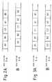
- Fig. 2 shows a condition wherein TDMA frames being sent from nearby radio base stations are not synchronous;
- Fig. 3 shows a condition wherein TDMA frames being sent from nearby radio base stations are synchronous;
- Fig. 4 is a diagram showing a positional relation of the control station and radio base stations to one another;
- Fig. 5 is a chart demonstrating how a set time delay of each time delay adjustment unit is determined;
- Fig. 6 is a block diagram schematically showing a specific construction of a control station;
- Fig. 7 is a block diagram schematically showing a specific construction of a synchronous signal generator unit;
- Fig. 8 is a block diagram schematically showing a specific construction of a radio base station;
- Fig. 9 is a block diagram showing a specific construction of a time delay adjustment unit; and
- Fig. 10 is a block diagram schematically showing a specific construction of a mobile station.
- Referring to Fig. 1 of the drawings, a TDMA mobile communications system has a
single control station 1 which governs a plurality of service areas. In the figure, the service areas are represented by two service areas 2-a and 2-b for illustration. Radio base stations 3-a and 3-b are situated in the service areas 2-a and 2-b, respectively, to cover the associated areas. Communication cables 4-a and 4-b connect respectively the radio base stations 3-a and 3-b to thecontrol station 1. Among a number of mobile stations, a givenmobile station 5 holds a digital mobile communication with thecontrol station 1 via the radio base station residing in the service area in which themobile station 5 is located, e.g., the radio base station 3-a of the service area 2-a by using an assigned carrier and an assigned time slot. The mobile stations may be a portable type or a vehicle-mounted type. - When the
mobile station 5 moves from the service area 2-a to the service area 2-b during communication, the communication is handed over to allow themobile station 5 to communicate with thecontrol station 1 via the radio base station 3-b situated in the service area 2-b, instead of the base station 3-a. - As shown in Fig. 2, assume that at the time of the hand-over the TDMA frames (represented by three frames A1, B1 and C1) being sent from the radio base station 3-a and the TDMA frames (represented by A2, B2 and C2) being sent from the radio base station 3-b are not synchronous. Then, the
mobile station 5 entered the service area 2-b has to set up frame synchronization with the radio base station 3-b before restarting the communication. The frame synchronization causes the frames A1, B1 and C1 from the radio base station 3-a and the frames A2, B2 and C2 from the radio base station 3-b to coincide with each other, as shown in Fig. 3. For the frame synchronization, TDMA frame generators each being installed in respective one of the radio base stations 3 (here, 3-a and 3-b) as will be described have to be reset to cause the transmission times of the frames from the individual TDMA frame generators into coincidence to less than the time in which a guard bit preceding each of the frames exists (eight bits; about 25 microseconds). During the frame synchronization, the communication is interrupted. Such interruption may reach 46 milliseconds, for example, under the GSM (Groupe Special Mobile) Recommendations due for launch in Europe in July 1991, because the Recommendations require a synchronization signal to be transmitted once in ten frames each of which has a time duration of 4.6 milliseconds. - In the embodiment shown in Fig. 1, a synchronous
signal generator unit 6 is located in the vicinity of thecontrol station 1, but it may be installed in thestation 1. Time delay adjustment units 7-a and 7-b are situated in the vicinity of and connected to the radio base stations 3-a and 3-b, respectively. The units 7-a and 7-b may also be installed in the base stations 3-a and 3-6, respectively. The synchronoussignal generator unit 6 and time delay adjustment units 7-a and 7-b cooperate to set up frame synchronization between the TDMA signals which the radio base stations 3-a and 3-b send. The synchronoussignal generator unit 6 has asynchronous pulse generator 11 and atime delay processor 12. The time delay adjustment units 7-a and 7-b each has a down-linksignal delay circuit 13 and an up-linksignal delay circuit 14. The synchronoussignal generator unit 6 is respectively connected to the radio base stations 3-a and 3-b by communication cables 15-a1 and 15-a2 and 15-b1 and 15-b2 and time delay adjustment units 7-a and 7-b. - The operation of the embodiment regarding the synchronous
signal generator unit 6 and time delay adjustment units 7-a and 7-b will be outlined. Thesynchronous pulse generator 11 sends one pulse (transmission pulse) per TDMA frame for frame synchronization. The time delay adjustment units 7-a and 7-b each returns the transmission pulse as first and second return pulses, respectively, as will be described. On detecting the first and second return pulses, thetime delay processor 12 determines first and second intervals between the transmission of the transmission pulse and the detection of the first and second pulses, respectively. With the first and second intervals, it is possible to determine first and second time delays between thecontrol station 1 and the radio base stations 3-a and 3-b, respectively. It is to be noted that most of the time delays is ascribable to the communication cables 15-a1, 15-a2, 15-b1 and 15-b2 or the communication cables 4a and 4b which are equivalent to the former. First and second set time delays to be set in the time delay adjustment units 7-a and 7-b, respectively, are calculated and then set in the units 7-a and 7-b. The time delay adjustment units 7-a and 7-b are manually or automatically controled to set time delays thereof on the basis of the first and second set time delays, respectively, by the down-linksignal delay circuit 13 and up-linksignal delay circuit 14. This will be described in detail later. As a result, the time delay adjustment units 7-a and 7-b delay a down-link signal and an up-link signal. - A reference will now be made to Figs. 3 and 5 for explaining how time delays between the
control station 1 and a plurality of radio base stations 3 (represented by base stations 3-a and 3-b) are measured and how additional time delays for resetting a plurality of TDMA frame generators at the same time are set. - To begin with, a procedure for measuring a time delay between the
control station 1 and a givenradio base station 3 will be described. As shown in Fig. 4, assume that the synchronoussignal generator unit 6 adjoining thecontrol station 1 is located at a point O, the radio base station 3-a and the associated time delay adjustment unit 7-a are located at a point A, and the radio base station 3-b and the associated time delay adjustment unit 7-b are located at a point B. Referring also to Fig. 5, the procedure for setting the time delay of the point A, i.e., the time delay adjustment unit 7-a begins with a step of setting the time delays of the down-link and up-linksignal delay circuits signal delay circuit 14 to the time delay processor 12 (point O) as a return pulse, as indicated by a dashed line in Fig. 5. The interval ta between the transmission of the transmission pulse and the detection of the return pulse is the reciprocation time delay between the points O and A (mainly ascribable to the communication cables 15-a1 and 15-a2). In the same manner, a reciprocation time delay tb between the points O and B is determined by detecting a return pulse from the time delay adjustment unit 7-b. - How additional time delays (set time delays) are set in the time
delay adjustment units 7 will be described. In order for the radio base stations 3-a and 3-b to set up frame synchronization, an arrangement should only be made such that the transmission pulse sent from thesynchronous pulse generator 11 reaches the base stations 3-a and 3-b at the same time. For this purpose, time delays are set by a specific procedure as will be described. The periods of time in which thetime delay processor 12 receives return pulses from the time delay adjustment units 7-a and 7-b as measured from the time when thesynchronous pulse generator 11 sent a transmission pulse both are set to be T (open to choice). An arrangement is made such that in a given timedelay adjustment unit 7 the down-link and up-linksignal delay circuits radio base stations 3 in a period of time of T/2. Specifically, thetime delay processor 12 determines a first set time delay (T-ta) and a second set time delay (T-tb) associated with the radio base stations 3-a and 3-b, respectively, on the basis of the measured time delays ta and tb. The so determined set time delays (T-ta) and (T-tb) are provided to thecontrol station 1 which in turn transmits these time delays (T-ta) and (T-tb) to the base stations 3-a and 3-b through the communications lines 4-a and 4-b, respectively. The time delays (T-ta) and (T-tb) may be displayed on a display, not shown, which may be provided on the synchronouspulse generator unit 6. The time delays (T-ta) and (T-tb) may also be respectively reported to the radio base stations 3-a and 3-b by telephone or similar implementation. In response to the time delays, the radio base stations 3-a and 3-b set the set time delays in the associated time delay adjustment units 7-a and 7-b. In the time delay adjustment unit 7-a, a time delay of (T-ta)/2 is set in each of the down-link and up-linksignal delay circuits signal delay circuits - In the above condition, a transmission pulse from the
synchronous pulse generator 11, i.e., a pulse sent from the point O is delayed by (T-ta) at the point A, delayed by (T-tb) at the point B, and then inputted as a return pulse to the point O, i.e., thetime delay processor 12 in the time T. - The
signal delay circuits 14 each is rendered inoperative as soon as the set time delay is set in the associated time delay adjustment unit 7-a or 7-b. - Once the set time delays are set in the individual time delay adjustment units 7-a and 7-b as stated above, a transmission pulse from the synchronous
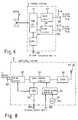
signal generator unit 6 arrives at the radio base stations 3-a and 3-b at the point P shown in Fig. 5, i.e., in the period of time of T/2 with no regard to the lengths of thecommunications cables 4 interconnecting thecontrol station 1 andradio base stations 3. Theradio base stations 3 each uses the arrived transmission pulse for resetting a timing pulse generator thereof. As a result, the mobile station is capable of establishing synchronization among the TDMA frames being transmitted from all of theradio base stations 3 instantaneously. - Referring to Fig. 6, a specific construction of the
control station 1 will be described. As shown, thecontrol station 1 is connected at one signal terminal to a public switching telephone network (PSTN) 21 and at the other signal terminals to the radio base stations 3-a and 3-b. A switchingcircuit 41 which is connected to a central processing unit (CPU) 44 governing theentire control station 1, performs the switching operation with respect to themobile station 5. The switchingcircuit 41 is connected at one signal terminal to thePSTN 21 and at the other signal terminals totrunk circuits trunk circuits control station 1 and radio base stations 3-a and 3-b beforehand. - When the reciprocation time delays ta and tb are measured, the
CPU 44 controls the base stations 3-a and 3-b to return a transmission pulse as a return pulse. At the time of setting the set time delays in the time delay adjustment units 7-a and 7-b, theCPU 44 sequentially sends to the base stations 3-a and 3-b the set time delays with control signals causing the base stations 3-a and 3-b to set the time delays in the units 7-a and 7-b, respectively. - The hand-over of communication that occurs after the time delays have been set in the time delay adjustment units 7-a and 7-b will be described with reference to Figs. 1 and 6. When the
mobile station 5 is located in the service area 2-a, it holds a communication while setting up frame synchronization with the radio base station 3-a. In this condition, the switchingcircuit 41 of thecontrol station 1 is connected to thetrunk circuit 42. As themobile station 5 approaches the service area 2-b, its communication is handed over from the service area 2-a to the service area 2-b and thestation 5 starts communicating with the radio base station 3-b. At this instant, the switchingcircuit 41 is caused into connection with thetrunk circuit 43. Since the time delay of the reset pulse (frame synchronizing pulse) between thecontrol station 1 and the base station 3-a and the time delay of the reset pulse between thecontrol station 1 and the base station 3-b are substantially equal, themobile station 5 sets up frame synchronization with the base station 3-b immediately. Hence, themobile station 5 can start communicating with the radio base station 3-b without the voice being interrupted. - It is noteworthy that the set time delays need only to be set once before the start of operation of the
radio base stations 3 and do not have to be adjusted despite any possible changes in the communication conditions. - Fig. 7 shows a specific construction of the
synchronous signal generator 6. As shown, thesynchronous signal generator 6 has asignal generator 71 for generating a clock, and acounter 72 which divides the frequency of the clock to produce pulses whose period corresponds to one TDMA frame. Abuffer circuit 73 converts the signal level of the output pulses of thecounter 72 and delivers sequentially the resulting pulses to a plurality of down-linksignal delay circuits 13 which are connected to the radio base stations. Abuffer circuit 74 sequentially receives pulses (return pulses) coming in over a plurality of up-linksignal delay circuits 14 which are also connected to theradio base stations 3. Acounter 75 is reset by the output pulses of thecounter 72 and counts time on the basis of the clock fed from thesignal generator 71. Alatch circuit 76 receives the time counted by thecounter 75 and latches it in response to a pulse signal from thebuffer circuit 74. The latched time is written to theCPU 44 of thecontrol station 1. Thesignal generator 71, counter 72 andbuffer circuit 73 constitute thesynchronous pulse generator 11 while thebuffer circuit 74, counter 75 andlatch circuit 76 constitute thetime delay processor 12. - A major function assigned to the synchronous
signal generator unit 6 is to generate synchronous signal pulses (transmission pulses) having a one TDMA frame period and sending them to the timedelay adjustment units 7. Another major function is to measure the delay times (pulse propagation times) between itself and the timedelay adjustment units 7 on the basis of the pulse returned from theunits 7 and to provide the results of measurement to theCPU 44 of thecontrol station 1. - Fig. 8 shows a specific construction of the
radio base station 3. As shown, theradio base station 3 has atrunk circuit 51 connected to thecontrol station 1, aburst control circuit 52, atransceiver 53 connected to theburst control circuit 52, anantenna 54 connected to thetransceiver 53 for transmitting and receiving a radio signal from themobile station 5, aCPU 55 circuit for supervising theentire base station 3, atiming pulse generator 56, and asignal generator 57 for outputting a clock. Theburst control circuit 52 transforms a voice signal from thetrunk circuit 51 and signaling from theCPU 55 into burst pulses in response to timing pulses which are generated by thetiming pulse generator 56, the burst pulses fed to thetransceiver 53. A signal sent from themobile station 5 and coming in through theantenna 54 is delivered to thetrunk circuit 51 andCPU circuit 55 via theburst control circuit 52. Thetiming pulse generator 56 generates TDMA timing pulses in response to the clock from thesignal generator 57. Thetiming pulse generator 56 is reset by a reset pulse (transmission pulse) sent from thesynchronous signal generator 6 via the down-link delay circuit 13 and a terminal 303, whereby a plurality ofradio base stations 3 are synchronized with respect to TDMA frames. Thetiming pulse generator 56 and burstcontrol circuit 52 in combination play the role of the previously stated TDMA frame generator. - The
CPU 55 is also connected to thedelay adjustment unit 7 via a terminal 302 to control theunit 7. More specifically, theCPU 55 causes theunit 7 to return a transmission pulse to the synchronoussignal generator unit 6 at the time of measuring the reciprocation time delay ta or tb. When the set time delay is set, theCPU 55 sets the set time delay in theunit 7 in response to the control signal from thecontrol station 1. - Referring to Fig, 9, a specific construction of the time
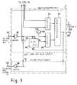
delay adjustment unit 7 having the down-linksignal delay circuit 13 and up-linksignal delay circuit 14 is shown. The down-linksignal delay circuit 13 has alatch circuit 81 in which theCPU 55 of the associatedradio base station 3, for example, writes a set time delay. Abuffer circuit 82 receives a transmission pulse from thesynchronous pulse generator 11. Aswitch 83 is connected to thebuffer circuit 82 at one end thereof and under the control ofCPU 55. A flip-flop 84 has a set input terminal to which a pulse from thebuffer circuit 82 is applied. Asignal generator 85 generates a clock. Acounter 86 is reset by an output of the flip-flop 84 and counts time on the basis of the clock. Acomparator 87 compares the increasing output of thecounter 86 with the constant output of thelatch circuit 81 and, when they coincide, produces a pulse. The output pulse of thecomparator 87 is applied as a reset pulse to the reset input terminal of the flip-flop 84 and thetiming pulse generator 56 of the associatedradio base station 3. At the same time, the output pulse or thecomparator 87 is fed to the up-linksignal delay circuit 14 as a return pulse. - The up-link
signal delay circuit 14 has abuffer circuit 88 which is connected to the other end of theswitch 83 for returning a transmission pulse fed from thebuffer circuit 82 to thesynchronous pulse generator 11. Thiscircuit 14, like thecircuit 13, has a latch circuit, flip-flop, signal generator counter, and comparator, although not shown in the figure. On receiving the reset pulse or return pulse from thecomparator 87 of thecircuit 13, thecircuit 14 delays it by a set time delay and sends the delayed pulse as a return pulse via thebuffer circuit 88. - A major function of the time
delay adjustment unit 7 is to return, at the time of measurement of a reciprocation time delay between thecontrol station 1 and theradio base station 3, a transmission pulse from thesynchronous signal generator 6 by way of thebuffer circuits switch 83. Another major function is to delay a transmission pulse from thebuffer circuit 82 by a set time delay and sending the delayed transmission pulse to thetiming pulse generator 56 of thebase station 3 via thecomparator 87. Still another major function is to delay a transmission pulse from thecomparator 87 by a set time delay and sending the delayed pulse as a return pulse to thetime delay processor 12 which is connected to the output of the up-linksignal delay circuit 14. - When a transmission pulse is applied to the flip-
flop 84 of the timedelay adjustment unit 7 via thebuffer circuit 82, thecounter 86 is set and starts counting the clock from thesignal generator 85 while inputting the count to thecomparator 87. The time delay measured at the time of time delay setting stage is stored in thelatch circuit 81 beforehand by, for example, theCPU 55 of theradio base station 7. Thecomparator 87 compares the value of thelatch circuit 81 and that of thecounter 86 and, when they coincide, outputs a pulse. This pulse resets the TDMAtiming pulse generator 56 of thebase station 3 and thecounter 86 via the flip-flop 84. - As shown in Fig. 10, the
mobile station 5 has anantenna 61 for transmitting and receiving TDMA signals from the radio base stations 3-a and 3-b over electro-magnetic waves. Theantenna 61 is connected to atransceiver 62 which is in turn connected to aburst control circuit 63. Ahandset 64 is connected to theburst control circuit 63 and interfaces the user to themobile station 5. Atiming pulse generator 65 is also connected to theburst control circuit 63. ACPU 66 is connected to theburst control circuit 63 andtiming pulse generator 65 for supervising the entiremobile station 5. Asignal generator 67 generates a clock. Theburst control circuit 63 transforms a voice signal from thehandset 64 and the signaling from theCPU 66 into bursts (frames) in response to timing pulses which are fed thereto from thetiming pulse generator 65. These bursts are delivered to thetransceiver 62. A signal sent from themobile station 5 and come in through theantenna 61 is fed to thehandset 64 andCPU 66. Thetiming pulse generator 65 generates TDMA timing pulses in response to the clock from thesignal generator 67. TheCPU 66 controls thetiming pulse generator 65 in response to the TDMA frame synchronizing signals being sent from theradio base stations 3, thereby setting up frame synchronization between signals received from thebase stations 3. - In summary, in accordance with the present invention, each radio base station has a time delay adjustment unit while a synchronous pulse generator is located in close proximity to a control circuit. The time delay adjustment units of the individual radio base stations delay a transmission pulse, or frame synchronizing pulse, sent from the synchronous pulse generator such that the pulse arrives at all of the base stations at the same time. This allows TDMA frame generators installed in the individual radio base stations to be reset at the same time, insuring TDMA frame synchronization among the base stations. Hence, a mobile station does not have to set up frame synchronization every time it is handed over from one service area to another. As a result, rapid hand-over of a mobile station is promoted, and the momentary cut-off of a signal is eliminated.
Claims (6)
- A TDMA digital mobile communications system comprising a control station (1), a plurality of radio base stations (3-a) each being located in respective one of service areas (2-a) which are governed by said control station and each comprising a TDMA frame generator (56), and a plurality of mobile stations (5) each being movable in said service areas while interchanging digital signals with said radio base stations located in said service areas by using an assigned time slot, characterized by
synchronous signal generating means (6) for transmitting a reset pulse for resetting the TDMA frame generators;
delaying means (7) for delaying said transmitted reset pulse, and inputting said delayed reset pulse to associated one of said radio base stations; and
means for applying said reset pulse inputted from said delaying means to associated one of said TDMA frame generators, wherein a time delay assigned to each of said delaying means (1) varies with a distance between said radio base station (3-a) and said control station (1) and is selected such that said reset pulse delayed by all of said radio base stations is inputted to all of said radio base stations at the same time wherein said delaying means (7) comprises returning means (14) for receiving said reset pulse and returning said reset pulse as a return pulse to said synchronous signal generating means (6), and wherein said synchronous signal generating means (6) comprises time delay determining means (12) for detecting a first time when said return pulse is received and, on the basis of a period of time defined by a second time when said reset pulse is transmitted and said first time when said reset pulse is received, determining a time delay of said reset pulse. - A system as claimed in claim 1, wherein said reset pulse is transmitted every TDMA frame.
- A system as claimed in claim 1 or 2, wherein said synchronous signal generating means (6) comprises:
signal generator means (71) for generating a clock;
first counter means (72) for dividing a frequency of said clock to generate said reset pulse having a period of one TDMA frame and transmitting said reset pulse to said delaying means;
second counter means (75) reset by said reset pulse fed from said first counter means for measuring a period of time until said return pulse of said reset pulse transmitted from said delaying means arrives by using said clock; and
latch circuit means (76) for latching said period of time measured by said second counter means. - A system as claimed in claim 1, 2, or 3 wherein said delaying means comprises:
latch circuit means (81) to which a set time delay is written via a set input terminal thereof;
flip-flop means (84) having a set input terminal for receiving said reset pulse;
signal generator means (85) for generating a clock;
counter means (86) reset by an output of said flip-flop means for counting time by using said clock signal; and
comparator means (87) for comparing the output of said latch circuit means and the output of said counter means and, when said outputs coincide, outputting a reset pulse while feeding said reset pulse to said flip-flop means as a reset pulse and to said radio base station as an output. - A system as claimed in claim 1 or 2, wherein
said synchronous signal generating means (6) is situated near or in said control station said delaying means is situated near or in said radio base stations,
said synchronous signal generating means comprises:
signal generator means (71) for generating a clock;
first counter means (72) for dividing a frequency of said clock signal to generate said reset pulse having a period of one TDMA frame;
second counter means (75) reset by said reset pulse outputted by said first counter means (72) for measuring a period of time from said resetting to arrival of a return pulse of said reset pulse by using said clock; and
latch circuit means (76) for latching said period of time measured by said second counter means;
said delaying means comprises:
latch circuit means (81) to which a set time delay is written via a set input terminal thereof;
flip-flop means (84) having a set input terminal for receiving a pulse signal;
signal generator means (85) for generating a clock;
third counter means (86) reset by an output of said flip-flop means for counting time by using said clock; and
comparator means (87) for comparing the output of said latch circuit means and the output of said third counter means and, when said outputs coincide, outputting a delayed pulse signal by delaying said pulse signal by said set time delay and feeding said delayed pulse signal to said flip-flop means (84) as a reset pulse and to said radio base station as an output pulse. - A system as claimed in claim 5, wherein said reset pulse generated by said synchronous signal generating means (6) is applied to said set input terminal of said flip-flop means (84) over a communications cable (15-a1, 15-a2), said output pulse produced by delaying said reset pulse being applied to said synchronous signal generating means over said communications cable.
Applications Claiming Priority (2)
| Application Number | Priority Date | Filing Date | Title |
|---|---|---|---|
| JP33638089 | 1989-12-27 | ||
| JP336380/89 | 1989-12-27 |
Publications (2)
| Publication Number | Publication Date |
|---|---|
| EP0437835A1 EP0437835A1 (en) | 1991-07-24 |
| EP0437835B1true EP0437835B1 (en) | 1995-04-26 |
Family
ID=18298541
Family Applications (1)
| Application Number | Title | Priority Date | Filing Date |
|---|---|---|---|
| EP90125511AExpired - LifetimeEP0437835B1 (en) | 1989-12-27 | 1990-12-27 | Frame synchronization system among multiple radio base stations for TDMA digital mobile communication system |
Country Status (6)
| Country | Link |
|---|---|
| US (1) | US5293380A (en) |
| EP (1) | EP0437835B1 (en) |
| AU (1) | AU647062B2 (en) |
| CA (1) | CA2033309C (en) |
| DE (1) | DE69018959T2 (en) |
| HK (1) | HK85497A (en) |
Families Citing this family (62)
| Publication number | Priority date | Publication date | Assignee | Title |
|---|---|---|---|---|
| US5228029A (en)* | 1990-02-27 | 1993-07-13 | Motorola, Inc. | Cellular tdm communication system employing offset frame synchronization |
| JP2880841B2 (en)* | 1991-11-30 | 1999-04-12 | 日本電気株式会社 | Digital radio telephone equipment |
| JPH0629910A (en)* | 1992-07-09 | 1994-02-04 | Nec Corp | Inter radio base station synchronization system |
| FR2695777B1 (en)* | 1992-09-15 | 1994-10-14 | Alcatel Radiotelephone | Method for transmitting time advance information to a mobile moving in cells of a GSM network with asynchronous BTS. |
| GB9303994D0 (en)* | 1993-02-26 | 1993-04-14 | Shaye Communications Ltd | Improvements relating to duplex communications systems |
| EP0613276B1 (en)* | 1993-02-26 | 1996-02-07 | Peacock Uk Limited | System for synchronisation of a plurality of transmitters |
| DE69422852T2 (en)* | 1993-05-26 | 2000-06-15 | Nec Corp., Tokio/Tokyo | Network synchronization for cellular TDMA communication using signals from mobile stations in neighboring cells |
| WO1994028643A1 (en)* | 1993-05-27 | 1994-12-08 | Nokia Telecommunications Oy | Base station for a tdma cellular radio network |
| DE4317895C2 (en)* | 1993-05-28 | 1996-11-14 | Siemens Ag | Method for synchronizing base stations in a multi-cellular, wireless telephone system |
| BR9405406A (en)* | 1993-06-14 | 1999-09-08 | Ericsson Telefon Ab L M | Code division susceptible multiple access process and system for cellular communication systems |
| ES2078150B1 (en)* | 1993-06-25 | 1998-01-01 | Alcatel Standard Electrica | SUBSYSTEM OF COMMUNICATIONS BETWEEN BASE STATIONS AND BASE STATION CONTROLLERS IN COMMUNICATION SYSTEMS TO GUSTS. |
| US5430724A (en)* | 1993-07-02 | 1995-07-04 | Telefonaktiebolaget L M Ericsson | TDMA on a cellular communications system PCM link |
| NZ264830A (en)* | 1993-11-15 | 1996-11-26 | Alcatel Australia | Extending the range of a time division multiple access cellular communication system |
| FI94917C (en)* | 1994-02-14 | 1995-11-10 | Nokia Telecommunications Oy | Method for controlling the timing of transmission in a mobile station in a digital TDMA mobile communication system as well as a digital TDMA mobile communication system |
| US5541979A (en)* | 1994-03-08 | 1996-07-30 | Allen Telecom Group, Inc. | Cell extender with timing alignment for use in time division multiple-access and similar cellular telephone systems |
| DE4407794A1 (en)* | 1994-03-09 | 1995-09-14 | Sel Alcatel Ag | Synchronization of the pulse frame |
| US5787078A (en)* | 1994-03-09 | 1998-07-28 | Alcatel N.V. | Frame Synchronization method |
| DE69533788T2 (en)* | 1994-05-20 | 2005-12-22 | Ntt Docomo Inc. | GENTLE RADIATION SCHEME FOR CELLULAR MOBILE RADIO COMMUNICATION SYSTEM |
| WO1995034138A1 (en)* | 1994-06-07 | 1995-12-14 | Celsat America, Inc. | Communications system |
| JP2606590B2 (en)* | 1994-06-30 | 1997-05-07 | 日本電気株式会社 | Inter-station synchronization method |
| US5550828A (en)* | 1994-06-30 | 1996-08-27 | Motorola, Inc. | Method of handing off a communication unit in a cellular communication system |
| US5586119A (en)* | 1994-08-31 | 1996-12-17 | Motorola, Inc. | Method and apparatus for packet alignment in a communication system |
| GB2296626B (en)* | 1994-12-23 | 1999-07-28 | Nokia Mobile Phones Ltd | Multi-mode radio telephone |
| FI100159B (en)* | 1995-01-19 | 1997-09-30 | Nokia Telecommunications Oy | Synchronization of a telecommunication connection in a mobile communication system |
| GB2301734B (en)* | 1995-05-31 | 1999-10-20 | Motorola Ltd | Communications system and method of operation |
| US5805576A (en)* | 1995-10-18 | 1998-09-08 | Cellular Telecom, Ltd. | Method and apparatus for TDMA wireless communication employing collector arrays for range extension |
| US5884177A (en)* | 1995-10-25 | 1999-03-16 | Northern Telecom Limited | Cellular communication system and method providing improved handoff capability |
| WO1997023047A2 (en)* | 1995-12-15 | 1997-06-26 | Telefonaktiebolaget Lm Ericsson | Discrete phase locked loop |
| JP2785789B2 (en)* | 1996-02-09 | 1998-08-13 | 日本電気株式会社 | Digital mobile communication system |
| SE518132C2 (en)* | 1996-06-07 | 2002-08-27 | Ericsson Telefon Ab L M | Method and apparatus for synchronizing combined receivers and transmitters in a cellular system |
| DE19625219C1 (en)* | 1996-06-24 | 1997-10-30 | Siemens Ag | Propagation time difference compensation device esp. for digital transmissions |
| KR100407335B1 (en)* | 1996-10-08 | 2004-01-24 | 삼성전자주식회사 | Subscriber interface apparatus of key telephone system and method therefor |
| US6359866B1 (en) | 1996-12-17 | 2002-03-19 | Telefonaktiebolaget Lm Ericsson (Publ) | Base station having transceivers used for communicating voice and packet data signals |
| DE69738253T2 (en)* | 1996-12-26 | 2008-08-07 | Ntt Mobile Communications Network Inc. | TRANSMITTER RECEIVER IN FRAMEWORK MODE |
| US5978680A (en)* | 1996-12-30 | 1999-11-02 | Nokia Telecommunications Oy | Transmission method and a cellular radio system |
| US6038458A (en)* | 1996-12-30 | 2000-03-14 | Nokia Telecommunications Oy | Method for selecting a signal, and a cellular radio system |
| US5825760A (en)* | 1996-12-30 | 1998-10-20 | Nokia Telecommunications Oy | Transmission method and a cellular radio system |
| EP0851608A1 (en)* | 1996-12-31 | 1998-07-01 | TELEFONAKTIEBOLAGET L M ERICSSON (publ) | Transmission time delay measurement at transmission paths in a radio telecommunication system |
| GB2321827B (en)* | 1997-01-31 | 2001-06-13 | Ericsson Telefon Ab L M | Telecommunications system |
| DE19714494C1 (en)* | 1997-04-08 | 1998-10-01 | Siemens Ag | Method and device for synchronizing a clock generator |
| DE19716344C2 (en)* | 1997-04-18 | 2000-02-10 | Siemens Ag | Synchronization method and synchronization device |
| DE19723497A1 (en)* | 1997-06-05 | 1998-12-10 | Rohde & Schwarz | Radio network especially for paging systems |
| SE509836C2 (en)* | 1997-06-13 | 1999-03-15 | Ericsson Telefon Ab L M | Procedure and arrangement in a radio communication system |
| JPH11146444A (en)* | 1997-11-11 | 1999-05-28 | Nec Corp | Synchronization establishing system for mobile communication base station network |
| US6735222B1 (en)* | 1998-08-14 | 2004-05-11 | Telefonaktiebolaget Lm Ericsson (Publ) | System and method for time slot offset evaluation in an asynchronous TDMA network |
| FI112567B (en)* | 1998-10-23 | 2003-12-15 | Nokia Corp | Synchronization of terminals in radio link system |
| US6760316B1 (en)* | 1998-10-30 | 2004-07-06 | Broadcom Corporation | Method and apparatus for the synchronization of multiple cable modem termination system devices |
| DE50011113D1 (en)* | 1999-01-13 | 2005-10-13 | Siemens Ag | METHOD FOR SWITCHING ON A COMMUNICATION CONNECTION TO ANOTHER CHANNEL (HANDOVER) |
| CA2365007A1 (en)* | 1999-02-26 | 2000-08-31 | Edward G. Tiedemann, Jr. | Method and system for handoff between an asynchronous cdma base station and a synchronous cdma base station |
| US7319686B1 (en)* | 1999-03-18 | 2008-01-15 | Industrial Technology Research Institute | Frame synchronization in multi-cell systems with a data interface |
| DE19917337C2 (en)* | 1999-04-16 | 2002-02-28 | Infineon Technologies Ag | Method and device for synchronizing a mobile radio receiver with a frame structure of a radio signal |
| DE19926830C2 (en)* | 1999-06-12 | 2003-03-27 | Tenovis Gmbh & Co Kg | Process, headquarters and module |
| GB2386801B (en) | 1999-08-24 | 2004-03-24 | Roke Manor Research | A method of locating a mobile station within a telecommunications cell forming part of a telecommunications system |
| AU2756201A (en)* | 2000-01-07 | 2001-07-16 | Mdiversity, Inc. | Dynamic channel allocation in multiple-access communication systems |
| US6804527B2 (en) | 2001-01-19 | 2004-10-12 | Raze Technologies, Inc. | System for coordination of TDD transmission bursts within and between cells in a wireless access system and method of operation |
| CN102685836B (en) | 2001-08-14 | 2015-07-08 | 高通股份有限公司 | Methods and apparatus for wireless network connectivity |
| KR100891785B1 (en)* | 2002-04-27 | 2009-04-07 | 삼성전자주식회사 | Soft Handover Method for Multicast Multimedia Broadcasting Service in Code Division Multiple Access Mobile Communication System |
| KR100503039B1 (en)* | 2002-11-25 | 2005-07-22 | 삼성테크윈 주식회사 | Method to control operation of digital camera for user to easily take an identification photograph |
| WO2005057970A1 (en)* | 2003-12-10 | 2005-06-23 | Matsushita Electric Industrial Co., Ltd. | Inter-station transmission method, radio base station monitoring method, and device using the method |
| DE102005024759A1 (en)* | 2005-05-31 | 2006-12-07 | Bosch Rexroth Ag | Method for time correction in a communication structure |
| KR100965672B1 (en)* | 2005-07-06 | 2010-06-24 | 삼성전자주식회사 | System and method for state synchronization between base station and mobile station in mobile communication system |
| KR102602390B1 (en)* | 2019-01-03 | 2023-11-16 | 삼성전자주식회사 | Apparatus and method for estimating delay time in synchronization system |
Family Cites Families (13)
| Publication number | Priority date | Publication date | Assignee | Title |
|---|---|---|---|---|
| US3879580A (en)* | 1972-11-24 | 1975-04-22 | Hughes Aircraft Co | Data terminal for use with TDMA processing repeater |
| JPS5949744B2 (en)* | 1976-11-11 | 1984-12-04 | 日本電気株式会社 | Frame synchronization circuit |
| FR2502426A1 (en)* | 1981-03-20 | 1982-09-24 | Trt Telecom Radio Electr | SYSTEM FOR TRANSMITTING INFORMATION BETWEEN A MAIN STATION AND SECONDARY STATIONS OPERATING IN ACCORDANCE WITH A TDMA METHOD |
| JPS58154947A (en)* | 1982-03-10 | 1983-09-14 | Nec Corp | Time axis adjusting system of radio line by time division multiple address |
| US4581003A (en)* | 1983-07-08 | 1986-04-08 | Toppan Printing Co., Ltd. | Method for manufacturing an angled and cylindrical container |
| DE3527329A1 (en)* | 1985-07-31 | 1987-02-05 | Philips Patentverwaltung | DIGITAL RADIO TRANSMISSION SYSTEM WITH VARIABLE TIME SLOT DURATION OF TIME SLOTS IN TIME MULTIPLEX FRAME |
| DE3607687A1 (en)* | 1986-03-08 | 1987-09-10 | Philips Patentverwaltung | METHOD AND CIRCUIT ARRANGEMENT FOR SWITCHING A RADIO CONNECTION INTO ANOTHER RADIO CELL OF A DIGITAL RADIO TRANSMISSION SYSTEM |
| JPS62214739A (en)* | 1986-03-15 | 1987-09-21 | Nec Corp | Synchronization control system |
| US4714899A (en)* | 1986-09-30 | 1987-12-22 | Motorola, Inc. | Frequency synthesizer |
| JPH0616603B2 (en)* | 1988-01-14 | 1994-03-02 | 東京電力株式会社 | Mobile communication system |
| JPH0622345B2 (en)* | 1988-01-14 | 1994-03-23 | 東京電力株式会社 | Mobile communication system |
| SE460749B (en)* | 1988-03-15 | 1989-11-13 | Ericsson Telefon Ab L M | PROCEDURE TO TRANSFER DATA INFORMATION IN A CELL-DIVIDED MOBILE RADIO COMMUNICATION SYSTEM |
| US4972410A (en)* | 1989-07-20 | 1990-11-20 | Electrocom Automation, Inc. | Method and apparatus for controlling signal coherency in simulcast systems |
- 1990
- 1990-12-27CACA002033309Apatent/CA2033309C/ennot_activeExpired - Fee Related
- 1990-12-27EPEP90125511Apatent/EP0437835B1/ennot_activeExpired - Lifetime
- 1990-12-27DEDE69018959Tpatent/DE69018959T2/ennot_activeExpired - Fee Related
- 1990-12-27AUAU68538/90Apatent/AU647062B2/ennot_activeCeased
- 1990-12-27USUS07/634,894patent/US5293380A/ennot_activeExpired - Fee Related
- 1997
- 1997-06-19HKHK85497Apatent/HK85497A/ennot_activeIP Right Cessation
Also Published As
| Publication number | Publication date |
|---|---|
| AU6853890A (en) | 1991-07-11 |
| EP0437835A1 (en) | 1991-07-24 |
| CA2033309A1 (en) | 1991-06-28 |
| CA2033309C (en) | 1998-02-10 |
| DE69018959D1 (en) | 1995-06-01 |
| HK85497A (en) | 1997-06-27 |
| DE69018959T2 (en) | 1995-09-21 |
| US5293380A (en) | 1994-03-08 |
| AU647062B2 (en) | 1994-03-17 |
Similar Documents
| Publication | Publication Date | Title |
|---|---|---|
| EP0437835B1 (en) | Frame synchronization system among multiple radio base stations for TDMA digital mobile communication system | |
| US5912886A (en) | Digital mobile communication system capable of establishing mutual synchronization among a plurality of radio base stations | |
| US5809426A (en) | Arrangement in mobile telecommunications systems for providing synchronization of transmitters of base stations | |
| EP1201050B1 (en) | Method and apparatus for sequentially synchronizing a radio network | |
| KR100297894B1 (en) | Synchronization in tdma systems in a non-real-time fashion | |
| US5519710A (en) | Network synchronization for TDMA cellular communication using signals from mobile stations in neighboring cells | |
| US6920155B2 (en) | Embedded loop delay compensation circuit for multi-channel transceiver | |
| KR100512543B1 (en) | Synchronizing base stations in a wireless telecommunications system | |
| EP0950290B1 (en) | Transmission time delay measurement at transmission paths in a radio telecommunication system | |
| US5920557A (en) | Radio base station inter-station synchronizing circuit | |
| US6707807B1 (en) | Reception time of messages in access channels of TDMA mobile communication system controlled by transmitting device | |
| JP2638295B2 (en) | TDMA digital mobile communication system | |
| US5408517A (en) | Method and apparatus for handoff synchronization | |
| WO1992013417A1 (en) | Simulcast transmission system having predetermined launch times | |
| CN1140002A (en) | Burst Alignment Procedure | |
| JP2001501795A (en) | Dual-mode portable telephone unit | |
| JPH07193859A (en) | Inter-base station tdma frame synchronization system in mobile communication | |
| JPH08105966A (en) | Surveillance radar device | |
| JP2731640B2 (en) | TDMA frame synchronization method between multiple radio base stations | |
| JPH06303182A (en) | Inter-office phase synchronizing system and device used for this | |
| JPS6327133A (en) | System for synchronizing phase of transmission signal from plural stations | |
| JPH02276322A (en) | Automatic inter-station phase compensating system | |
| RU2134487C1 (en) | Method for simultaneous paging in paging system | |
| GB2316835A (en) | Synchronisation of electronic apparatus | |
| JPH0730963A (en) | Inter-station phase synchronization system |
Legal Events
| Date | Code | Title | Description |
|---|---|---|---|
| PUAI | Public reference made under article 153(3) epc to a published international application that has entered the european phase | Free format text:ORIGINAL CODE: 0009012 | |
| 17P | Request for examination filed | Effective date:19901227 | |
| AK | Designated contracting states | Kind code of ref document:A1 Designated state(s):DE FR GB NL SE | |
| 17Q | First examination report despatched | Effective date:19930519 | |
| GRAA | (expected) grant | Free format text:ORIGINAL CODE: 0009210 | |
| AK | Designated contracting states | Kind code of ref document:B1 Designated state(s):DE FR GB NL SE | |
| REF | Corresponds to: | Ref document number:69018959 Country of ref document:DE Date of ref document:19950601 | |
| ET | Fr: translation filed | ||
| PLBE | No opposition filed within time limit | Free format text:ORIGINAL CODE: 0009261 | |
| STAA | Information on the status of an ep patent application or granted ep patent | Free format text:STATUS: NO OPPOSITION FILED WITHIN TIME LIMIT | |
| 26N | No opposition filed | ||
| PGFP | Annual fee paid to national office [announced via postgrant information from national office to epo] | Ref country code:SE Payment date:19971204 Year of fee payment:8 | |
| PGFP | Annual fee paid to national office [announced via postgrant information from national office to epo] | Ref country code:NL Payment date:19971231 Year of fee payment:8 | |
| PG25 | Lapsed in a contracting state [announced via postgrant information from national office to epo] | Ref country code:SE Free format text:LAPSE BECAUSE OF NON-PAYMENT OF DUE FEES Effective date:19981228 | |
| PG25 | Lapsed in a contracting state [announced via postgrant information from national office to epo] | Ref country code:NL Free format text:LAPSE BECAUSE OF NON-PAYMENT OF DUE FEES Effective date:19990701 | |
| NLV4 | Nl: lapsed or anulled due to non-payment of the annual fee | Effective date:19990701 | |
| PGFP | Annual fee paid to national office [announced via postgrant information from national office to epo] | Ref country code:FR Payment date:20011212 Year of fee payment:12 | |
| PGFP | Annual fee paid to national office [announced via postgrant information from national office to epo] | Ref country code:GB Payment date:20011227 Year of fee payment:12 | |
| REG | Reference to a national code | Ref country code:GB Ref legal event code:IF02 | |
| PGFP | Annual fee paid to national office [announced via postgrant information from national office to epo] | Ref country code:DE Payment date:20020109 Year of fee payment:12 | |
| PG25 | Lapsed in a contracting state [announced via postgrant information from national office to epo] | Ref country code:GB Free format text:LAPSE BECAUSE OF NON-PAYMENT OF DUE FEES Effective date:20021227 | |
| PG25 | Lapsed in a contracting state [announced via postgrant information from national office to epo] | Ref country code:DE Free format text:LAPSE BECAUSE OF NON-PAYMENT OF DUE FEES Effective date:20030701 | |
| GBPC | Gb: european patent ceased through non-payment of renewal fee | Effective date:20021227 | |
| PG25 | Lapsed in a contracting state [announced via postgrant information from national office to epo] | Ref country code:FR Free format text:LAPSE BECAUSE OF NON-PAYMENT OF DUE FEES Effective date:20030901 | |
| REG | Reference to a national code | Ref country code:FR Ref legal event code:ST |