EP0429736B1 - Spraying nozzle for a mixture of fluids - Google Patents
Spraying nozzle for a mixture of fluidsDownload PDFInfo
- Publication number
- EP0429736B1 EP0429736B1EP19890460042EP89460042AEP0429736B1EP 0429736 B1EP0429736 B1EP 0429736B1EP 19890460042EP19890460042EP 19890460042EP 89460042 AEP89460042 AEP 89460042AEP 0429736 B1EP0429736 B1EP 0429736B1
- Authority
- EP
- European Patent Office
- Prior art keywords
- chamber
- lance
- wall
- fluid
- holes
- Prior art date
- Legal status (The legal status is an assumption and is not a legal conclusion. Google has not performed a legal analysis and makes no representation as to the accuracy of the status listed.)
- Expired - Lifetime
Links
- 239000012530fluidSubstances0.000titleclaimsdescription23
- 239000000203mixtureSubstances0.000titleclaimsdescription18
- 238000005507sprayingMethods0.000titledescription4
- 239000007788liquidSubstances0.000claimsdescription10
- 230000002093peripheral effectEffects0.000claimsdescription2
- XLYOFNOQVPJJNP-UHFFFAOYSA-NwaterSubstancesOXLYOFNOQVPJJNP-UHFFFAOYSA-N0.000description15
- 230000000694effectsEffects0.000description2
- IMACFCSSMIZSPP-UHFFFAOYSA-Nphenacyl chlorideChemical compoundClCC(=O)C1=CC=CC=C1IMACFCSSMIZSPP-UHFFFAOYSA-N0.000description2
- 239000003491tear gasSubstances0.000description2
- 238000004140cleaningMethods0.000description1
- 230000006835compressionEffects0.000description1
- 238000007906compressionMethods0.000description1
- 238000005202decontaminationMethods0.000description1
- 230000003588decontaminative effectEffects0.000description1
- 230000003247decreasing effectEffects0.000description1
- 238000002474experimental methodMethods0.000description1
- 238000005187foamingMethods0.000description1
- 239000007789gasSubstances0.000description1
- 239000008240homogeneous mixtureSubstances0.000description1
- 238000004519manufacturing processMethods0.000description1
- 230000000750progressive effectEffects0.000description1
- 238000007789sealingMethods0.000description1
- 229910001220stainless steelInorganic materials0.000description1
- 239000010935stainless steelSubstances0.000description1
- 239000000126substanceSubstances0.000description1
- 238000011144upstream manufacturingMethods0.000description1
Images

Classifications
- A—HUMAN NECESSITIES
- A62—LIFE-SAVING; FIRE-FIGHTING
- A62C—FIRE-FIGHTING
- A62C31/00—Delivery of fire-extinguishing material
- A62C31/02—Nozzles specially adapted for fire-extinguishing
- A62C31/12—Nozzles specially adapted for fire-extinguishing for delivering foam or atomised foam
- B—PERFORMING OPERATIONS; TRANSPORTING
- B05—SPRAYING OR ATOMISING IN GENERAL; APPLYING FLUENT MATERIALS TO SURFACES, IN GENERAL
- B05B—SPRAYING APPARATUS; ATOMISING APPARATUS; NOZZLES
- B05B7/00—Spraying apparatus for discharge of liquids or other fluent materials from two or more sources, e.g. of liquid and air, of powder and gas
- B05B7/02—Spray pistols; Apparatus for discharge
- B05B7/04—Spray pistols; Apparatus for discharge with arrangements for mixing liquids or other fluent materials before discharge
Definitions
- the present inventionrelates to a lance for spraying a mixture of fluids and, more particularly a mixture of water with one or more other liquids or gases.
- Water lancesare also used in law enforcement operations and, in this case, attempts are made to add tear-gas or incapacitating products to the water.
- Fluid mixing lancescan also be used in the chemical industry and for cleaning, decontamination, etc.
- the liquid mixing lance according to the invention as described in rev. 1,is intended to meet two conditions: on the one hand, to project an effective jet over a long distance and, on the other hand, to instantly produce a homogeneous mixture of liquids.
- a lance for spraying a mixture of fluidscomprising a main liquid inlet tube followed by a first chamber with divergent conical internal and external walls, the external wall extending the tube. inlet and the inner wall having its apex opposite the axis of the tubing, said outer wall being pierced with holes through which at least one additional fluid is sprayed into said first chamber, which communicates through other practically longitudinal holes drilled in the periphery of the base of said internal wall with a second chamber bounded by a converging conical side wall which opens into a relatively long outlet pipe.
- the peripheral gap between the conical internal and external walls of the first chamberis closed by a cylindrical ferrule.
- the conical side wall of the second chambercomprises two trunks of cone of angles at the decreasing top from the entry towards the exit.
- the outlet pipe of the lanceis surrounded by an air passage sleeve whose diameter, beyond the outlet of said outlet pipe, rapidly reduces to a value slightly greater than that of the diameter of the outlet pipe.
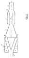
- the lance of FIG. 1comprises an inlet part 1, an intermediate part 2 and an outlet part 3.
- the inlet part 1comprises a part with a cylindrical internal surface 4 followed by a part with a conical internal surface 5, the cone of the part 5 being divergent, considering the direction of flow indicated by the arrows F.
- the cylindrical part 4is designed to be connected to a pressurized water pipe, not shown.
- the conical part 5is pierced with a number of holes 6 which are intended to be connected to a source of fluid to be mixed with water, which will be described in more detail below.
- the intermediate piece 2is conical internally and externally, the tips of the cones being turned towards that of the cone of the part 5.
- the upstream surface 7 of the part 2has an apex angle substantially equal to that of the part 5 as its downstream surface 8.
- the base 9 of the conical part 2has the shape of a circular crown pierced with longitudinal holes 10. In the example described, the edge of the crown 9 is connected to the base of the part 5 of the part 1 by a cylindrical part 11 which serves to limit transversely a first conical chamber divergent A in which the water entering through part 4 mixes with the fluid leaving holes 6.
- the outlet part 3comprises a cylindrical part 12 which surrounds the crown 9, a converging conical part 13 and a cylindrical part 14.
- the chamber B, between the diverging conical surface 8 and the converging conical part 13creates a turbulence which ensures mixing homogeneous water and additional fluid which leaves, at high speed, through part 14.
- the sum of the cross sections of the holes 10is substantially equal to the sum of the cross section of the hole 4 and that of the holes 6. Thus, no pressure drop is created during the operation of mixing the fluids.
- the cross section of the part 14is less than this sum in order to impart a high speed to the fluid leaving the lance.
- a cylindrical ferrule 15is provided which is externally threaded at its two ends, for screwing, on the one hand, the internal tapped surface of the part 12 of the part 3 and, d on the other hand, the internal threaded surface of the bowl 16 of an annular part 17 serving for the supply of fluid intended to pass through the holes 6.
- the central part of the bottom of the bowl 16is pierced with a hole which allows to thread the sleeve 17 on the external surface of the cylindrical part 4 of the inlet part 1, which has a shoulder 18 against which the sleeve 17 bears to ensure the sealing of an annular chamber C limited d on the one hand by the bottom of the bowl 16, by the ferrule 15 and the external surface of the conical part 5.
- a hole 19is also provided in the sleeve 17 to make the chamber C communicate with the supply line for the additional fluid .
- the holes 6open into the chamber C.
- the cylindrical part 12 of the outlet part 3also has an annular shoulder 20 which comes into contact with the downstream surface of the crown 9 when the part 3 is screwed onto the ferrule 15.
- annular shoulder 20which comes into contact with the downstream surface of the crown 9 when the part 3 is screwed onto the ferrule 15.
- testswere carried out with a lance in which the water entered chamber A at a pressure of 14 bars and the additional fluid, for example a tear gas, was applied at inlet 19 to a pressure from 18 to 20 bars.
- the internal diameter of part 4was 38 mm
- that of part 12was 100 mm and that of part 14 was 23 mm
- the total lengthwas 407 mm
- the half-angle at the top of cones 2 and 5was 28 °
- the number of holes 6was 18 and their diameter 4 mm
- the number of holes 10was 14 and their diameter 10 mm.
- the operation of the lanceis as follows.
- the water entering through the tube 4undergoes a slowing down and a change of direction to meet the cone 2. Therefore, its flow becomes turbulent and the additional fluid leaving through a large number of holes 6 distributed uniformly begins to mix with the water.
- the passage of the premix through the holes 10accentuates the homogeneity of the mixture which ends in chamber B where the mixture picks up speed to flow into the barrel 14 in turbulent mode.
- FIG. 2In the variant of lance shown schematically in FIG. 2, we used the same reference numbers for designate the same parts as in Fig. 1.
- Another annular chamber C ′has been added into which a second additional fluid can be admitted, in liquid or gaseous form.
- This chamber C ′is connected to an inlet tube 19 ′, similar to 19, and holes 6 ′ for entry into the chamber A play the same role as the holes 6.
- This lancemakes it possible to add for example l air to the liquid mixture which is obtained with the lance of FIG. 1.
- the barrel 14is surrounded by a sleeve 21, of larger diameter, which extends beyond the barrel by an auxiliary barrel 22 whose diameter is slightly greater than that of the barrel 14.
- a conical part 23establishes the connection between the sleeve 21 and the auxiliary barrel 22.
- the sleeve 21is open at the rear so that air is sucked into it, which will form a kind of gaseous sheath which prevents the jet of liquid leaving the barrel 14 to touch the walls of the auxiliary barrel 22. This makes it possible to provide a shorter barrel 14 and therefore to reduce the friction of the liquid jet, which improves the concentration of the final jet.
- the projection lancedoes not include any moving part, which makes it very simple and very reliable.
- the different parts of the lancewere made of stainless steel, but all or part of the lance could be made of suitable plastic.
Landscapes
- Health & Medical Sciences (AREA)
- Public Health (AREA)
- Business, Economics & Management (AREA)
- Emergency Management (AREA)
- Nozzles (AREA)
Description
Translated fromFrenchLa présente invention concerne une lance de projection d'un mélange de fluides et, plus particulièrement un mélange d'eau avec un ou plusieurs autres liquides ou gaz.The present invention relates to a lance for spraying a mixture of fluids and, more particularly a mixture of water with one or more other liquids or gases.
On sait que les lances à eau sont utilisées principalement pour éteindre les incendies. L'eau a un pouvoir extincteur certain dans de nombreux types d'incendie. On recherche maintenant à améliorer son pouvoir extincteur en utilisant des mélanges, tels que des mélanges d'eau et de produits chlorofluorés, etc.We know that water hoses are used mainly to extinguish fires. Water has a certain extinguishing power in many types of fire. We are now looking to improve its extinguishing power by using mixtures, such as mixtures of water and chlorofluorinated products, etc.
Les lances à eau sont également utilisées dans des opérations de maintien de l'ordre et, dans ce cas, on recherche à ajouter à l'eau des produits lacrymogènes ou ayant un pouvoir incapacitant. Des lances à mélange de fluides peuvent, par ailleurs, être utilisées dans l'industrie chimique et pour des opérations de nettoyage, de décontamination, etc.Water lances are also used in law enforcement operations and, in this case, attempts are made to add tear-gas or incapacitating products to the water. Fluid mixing lances can also be used in the chemical industry and for cleaning, decontamination, etc.
La lance de mélange liquide, suivant l'invention telle que décrite dans la rev. 1, est prévue pour répondre à deux conditions: d'une part, projeter un jet efficace à grande distance et, d'autre part, réaliser instantanément un mélange homogène de liquides.The liquid mixing lance according to the invention as described in rev. 1, is intended to meet two conditions: on the one hand, to project an effective jet over a long distance and, on the other hand, to instantly produce a homogeneous mixture of liquids.
En ce qui concerne la réalisation du mélange, il est connu de préparer des mélanges de fluides avant l'admission dans des lances à incendie projetant des produits moussants à grand pouvoir extincteur. A titre d'exemples, de telles lances sont décrites dans les documents EP-A-119 527 et FR-A-2 359 648. Ces systèmes présentent l'inconvénient de nécessiter deux dispositifs séparés: le mélangeur et la lance, ce qui rend l'ensemble plus encombrant. De plus, certains mélanges ne sont stables qu'un court instant et il est donc nécessaire de ne les préparer qu'au dernier moment. A cet effet, on a déjà proposé d'utiliser l'effet de dépression créé par un jet d'eau pour entraîner un autre fluide à mélanger. A cet égard, on pourra, par exemple, se reporter au document FR-2 459 679. En pratique, étant donné la difficulté d'obtenir une dépression constante, il est difficile d'obtenir des mélanges de composition constante et homogène dépassant 5%.As regards the production of the mixture, it is known to prepare mixtures of fluids before admission to fire hoses spraying foaming products with high extinguishing power. By way of example, such lances are described in documents EP-A-119,527 and FR-A-2,359,648. These systems have the drawback of requiring two separate devices: the mixer and the lance, which makes the whole more bulky. In addition, certain mixtures are only stable for a short time and it is therefore necessary to prepare them only at the last moment. To this end, it has already been proposed to use the vacuum effect created by a water jet to entrain another fluid to be mixed. In this regard, reference may be made, for example, to document FR-2 459 679. In practice, given the difficulty of obtaining a constant depression, it is difficult to obtain mixtures of constant and homogeneous composition exceeding 5%. .
En ce qui concerne l'efficacité du jet, on a déjà cherché à améliorer la contention transversale du jet. A titre d'exemple d'ajutage conçu à cet effet, on pourra se reporter au document FR-A-2 359 648. Ce type d'ajutage crée une perte de charge limitant la distance à laquelle le jet est encore efficace.With regard to the efficiency of the jet, efforts have already been made to improve the transverse compression of the jet. As an example of a nozzle designed for this purpose, reference may be made to document FR-A-2 359 648. This type of nozzle creates a pressure drop limiting the distance at which the jet is still effective.
Un autre exemple de l'art antérieur est donné dans EP-A-0 083 485.Another example of the prior art is given in EP-A-0 083 485.
Suivant une caractéristique de l'invention, il est prévu une lance de projection d'un mélange de fluides comprenant une tubulure d'entrée de liquide principal suivie d'une première chambre à parois interne et externe coniques divergentes, la paroi externe prolongeant la tubulure d'entrée et la paroi interne ayant son sommet en face de l'axe de la tubulure, ladite paroi externe étant percée de trous par lesquels au moins un fluide additionnel est projeté dans ladite première chambre, laquelle communique par d'autres trous pratiquement longitudinaux percés dans la périphérie de la base de ladite paroi interne avec une seconde chambre limitée par une paroi latérale conique convergente qui débouche dans un tubulure de sortie relativement longue.According to a characteristic of the invention, there is provided a lance for spraying a mixture of fluids comprising a main liquid inlet tube followed by a first chamber with divergent conical internal and external walls, the external wall extending the tube. inlet and the inner wall having its apex opposite the axis of the tubing, said outer wall being pierced with holes through which at least one additional fluid is sprayed into said first chamber, which communicates through other practically longitudinal holes drilled in the periphery of the base of said internal wall with a second chamber bounded by a converging conical side wall which opens into a relatively long outlet pipe.
Suivant une autre caractéristique, l'intervalle périphérique entre les parois interne et externe coniques de la première chambre est fermé par une virole cylindrique.According to another characteristic, the peripheral gap between the conical internal and external walls of the first chamber is closed by a cylindrical ferrule.
Suivant une autre caractéristique, la paroi latérale conique de la seconde chambre comporte deux troncs de cône d'angles au sommet décroissant de l'entrée vers la sortie.According to another characteristic, the conical side wall of the second chamber comprises two trunks of cone of angles at the decreasing top from the entry towards the exit.
Suivant une autre caractéristique, la tubulure de sortie de la lance est entourée d'une manche de passage d'air dont le diamètre, au-delà de la sortie de ladite tubulure de sortie, se réduit rapidement jusqu'à une valeur légèrement supérieure à celle du diamètre de la tubulure de sortie.According to another characteristic, the outlet pipe of the lance is surrounded by an air passage sleeve whose diameter, beyond the outlet of said outlet pipe, rapidly reduces to a value slightly greater than that of the diameter of the outlet pipe.
Les caractéristiques de l'invention mentionnées ci-dessus, ainsi que d'autres, apparaîtront plus clairement à la lecture de la description suivante d'exemples de réalisation, ladite description étant faite en relation avec les dessins joints, parmi lesquels:
- la Fig. 1 est une vue en coupe longitudinale d'une lance à fluide suivant l'invention, et
- la Fig. 2 est une vue en coupe schématique d'une variante de la lance de la Fig. 1.
- Fig. 1 is a view in longitudinal section of a fluid lance according to the invention, and
- Fig. 2 is a schematic sectional view of a variant of the lance of FIG. 1.
La lance de la Fig. 1 comprend une pièce d'entrée 1, une pièce intermédiaire 2 et une pièce de sortie 3. La pièce d'entrée 1 comporte une partie a surface interne cylindrique 4 suivie d'une partie à surface interne conique 5, le cône de la partie 5 étant divergent, en considérant le sens de l'écoulement indiqué par les flèches F. La partie cylindrique 4 est prévue pour être reliée à une canalisation d'eau sous pression, non montrée. La partie conique 5 est percée d'un certain nombre de trous 6 qui sont prévus pour être reliés à une source de fluide à mélanger à l'eau, que l'on décrira plus en détail dans la suite.The lance of FIG. 1 comprises an inlet part 1, an
La pièce intermédiaire 2 est conique intérieurement et extérieurement, les pointes des cônes étant tournées vers celui du cône de la partie 5. La surface amont 7 de la pièce 2 a un angle au sommet sensiblement égal à celui de la partie 5 comme sa surface aval 8. La base 9 de la pièce conique 2 a la forme d'une couronne circulaire percée de trous longitudinaux 10. Dans l'exemple décrit, le bord de la couronne 9 est relié à la base de la partie 5 de la pièce 1 par une partie cylindrique 11 qui sert à limiter transversalement une première chambre conique divergente A dans laquelle l'eau entrant par la partie 4 se mélange avec le fluide sortant des trous 6.The
La pièce de sortie 3 comprend une partie cylindrique 12 qui entoure la couronne 9, une partie conique convergente 13 et une partie cylindrique 14. La chambre B, entre la surface conique divergente 8 et la partie conique convergente 13 crée une turbulence qui assure un mélange homogène de l'eau et du fluide additionnel qui sort, à grande vitesse, par la partie 14.The
La somme des sections transversales des trous 10 est sensiblement égale à la somme de la section transversale du trou 4 et de celle des trous 6. Ainsi, on ne crée pas de pertes de charge au cours de l'opération de mélange des fluides. Par contre, la section transversale de la partie 14 est inférieure à cette somme pour imprimer une grande vitesse au fluide sortant de la lance.The sum of the cross sections of the
Dans l'exemple décrit, autour du cylindre 11, est prévue une virole cylindrique 15 qui est filetée extérieurement à ses deux extrémités, pour y visser, d'une part, la surface interne taraudée de la partie 12 de la pièce 3 et, d'autre part, la surface interne taraudée de la cuvette 16 d'une pièce annulaire 17 servant à l'alimentation en fluide destiné à passer par les trous 6. La partie centrale du fond de la cuvette 16 est percée d'un trou qui permet d' enfiler le manchon 17 sur la surface externe de la partie cylindrique 4 de la pièce d'entrée 1, laquelle présente un épaulement 18 contre lequel vient s'appuyer le manchon 17 pour assurer l'étanchéité d'une chambre annulaire C limitée d'une part par le fond de la cuvette 16, par la virole 15 et la surface externe de la partie conique 5. Un trou 19 est encore prévu dans le manchon 17 pour faire communiquer la chambre C avec la canalisation d'amenée du fluide additionnel. Bien entendu,les trous 6 débouchent dans la chambre C.In the example described, around the cylinder 11, a
La partie cylindrique 12 de la pièce de sortie 3 présente également un épaulement annulaire 20 qui vient en contact avec la surface aval de la couronne 9 quand on visse la pièce 3 sur la virole 15. Ainsi, l'ensemble des pièces 1 et 2 se trouve longitudinalement bloqué entre les épaulements 18 et 20. Aux lignes de contact entre les différentes pièces, on coule des joints en plastique pour parfaire l'étanchéité.The
A titre d'exemple, on a fait des essais avec une lance dans laquelle l'eau entrait dans la chambre A à une pression de 14 bars et le fluide additionnel, par exemple un liquide lacrymogène, était appliqué à l'entrée 19 à une pression de 18 à 20 bars. Le diamètre interne de la partie 4 était de 38 mm, celui de la partie 12 de 100 mm et celui de la partie 14 de 23 mm, la longueur totale était de 407 mm, le demi-angle au sommet des cônes 2 et 5 était de 28°, le nombre des trous 6 était de 18 et leur diamètre de 4 mm, le nombre des trous 10 était de 14 et leur diamètre de 10 mm. Dans ces conditions, on avait 10 % de produit additionnel dans la composition homogène du mélange et la portée de la lance était de 40 à 60 m selon l'angle d'inclinaison.For example, tests were carried out with a lance in which the water entered chamber A at a pressure of 14 bars and the additional fluid, for example a tear gas, was applied at
Le fonctionnement de la lance est le suivant. L'eau entrant par la tubulure 4 subit un ralentissement et un changement de direction à la rencontre du cône 2. Donc, son écoulement devient turbulent et le fluide additionnel sortant par un grand nombre de trous 6 répartis uniformément commence à se mélanger à l'eau. Le passage du prémélange par les trous 10 accentue l'homogénéité du mélange qui s'achève dans la chambre B où le mélange reprend de la vitesse pour s'écouler dans le canon 14 en mode turbulent.The operation of the lance is as follows. The water entering through the
On notera que, à la Fig. 1, on a prévu que la partie 13, qui définit la chambre B entre les trous 10 et le canon 14, a une surface interne se composant de deux cônes, créant ainsi deux arêtes circulaires. Cela a pour effet de conserver un bon de degré de turbulence à l'écoulement. Une seule arête circulaire à l'entrée du canon peut entraîner un régime trop turbulent qui tend à créer un jet se dispersant trop vite. Un passage de la chambre B au canon trop progressif ou "lisse" peut entraîner un écoulement quasi-laminaire au détriment de l'homogénéité du mélange dans le jet à cause des différences de densités de l'eau et du liquide additionnel.It will be noted that, in FIG. 1, provision has been made for the
Dans la variante de lance représentée schématiquement à la Fig. 2, on a utilisé les mêmes références numériques pour désigner les mêmes pièces qu'à la Fig. 1. On a ajouté une autre chambre annulaire C′ dans laquelle on peut admettre un second fluide additionnel, sous forme liquide ou gazeuse. Cette chambre C′ est reliée à une tubulure d'entrée 19′, semblable à 19, et des trous 6′ d'entrée dans la chambre A jouent le même rôle que les trous 6. Cette lance permet d'ajouter par exemple de l'air au mélange liquide que l'on obtient avec la lance de la Fig. 1.In the variant of lance shown schematically in FIG. 2, we used the same reference numbers for designate the same parts as in Fig. 1. Another annular chamber C ′ has been added into which a second additional fluid can be admitted, in liquid or gaseous form. This chamber C ′ is connected to an
Dans cette variante, le canon 14 est entouré d'une manche 21, de plus grand diamètre, qui se prolonge au-delà du canon par un canon auxiliaire 22 dont le diamètre est légèrement supérieur à celui du canon 14. Une partie conique 23 établit la liaison entre la manche 21 et le canon auxiliaire 22. La manche 21 est ouverte à l'arrière si bien que de l'air y est aspiré, lequel va former une sorte de gaine gazeuse qui évite au jet de liquide sortant du canon 14 de toucher les parois du canon auxiliaire 22. Cela permet de prévoir un canon 14 plus court et donc de réduire les frottements du jet liquide, ce qui améliore la concentration du jet final.In this variant, the
On notera que la lance de projection ne comprend aucune pièce mobile, ce qui la rend très simple et très fiable. Dans l'exemple de réalisation qui a fait l'objet d'une expérimentation mentionnée plus haut, les différentes pièces de la lance étaient en acier inoxydable, mais tout ou partie de la lance pourrait être en matière plastique appropriée.It will be noted that the projection lance does not include any moving part, which makes it very simple and very reliable. In the embodiment which was the subject of an experiment mentioned above, the different parts of the lance were made of stainless steel, but all or part of the lance could be made of suitable plastic.
Claims (4)
- Lance for projecting a mixture of fluids comprising an inlet tube (4) for the principal liquid followed by a 1st chamber A and a second chamber B, internal wall (2) and an external wall (5) the said external wall (5) being pierced by holes (6) through which atleast one additional fluid is projected into the first chamber (A), characterized in that the internal wall (2) and external wall (5) elongating the inlet tube (4) and the internal wall (2) having its summit opposite the axis of the inlet tube (4); the chamber A communicates via other holes (10) pierced practically longitudinally around the periphery of the base (9) of the said internal wall (2) with a second chamber B limited by a lateral conically converging wall (13) which emerges in the relatively long tubular outlet (14).
- Fluid lance in accordance with claim 1, characterized in that the peripheral space between internal and external conical walls (2) and (5) respectively of the 1st chamber A is closed by a collar (15).
- Fluid lance in accordance with claims 1 or 2 characterized in that the lateral conical wall (13) of the second chamber (13) comprises two cone bodies the apex angles of which decrease from the inlet towards the tubular outlet (4).
- Fluid lance according to one of the claims 1-3, characterized in that the tubular outlet (11) of the lance is surrounded by a channel (21) for the passage of air the diameter of which, beyond the outlet of the said tubular outlet (14), reduces rapidly until it is slightly bigger than that of the exit tube (14).
Priority Applications (2)
| Application Number | Priority Date | Filing Date | Title |
|---|---|---|---|
| DE1989614995DE68914995T2 (en) | 1989-11-28 | 1989-11-28 | Spray lance of a liquid mixture. |
| AT8989460042TATE104871T1 (en) | 1989-11-28 | 1989-11-28 | SPRAY LANCE OF A LIQUID MIXTURE. |
Applications Claiming Priority (1)
| Application Number | Priority Date | Filing Date | Title |
|---|---|---|---|
| FR8812310AFR2636545B1 (en) | 1988-09-16 | 1988-09-16 | SPRAY SPRAY OF A MIXTURE OF FLUIDS |
Publications (2)
| Publication Number | Publication Date |
|---|---|
| EP0429736A1 EP0429736A1 (en) | 1991-06-05 |
| EP0429736B1true EP0429736B1 (en) | 1994-04-27 |
Family
ID=9370214
Family Applications (1)
| Application Number | Title | Priority Date | Filing Date |
|---|---|---|---|
| EP19890460042Expired - LifetimeEP0429736B1 (en) | 1988-09-16 | 1989-11-28 | Spraying nozzle for a mixture of fluids |
Country Status (2)
| Country | Link |
|---|---|
| EP (1) | EP0429736B1 (en) |
| FR (1) | FR2636545B1 (en) |
Families Citing this family (7)
| Publication number | Priority date | Publication date | Assignee | Title |
|---|---|---|---|---|
| FR2636545B1 (en)* | 1988-09-16 | 1990-12-07 | Legrouyelec Andre | SPRAY SPRAY OF A MIXTURE OF FLUIDS |
| JP2707490B2 (en)* | 1995-06-09 | 1998-01-28 | 株式会社ウチナミ | Air cleaning method and apparatus |
| US5779158A (en)* | 1996-04-16 | 1998-07-14 | National Foam, Inc. | Nozzle for use with fire-fighting foams |
| RU2107554C1 (en)* | 1996-07-08 | 1998-03-27 | Научно-исследовательский институт низких температур при Московском государственном авиационном институте (техническом университете) | Method of forming gaseous dripping jet; plant for realization of this method and nozzle for forming gaseous dripping jet |
| US6102308A (en)* | 1998-04-02 | 2000-08-15 | Task Force Tips, Inc. | Self-educing nozzle |
| CN102350029B (en)* | 2011-07-28 | 2013-08-14 | 广东联塑科技实业有限公司 | Fire branch with large range |
| CN114262043B (en)* | 2021-12-29 | 2024-02-09 | 威海丰泰新材料科技股份有限公司 | Efficient gas-liquid blending sewage treatment method and device |
Family Cites Families (3)
| Publication number | Priority date | Publication date | Assignee | Title |
|---|---|---|---|---|
| DE2046254A1 (en)* | 1969-09-18 | 1971-04-01 | Atomic Energy Of Canada Ltd | |
| US4420047A (en)* | 1981-12-28 | 1983-12-13 | Lockheed Corporation | Stowable fire suppression system for aircraft cabins and the like |
| FR2636545B1 (en)* | 1988-09-16 | 1990-12-07 | Legrouyelec Andre | SPRAY SPRAY OF A MIXTURE OF FLUIDS |
- 1988
- 1988-09-16FRFR8812310Apatent/FR2636545B1/ennot_activeExpired - Fee Related
- 1989
- 1989-11-28EPEP19890460042patent/EP0429736B1/ennot_activeExpired - Lifetime
Also Published As
| Publication number | Publication date |
|---|---|
| FR2636545A1 (en) | 1990-03-23 |
| FR2636545B1 (en) | 1990-12-07 |
| EP0429736A1 (en) | 1991-06-05 |
Similar Documents
| Publication | Publication Date | Title |
|---|---|---|
| EP1640662B1 (en) | Effervescent injector for an aeromechanical air/fuel injection system integrated into a gas turbine combustor | |
| EP0601329B1 (en) | Apparatus and process for treatment of a fluid product by steam injection | |
| FR2619023A1 (en) | PRESSURE MIXER INJECTOR | |
| FR2481148A1 (en) | SPRAY NOZZLE BY ATOMIZATION | |
| EP0429736B1 (en) | Spraying nozzle for a mixture of fluids | |
| EP0451046B1 (en) | Pulp dispersion lance | |
| FR2772644A1 (en) | Atomising nozzle with static flow inhibitor | |
| WO2007006987A1 (en) | Liquid mist fire extinguisher and use thereof | |
| FR2528341A1 (en) | TORCH FOR OXYCOUPING METALS | |
| FR2938444A1 (en) | DEVICE FOR GENERATING FOAM OF A FIRE LANCE | |
| FR2779805A1 (en) | FOG INJECTOR FOR FUEL BURNER AND BURNER PROVIDED WITH SUCH INJECTOR | |
| EP0683886B1 (en) | Snow gun | |
| FR2772887A1 (en) | LOW-EMISSION NITROGEN OXIDE BURNER WITH RECYCLED GAS CIRCUIT | |
| FR2571124A1 (en) | CHALUMEAU NOZZLE WITH INTERNAL MIXTURE | |
| CH636023A5 (en) | Pipe for injecting and spraying liquid waste (residues) | |
| EP0575254B1 (en) | Method and device for spraying a liquid using at least an auxiliairy fluid | |
| EP3140032B1 (en) | Injection device, in particular for injecting a hydrocarbon feedstock into a refining unit. | |
| EP0719590B1 (en) | Apparatus for spraying a mixture of air and liquid | |
| FR2731504A1 (en) | Low pollution burner fuel supply system | |
| FR2759121A1 (en) | Suction unit for introducing fluid into conduit in which circulates second fluid | |
| CH643878A5 (en) | METHOD AND DEVICE FOR PRODUCING A FOAM FROM A VISCOUS LIQUID. | |
| FR2722121A1 (en) | Liquid distributor for cleaning of surfaces | |
| EP1310273A1 (en) | Foam fire extinguishing plant | |
| FR2519273A1 (en) | Spray for finely powdered solids - has pipe with convergent and divergent sections leading to straight or tapered spout | |
| FR2782150A1 (en) | IMPROVEMENTS ON LOW-EMITTING AND LOW-EMITTING NITROGEN OXIDES BURNER |
Legal Events
| Date | Code | Title | Description |
|---|---|---|---|
| PUAI | Public reference made under article 153(3) epc to a published international application that has entered the european phase | Free format text:ORIGINAL CODE: 0009012 | |
| AK | Designated contracting states | Kind code of ref document:A1 Designated state(s):AT BE CH DE ES GB GR IT LI LU NL SE | |
| 17P | Request for examination filed | Effective date:19911011 | |
| 17Q | First examination report despatched | Effective date:19930617 | |
| GRAA | (expected) grant | Free format text:ORIGINAL CODE: 0009210 | |
| AK | Designated contracting states | Kind code of ref document:B1 Designated state(s):AT BE CH DE ES GB GR IT LI LU NL SE | |
| PG25 | Lapsed in a contracting state [announced via postgrant information from national office to epo] | Ref country code:IT Free format text:LAPSE BECAUSE OF FAILURE TO SUBMIT A TRANSLATION OF THE DESCRIPTION OR TO PAY THE FEE WITHIN THE PRE;WARNING: LAPSES OF ITALIAN PATENTS WITH EFFECTIVE DATE BEFORE 2007 MAY HAVE OCCURRED AT ANY TIME BEFORE 2007. THE CORRECT EFFECTIVE DATE MAY BE DIFFERENT FROM THE ONE RECORDED.SCRIBED TIME-LIMIT Effective date:19940427 Ref country code:NL Effective date:19940427 Ref country code:ES Free format text:THE PATENT HAS BEEN ANNULLED BY A DECISION OF A NATIONAL AUTHORITY Effective date:19940427 Ref country code:GR Free format text:LAPSE BECAUSE OF FAILURE TO SUBMIT A TRANSLATION OF THE DESCRIPTION OR TO PAY THE FEE WITHIN THE PRESCRIBED TIME-LIMIT Effective date:19940427 Ref country code:SE Free format text:THE PATENT HAS BEEN ANNULLED BY A DECISION OF A NATIONAL AUTHORITY Effective date:19940427 | |
| REF | Corresponds to: | Ref document number:104871 Country of ref document:AT Date of ref document:19940515 Kind code of ref document:T | |
| REF | Corresponds to: | Ref document number:68914995 Country of ref document:DE Date of ref document:19940601 | |
| GBT | Gb: translation of ep patent filed (gb section 77(6)(a)/1977) | Effective date:19940505 | |
| NLV1 | Nl: lapsed or annulled due to failure to fulfill the requirements of art. 29p and 29m of the patents act | ||
| PG25 | Lapsed in a contracting state [announced via postgrant information from national office to epo] | Ref country code:GB Effective date:19941128 | |
| PG25 | Lapsed in a contracting state [announced via postgrant information from national office to epo] | Ref country code:BE Effective date:19941130 Ref country code:CH Effective date:19941130 Ref country code:LU Free format text:LAPSE BECAUSE OF NON-PAYMENT OF DUE FEES Effective date:19941130 Ref country code:LI Effective date:19941130 | |
| PLBE | No opposition filed within time limit | Free format text:ORIGINAL CODE: 0009261 | |
| STAA | Information on the status of an ep patent application or granted ep patent | Free format text:STATUS: NO OPPOSITION FILED WITHIN TIME LIMIT | |
| 26N | No opposition filed | ||
| BERE | Be: lapsed | Owner name:LE GROUYELLEC ANDRE Effective date:19941130 | |
| GBPC | Gb: european patent ceased through non-payment of renewal fee | Effective date:19941128 | |
| REG | Reference to a national code | Ref country code:CH Ref legal event code:PL | |
| PG25 | Lapsed in a contracting state [announced via postgrant information from national office to epo] | Ref country code:DE Effective date:19950801 | |
| PGFP | Annual fee paid to national office [announced via postgrant information from national office to epo] | Ref country code:AT Payment date:19971023 Year of fee payment:9 | |
| PG25 | Lapsed in a contracting state [announced via postgrant information from national office to epo] | Ref country code:AT Free format text:LAPSE BECAUSE OF NON-PAYMENT OF DUE FEES Effective date:19981128 |