EP0425834B1 - System and multiplexer/ demultiplexer for the transmission/ reception of digital television information - Google Patents
System and multiplexer/ demultiplexer for the transmission/ reception of digital television informationDownload PDFInfo
- Publication number
- EP0425834B1 EP0425834B1EP90119038AEP90119038AEP0425834B1EP 0425834 B1EP0425834 B1EP 0425834B1EP 90119038 AEP90119038 AEP 90119038AEP 90119038 AEP90119038 AEP 90119038AEP 0425834 B1EP0425834 B1EP 0425834B1
- Authority
- EP
- European Patent Office
- Prior art keywords
- flows
- transmission
- flow
- packets
- packet
- Prior art date
- Legal status (The legal status is an assumption and is not a legal conclusion. Google has not performed a legal analysis and makes no representation as to the accuracy of the status listed.)
- Expired - Lifetime
Links
- 230000005540biological transmissionEffects0.000titleclaimsdescription35
- 238000000034methodMethods0.000claimsdescription15
- 239000000872bufferSubstances0.000claimsdescription12
- 238000001514detection methodMethods0.000claims2
- 230000001502supplementing effectEffects0.000claims1
- 230000001934delayEffects0.000description5
- 238000006243chemical reactionMethods0.000description4
- 238000012937correctionMethods0.000description3
- 230000015654memoryEffects0.000description3
- 230000001360synchronised effectEffects0.000description3
- YQNRVGJCPCNMKT-JLPGSUDCSA-N2-(4-benzylpiperazin-1-yl)-n-[(2-hydroxy-3-prop-2-enyl-phenyl)methylideneamino]acetamideChemical compoundOC1=C(CC=C)C=CC=C1\C=N/NC(=O)CN1CCN(CC=2C=CC=CC=2)CC1YQNRVGJCPCNMKT-JLPGSUDCSA-N0.000description2
- 101001139126Homo sapiens Krueppel-like factor 6Proteins0.000description2
- 101001133600Homo sapiens Pituitary adenylate cyclase-activating polypeptide type I receptorProteins0.000description2
- 101001080401Homo sapiens Proteasome assembly chaperone 1Proteins0.000description2
- 101001104570Homo sapiens Proteasome assembly chaperone 2Proteins0.000description2
- 101000625842Homo sapiens Tubulin-specific chaperone EProteins0.000description2
- 229960005552PAC-1Drugs0.000description2
- 102100027583Proteasome assembly chaperone 1Human genes0.000description2
- 102100041008Proteasome assembly chaperone 2Human genes0.000description2
- 230000003111delayed effectEffects0.000description2
- 238000010586diagramMethods0.000description2
- 102100038796E3 ubiquitin-protein ligase TRIM13Human genes0.000description1
- 101000664589Homo sapiens E3 ubiquitin-protein ligase TRIM13Proteins0.000description1
- 101000685663Homo sapiens Sodium/nucleoside cotransporter 1Proteins0.000description1
- 101000821827Homo sapiens Sodium/nucleoside cotransporter 2Proteins0.000description1
- 101100545233Oryza sativa subsp. japonica RZFP34 geneProteins0.000description1
- 101100111760Schizosaccharomyces pombe (strain 972 / ATCC 24843) brl2 geneProteins0.000description1
- 101100033879Schizosaccharomyces pombe (strain 972 / ATCC 24843) rfp1 geneProteins0.000description1
- 102100023116Sodium/nucleoside cotransporter 1Human genes0.000description1
- 102100021541Sodium/nucleoside cotransporter 2Human genes0.000description1
- 230000015572biosynthetic processEffects0.000description1
- 238000004891communicationMethods0.000description1
- 230000003247decreasing effectEffects0.000description1
- 238000003780insertionMethods0.000description1
- 230000037431insertionEffects0.000description1
- 230000010354integrationEffects0.000description1
- 238000012545processingMethods0.000description1
- 230000008054signal transmissionEffects0.000description1
Images

Classifications
- H—ELECTRICITY
- H04—ELECTRIC COMMUNICATION TECHNIQUE
- H04N—PICTORIAL COMMUNICATION, e.g. TELEVISION
- H04N21/00—Selective content distribution, e.g. interactive television or video on demand [VOD]
- H04N21/20—Servers specifically adapted for the distribution of content, e.g. VOD servers; Operations thereof
- H04N21/23—Processing of content or additional data; Elementary server operations; Server middleware
- H04N21/236—Assembling of a multiplex stream, e.g. transport stream, by combining a video stream with other content or additional data, e.g. inserting a URL [Uniform Resource Locator] into a video stream, multiplexing software data into a video stream; Remultiplexing of multiplex streams; Insertion of stuffing bits into the multiplex stream, e.g. to obtain a constant bit-rate; Assembling of a packetised elementary stream
- H04N21/2365—Multiplexing of several video streams
- H—ELECTRICITY
- H04—ELECTRIC COMMUNICATION TECHNIQUE
- H04N—PICTORIAL COMMUNICATION, e.g. TELEVISION
- H04N21/00—Selective content distribution, e.g. interactive television or video on demand [VOD]
- H04N21/40—Client devices specifically adapted for the reception of or interaction with content, e.g. set-top-box [STB]; Operations thereof
- H04N21/43—Processing of content or additional data, e.g. demultiplexing additional data from a digital video stream; Elementary client operations, e.g. monitoring of home network or synchronising decoder's clock; Client middleware
- H04N21/434—Disassembling of a multiplex stream, e.g. demultiplexing audio and video streams, extraction of additional data from a video stream; Remultiplexing of multiplex streams; Extraction or processing of SI; Disassembling of packetised elementary stream
- H04N21/4347—Demultiplexing of several video streams
- H—ELECTRICITY
- H04—ELECTRIC COMMUNICATION TECHNIQUE
- H04N—PICTORIAL COMMUNICATION, e.g. TELEVISION
- H04N7/00—Television systems
- H04N7/24—Systems for the transmission of television signals using pulse code modulation
- H04N7/52—Systems for transmission of a pulse code modulated video signal with one or more other pulse code modulated signals, e.g. an audio signal or a synchronizing signal
- H04N7/54—Systems for transmission of a pulse code modulated video signal with one or more other pulse code modulated signals, e.g. an audio signal or a synchronizing signal the signals being synchronous
Definitions
- the present inventionrelates to a method and a system for the transmission/reception of digital television information (video + audio), in particular for the high definition television information (HDTV).
- digital television informationvideo + audio
- HDTVhigh definition television information
- the multiplexing/demultiplexing systemsusually order the data in transmission at a fixed distance in the frame and separate the data in reception according to this preestablished sequence.
- the operationsbecome more complex and the classic system cannot be used. So, there is a problem, due to the necessity of transmitting data series with different speeds.
- a higher data hierarchywas used with the following necessity of using transmission means having a higher frequency.
- the object of the present inventionis to provide a simple and efficient method for high speed transmission of signals with different speeds and a system suitable to implement such a method.
- the data at different speedsare no more transmitted unchanged directly to the multiplexing stage, but they are collected externally to the multiplexer in packet forming means of preestablished structure; each time said means have formed a packet they send a request to the multiplexing stage.
- the different sourcesare supplied with different priorities, therefore, in the case of contemporaneous transmission requests, the request coming from the packet source that is associated to higher priority is satisfied first.
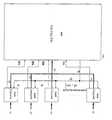
- Figures 1 and 2show the transmission and reception schemes of the method according to the invention.
- the data at different speeds V1, V2, ...Vnarrive separately to the packet collectors-formers RFP1, RFP2.
- ...RFPnin this case formed by buffer stores 1, 2, 3.... n, that are joined by means of the lines L1...Ln and the line in common with the multiplexer MUX.
- the request RQ 1 to the MUXis generated for informing MUX that the packet is available and for having the consent for the transmission thereof.
- the MUXprocesses the request coming from RQ 1 together with the possible other contemporaneous requests coming from RQ 2 to RQn and, if these have not higher priorities than the priority assigned to RQ 1 , it allows the output of the data packet accumulated with speed V1 into the buffer 1.
- the higher prioritycorresponds in the present embodiment to the data concerning the audio, followed by the fixed data of the video part. After these data are transmitted, the codes having a variable length coming from processors and as last data, the data having the lowest speed and importance as the telex transmissions, the ancillary data, etc. are transmitted. These priorities can be changed in any moment.
- MUXEach time the transmission request RQi is recognized, MUX generates the corresponding timings and synchronisms Kl, and SIN:MUX communicates with the circuits forming the packets by means of the lines l 1 , l 2 , li.
- the data transmissionis carried out after having made a redundancy insertion for a future error correction by means of a FEC (Forward Error Corrector).
- FECForward Error Corrector
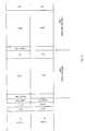
- the definition of the packet type hold in the initial part of the same packetis used as indicated in the Figure 9, that explains how the frame and packets must be formed assigning well-established packet types to each area.
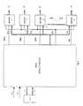
- the output decisionis not taken by the demultiplexer DEMUX in a fixed manner, but it provides said information, after having extracted it from the frame, to an external circuit deciding the destination of the same information PAL, using the bus PT.
- PALdecides in relation to the assignment table supplied case-by-case (that can be changed easily as indicated for the priority RQi) and provides the destination signal of the packet by means of the bus OS.
- the demultiplexer DEMUXdecides the type of synchronism and timings K'1, SIN' that it must generate for the data output; these signals are transmitted onto the lines l'1, l'2 ...l'n, while the information is transmitted onto the lines L'1, L'2...L'n.
- the frameis started with an alignment word of 24 bits, and further 8 bits that is formed by a status word provided by an external system.
- the continuation of the alignment wordis formed by an information of 16 bits, that is the information allowing to recover the video synchronism in reception. All these data are transmitted in the form words of 8 bits even if they can be grouped in words having a greater or shorter length after the buffers.
- mux/demuxIn the case where 34 Mbit/s speed is used, the running of mux/demux is similar to a normal system, excepting the matter that the data transmission is carried out in packets and not according to a fixed sequence.
- the demultiplexingis made revealing the alignment word and, in the moment of the alignment acquisition,the initial heads of the packets are revealed and the information related to the area that must receive the transmitted packet is extracted.
- the dataare multiplexed in MUX, but the series and the line code conversions are applied externally to the circuit in the ECL logics for obvious reasons of work speed; in reception the data enter in DEMUX, already transformed by parallel conversion, directly to the input elastic store and they follow the above said normal process.
- the system according to the inventionallows to use a well established hierarchy for transmitting an information with double speed using two independent flows for the transmission of a sole information. In this manner it can be advantageously used the same type of (doubled) transmission means without the necessity of having an access to other higher means.
- the informationis divided in two flows separating a part from the other part and rejoining these parts in reception for obtaining the original information.
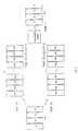
- the Figure 3represents schematically the system according to the invention.
- the word of N bits, Fnis divided in two word of N/2 bits, F1, F'1. Due to the differences in the transmission time TO and the delay changes, the two flows F1 and F'1 arrive with delays DELAY1 and DELAY2, in adddition to the speed changes.
- the information obtained from the time difference at the apparition of the alignment wordis used as an indication of the difference between the transmission times of the two flows.
- a channel C1transmits the N/2 bits of greater weight of the word of N bits and the second channel C2 transmits the other N/2 bits of less weight (e.g. see Figure 1).
- the following factorsmust be considered:
- This second possibilityrequires the introduction of an alignment word revelation different in each channel, generating a high or low channel indication. In this manner/the input channel changes are compensated automatically.
- Figure 4shows the input flows F1, F1', that are now introduced into an elastic store ME with different clocks.
- the name of elastic storemeans that it is a store where the reading-writing distance is variable, the data being introduced by means of a clock and the data being read by means of a second clock.
- the aim of a memory of this typeis to absorb the instantaneous changes of the writing clock and further, in the present embodiment, to synchronize the bits, as the writing uses a clock for each flow, while the reading uses a same master clock in the two memories.
- a PLLmust be used for getting that the writing arid reading frequencies are equal, for avoiding fillings and emptyings of the elastic store ME, that, as stated above, must absorb the instantaneous changes. Therefore the output of the elastic store provides two synchronized information along the duration of bits, read in the two flows by the same clock, as it is shown in Figure 4. Therefore a synchronization at clock level and a new alignment at bit level is obtained.
- Each of information(packets PA11...PA21; respectively PA12..PA22) is transmitted to an alignment detector that provides the words correctly aligned and formed as they were originally, due to the detecting of the alignment word, and so the right bit for each word being started can be known. Therefore at the input of the alignment generator RI, as shown in Figure 5, two flows can be got (represented by the continuous line) that must be aligned correctly.
- the wordsare aligned correctly at output, but it exists a time difference between the apparition of the alignment words in each flow. This difference supplies the mean value of the delay between the two frames that is compensated. Until this moment the word synchronism is got.
- one flowmust be defined as master flow and the other flow as slave flow.
- the master flowis the flow that was joined to the circuit clock frequency.
- the difference between the apparition of the alignment words in the secondary flowcan be positive or negative with respect to the master flow, i.e. it can be in advance or delay. In other words, the time difference can be positive or negative.
- the time difference between the apparition of two alignment wordsis revealed. This difference must be compensated. To do this, the master flow is always delayed of a fixed value T, so that the alignment word appears always at output shifted by T words after the detecting thereof.
- the slave flowcan be shifted in advance or in delay with respect to the other flow.
- the alignment detectorstarts a counter for each of the flows.
- the time difference between the two channelsis given by the difference between two counters CNT1-CNT2 (CNT1 - counter of the master channel, CNT2 - counter of the slave channel). This value can be positive or negative, according to whether the alignment word appeared in master channel or in slave channel for the first time.
- the master flowwas delayed of a fixed value T, therefore, at the instant t01, the alignment word appears in the master channel and in the instant t02, the same word appears in the slave channel.
- the second optionis used, whose implementation is easier .
- a representation of the embodiment forms of the two optionsis visible in Figures 7 and 8 respectively.
- the frame synchronismis obtained, by which, always considering that the delay difference between the two frames is lower than the fixed value, the two channels can be completely synchronized. In the case in which it is not possible to compensate the delay, it is generated an external alarm.
- Another performance carried out by the circuitis the possibility of working as a "repeater” introducing directly the data from another demultiplexer and using an external selection to replace the packets that are required in the point of the distribution network and inserting further the supplementary information in the packets that in transmission were let free just for realizing this possibility, as indicated above.
- the frameis really formed by two packets PAC1, PAC2 of 255 words formed each of 16 bits; the head of each packet uses two words of 16 bits reserved to the alignment words (24 bits) ALIN1, ALIN2, ALIN3, and to the status word (STATUS) (8 bits) and further two 16 bit words for the video synchronism (VIDEO FREC).
- Each packetis protected by an error correction code (FEC).
- FECerror correction code
- the first 16 bits of each packethold the information related to the source from which the same packet comes (PACKET TYPE).
- the transmissidn from the buffer store Bi to the multiplexer MUX and from the demultiplexer DEMUX to the buffer B'ioccurs by means of the 8 bit words (P1, P2).
- the multiplexercan run with three different speeds: 1 flow with 34 Mb/s; 2 flows with 34 Mb/s; 1 flow with 140 Mb/s.
- all of operations of a multiplexer-demultiplexerare advantageously made internally to the semicustom circuit, while in the third case the series/parallel conversion and the interface of lines are carried out externally by ECL logics due to the very high speed.
- the transmission speed of 34 Mb/sis used on two independent flows.
- the two flowsare joined in reception in a correct manner, synchronizing the two input flows.
- the 8 bit words in transmissionare divided in two 4 bit words (the most significant 4 sits and the less significant 4 bits), and transmitted independently. In reception it is possible to recognize the most significant bits and the less significant bits (as it is necessary to recognize different alignment words) being possible, in this manner, to compensate eventual channel exchanges.
- the two received flowsare recorded in two elastic stores with different writing clocks extracted from flows and are read with the same clock, that is the one related to the master flow ( Figure 4).
- an alignment generator RI( Figure 5) is presented in each path and at output from each alignment generator a correctly aligned flow is obtained; as a time difference between the position of the alignment word can be present in a flow with respect to the other flow, it is compensated from the variable delay line SC ( Figure 6) so that, in the preferred embodiment of Figure 8, registers are inserted by means of MUX.
- the systemcan run as repeater, in which case the free packets are replaced with the desired packets.
Landscapes
- Engineering & Computer Science (AREA)
- Multimedia (AREA)
- Signal Processing (AREA)
- Time-Division Multiplex Systems (AREA)
- Data Exchanges In Wide-Area Networks (AREA)
- Details Of Television Systems (AREA)
- Color Television Systems (AREA)
- Television Systems (AREA)
- Processing Of Color Television Signals (AREA)
- Compression Or Coding Systems Of Tv Signals (AREA)
Description
- The present invention relates to a method and a system for the transmission/reception of digital television information (video + audio), in particular for the high definition television information (HDTV).
- The multiplexing/demultiplexing systems usually order the data in transmission at a fixed distance in the frame and separate the data in reception according to this preestablished sequence. In the case where the data must be transmitted at different speeds, the operations become more complex and the classic system cannot be used. So, there is a problem, due to the necessity of transmitting data series with different speeds. Moreover until to by, for increasing the data speed to be transmitted by a system, a higher data hierarchy was used with the following necessity of using transmission means having a higher frequency.
- From Signal Processing of HDTV, II; Proc. of the 3rd International Workshop on HDTV, Turin, 30-09-1989; pages 587-594; M.Barbero et al.: "A flexible architecture for HDTV codec based on DCT", a method including the features of the first part of
claim 1 and a system including the features of the first part of claim 7 are known. - Further, Globecom '85 - IEEE Global Telecommunications Conference, New Orleans, 2-5 Dec. 1985; vol. 1, pages 1251-1255; L.Chiariglione et al.: "Multimedia Communication at the basic ISDN access"; discloses a realignment of data packets belonging to the same signal on the reception side by using a frame synchronisation signal. A realignment of data packets on the reception side is also described in Globecom '85; 2-12-1985; vol. 3/3, pages 1340-1344; L. Chiariglione et al.: "A family of frame structures for local video distribution", and IEEE Journal on Selected Areas of Telecommunications, vol. 7 n.5, June 1989; pages 739-751; G.Karlsson et al.: "Packet video and its integration into the network architecture".
- The object of the present invention is to provide a simple and efficient method for high speed transmission of signals with different speeds and a system suitable to implement such a method.
- This object is met by a method according to
claim 1 and a system according to claim 7. Preferred embodiments are disclosed in the depending claims. The system according to the invention allows to use a well established hierarchy for transmitting an information with double speed using two independent flows for the transmission of a sole information. In this manner it can be advantageously used the same type of transmission means without the necessity of having an access to other higher means. - According to the invention the data at different speeds are no more transmitted unchanged directly to the multiplexing stage, but they are collected externally to the multiplexer in packet forming means of preestablished structure; each time said means have formed a packet they send a request to the multiplexing stage. The different sources are supplied with different priorities, therefore, in the case of contemporaneous transmission requests, the request coming from the packet source that is associated to higher priority is satisfied first.
- Fig. 1 is a block diagram of the transmission circuitry of the present invention;
- Fig. 2 is a block diagram of the reception circuitry of the present invention;
- Fig. 3 shows the transmission of words having a length of N bits divided into two paths with words having a length of N/2 bits;
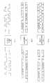
- Fig. 4 shows the elastic store that carries out the new alignment at bit level and the synchronisation at clock level;
- Fig. 5 shows the alignment generator;
- Fig. 6 shows the delay compensation;
- Fig. 7 shows a conventional variable delay line for providing the delay compensation of Fig. 6;
- Fig. 8 shows a delay line formed of a series of multiplexers preceded by shift registers for providing the delay compensation of Fig. 6; and
- Fig. 9 shows an example of the contents of two packets.
- Figures 1 and 2 show the transmission and reception schemes of the method according to the invention. The data at different speeds V1, V2, ...Vn arrive separately to the packet collectors-formers RFP1, RFP2....RFPn, in this case formed by
buffer stores buffer 1. The higher priority corresponds in the present embodiment to the data concerning the audio, followed by the fixed data of the video part. After these data are transmitted, the codes having a variable length coming from processors and as last data, the data having the lowest speed and importance as the telex transmissions, the ancillary data, etc. are transmitted. These priorities can be changed in any moment. Each time the transmission request RQi is recognized, MUX generates the corresponding timings and synchronisms Kl, and SIN:MUX communicates with the circuits forming the packets by means of the lines l1, l2, li. - The data transmission is carried out after having made a redundancy insertion for a future error correction by means of a FEC (Forward Error Corrector).
- In reception (Figure 2) the circuit must recognize the buffer 1', 2'... n' to which each received packet is destined.
- For making this, the definition of the packet type hold in the initial part of the same packet is used as indicated in the Figure 9, that explains how the frame and packets must be formed assigning well-established packet types to each area. For allowing the changing and programming of this information according to the future requirements of the total system, the output decision is not taken by the demultiplexer DEMUX in a fixed manner, but it provides said information, after having extracted it from the frame, to an external circuit deciding the destination of the same information PAL, using the bus PT. PAL decides in relation to the assignment table supplied case-by-case (that can be changed easily as indicated for the priority RQi) and provides the destination signal of the packet by means of the bus OS.
- Depending on the information sent by OS, the demultiplexer DEMUX decides the type of synchronism and timings K'1, SIN' that it must generate for the data output; these signals are transmitted onto the lines l'1, l'2 ...l'n, while the information is transmitted onto the lines L'1, L'2...L'n.
- As data output speeds and according to the quantity of information to be transmitted, the following channel speeds are used:
- 1 channel with 34 Mbits/s
- 2 channels with 34 Mbits/s
- 1 channel with 140 Mbits/s
- The higher the speed, the better the signal quality that can be transmitted in the same transmission time interval.
- Considering the first two cases, all multiplexing/demultiplexing part is processed in the semicustom circuit, and considering the last case, due to the high speed of the final stages, the series-parallel or parallel-series conversions and the interfaces of the lines are done externally using ECL logics. The information distribution is based on frames (Figure 9) formed by two data packets having 238 words of 16 bits, and further a first head word that holds the above mentioned definition of the packet type in the first 8 bits, said information being protected by a Hamming code, error corrector, and further 16 redundancy words of 16 bits for the error correction.
- The frame is started with an alignment word of 24 bits, and further 8 bits that is formed by a status word provided by an external system.
- The continuation of the alignment word is formed by an information of 16 bits, that is the information allowing to recover the video synchronism in reception. All these data are transmitted in the form words of 8 bits even if they can be grouped in words having a greater or shorter length after the buffers.
- In the case where 34 Mbit/s speed is used, the running of mux/demux is similar to a normal system, excepting the matter that the data transmission is carried out in packets and not according to a fixed sequence. The demultiplexing is made revealing the alignment word and, in the moment of the alignment acquisition,the initial heads of the packets are revealed and the information related to the area that must receive the transmitted packet is extracted.
- In the case where 140 Mbit/s speed is used, the data are multiplexed in MUX, but the series and the line code conversions are applied externally to the circuit in the ECL logics for obvious reasons of work speed; in reception the data enter in DEMUX, already transformed by parallel conversion, directly to the input elastic store and they follow the above said normal process.
- The more interesting part is that related to 2*34 Mbits/s, in which two independent channels C1, C2 (respectively C'1, C'2) are used for transmitting the whole information. Until today, for increasing the data speed to be transmitted by a system, a higher data hierarchy was used with the following necessity of using a transmission means having a higher frequency. This fact requires to use, e.g. in the case of radiocommunications, higher and higher channels with consequent problems of the increasing frequency, included in the microwave field.
- In the present embodiment a speed of 2x34 Mbit/s with 8 bits words is advantageously used, but the following explanation refers to a generical system.
- The system according to the invention allows to use a well established hierarchy for transmitting an information with double speed using two independent flows for the transmission of a sole information. In this manner it can be advantageously used the same type of (doubled) transmission means without the necessity of having an access to other higher means.
- According to a feature of the invention, the information is divided in two flows separating a part from the other part and rejoining these parts in reception for obtaining the original information. For acting in this manner, it is necessary to synchronize the two independent flows and compensate the time differences between the flows for the different delays to which they are submitted due to the differences in the transmission means.
- The Figure 3 represents schematically the system according to the invention. In transmission the word of N bits, Fn , is divided in two word of N/2 bits, F1, F'1. Due to the differences in the transmission time TO and the delay changes, the two flows F1 and F'1 arrive with delays DELAY1 and DELAY2, in adddition to the speed changes.
- In reception these changes must be compensated for turning to the original words of N bits.
- According to a feature of the invention, as an indication of the difference between the transmission times of the two flows, the information obtained from the time difference at the apparition of the alignment word is used.
- In transmission a channel C1 transmits the N/2 bits of greater weight of the word of N bits and the second channel C2 transmits the other N/2 bits of less weight (e.g. see Figure 1). In reception the following factors must be considered:
- each channel has different delays for being independent, therefore the time differences between the two information must be compensated, as stated above;
- as a further performance a revelation of the channel fixing each information can be added.
- This second possibility requires the introduction of an alignment word revelation different in each channel, generating a high or low channel indication. In this manner/the input channel changes are compensated automatically.
- For compensating the delay, a more complex process is applied that can be understood better with reference to the Figures 4, 5 and 6.
- Figure 4 shows the input flows F1, F1', that are now introduced into an elastic store ME with different clocks. The name of elastic store means that it is a store where the reading-writing distance is variable, the data being introduced by means of a clock and the data being read by means of a second clock.
- The aim of a memory of this type is to absorb the instantaneous changes of the writing clock and further, in the present embodiment, to synchronize the bits, as the writing uses a clock for each flow, while the reading uses a same master clock in the two memories. Obviously a PLL must be used for getting that the writing arid reading frequencies are equal, for avoiding fillings and emptyings of the elastic store ME, that, as stated above, must absorb the instantaneous changes. Therefore the output of the elastic store provides two synchronized information along the duration of bits, read in the two flows by the same clock, as it is shown in Figure 4. Therefore a synchronization at clock level and a new alignment at bit level is obtained. Each of information (packets PA11...PA21; respectively PA12..PA22) is transmitted to an alignment detector that provides the words correctly aligned and formed as they were originally, due to the detecting of the alignment word, and so the right bit for each word being started can be known. Therefore at the input of the alignment generator RI, as shown in Figure 5, two flows can be got (represented by the continuous line) that must be aligned correctly.
- The words are aligned correctly at output, but it exists a time difference between the apparition of the alignment words in each flow. This difference supplies the mean value of the delay between the two frames that is compensated. Until this moment the word synchronism is got.
- For understanding as the time difference is compensated, one flow must be defined as master flow and the other flow as slave flow. The master flow is the flow that was joined to the circuit clock frequency. The difference between the apparition of the alignment words in the secondary flow can be positive or negative with respect to the master flow, i.e. it can be in advance or delay. In other words, the time difference can be positive or negative. The time difference between the apparition of two alignment words is revealed. This difference must be compensated. To do this, the master flow is always delayed of a fixed value T, so that the alignment word appears always at output shifted by T words after the detecting thereof.
- The slave flow can be shifted in advance or in delay with respect to the other flow. For discovering this, the alignment detector starts a counter for each of the flows. At the moment in which the alignment word appears in the two channels, the time difference between the two channels is given by the difference between two counters CNT1-CNT2 (CNT1 - counter of the master channel, CNT2 - counter of the slave channel). This value can be positive or negative, according to whether the alignment word appeared in master channel or in slave channel for the first time.
- This value is named D, so that:

- As stated above, the master flow was delayed of a fixed value T, therefore, at the instant t01, the alignment word appears in the master channel and in the instant t02, the same word appears in the slave channel. The difference between the two times shall be:

- The alignment word after the delay appears at the time t0t1, given by the expression:

- The slave channel includes a delay TS that provides the output at the instant t0t2, given by:

- The solution that it looked for is that t0t1 = t0t2, from which:replacing [1]:


- Therefore a variable delay line is used, in which it is assumed that the minimum value of TS = 0, (to delay the signal of a negative number shall be equivalent to accelerate it), therefore:

from which:
0 < TS < 2T; - In the present embodiment, the value of T was selected equal to 64 therefore, as words are treated, a delay of 64*4 bit = 256 bit is presented; TS being variable between 0 and 512 bit, that in the case of 2*34 Mbit/s provides time of bit equal to 1/34 µs and a delay compensation of 256*1/34,368 µs = 7.5 µs in advance or delay.
- Comparing this value of total frame time, that should have a length (always for our particular application):


- Expressing the compensation in other manner, it can be seen as:

- The embodiment of the variable delay line allows two variants:
- a memory in which the reading-writing distance fixes the delay thereof;
- a shift register line, forming the delays of 2^ N and selecting the delay to be applied by means of a multiplexer selection.
- As preferred embodiment the second option is used, whose implementation is easier .A representation of the embodiment forms of the two options is visible in Figures 7 and 8 respectively.
- At the output of the delay lines the frame synchronism is obtained, by which, always considering that the delay difference between the two frames is lower than the fixed value, the two channels can be completely synchronized. In the case in which it is not possible to compensate the delay, it is generated an external alarm.
- This alarm must indicate only that the absolute value of D is higher than the maximum foreseen value.
- As it can be noticed in the Figure 6, at output of the system SC of delay compensation, the two frames are completely synchronized and the sole action that must be done is to join the two words of N/2 bits in words of N bits for reconstructing the original information.
- Another performance carried out by the circuit is the possibility of working as a "repeater" introducing directly the data from another demultiplexer and using an external selection to replace the packets that are required in the point of the distribution network and inserting further the supplementary information in the packets that in transmission were let free just for realizing this possibility, as indicated above.
- This is obtained by means of the data introduction by another bus and, in the case of revelation of a "replaceable" packet with one of the packets fixed externally is replaced.
- For better explanation:
- Figure 3 shows the flow fu formed by words having a N length, that at the time TO is divided in two flows F1 and F1' having words of N/2 length. F1 arrives to the demultiplexer DEMUX at the moment TO +
delay 1, F'1 arrives AT TO +delay 2; DEMUX joins again F1 and F'2 compensating therespective delays - Figure 4 represents the elastic store ME that carries out the new alignment at bit level between F1 and F2 and the synchronization at clock level;
- Figure 5 represents the tester RI of synchronzation and therefore at word level;
- Figure 6 shows the compensation system with new alignment at packet level;
- Figure 7 represents the variable delay line (for compensating the delay of Figure 6) made with classic system, that is a store that receives the data in input IN and sends them at output OUT with a delay that is equal to the distance between reading and writing; for this aim the writing is controlled by the counter WC, whose counting, added with the delay TS, controls the reading;
- Figure 8 shows the delay line that is advantageously formed by a series of MUX preceded by registers that supply shifts 2∧N, 2∧(N-1)...respectively 1. The first MUX receives the signal at input IN, the signal from the register with shift 2∧N and the signal of a LATCH fed by the delay signal TS. Each of MUXs following the first MUX shall receive the signals from the preceding MUX, from the decreasing shift register 2∧(N-1) etc. and from the LATCH;
- Figure 9 shows the formation scheme of two exemplifying packets (first, second packet PAC1, PAC2).
- In a particularly simple and advantageous embodiment the frame is really formed by two packets PAC1, PAC2 of 255 words formed each of 16 bits; the head of each packet uses two words of 16 bits reserved to the alignment words (24 bits) ALIN1, ALIN2, ALIN3, and to the status word (STATUS) (8 bits) and further two 16 bit words for the video synchronism (VIDEO FREC). Each packet is protected by an error correction code (FEC). The first 16 bits of each packet hold the information related to the source from which the same packet comes (PACKET TYPE). The transmissidn from the buffer store Bi to the multiplexer MUX and from the demultiplexer DEMUX to the buffer B'i occurs by means of the 8 bit words (P1, P2). It was stated above that the multiplexer can run with three different speeds: 1 flow with 34 Mb/s; 2 flows with 34 Mb/s; 1 flow with 140 Mb/s. In the first two cases all of operations of a multiplexer-demultiplexer are advantageously made internally to the semicustom circuit, while in the third case the series/parallel conversion and the interface of lines are carried out externally by ECL logics due to the very high speed. In the
case 2 flows with 34 Mb/s are used, the advantage of working with a frequency double of 34 Mb/s is obtained, the transmission speed of 34 Mb/s is used on two independent flows. - For getting the original information, the two flows are joined in reception in a correct manner, synchronizing the two input flows. The 8 bit words in transmission are divided in two 4 bit words (the most significant 4 sits and the less significant 4 bits), and transmitted independently. In reception it is possible to recognize the most significant bits and the less significant bits (as it is necessary to recognize different alignment words) being possible, in this manner, to compensate eventual channel exchanges. The two received flows are recorded in two elastic stores with different writing clocks extracted from flows and are read with the same clock, that is the one related to the master flow (Figure 4). Then an alignment generator RI (Figure 5) is presented in each path and at output from each alignment generator a correctly aligned flow is obtained; as a time difference between the position of the alignment word can be present in a flow with respect to the other flow, it is compensated from the variable delay line SC (Figure 6) so that, in the preferred embodiment of Figure 8, registers are inserted by means of MUX.
- As stated above, the system can run as repeater, in which case the free packets are replaced with the desired packets.


Claims (11)
- A method for the transmission and reception of video, audio and data signals, said signals being digital signals coming from different sources and having speeds different with one another,wherein in transmissioneach of said signals is accumulated into one of a plurality of buffers (1, ..., n) so as to form respective packets, and when a packet is ready the respective buffer requires a multiplexer (MUX) to transmit said packet, said multiplexer fulfilling the requestsaccording to a predetermined priority order, andwherein in receptionthe packets are distributed by a demultiplexer (DEMUX) to one of a plurality of buffers (1', ..., n'), and then to the related receivers,characterised in thatin transmission the information to be transmitted is supplemented with alignment words and is divided into two flows, wherein said two flows are transmitted on two independent channels (C'1, C'2), andin reception said two flows are received and joined together by the steps of writing said two received flows into two elastic stores (ME) with two different writing clocks extracted from said two flows, reading said two flows from said two elastic stores (ME) with the same reading clock, and aligning said two flows read out of said elastic stores on the basis of said alignment words.
- The method according to claim 1, wherein the difference between the transmission times of the two flows received on said two channels (C'1, C'2) is compensated on the basis of the time difference between the detection of said alignment words in each flow.
- The method according to claim 2, wherein said compensation is carried out by defining the flow received on one channel as master flow and the flow received on the other channel as slave flow, by delaying said master flow with a fixed value and by delaying said slave flow with a variable value so that the alignment words of said two flows appear at the same time.
- The method according to claim 2 or 3, wherein, when said compensation of the difference between the transmission times is not possible, and external alarm is generated.
- The method according to any of claims 1 to 4, wherein said two flows are transmitted at a rate of 34 Mbit/s each.
- The method according to any of claims 1 to 5, wherein some packets are replaced by packets from another demultiplexer.
- A system for the transmission and reception of video, audio and data signals, said signals being digital signals coming from different sources and having speeds different with one another,comprising in transmissionmeans (V1, V2, ..., Vn) for feeding said signals to means (1, ..., n) for forming packets,means for assigning a predetermined priority to said means (1, ..., n) for forming packets,a multiplexer (MUX) for multiplexing and transmitting said packets, andmeans (RQ1, ..., Rqn) for requiring said multiplexer (MUX) to transmit a packet when the packet is ready, said multiplexer fulfilling the requests according to said predetermined priority order,and comprising in receptiona demultiplexer (DEMUX) for distributing each packet to one of a plurality of buffers (1', ..., n'), and then to the related receivers,characterised bymeans for supplementing the information to be transmitted with alignment words, and for dividing said information to be transmitted into two flows,two independent channels (C'1, C'2) for transmitting said two flows from said multiplexer (MUX) to said demultiplexer (DEMUX), andmeans for receiving and joining together said two flows, said means including elastic store means (ME) for writing in said two received flows with two different writing clocks extracted from said two flows, and for reading out said two flows with the same reading clock, and alignment generating means (RI) for aligning said two flows read out of said elastic store means on the basis of said alignment words.
- The system according to claim 7, further comprising compensation means (SC) for compensating the difference between the transmission times of the two flows received on said two channels (C'1, C'2) on the basis of the time difference between the detection of said alignment words in each flow.
- The system according to claim 8, wherein said compensation means (SC) includes a variable delay line for each flow preferably formed by many registers and multiplexers and one latch.
- The system according to any of claims 7 to 9, wherein said means for forming packets is a series of buffers.
- The system according to any of claims 7 to 10, wherein said demultiplexer (DEMUX) is associated to a circuit (PAL) for packet decision and destination.
Applications Claiming Priority (2)
| Application Number | Priority Date | Filing Date | Title |
|---|---|---|---|
| IT02223089AIT1237668B (en) | 1989-10-31 | 1989-10-31 | SYSTEM AND MULTIPLATOR / DEMULTIPLATOR FOR THE TRANSMISSION / RECEPTION OF DIGITAL TELEVISION INFORMATION. |
| IT2223089 | 1989-10-31 |
Publications (3)
| Publication Number | Publication Date |
|---|---|
| EP0425834A2 EP0425834A2 (en) | 1991-05-08 |
| EP0425834A3 EP0425834A3 (en) | 1993-02-17 |
| EP0425834B1true EP0425834B1 (en) | 1997-03-19 |
Family
ID=11193388
Family Applications (1)
| Application Number | Title | Priority Date | Filing Date |
|---|---|---|---|
| EP90119038AExpired - LifetimeEP0425834B1 (en) | 1989-10-31 | 1990-10-04 | System and multiplexer/ demultiplexer for the transmission/ reception of digital television information |
Country Status (5)
| Country | Link |
|---|---|
| US (1) | US5202886A (en) |
| EP (1) | EP0425834B1 (en) |
| JP (1) | JP3337212B2 (en) |
| DE (1) | DE69030235T2 (en) |
| IT (1) | IT1237668B (en) |
Cited By (17)
| Publication number | Priority date | Publication date | Assignee | Title |
|---|---|---|---|---|
| US6539548B1 (en) | 1992-12-09 | 2003-03-25 | Discovery Communications, Inc. | Operations center for a television program packaging and delivery system |
| US7017178B1 (en) | 1992-12-09 | 2006-03-21 | Sedna Patent Services, Llc | Audio program reception terminal for television delivery system |
| US7073187B1 (en) | 1992-12-09 | 2006-07-04 | Sedna Patent Services, Llc | Menu-driven television program access system and method |
| US7207055B1 (en) | 1992-12-09 | 2007-04-17 | Sedna Patent Services, Llc | Bandwidth allocation for a television program delivery system |
| US7269841B1 (en) | 1992-12-09 | 2007-09-11 | Sedna Patent Services, Llc | Digital cable headend for cable television delivery system |
| US7336788B1 (en) | 1992-12-09 | 2008-02-26 | Discovery Communicatoins Inc. | Electronic book secure communication with home subsystem |
| US7401286B1 (en) | 1993-12-02 | 2008-07-15 | Discovery Communications, Inc. | Electronic book electronic links |
| US7509270B1 (en) | 1992-12-09 | 2009-03-24 | Discovery Communications, Inc. | Electronic Book having electronic commerce features |
| US7590993B1 (en) | 1992-12-09 | 2009-09-15 | Comcast Ip Holdings I, Llc | Method and apparatus for gathering programs watched data |
| US7835989B1 (en) | 1992-12-09 | 2010-11-16 | Discovery Communications, Inc. | Electronic book alternative delivery systems |
| US7849393B1 (en) | 1992-12-09 | 2010-12-07 | Discovery Communications, Inc. | Electronic book connection to world watch live |
| US7861166B1 (en) | 1993-12-02 | 2010-12-28 | Discovery Patent Holding, Llc | Resizing document pages to fit available hardware screens |
| US7865567B1 (en) | 1993-12-02 | 2011-01-04 | Discovery Patent Holdings, Llc | Virtual on-demand electronic book |
| US8073695B1 (en) | 1992-12-09 | 2011-12-06 | Adrea, LLC | Electronic book with voice emulation features |
| US8095949B1 (en) | 1993-12-02 | 2012-01-10 | Adrea, LLC | Electronic book with restricted access features |
| US9009773B1 (en) | 1998-06-30 | 2015-04-14 | Cox Communications, Inc. | Method and apparatus for providing broadcast data services |
| US9053640B1 (en) | 1993-12-02 | 2015-06-09 | Adrea, LLC | Interactive electronic book |
Families Citing this family (33)
| Publication number | Priority date | Publication date | Assignee | Title |
|---|---|---|---|---|
| JPH0575651A (en)* | 1991-09-13 | 1993-03-26 | Nec Corp | Packet transmission system |
| FR2690805B1 (en)* | 1992-05-04 | 1995-11-24 | Matra Communication | DEVICE FOR INSERTING DIGITAL TELEVISION PROGRAMS ON A TRANSMISSION OR BROADCAST CHANNEL AND DEVICE FOR RECEIVING SUCH PROGRAMS. |
| JP2682334B2 (en)* | 1992-05-29 | 1997-11-26 | 日本電気株式会社 | Image signal coding transmission method |
| EP0576856A3 (en)* | 1992-06-30 | 1996-07-03 | Siemens Ag | Method and circuit for transmission of a continuous atm bitstream |
| US5388101A (en)* | 1992-10-26 | 1995-02-07 | Eon Corporation | Interactive nationwide data service communication system for stationary and mobile battery operated subscriber units |
| JP3076462B2 (en)* | 1992-11-09 | 2000-08-14 | 松下電器産業株式会社 | Versatile variable length coder for digital video coder |
| JP3002348B2 (en)* | 1992-11-30 | 2000-01-24 | シャープ株式会社 | Image communication system |
| US9286294B2 (en) | 1992-12-09 | 2016-03-15 | Comcast Ip Holdings I, Llc | Video and digital multimedia aggregator content suggestion engine |
| US7168084B1 (en) | 1992-12-09 | 2007-01-23 | Sedna Patent Services, Llc | Method and apparatus for targeting virtual objects |
| US5412426A (en)* | 1993-04-16 | 1995-05-02 | Harris Corporation | Multiplexing of digitally encoded NTSC and HDTV signals over single microwave communication link from television studio to tower transmitter facility for simultaneous broadcast (simulcast) to customer sites by transmitter facility |
| US5486864A (en)* | 1993-05-13 | 1996-01-23 | Rca Thomson Licensing Corporation | Differential time code method and apparatus as for a compressed video signal |
| KR100306686B1 (en)* | 1993-09-10 | 2001-11-30 | 에릭 피. 헤르만 | Real-Time Audio Packet Layer Encoder |
| JP3149303B2 (en)* | 1993-12-29 | 2001-03-26 | 松下電器産業株式会社 | Digital image encoding method and digital image decoding method |
| KR960008470B1 (en)* | 1994-01-18 | 1996-06-26 | Daewoo Electronics Co Ltd | Apparatus for transferring bit stream data adaptively in the moving picture |
| AU6816094A (en)* | 1994-04-20 | 1995-11-16 | Thomson Consumer Electronics, Inc | A multiplexer system using constant bit rate encoders |
| US6055270A (en)* | 1994-04-20 | 2000-04-25 | Thomson Cosumer Electronics, Inc. | Multiplexer system using constant bit rate encoders |
| US5521979A (en)* | 1994-04-22 | 1996-05-28 | Thomson Consumer Electronics, Inc. | Packet video signal inverse transport system |
| DE4415288A1 (en)* | 1994-04-30 | 1995-11-02 | Ant Nachrichtentech | Process for the preparation and recovery of data and arrangement therefor |
| CA2199815C (en)* | 1994-09-12 | 2001-07-24 | Catherine W. Jelinek | Cable television apparatus employing two-way communication |
| US5481312A (en)* | 1994-09-12 | 1996-01-02 | At&T Corp. | Method of and apparatus for the transmission of high and low priority segments of a video bitstream over packet networks |
| KR100188084B1 (en)* | 1995-05-12 | 1999-06-01 | 김광호 | Apparatus and method for transmitting audio data using video signal line |
| US5574505A (en)* | 1995-05-16 | 1996-11-12 | Thomson Multimedia S.A. | Method and apparatus for operating a transport stream encoder to produce a stream of packets carrying data representing a plurality of component signals |
| US5621463A (en)* | 1995-05-16 | 1997-04-15 | Thomson Multimedia S.A. | Easily expandable transport stream encoder |
| US5598413A (en)* | 1995-07-10 | 1997-01-28 | Adtran, Inc. | Four-wire, half-rate architecture with embedded differential delay compensation for extending range of basic rate ISDN communications |
| US5729292A (en)* | 1995-12-21 | 1998-03-17 | Thomson Multimedia, S.A. | Optimizing performance in a packet slot priority packet transport system |
| EP0826289B1 (en) | 1996-03-19 | 2002-10-16 | Sony Corporation | Data multiplexing apparatus |
| EP0985320B1 (en) | 1998-03-26 | 2007-08-29 | Earth View Television & Datatransfer GmbH | Device for multiplexing video signals |
| FR2815805B1 (en)* | 2000-10-23 | 2005-09-02 | Telediffusion De France Tdf | METHOD FOR SYNCHRONIZING DIGITAL SIGNALS |
| US7793326B2 (en) | 2001-08-03 | 2010-09-07 | Comcast Ip Holdings I, Llc | Video and digital multimedia aggregator |
| US7908628B2 (en) | 2001-08-03 | 2011-03-15 | Comcast Ip Holdings I, Llc | Video and digital multimedia aggregator content coding and formatting |
| FR2830158B1 (en)* | 2001-09-24 | 2004-09-10 | Telediffusion De France Tdf | DEVICE FOR TRANSMITTING MULTIPLE DIGITAL SIGNALS ON A SINGLE TRANSMISSION MEDIUM |
| KR100866182B1 (en)* | 2001-12-04 | 2008-10-30 | 삼성전자주식회사 | Apparatus and method for data transmission in mobile communication system |
| US7080305B2 (en)* | 2002-12-23 | 2006-07-18 | Sun Microsystems, Inc. | System and method for correcting data errors |
Family Cites Families (6)
| Publication number | Priority date | Publication date | Assignee | Title |
|---|---|---|---|---|
| US4045618A (en)* | 1976-01-29 | 1977-08-30 | Compagnie Industrielle Des Telecommunications Cit-Alcatel S.A. | Device for synchronizing a binary data train in relation to a reference train |
| FR2545670B1 (en)* | 1983-05-04 | 1985-07-05 | Billy Jean Claude | MULTIPLEXER, DEMULTIPLEXER AND MULTIPLEXING-DEMULTIPLEXING EQUIPMENT WITH RECONFIGURABLE FRAMES |
| JPS63276795A (en)* | 1986-12-16 | 1988-11-15 | Mitsubishi Electric Corp | Variable length shift register |
| FR2629972A1 (en)* | 1988-04-08 | 1989-10-13 | Thomson Csf | Device and method for managing priority |
| US4939723A (en)* | 1989-06-07 | 1990-07-03 | Ford Aerospace Corporation | Bit-channel multiplexer/demultiplexer |
| US5048013A (en)* | 1990-04-06 | 1991-09-10 | At&T Bell Laboratories | Transmission congestion control method and apparatus |
- 1989
- 1989-10-31ITIT02223089Apatent/IT1237668B/enactiveIP Right Grant
- 1990
- 1990-10-04DEDE69030235Tpatent/DE69030235T2/ennot_activeExpired - Lifetime
- 1990-10-04EPEP90119038Apatent/EP0425834B1/ennot_activeExpired - Lifetime
- 1990-10-30JPJP29098290Apatent/JP3337212B2/ennot_activeExpired - Lifetime
- 1990-10-30USUS07/605,969patent/US5202886A/ennot_activeExpired - Lifetime
Cited By (21)
| Publication number | Priority date | Publication date | Assignee | Title |
|---|---|---|---|---|
| US7835989B1 (en) | 1992-12-09 | 2010-11-16 | Discovery Communications, Inc. | Electronic book alternative delivery systems |
| US7865405B2 (en) | 1992-12-09 | 2011-01-04 | Discovery Patent Holdings, Llc | Electronic book having electronic commerce features |
| US7073187B1 (en) | 1992-12-09 | 2006-07-04 | Sedna Patent Services, Llc | Menu-driven television program access system and method |
| US7207055B1 (en) | 1992-12-09 | 2007-04-17 | Sedna Patent Services, Llc | Bandwidth allocation for a television program delivery system |
| US7269841B1 (en) | 1992-12-09 | 2007-09-11 | Sedna Patent Services, Llc | Digital cable headend for cable television delivery system |
| US7336788B1 (en) | 1992-12-09 | 2008-02-26 | Discovery Communicatoins Inc. | Electronic book secure communication with home subsystem |
| US8073695B1 (en) | 1992-12-09 | 2011-12-06 | Adrea, LLC | Electronic book with voice emulation features |
| US7509270B1 (en) | 1992-12-09 | 2009-03-24 | Discovery Communications, Inc. | Electronic Book having electronic commerce features |
| US7590993B1 (en) | 1992-12-09 | 2009-09-15 | Comcast Ip Holdings I, Llc | Method and apparatus for gathering programs watched data |
| US7716349B1 (en) | 1992-12-09 | 2010-05-11 | Discovery Communications, Inc. | Electronic book library/bookstore system |
| US7017178B1 (en) | 1992-12-09 | 2006-03-21 | Sedna Patent Services, Llc | Audio program reception terminal for television delivery system |
| US7849393B1 (en) | 1992-12-09 | 2010-12-07 | Discovery Communications, Inc. | Electronic book connection to world watch live |
| US6539548B1 (en) | 1992-12-09 | 2003-03-25 | Discovery Communications, Inc. | Operations center for a television program packaging and delivery system |
| US7401286B1 (en) | 1993-12-02 | 2008-07-15 | Discovery Communications, Inc. | Electronic book electronic links |
| US7865567B1 (en) | 1993-12-02 | 2011-01-04 | Discovery Patent Holdings, Llc | Virtual on-demand electronic book |
| US7861166B1 (en) | 1993-12-02 | 2010-12-28 | Discovery Patent Holding, Llc | Resizing document pages to fit available hardware screens |
| US8095949B1 (en) | 1993-12-02 | 2012-01-10 | Adrea, LLC | Electronic book with restricted access features |
| US9053640B1 (en) | 1993-12-02 | 2015-06-09 | Adrea, LLC | Interactive electronic book |
| US9009773B1 (en) | 1998-06-30 | 2015-04-14 | Cox Communications, Inc. | Method and apparatus for providing broadcast data services |
| US8548813B2 (en) | 1999-06-25 | 2013-10-01 | Adrea, LLC | Electronic book with voice emulation features |
| US9099097B2 (en) | 1999-06-25 | 2015-08-04 | Adrea, LLC | Electronic book with voice emulation features |
Also Published As
| Publication number | Publication date |
|---|---|
| DE69030235D1 (en) | 1997-04-24 |
| US5202886A (en) | 1993-04-13 |
| IT1237668B (en) | 1993-06-15 |
| JP3337212B2 (en) | 2002-10-21 |
| EP0425834A3 (en) | 1993-02-17 |
| IT8922230A0 (en) | 1989-10-31 |
| DE69030235T2 (en) | 1997-10-16 |
| IT8922230A1 (en) | 1991-05-01 |
| JPH03209990A (en) | 1991-09-12 |
| EP0425834A2 (en) | 1991-05-08 |
Similar Documents
| Publication | Publication Date | Title |
|---|---|---|
| EP0425834B1 (en) | System and multiplexer/ demultiplexer for the transmission/ reception of digital television information | |
| US4694472A (en) | Clock adjustment method and apparatus for synchronous data communications | |
| US4649536A (en) | Flexible multiplex system for time division multiplex | |
| CA1249083A (en) | Multilevel multiplexing | |
| US20100150179A1 (en) | Remultiplexing apparatus | |
| US6233238B1 (en) | Method for updating clock references in a digital data stream and a remultiplexer | |
| EP0522748B1 (en) | SDH data transmission timing | |
| EP0960494A2 (en) | Synchronisation in an atm over stm transmission system | |
| EP0161900A2 (en) | Loopback of a PCM signal | |
| EP1024632B1 (en) | A method of and a device for digital signal transmission using inverse multiplexing | |
| EP1223697B1 (en) | Network device and method for delay compensation of data packets | |
| US5870403A (en) | Apparatus and a method for establishing signal synchronization between lines | |
| US5305322A (en) | Phase alignment circuit for stuffed-synchronized TDM transmission system with cross-connect function | |
| US5475706A (en) | Bulk data transmission system | |
| JP2001168827A (en) | Data transmitting / receiving system, data receiving device, and data transmitting device | |
| US6807194B1 (en) | Radio terminal station apparatus for SDH network and method of selecting operation clock thereof | |
| US5228037A (en) | Line interface for high-speed line | |
| US7706413B2 (en) | Synchronization system using redundant clock signals for equipment of a synchronous transport network | |
| US7440765B2 (en) | Timing signal generation in telecommunications networks | |
| US4416009A (en) | Synchronous coupling of framed data in digital transmission | |
| US9813176B2 (en) | Method and apparatus for forming and processing data units | |
| JPH05183469A (en) | Transmission line switching system | |
| JP2017034339A (en) | Ts division transmitter and ts synthesis receiver | |
| JPH10336182A (en) | Time synchronization method in ATM network | |
| KR0152724B1 (en) | E1-DS3 Multiple / Demultiplex Devices |
Legal Events
| Date | Code | Title | Description |
|---|---|---|---|
| PUAI | Public reference made under article 153(3) epc to a published international application that has entered the european phase | Free format text:ORIGINAL CODE: 0009012 | |
| AK | Designated contracting states | Kind code of ref document:A2 Designated state(s):BE CH DE DK ES FR GB GR LI NL SE | |
| PUAL | Search report despatched | Free format text:ORIGINAL CODE: 0009013 | |
| AK | Designated contracting states | Kind code of ref document:A3 Designated state(s):BE CH DE DK ES FR GB GR LI NL SE | |
| RAP1 | Party data changed (applicant data changed or rights of an application transferred) | Owner name:ALCATEL ITALIA SOCIETA PER AZIONI | |
| 17P | Request for examination filed | Effective date:19930729 | |
| 17Q | First examination report despatched | Effective date:19931115 | |
| GRAG | Despatch of communication of intention to grant | Free format text:ORIGINAL CODE: EPIDOS AGRA | |
| GRAH | Despatch of communication of intention to grant a patent | Free format text:ORIGINAL CODE: EPIDOS IGRA | |
| GRAH | Despatch of communication of intention to grant a patent | Free format text:ORIGINAL CODE: EPIDOS IGRA | |
| RAP1 | Party data changed (applicant data changed or rights of an application transferred) | Owner name:ALCATEL ITALIA S.P.A | |
| GRAA | (expected) grant | Free format text:ORIGINAL CODE: 0009210 | |
| AK | Designated contracting states | Kind code of ref document:B1 Designated state(s):BE CH DE DK ES FR GB GR LI NL SE | |
| PG25 | Lapsed in a contracting state [announced via postgrant information from national office to epo] | Ref country code:DK Effective date:19970319 Ref country code:CH Effective date:19970319 Ref country code:GR Free format text:LAPSE BECAUSE OF FAILURE TO SUBMIT A TRANSLATION OF THE DESCRIPTION OR TO PAY THE FEE WITHIN THE PRESCRIBED TIME-LIMIT Effective date:19970319 Ref country code:BE Effective date:19970319 Ref country code:LI Effective date:19970319 Ref country code:NL Free format text:LAPSE BECAUSE OF FAILURE TO SUBMIT A TRANSLATION OF THE DESCRIPTION OR TO PAY THE FEE WITHIN THE PRESCRIBED TIME-LIMIT Effective date:19970319 Ref country code:ES Free format text:THE PATENT HAS BEEN ANNULLED BY A DECISION OF A NATIONAL AUTHORITY Effective date:19970319 | |
| REG | Reference to a national code | Ref country code:CH Ref legal event code:EP | |
| REF | Corresponds to: | Ref document number:69030235 Country of ref document:DE Date of ref document:19970424 | |
| ET | Fr: translation filed | ||
| PG25 | Lapsed in a contracting state [announced via postgrant information from national office to epo] | Ref country code:SE Effective date:19970619 | |
| NLV1 | Nl: lapsed or annulled due to failure to fulfill the requirements of art. 29p and 29m of the patents act | ||
| REG | Reference to a national code | Ref country code:CH Ref legal event code:PL | |
| PLBE | No opposition filed within time limit | Free format text:ORIGINAL CODE: 0009261 | |
| STAA | Information on the status of an ep patent application or granted ep patent | Free format text:STATUS: NO OPPOSITION FILED WITHIN TIME LIMIT | |
| 26N | No opposition filed | ||
| REG | Reference to a national code | Ref country code:GB Ref legal event code:IF02 | |
| PGFP | Annual fee paid to national office [announced via postgrant information from national office to epo] | Ref country code:DE Payment date:20091026 Year of fee payment:20 | |
| PGFP | Annual fee paid to national office [announced via postgrant information from national office to epo] | Ref country code:GB Payment date:20091022 Year of fee payment:20 Ref country code:FR Payment date:20091110 Year of fee payment:20 | |
| REG | Reference to a national code | Ref country code:GB Ref legal event code:PE20 Expiry date:20101003 | |
| PG25 | Lapsed in a contracting state [announced via postgrant information from national office to epo] | Ref country code:GB Free format text:LAPSE BECAUSE OF EXPIRATION OF PROTECTION Effective date:20101003 | |
| PG25 | Lapsed in a contracting state [announced via postgrant information from national office to epo] | Ref country code:DE Free format text:LAPSE BECAUSE OF EXPIRATION OF PROTECTION Effective date:20101004 |