EP0424003B1 - Refrigeration system - Google Patents
Refrigeration systemDownload PDFInfo
- Publication number
- EP0424003B1 EP0424003B1EP90311023AEP90311023AEP0424003B1EP 0424003 B1EP0424003 B1EP 0424003B1EP 90311023 AEP90311023 AEP 90311023AEP 90311023 AEP90311023 AEP 90311023AEP 0424003 B1EP0424003 B1EP 0424003B1
- Authority
- EP
- European Patent Office
- Prior art keywords
- capillary tube
- compressor
- evaporator
- refrigerant
- heat transfer
- Prior art date
- Legal status (The legal status is an assumption and is not a legal conclusion. Google has not performed a legal analysis and makes no representation as to the accuracy of the status listed.)
- Expired - Lifetime
Links
- 238000005057refrigerationMethods0.000titleclaimsdescription13
- 239000003507refrigerantSubstances0.000claimsdescription52
- 239000012071phaseSubstances0.000claimsdescription33
- 238000001816coolingMethods0.000claimsdescription20
- 239000007792gaseous phaseSubstances0.000claimsdescription3
- 239000007791liquid phaseSubstances0.000claimsdescription3
- 239000007789gasSubstances0.000description28
- 239000007788liquidSubstances0.000description14
- 238000010438heat treatmentMethods0.000description7
- 230000009977dual effectEffects0.000description6
- 230000006835compressionEffects0.000description5
- 238000007906compressionMethods0.000description5
- PXBRQCKWGAHEHS-UHFFFAOYSA-NdichlorodifluoromethaneChemical compoundFC(F)(Cl)ClPXBRQCKWGAHEHS-UHFFFAOYSA-N0.000description3
- 238000006073displacement reactionMethods0.000description3
- 230000000694effectsEffects0.000description2
- 238000000034methodMethods0.000description2
- 229920006395saturated elastomerPolymers0.000description2
- 230000002411adverseEffects0.000description1
- 230000009286beneficial effectEffects0.000description1
- 230000005494condensationEffects0.000description1
- 238000009833condensationMethods0.000description1
- 230000003247decreasing effectEffects0.000description1
- 239000000203mixtureSubstances0.000description1
- 230000008520organizationEffects0.000description1
- 230000003071parasitic effectEffects0.000description1
- 238000005476solderingMethods0.000description1
- 239000011343solid materialSubstances0.000description1
- 238000010792warmingMethods0.000description1
Images


Classifications
- F—MECHANICAL ENGINEERING; LIGHTING; HEATING; WEAPONS; BLASTING
- F25—REFRIGERATION OR COOLING; COMBINED HEATING AND REFRIGERATION SYSTEMS; HEAT PUMP SYSTEMS; MANUFACTURE OR STORAGE OF ICE; LIQUEFACTION SOLIDIFICATION OF GASES
- F25B—REFRIGERATION MACHINES, PLANTS OR SYSTEMS; COMBINED HEATING AND REFRIGERATION SYSTEMS; HEAT PUMP SYSTEMS
- F25B5/00—Compression machines, plants or systems, with several evaporator circuits, e.g. for varying refrigerating capacity
- F25B5/04—Compression machines, plants or systems, with several evaporator circuits, e.g. for varying refrigerating capacity arranged in series
- F—MECHANICAL ENGINEERING; LIGHTING; HEATING; WEAPONS; BLASTING
- F25—REFRIGERATION OR COOLING; COMBINED HEATING AND REFRIGERATION SYSTEMS; HEAT PUMP SYSTEMS; MANUFACTURE OR STORAGE OF ICE; LIQUEFACTION SOLIDIFICATION OF GASES
- F25B—REFRIGERATION MACHINES, PLANTS OR SYSTEMS; COMBINED HEATING AND REFRIGERATION SYSTEMS; HEAT PUMP SYSTEMS
- F25B1/00—Compression machines, plants or systems with non-reversible cycle
- F25B1/10—Compression machines, plants or systems with non-reversible cycle with multi-stage compression
- F—MECHANICAL ENGINEERING; LIGHTING; HEATING; WEAPONS; BLASTING
- F25—REFRIGERATION OR COOLING; COMBINED HEATING AND REFRIGERATION SYSTEMS; HEAT PUMP SYSTEMS; MANUFACTURE OR STORAGE OF ICE; LIQUEFACTION SOLIDIFICATION OF GASES
- F25B—REFRIGERATION MACHINES, PLANTS OR SYSTEMS; COMBINED HEATING AND REFRIGERATION SYSTEMS; HEAT PUMP SYSTEMS
- F25B40/00—Subcoolers, desuperheaters or superheaters
- F25B40/02—Subcoolers
- F—MECHANICAL ENGINEERING; LIGHTING; HEATING; WEAPONS; BLASTING
- F25—REFRIGERATION OR COOLING; COMBINED HEATING AND REFRIGERATION SYSTEMS; HEAT PUMP SYSTEMS; MANUFACTURE OR STORAGE OF ICE; LIQUEFACTION SOLIDIFICATION OF GASES
- F25B—REFRIGERATION MACHINES, PLANTS OR SYSTEMS; COMBINED HEATING AND REFRIGERATION SYSTEMS; HEAT PUMP SYSTEMS
- F25B2400/00—General features or devices for refrigeration machines, plants or systems, combined heating and refrigeration systems or heat-pump systems, i.e. not limited to a particular subgroup of F25B
- F25B2400/05—Compression system with heat exchange between particular parts of the system
- F25B2400/052—Compression system with heat exchange between particular parts of the system between the capillary tube and another part of the refrigeration cycle
- F—MECHANICAL ENGINEERING; LIGHTING; HEATING; WEAPONS; BLASTING
- F25—REFRIGERATION OR COOLING; COMBINED HEATING AND REFRIGERATION SYSTEMS; HEAT PUMP SYSTEMS; MANUFACTURE OR STORAGE OF ICE; LIQUEFACTION SOLIDIFICATION OF GASES
- F25B—REFRIGERATION MACHINES, PLANTS OR SYSTEMS; COMBINED HEATING AND REFRIGERATION SYSTEMS; HEAT PUMP SYSTEMS
- F25B2400/00—General features or devices for refrigeration machines, plants or systems, combined heating and refrigeration systems or heat-pump systems, i.e. not limited to a particular subgroup of F25B
- F25B2400/05—Compression system with heat exchange between particular parts of the system
- F25B2400/054—Compression system with heat exchange between particular parts of the system between the suction tube of the compressor and another part of the cycle
- F—MECHANICAL ENGINEERING; LIGHTING; HEATING; WEAPONS; BLASTING
- F25—REFRIGERATION OR COOLING; COMBINED HEATING AND REFRIGERATION SYSTEMS; HEAT PUMP SYSTEMS; MANUFACTURE OR STORAGE OF ICE; LIQUEFACTION SOLIDIFICATION OF GASES
- F25B—REFRIGERATION MACHINES, PLANTS OR SYSTEMS; COMBINED HEATING AND REFRIGERATION SYSTEMS; HEAT PUMP SYSTEMS
- F25B2400/00—General features or devices for refrigeration machines, plants or systems, combined heating and refrigeration systems or heat-pump systems, i.e. not limited to a particular subgroup of F25B
- F25B2400/13—Economisers
- F—MECHANICAL ENGINEERING; LIGHTING; HEATING; WEAPONS; BLASTING
- F25—REFRIGERATION OR COOLING; COMBINED HEATING AND REFRIGERATION SYSTEMS; HEAT PUMP SYSTEMS; MANUFACTURE OR STORAGE OF ICE; LIQUEFACTION SOLIDIFICATION OF GASES
- F25B—REFRIGERATION MACHINES, PLANTS OR SYSTEMS; COMBINED HEATING AND REFRIGERATION SYSTEMS; HEAT PUMP SYSTEMS
- F25B2400/00—General features or devices for refrigeration machines, plants or systems, combined heating and refrigeration systems or heat-pump systems, i.e. not limited to a particular subgroup of F25B
- F25B2400/23—Separators
Definitions
- the present inventionrelates to refrigerators e.g. household refrigerators.
- the prior art cycle shown in Figure 1includes a compressor A, condenser B, expansion valve C, evaporator D, and a two phase refrigerant.
- a capillary tubeacts as a throttle.
- the capillary tubeis placed in close proximity with the suction line of the compressor to cool the capillary tube.
- the subcooling which occurs to the refrigerant in the capillary tubeincreases the cooling capacity per unit mass flow rate in the system thereby increasing system efficiency which more than compensates for the disadvantage of increasing the temperature of the gas supplied to the compressor.
- the evaporator in Fig. 1operates at approximately -23.3°C (-10°F).
- Refrigerator airis blown across the evaporator and the air flow is controlled so that part of the air flow goes to the freezer compartment and the remainder of the flow goes to the fresh food compartment.
- the refrigerator cycletherefore, produces its refrigeration effect at a temperature which is appropriate for the freezer, but lower than it needs to be for the fresh food compartment. Since the mechanical energy required to produce cooling at low temperatures is greater than it is at higher temperatures, the simple vapor compression cycle uses more mechanical energy than one which produces cooling at two temperature levels.
- a well known procedure to reduce mechanical energy useis to operate two independent refrigeration cycles, one to serve the freezer at low temperatures and one to serve the fresh food compartment at an intermediate temperature. Such a system, however, is very costly.
- US-A-4435962shows a two-evaporator arrangement with interposed phase separator and US-A-4 745 777 shows a two-stage compressor with an outlet of a phase separator being connected between both compressor stages.
- a refrigeration system using a two phase refrigerant for use in a refrigerator having a freezer compartment and a fresh food compartmentcomprising: a refrigerant flow control means; a first evaporator for providing cooling to the freezer compartment; a two stage compressor; a condenser; a capillary tube; a second evaporator for providing cooling to the fresh food compartment; conduit means for connecting all the above elements together in series in the order listed, in a refrigerant flow relationship; and a phase separator having an inlet and two outlets, the first outlet for providing liquid phase refrigerant, the second outlet for providing gaseous phase refrigerant, said phase separator having its inlet connected to said second evaporator and its first outlet connected to the refrigerant flow control means by said conduit means, the second outlet of said phase separator connected between the first and second stages of said compressor, a first fraction of said capillary tube in a heat transfer relationship with the conduit means connecting said phase separator second outlet between
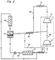
- the systemcomprises a throttle to control refrigerant flow, shown as an expansion valve 11, a first evaporator 13, a two stage compressor 14 having a first and second stage 15 and 17, respectively, a condenser 21, a capillary tube 23, and a second evaporator 25, connected together in that order, in series, in a refrigerant flow relationship by conduit 26.
- a phase separator 27, shown in cross section in Figure 3,comprises a closed receptacle 31 having an inlet 33 at its upper portion for admitting liquid and gaseous phase refrigerant and having two outlets 35 and 37.
- a screen 44is located in the upper portion of the receptacle to remove any solid material carried along with the refrigerant when entering the inlet 33.
- the first outlet 35is located at the bottom of the receptacle 31 and provides liquid refrigerant 39.
- the second outlet 37is provided by a conduit which extends from the interior of the upper portion of the receptacle to the exterior. The conduit is in flow communication with the upper portion and is arranged so that liquid refrigerant entering the upper portion of the receptacle through inlet 33 cannot enter the open end of the conduit.
- Two phase refrigerant from the capillary tubeis connected to the inlet 33 of the phase separator 27. The phase separator provides liquid refrigerant to the expansion valve 11.
- the phase separatoralso provides saturated refrigerant vapor which combines with vapor output by the first compressor 15 and together are connected to the inlet of the second compressor 17.
- the capillary tube 23has a fraction of its length in thermal contact with the conduit which connects the phase separator with the junction of the outlet of the first compressor stage and the second compressor stage suction line. The remaining fraction of the capillary tube is in thermal contact with the first compressor stage suction line. Thermal contact can be achieved by soldering the exterior of the capillary tube and the exterior of the conduit together side by side.
- Figure 2shows the capillary tube wrapped around the conduit 26. This, however, is a schematic representation of a heat transfer relationship.
- the heat transferoccurs in a counterflow arrangement with the capillary tube flow proceeding in a direction opposite to the refrigerant conduit flow to maximize the heat exchange efficiency.
- the first and second compressor stagesare preferably located in a single unit 14 driven by a single motor (not shown).
- the first evaporator 13contains refrigerant at a temperature of approximately -23.3°C (-10°F) for cooling the freezer compartment.
- the second evaporator 25contains the refrigerant at a temperature of approximately -3.9°C (25°F) for cooling the fresh food compartment.
- the expansion valve 11is adjusted to obtain just barely dry gas flow at the exit of evaporator 13, or a capillary tube having the appropriate bore size and length can alternatively be used.
- the gas entering the first compressor stage 15 from evaporator 13is compressed.
- the gas discharged from the first compressor stageis mixed with gas at the saturation temperature from the phase separator 27 and the two gases are further compressed by the second compressor stage 17.
- the high temperature, high pressure discharge gas from the second compressor stageis condensed in condenser 21.
- the capillary tube 23is sized to obtain some subcooling of the liquid exiting the condenser.
- the capillary tubeis a fixed length of a small diameter tube.
- the capillary tubemeters the flow of refrigerant and maintains a pressure difference between the condenser and evaporator.
- the compressor suction line temperatures for the first and second stages in the present embodimentsare approximately -23.3°C (-10°F) and -3.9°C (25°F) without suction line heating from the capillary tube, moisture from the room temperature air, condensing on these lines causes parasitic heat gains to the refrigerant reducing efficiency. The condensing moisture also tends to drip creating a separate problem.
- Suction line heating by means of the capillary tubewarms the suction lines sufficiently to avoid condensation and also cools the refrigerant in the capillary tube flowing to the evaporator. Warming of the refrigerant vapor in the suction lines has an adverse effect on efficiency but when combined with beneficial effect of the cooling of the refrigerant in the capillary tube, overall system efficiency increases.
- the expansion of the liquid refrigerant in the capillary tubecauses part of the liquid to evaporate and cool the remainder to the second evaporator temperature.
- the liquid and gas phase refrigerantenters the phase separator 27. Liquid refrigerant accumulates in the lower portion of the receptacle and gas accumulates in the upper portion.
- the phase separatorsupplies the gas portion to be combined with the gas exiting the first stage compressor 15. The gas from the phase separator it at approximately -3.9°C (25°F) and cools the gas exiting from the first stage compressor, thereby lowering the gas temperature entering the second compressor 17 from what it would have otherwise have been without the intercooling.
- the liquid of the two phase mixture from the second evaporator 25flows from the phase separator 27 through the first throttle 11 causing the refrigerant to a still lower pressure.
- the remaining liquidevaporates in the first evaporator 13 cooling the evaporator to approximately -23.3°C (-10°F).
- a sufficient refrigerant chargeis supplied to the system so that the desired liquid level can be maintained in the phase separator.
- the pressure ratio of the two compressor stagesis determined by the type of refrigerant used and the temperatures at which the evaporators are to operate.
- the pressure at the input to the first compressor 15is determined by the pressure at which the refrigerant exists in two phase equilibrium at -23.3°C (-10°F).
- the pressure at the output of the first compressor stageis determined by the saturation pressure of the refrigerant at-3.9°C (25°F).
- the temperature of the condenser 21has to be greater than that of the ambient temperature in order to function as a heat exchanger under a wide range of operating conditions. If the condenser is to operate at 40.6°C (105°F), for example, then the pressure of the refrigerant at saturation can be determined.
- the volume displacement capability of the compressorsare determined by the amount of cooling capacity the system requires at each of the two temperature levels, which determines the mass flow rate of the refrigerant through the compressor stages.
- the dual evaporator two-stage cyclerequires less mechanical energy compared to a single evaporator single compressor cycle with the same cooling capacity.
- the efficiency advantagescome about due to the fact that the gas leaving the higher temperature evaporator is compressed from an intermediate pressure, rather than from the lower pressure of the gas leaving the lower temperature evaporator.
- Also contributing to improved efficiencyis the cooling of the gas exiting the first compressor by the addition of gas cooled to saturation temperature from the phase separator. The cooling of the gas entering the second compressor reduces the mechanical energy requirement of the second compressor.
- FIG 4.Another embodiment of the present invention is shown in Figure 4.
- the systemcomprises the same components that are used in Figure 2, interconnected in the same way except for a capillary tube 51 which is used in place of the expansion valve 11 in Figure 2.
- the capillary tube 51is connected in a refrigerant flow relationship between the liquid outlet port of the phase separator and the inlet to the first evaporator as in Figure 2 but is also situated in a heat transfer relationship with the refrigerant line exiting the first evaporator 13.
- the capillary tube 51is preferably soldered to the conduit exiting the first evaporator in a counterflow arrangement.
- Capillary tube 23is soldered to the portion of the conduit exiting the first evaporator closer to inlet of the first compressor stage 15 than where the fractional portion of the capillary tube 51 is soldered.
- a fraction of the capillary tube 23is cooled first by contact with the vapor line extending from the phase separator to the input of the second stage compressor. After cooling by contact with this vapor line the first capillary tube 23 is still warmer than the second capillary tube 51 before the second capillary tube contacts the the outlet conduit from the first evaporator. Therefore the second capillary tube 51 contacts a portion of the conduit leading from the first evaporator to the inlet of the first compressor stage which has not been heated by the first capillary tube. If capillary tube 23 were to contact the portion of the conduit closest to the evaporator, the temperature of the conduit would be raised sufficiently to prevent cooling of capillary tube 51 by contact with the conduit.
- Capillary tube 51causes the refrigerant supplied to the first evaporator to be cooler and the refrigerant supplied to the first stage compressor to be warmer than they would be if capillary tube 51 were not in a heat transfer relationship with the outlet of the first evaporator.
- the use of capillary tube 51 in a heat transfer reationshipfurther increases the overall efficiency but not by an amount as great as the improvement introduced by suction line heating provided by capillary tube 23, since the temperature difference between the capillary tube 51 and the first stage compressor suction line is less than that between capillary tube 23 and the suction lines with which it is in contact.
- the compressorscan be of the reciprocating type with hermetically sealed motors or of the rotary type with hermetically sealed motors or of any positive displacement type with hermetically sealed motors.
- the first compressor when refrigerant R-12 is usedcan be very small and operates against a pressure ratio of only 2, which could allow the use of, for example, an inexpensive diaphragm compressor. Improved efficiency can be achieved by operating both compressors from a single motor. Since a larger motor can be more efficient than two smaller motors providing the same total power.
- the compressor adiabatic efficiencywas assumed to be 0.61, motor efficiency 0.8 and additional heating of suction gas due to heat transfer from the compressor shell 6.1°C (43 °F).
- the capillary tube heat transfer to the suction line of the compressorresults in suction gas heating to 36.7°C (98°F).
- the condenser entrance saturation temperatureis assumed to be 54.4°C (130°F), the pressure drop 0.7Kg/cm2 (10 psi), and exit subcooling 150°C (5°F).
- the motor discharge temperatureis calculated to be 220.5°C(429°F), refrigerant flow rate 8.4 Kg/hr (18.6 1bm/hr), compressor power 270 Watts and the coefficient of performance 1.09.
- the first evaporatorwas assumed to have an exit saturation temperature 23.3°C (-10°F), with a pressure drop of 1 psi and an exit superheat of -17.8°C (0°F).
- the second evaporatoris assumed to have an exit temperature of -3.9°C (25°F) and 0 Kg/cm2 (psi) pressure drop.
- the first and second compressorhave an adiabatic efficiency of 0.7 and a motor efficiency of 0.8.
- the first compressorproduces an additional superheating of suction gas due to heat transfer from the compressor shell -15°C (5°F).
- the second compressorhas an additional superheating of suction gas of -12.2°C (10°F).
- the condenserhas an entrance saturation temperature of 54.4°C (130°F), a pressure drop of 0.7 Kg/cm2 (10 psi) and an exit subcooling -15°C (5°F).
- the cooling capacity of 2.931 X 10²W (1000 Btu/hr)is divided equally between the two evaporators.
- the computed results from the above parameters for the cycle in Figure 2are a second compressor discharge gas temperature of 97.8°C (208°F) and a first stage compressor discharge gas temperature of 18.9°C (66°F).
- the compressor flow rates of the first and second compressorsare 3.6 Kg/hr (8.0 1bm/hr) and 11.2 Kg/hr (24.7 1bm/hr), respectively.
- the first and second compressor power consumptionsare 22.2 and 164 watts, respectively.
- the coefficient of performanceis 1.58.
- first and second stage suction line heatingWith first and second stage suction line heating with half the capillary tube length soldered to each of the compressor stages suction lines the first stage suction line temperature is calculated to be 13.9°C (57°F) and the second stage suction line temperature is calculated to be 34.4°C (94°F).
- the coefficient of performanceis calculated to improve by 2.5% compared to the same cycle without suction line heating to a coefficient of performance of 1.62.
- Embodiments of the inventionmay also provide a refrigerator system suitable for use in household refrigerators which reduces the gas temperature at the compressor discharge ports and/or provide a refrigerator system which does not have moisture condensing from the air, on the compressor suction lines.
Landscapes
- Engineering & Computer Science (AREA)
- Physics & Mathematics (AREA)
- Mechanical Engineering (AREA)
- Thermal Sciences (AREA)
- General Engineering & Computer Science (AREA)
- Devices That Are Associated With Refrigeration Equipment (AREA)
Description
- The present invention relates to refrigerators e.g. household refrigerators.
- Currently produced household refrigerators operate on the simple vapor compression cycle as known from AU-B-53080/79. The prior art cycle shown in Figure 1, includes a compressor A, condenser B, expansion valve C, evaporator D, and a two phase refrigerant. In the cycle shown, a capillary tube acts as a throttle. The capillary tube is placed in close proximity with the suction line of the compressor to cool the capillary tube. The subcooling which occurs to the refrigerant in the capillary tube increases the cooling capacity per unit mass flow rate in the system thereby increasing system efficiency which more than compensates for the disadvantage of increasing the temperature of the gas supplied to the compressor. The evaporator in Fig. 1 operates at approximately -23.3°C (-10°F). Refrigerator air is blown across the evaporator and the air flow is controlled so that part of the air flow goes to the freezer compartment and the remainder of the flow goes to the fresh food compartment. The refrigerator cycle, therefore, produces its refrigeration effect at a temperature which is appropriate for the freezer, but lower than it needs to be for the fresh food compartment. Since the mechanical energy required to produce cooling at low temperatures is greater than it is at higher temperatures, the simple vapor compression cycle uses more mechanical energy than one which produces cooling at two temperature levels.
- A well known procedure to reduce mechanical energy use is to operate two independent refrigeration cycles, one to serve the freezer at low temperatures and one to serve the fresh food compartment at an intermediate temperature. Such a system, however, is very costly.
- Another problem which occurs in cooling for freezer operation in the simple vapor compression cycle, is the large temperature difference between the inlet and outlet temperatures of the compressor. The gas exiting the compressor is superheated, which represents a thermodynamic irreversibility which results in a relatively low thermodynamic efficiency. Lowering the amount of superheat will provide for decreased use of mechanical energy and therefore greater efficiency.
- US-A-4435962 shows a two-evaporator arrangement with interposed phase separator and US-A-4 745 777 shows a two-stage compressor with an outlet of a phase separator being connected between both compressor stages.
- According to the present invention, there is provided a refrigeration system using a two phase refrigerant for use in a refrigerator having a freezer compartment and a fresh food compartment, said refrigeration system comprising: a refrigerant flow control means; a first evaporator for providing cooling to the freezer compartment; a two stage compressor; a condenser; a capillary tube; a second evaporator for providing cooling to the fresh food compartment; conduit means for connecting all the above elements together in series in the order listed, in a refrigerant flow relationship; and a phase separator having an inlet and two outlets, the first outlet for providing liquid phase refrigerant, the second outlet for providing gaseous phase refrigerant, said phase separator having its inlet connected to said second evaporator and its first outlet connected to the refrigerant flow control means by said conduit means, the second outlet of said phase separator connected between the first and second stages of said compressor, a first fraction of said capillary tube in a heat transfer relationship with the conduit means connecting said phase separator second outlet between the first and second stages of said compressor, a second fraction of said capillary tube in a heat transfer relationship with the conduit means connecting said first evaporator with the suction side of said first stage compressor.
- The invention, however, both as to organization and method of practice, may be better understood by reference to the following illustrative description taken in conjunction with accopanying figures in which:
- Figure 1 is a schematic representation of a prior art vapor compression system used in a household refrigerator;
- Figure 2 is a schematic representation of one embodiment of a dual evaporator two-stage system in accordance with the present invention;
- Figure 3 is a sectional view of the phase separator of Figure 2; and
- Figure 4 is a schematic representation of another embodiment of a dual evaporator two-stage system in accordance with the present invention.
- Referring now to the drawing and particularly Figure 2 thereof, one embodiment of a dual evaporator two-stage system is shown. The system comprises a throttle to control refrigerant flow, shown as an expansion valve 11, a
first evaporator 13, a twostage compressor 14 having a first andsecond stage condenser 21, acapillary tube 23, and asecond evaporator 25, connected together in that order, in series, in a refrigerant flow relationship byconduit 26. Aphase separator 27, shown in cross section in Figure 3, comprises a closedreceptacle 31 having aninlet 33 at its upper portion for admitting liquid and gaseous phase refrigerant and having twooutlets inlet 33. Thefirst outlet 35 is located at the bottom of thereceptacle 31 and providesliquid refrigerant 39. Thesecond outlet 37 is provided by a conduit which extends from the interior of the upper portion of the receptacle to the exterior. The conduit is in flow communication with the upper portion and is arranged so that liquid refrigerant entering the upper portion of the receptacle throughinlet 33 cannot enter the open end of the conduit. Two phase refrigerant from the capillary tube is connected to theinlet 33 of thephase separator 27. The phase separator provides liquid refrigerant to the expansion valve 11. The phase separator also provides saturated refrigerant vapor which combines with vapor output by thefirst compressor 15 and together are connected to the inlet of thesecond compressor 17. Thecapillary tube 23 has a fraction of its length in thermal contact with the conduit which connects the phase separator with the junction of the outlet of the first compressor stage and the second compressor stage suction line. The remaining fraction of the capillary tube is in thermal contact with the first compressor stage suction line. Thermal contact can be achieved by soldering the exterior of the capillary tube and the exterior of the conduit together side by side. Figure 2 shows the capillary tube wrapped around theconduit 26. This, however, is a schematic representation of a heat transfer relationship. The heat transfer occurs in a counterflow arrangement with the capillary tube flow proceeding in a direction opposite to the refrigerant conduit flow to maximize the heat exchange efficiency. The first and second compressor stages are preferably located in asingle unit 14 driven by a single motor (not shown). - In operation, the
first evaporator 13 contains refrigerant at a temperature of approximately -23.3°C (-10°F) for cooling the freezer compartment. Thesecond evaporator 25 contains the refrigerant at a temperature of approximately -3.9°C (25°F) for cooling the fresh food compartment. - The expansion valve 11 is adjusted to obtain just barely dry gas flow at the exit of
evaporator 13, or a capillary tube having the appropriate bore size and length can alternatively be used. The gas entering thefirst compressor stage 15 fromevaporator 13 is compressed. The gas discharged from the first compressor stage is mixed with gas at the saturation temperature from thephase separator 27 and the two gases are further compressed by thesecond compressor stage 17. The high temperature, high pressure discharge gas from the second compressor stage is condensed incondenser 21. Thecapillary tube 23 is sized to obtain some subcooling of the liquid exiting the condenser. The capillary tube is a fixed length of a small diameter tube. Because of the small diameter a high pressure drop occurs along the capillary tube length reducing the pressure of the liquid refrigerant below its saturation pressure causing it to change to a gas. The capillary tube meters the flow of refrigerant and maintains a pressure difference between the condenser and evaporator. The direct contact between the outside of the warm capillary tube into which the warm condensed liquid from the condenser enters and the outside of the saturated vapor line from the phase separator, causes the cooler vapor line to warm and the capillary tube to cool. Since the compressor suction line temperatures for the first and second stages in the present embodiments are approximately -23.3°C (-10°F) and -3.9°C (25°F) without suction line heating from the capillary tube, moisture from the room temperature air, condensing on these lines causes parasitic heat gains to the refrigerant reducing efficiency. The condensing moisture also tends to drip creating a separate problem. Suction line heating by means of the capillary tube warms the suction lines sufficiently to avoid condensation and also cools the refrigerant in the capillary tube flowing to the evaporator. Warming of the refrigerant vapor in the suction lines has an adverse effect on efficiency but when combined with beneficial effect of the cooling of the refrigerant in the capillary tube, overall system efficiency increases. The expansion of the liquid refrigerant in the capillary tube causes part of the liquid to evaporate and cool the remainder to the second evaporator temperature. The liquid and gas phase refrigerant enters thephase separator 27. Liquid refrigerant accumulates in the lower portion of the receptacle and gas accumulates in the upper portion. The phase separator supplies the gas portion to be combined with the gas exiting thefirst stage compressor 15. The gas from the phase separator it at approximately -3.9°C (25°F) and cools the gas exiting from the first stage compressor, thereby lowering the gas temperature entering thesecond compressor 17 from what it would have otherwise have been without the intercooling. The liquid of the two phase mixture from thesecond evaporator 25 flows from thephase separator 27 through the first throttle 11 causing the refrigerant to a still lower pressure. The remaining liquid evaporates in thefirst evaporator 13 cooling the evaporator to approximately -23.3°C (-10°F). A sufficient refrigerant charge is supplied to the system so that the desired liquid level can be maintained in the phase separator. - The pressure ratio of the two compressor stages is determined by the type of refrigerant used and the temperatures at which the evaporators are to operate. The pressure at the input to the
first compressor 15 is determined by the pressure at which the refrigerant exists in two phase equilibrium at -23.3°C (-10°F). The pressure at the output of the first compressor stage is determined by the saturation pressure of the refrigerant at-3.9°C (25°F). The temperature of thecondenser 21 has to be greater than that of the ambient temperature in order to function as a heat exchanger under a wide range of operating conditions. If the condenser is to operate at 40.6°C (105°F), for example, then the pressure of the refrigerant at saturation can be determined. The volume displacement capability of the compressors are determined by the amount of cooling capacity the system requires at each of the two temperature levels, which determines the mass flow rate of the refrigerant through the compressor stages. - The dual evaporator two-stage cycle requires less mechanical energy compared to a single evaporator single compressor cycle with the same cooling capacity. The efficiency advantages come about due to the fact that the gas leaving the higher temperature evaporator is compressed from an intermediate pressure, rather than from the lower pressure of the gas leaving the lower temperature evaporator. Also contributing to improved efficiency is the cooling of the gas exiting the first compressor by the addition of gas cooled to saturation temperature from the phase separator. The cooling of the gas entering the second compressor reduces the mechanical energy requirement of the second compressor.
- Another embodiment of the present invention is shown in Figure 4. The system comprises the same components that are used in Figure 2, interconnected in the same way except for a
capillary tube 51 which is used in place of the expansion valve 11 in Figure 2. Thecapillary tube 51 is connected in a refrigerant flow relationship between the liquid outlet port of the phase separator and the inlet to the first evaporator as in Figure 2 but is also situated in a heat transfer relationship with the refrigerant line exiting thefirst evaporator 13. Thecapillary tube 51 is preferably soldered to the conduit exiting the first evaporator in a counterflow arrangement.Capillary tube 23 is soldered to the portion of the conduit exiting the first evaporator closer to inlet of thefirst compressor stage 15 than where the fractional portion of thecapillary tube 51 is soldered. - In operation, a fraction of the
capillary tube 23 is cooled first by contact with the vapor line extending from the phase separator to the input of the second stage compressor. After cooling by contact with this vapor line the firstcapillary tube 23 is still warmer than the secondcapillary tube 51 before the second capillary tube contacts the the outlet conduit from the first evaporator. Therefore the secondcapillary tube 51 contacts a portion of the conduit leading from the first evaporator to the inlet of the first compressor stage which has not been heated by the first capillary tube. Ifcapillary tube 23 were to contact the portion of the conduit closest to the evaporator, the temperature of the conduit would be raised sufficiently to prevent cooling ofcapillary tube 51 by contact with the conduit.Capillary tube 51 causes the refrigerant supplied to the first evaporator to be cooler and the refrigerant supplied to the first stage compressor to be warmer than they would be ifcapillary tube 51 were not in a heat transfer relationship with the outlet of the first evaporator. The use ofcapillary tube 51 in a heat transfer reationship further increases the overall efficiency but not by an amount as great as the improvement introduced by suction line heating provided bycapillary tube 23, since the temperature difference between thecapillary tube 51 and the first stage compressor suction line is less than that betweencapillary tube 23 and the suction lines with which it is in contact. - When refrigerant R-12 is used the relative compressor sizes (displacements) in the two stage dual evaporator cycles of both Figures 2 and 4 of the first and second stage compressors are 0.27 and 0.45 compared to a compressor size of 1 for the simple vapor compression cycle, for the same overall refrigeration capacity.
- In the embodiments of Figures 2 and 4 the compressors can be of the reciprocating type with hermetically sealed motors or of the rotary type with hermetically sealed motors or of any positive displacement type with hermetically sealed motors. The first compressor when refrigerant R-12 is used can be very small and operates against a pressure ratio of only 2, which could allow the use of, for example, an inexpensive diaphragm compressor. Improved efficiency can be achieved by operating both compressors from a single motor. Since a larger motor can be more efficient than two smaller motors providing the same total power.
- Performance calculations for the cycles of Figure 1 and Figure 2 follow. All cycles are assumed to use R12 refrigerant and the total cooling capacity of each of the cycles was assumed to be 2.931 X 10²W (1000 Btu/hr.) In addition, all cycles are assumed to use rotary compressors with hermetically sealed motors cooled by refrigerant at the discharge pressure of the compressor. For the prior art cycle of Figure 1 the evaporator exit saturation temperature was assumed to be -23.3°C (-10°F), and have a pressure drop of 0.07Kg/cm² (1 psi) and an exit superheat of -17.8°C (0°F). The compressor adiabatic efficiency was assumed to be 0.61, motor efficiency 0.8 and additional heating of suction gas due to heat transfer from the compressor shell 6.1°C (43 °F). The capillary tube heat transfer to the suction line of the compressor results in suction gas heating to 36.7°C (98°F). The condenser entrance saturation temperature is assumed to be 54.4°C (130°F), the pressure drop 0.7Kg/cm² (10 psi), and exit subcooling 150°C (5°F).
- Based on these parameters, the motor discharge temperature is calculated to be 220.5°C(429°F), refrigerant flow rate 8.4 Kg/hr (18.6 1bm/hr), compressor power 270 Watts and the coefficient of performance 1.09.
- For the cycle of Figure 2 the first evaporator was assumed to have an exit saturation temperature 23.3°C (-10°F), with a pressure drop of 1 psi and an exit superheat of -17.8°C (0°F). The second evaporator is assumed to have an exit temperature of -3.9°C (25°F) and 0 Kg/cm² (psi) pressure drop. The first and second compressor have an adiabatic efficiency of 0.7 and a motor efficiency of 0.8. The first compressor produces an additional superheating of suction gas due to heat transfer from the compressor shell -15°C (5°F). The second compressor has an additional superheating of suction gas of -12.2°C (10°F). The condenser has an entrance saturation temperature of 54.4°C (130°F), a pressure drop of 0.7 Kg/cm² (10 psi) and an exit subcooling -15°C (5°F). The cooling capacity of 2.931 X 10²W (1000 Btu/hr) is divided equally between the two evaporators.
- The computed results from the above parameters for the cycle in Figure 2 are a second compressor discharge gas temperature of 97.8°C (208°F) and a first stage compressor discharge gas temperature of 18.9°C (66°F). The compressor flow rates of the first and second compressors are 3.6 Kg/hr (8.0 1bm/hr) and 11.2 Kg/hr (24.7 1bm/hr), respectively. The first and second compressor power consumptions are 22.2 and 164 watts, respectively. The coefficient of performance is 1.58. With first and second stage suction line heating with half the capillary tube length soldered to each of the compressor stages suction lines the first stage suction line temperature is calculated to be 13.9°C (57°F) and the second stage suction line temperature is calculated to be 34.4°C (94°F). The coefficient of performance is calculated to improve by 2.5% compared to the same cycle without suction line heating to a coefficient of performance of 1.62.
- While the calculations were performed using a refrigerant containing chlorofluorocarbons, other types of refrigerant can be used, with similar advantages compared to presently used cycles.
- The foregoing has described a refrigerator system with dual evaporators suitable for use with household refrigerators that has improved thermodynamic efficiency.
- Embodiments of the invention may also provide a refrigerator system suitable for use in household refrigerators which reduces the gas temperature at the compressor discharge ports and/or provide a refrigerator system which does not have moisture condensing from the air, on the compressor suction lines.
Claims (6)
- A refrigeration system using a two phase refrigerant for use in a refrigerator having a freezer compartment and a fresh food compartment, said refrigeration system comprising:
a refrigerant flow control means (11);
a first evaporator (13) for providing cooling to the freezer compartment;
a two stage compressor (14,15,17);
a condenser (21);
a capillary tube (23);
a second evaporator for providing cooling to the fresh food compartment (25);
conduit means (26) for connecting all the above elements together in series in the order listed, in a refrigerant flow relationship; and
a phase separator (27) having an inlet (33) and two outlets (37,35), the first outlet (35) for providing liquid phase refrigerant, the second outlet (37) for providing gaseous phase refrigerant, said phase separator having its inlet (33) connected to said second (25) evaporator and its first outlet (35) connected to the refrigerant flow control means (11) by said conduit means (26), the second outlet (37) of said phase separator connected between the first (15) and second (17) stages of said compressor, a first fraction of said capillary tube (23) in a heat transfer relationship with the conduit means connecting said phase separator second outlet (37) between the first (15) and second (17) stages of said compressor (14), a second fraction of said capillary tube (23) in a heat transfer relationship with the conduit means connecting said first evaporator (13) with the suction side of said first stage (15) compressor. - The refrigeration system of claim 1 wherein said heat transfer relationship comprises a counterflow heat transfer relationship with the exterior of the capillary tube (23) soldered to the exterior of said conduit means (26).
- The refrigeration system of claim 1 wherein said refrigerant flow control means comprises a further capillary tube (51).
- The refrigeration system of claim 3 wherein the further capillary tube (51) is in a heat transfer relationship with a portion of the conduit means connecting said first evaporator (13) with the suction side of said first stage compressor (15), said portion located between the first evaporator (13) and where said second fraction of said first-mentioned capillary tube (23) is in a heat transfer relationship with the conduit means (26).
- The refrigeration system of claim 4 wherein said heat transfer relationships comprise a counterflow heat transfer relationship with the exterior of the capillary tubes (23,51) soldered to the exterior of said conduit means (26).
- The refrigeration system of claim 1 wherein the flow control means (11) comprises an expansion valve (11).
Applications Claiming Priority (2)
| Application Number | Priority Date | Filing Date | Title |
|---|---|---|---|
| US419982 | 1989-10-11 | ||
| US07/419,982US4918942A (en) | 1989-10-11 | 1989-10-11 | Refrigeration system with dual evaporators and suction line heating |
Publications (3)
| Publication Number | Publication Date |
|---|---|
| EP0424003A2 EP0424003A2 (en) | 1991-04-24 |
| EP0424003A3 EP0424003A3 (en) | 1991-05-08 |
| EP0424003B1true EP0424003B1 (en) | 1993-09-01 |
Family
ID=23664576
Family Applications (1)
| Application Number | Title | Priority Date | Filing Date |
|---|---|---|---|
| EP90311023AExpired - LifetimeEP0424003B1 (en) | 1989-10-11 | 1990-10-09 | Refrigeration system |
Country Status (5)
| Country | Link |
|---|---|
| US (1) | US4918942A (en) |
| EP (1) | EP0424003B1 (en) |
| JP (1) | JP2865844B2 (en) |
| DE (1) | DE69003067T2 (en) |
| ES (1) | ES2045823T3 (en) |
Families Citing this family (65)
| Publication number | Priority date | Publication date | Assignee | Title |
|---|---|---|---|---|
| US5079929A (en)* | 1979-07-31 | 1992-01-14 | Alsenz Richard H | Multi-stage refrigeration apparatus and method |
| US5238557A (en)* | 1990-01-24 | 1993-08-24 | Hewlett Packard Company | Apparatus for controlling the temperature of the mobile phase in a fluid chromatograph |
| US5228308A (en)* | 1990-11-09 | 1993-07-20 | General Electric Company | Refrigeration system and refrigerant flow control apparatus therefor |
| EP0485147B1 (en) | 1990-11-09 | 1996-06-19 | General Electric Company | Refrigeration system |
| US5103650A (en)* | 1991-03-29 | 1992-04-14 | General Electric Company | Refrigeration systems with multiple evaporators |
| US5134859A (en)* | 1991-03-29 | 1992-08-04 | General Electric Company | Excess refrigerant accumulator for multievaporator vapor compression refrigeration cycles |
| US5163304A (en)* | 1991-07-12 | 1992-11-17 | Gary Phillippe | Refrigeration system efficiency enhancer |
| US5174123A (en)* | 1991-08-23 | 1992-12-29 | Thermo King Corporation | Methods and apparatus for operating a refrigeration system |
| US5191776A (en)* | 1991-11-04 | 1993-03-09 | General Electric Company | Household refrigerator with improved circuit |
| US5235820A (en)* | 1991-11-19 | 1993-08-17 | The University Of Maryland | Refrigerator system for two-compartment cooling |
| US5259213A (en)* | 1991-12-19 | 1993-11-09 | Gary Phillippe | Heat pump efficiency enhancer |
| US5156016A (en)* | 1992-02-03 | 1992-10-20 | General Electric Company | Pressure controlled switching valve for refrigeration system |
| US5184473A (en)* | 1992-02-10 | 1993-02-09 | General Electric Company | Pressure controlled switching valve for refrigeration system |
| US5406805A (en)* | 1993-11-12 | 1995-04-18 | University Of Maryland | Tandem refrigeration system |
| WO1996007859A1 (en)* | 1994-09-07 | 1996-03-14 | General Electric Company | Refrigerator multiplex damper system |
| US5600961A (en)* | 1994-09-07 | 1997-02-11 | General Electric Company | Refrigeration system with dual cylinder compressor |
| US5546757A (en)* | 1994-09-07 | 1996-08-20 | General Electric Company | Refrigeration system with electrically controlled expansion valve |
| US5611211A (en)* | 1994-09-07 | 1997-03-18 | General Electric Company | Refirgeration system with electrically controlled refrigerant storage device |
| US5711159A (en)* | 1994-09-07 | 1998-01-27 | General Electric Company | Energy-efficient refrigerator control system |
| US6370908B1 (en) | 1996-11-05 | 2002-04-16 | Tes Technology, Inc. | Dual evaporator refrigeration unit and thermal energy storage unit therefore |
| WO2000000774A1 (en)* | 1998-06-30 | 2000-01-06 | Ebara Corporation | Heat exchanger, heat pump, dehumidifier, and dehumidifying method |
| WO2001022008A1 (en)* | 1999-09-24 | 2001-03-29 | Sanyo Electric Co., Ltd. | Multi-stage compression refrigerating device |
| JP2001091071A (en)* | 1999-09-24 | 2001-04-06 | Sanyo Electric Co Ltd | Multi-stage compression refrigerating machine |
| JP3630632B2 (en) | 2000-12-12 | 2005-03-16 | 株式会社東芝 | refrigerator |
| JP2003207248A (en) | 2002-01-15 | 2003-07-25 | Toshiba Corp | refrigerator |
| TWI301188B (en)* | 2002-08-30 | 2008-09-21 | Sanyo Electric Co | Refrigeant cycling device and compressor using the same |
| JP4118254B2 (en)* | 2004-06-18 | 2008-07-16 | 三洋電機株式会社 | Refrigeration equipment |
| US7137270B2 (en)* | 2004-07-14 | 2006-11-21 | Carrier Corporation | Flash tank for heat pump in heating and cooling modes of operation |
| JP4049769B2 (en)* | 2004-08-12 | 2008-02-20 | 三洋電機株式会社 | Refrigerant cycle equipment |
| JP2006053390A (en) | 2004-08-12 | 2006-02-23 | Fuji Photo Film Co Ltd | Production line of photosensitive film |
| KR100688166B1 (en)* | 2004-12-10 | 2007-03-02 | 엘지전자 주식회사 | Air conditioner |
| CA2592189A1 (en)* | 2004-12-23 | 2006-07-06 | Submachine Corp. | Reaction drive energy transfer device |
| US7631510B2 (en)* | 2005-02-28 | 2009-12-15 | Thermal Analysis Partners, LLC. | Multi-stage refrigeration system including sub-cycle control characteristics |
| US7213405B2 (en)* | 2005-05-10 | 2007-05-08 | Hussmann Corporation | Two-stage linear compressor |
| CN1865812A (en)* | 2005-05-19 | 2006-11-22 | 量子能技术股份有限公司 | Heat pump system and method for heating a fluid |
| JP4101252B2 (en)* | 2005-05-31 | 2008-06-18 | 三洋電機株式会社 | refrigerator |
| KR100857794B1 (en)* | 2006-01-06 | 2008-09-09 | 엘지전자 주식회사 | Air-conditioning system and Controlling Method for the same |
| WO2007078144A2 (en)* | 2006-01-06 | 2007-07-12 | Lg Electronics Inc. | Air-conditioning system and controlling method thereof |
| US9857103B2 (en)* | 2013-11-04 | 2018-01-02 | Lg Electronics Inc. | Refrigerator having a condensation loop between a receiver and an evaporator |
| CN101568776B (en)* | 2006-10-27 | 2011-03-09 | 开利公司 | Economized refrigeration cycle with expander |
| CN101617182B (en)* | 2007-02-26 | 2012-01-04 | 开利公司 | Energy-efficient refrigerant systems using expanders with intermediate pressure ports |
| US8561425B2 (en)* | 2007-04-24 | 2013-10-22 | Carrier Corporation | Refrigerant vapor compression system with dual economizer circuits |
| US20100147006A1 (en)* | 2007-06-04 | 2010-06-17 | Taras Michael F | Refrigerant system with cascaded circuits and performance enhancement features |
| KR101380036B1 (en)* | 2007-10-25 | 2014-04-01 | 엘지전자 주식회사 | Air conditioner |
| FR2924488A1 (en)* | 2007-11-29 | 2009-06-05 | Eurocave Sa Sa | POSITIVE COLD COOLING UNIT AND DEVICES USING SUCH A UNIT |
| US8794026B2 (en) | 2008-04-18 | 2014-08-05 | Whirlpool Corporation | Secondary cooling apparatus and method for a refrigerator |
| JP4642100B2 (en)* | 2008-09-01 | 2011-03-02 | 三菱電機株式会社 | Heat pump equipment |
| US20110030404A1 (en)* | 2009-08-04 | 2011-02-10 | Sol Xorce Llc | Heat pump with intgeral solar collector |
| JP5705455B2 (en)* | 2010-04-28 | 2015-04-22 | 三菱重工業株式会社 | Heat pump water heater using CO2 refrigerant |
| KR102034582B1 (en) | 2012-07-24 | 2019-11-08 | 엘지전자 주식회사 | Refrigerating cycle and Refrigerator having the same |
| US9234685B2 (en) | 2012-08-01 | 2016-01-12 | Thermo King Corporation | Methods and systems to increase evaporator capacity |
| BR112015014432A2 (en) | 2012-12-18 | 2017-07-11 | Emerson Climate Technologies | reciprocating compressor with steam injection system |
| US20150075212A1 (en)* | 2013-09-16 | 2015-03-19 | The Coca-Cola Company | Carbon Dioxide Refrigeration System with a Multi-Way Valve |
| DE102013218565A1 (en)* | 2013-09-17 | 2015-03-19 | Siemens Aktiengesellschaft | Method for carrying out a thermodynamic process |
| ES2828180T3 (en) | 2013-11-04 | 2021-05-25 | Lg Electronics Inc | Fridge |
| EP3073210A1 (en)* | 2015-03-27 | 2016-09-28 | Whirlpool Corporation | Refrigerator with enhanced efficiency |
| DE102015215491A1 (en)* | 2015-08-13 | 2017-02-16 | BSH Hausgeräte GmbH | Single-circuit refrigerating appliance |
| DE102016202564A1 (en)* | 2016-02-19 | 2017-08-24 | BSH Hausgeräte GmbH | Refrigerating appliance with several storage chambers |
| DE102016202565A1 (en)* | 2016-02-19 | 2017-08-24 | BSH Hausgeräte GmbH | Refrigerating appliance with several storage chambers |
| DE102017204222A1 (en)* | 2017-03-14 | 2018-09-20 | Siemens Aktiengesellschaft | Heat pump and method for operating a heat pump |
| WO2019230463A1 (en)* | 2018-05-28 | 2019-12-05 | キヤノンセミコンダクターエクィップメント株式会社 | Cooling device, exposure device equipped with cooling device, and industrial machine equipped with cooling device |
| CN111435043A (en)* | 2019-01-11 | 2020-07-21 | 青岛海尔智能技术研发有限公司 | Compression type refrigerating system and refrigerating and freezing device |
| CN111256381B (en)* | 2020-01-19 | 2021-09-21 | 珠海格力电器股份有限公司 | Compressor anti-surge air supply system, control method and air conditioning equipment |
| CN111609583B (en)* | 2020-04-24 | 2021-06-04 | 珠海格力电器股份有限公司 | Double-temperature air conditioning system, control method and air conditioner |
| US12078397B2 (en)* | 2020-12-04 | 2024-09-03 | Honeywell International Inc. | Surge control subcooling circuit |
Family Cites Families (15)
| Publication number | Priority date | Publication date | Assignee | Title |
|---|---|---|---|---|
| FR431893A (en)* | 1911-07-04 | 1911-11-22 | Linde Eismasch Ag | Process for regulating refrigeration machines with three or more evaporators, for low temperatures |
| US2500688A (en)* | 1948-08-24 | 1950-03-14 | Edward P Kellie | Refrigerating apparatus |
| US2667756A (en)* | 1952-01-10 | 1954-02-02 | Gen Electric | Two-temperature refrigerating system |
| US2887857A (en)* | 1955-06-28 | 1959-05-26 | Hugh J Scullen | Jet pumps in refrigeration system |
| US3360958A (en)* | 1966-01-21 | 1968-01-02 | Trane Co | Multiple compressor lubrication apparatus |
| US3848422A (en)* | 1972-04-27 | 1974-11-19 | Svenska Rotor Maskiner Ab | Refrigeration plants |
| DE2239297A1 (en)* | 1972-08-10 | 1974-02-21 | Bosch Gmbh Robert | REFRIGERATION SYSTEM, IN PARTICULAR FOR USE IN A MOTOR VEHICLE |
| US3952533A (en)* | 1974-09-03 | 1976-04-27 | Kysor Industrial Corporation | Multiple valve refrigeration system |
| AU528383B2 (en)* | 1978-12-01 | 1983-04-28 | Email Limited | Noise suppression in refrigerators |
| JPS5710063A (en)* | 1980-06-20 | 1982-01-19 | Hitachi Ltd | Refrigerating plant |
| US4439998A (en)* | 1980-09-04 | 1984-04-03 | General Electric Company | Apparatus and method of controlling air temperature of a two-evaporator refrigeration system |
| FR2495293A1 (en)* | 1980-12-01 | 1982-06-04 | Inst Francais Du Petrole | IMPROVEMENT TO THE COLD-PRODUCTION PROCESS USING A DEMIXING CYCLE |
| US4393661A (en)* | 1981-12-10 | 1983-07-19 | General Electric Company | Means and method for regulating flowrate in a vapor compression cycle device |
| SU1134858A1 (en)* | 1983-01-24 | 1985-01-15 | Ленинградский Ордена Ленина Политехнический Институт Им.М.И.Калинина | Refrigerating plant |
| JPS62233645A (en)* | 1986-03-31 | 1987-10-14 | 三菱電機株式会社 | refrigeration cycle |
- 1989
- 1989-10-11USUS07/419,982patent/US4918942A/ennot_activeExpired - Fee Related
- 1990
- 1990-10-04JPJP2265316Apatent/JP2865844B2/ennot_activeExpired - Lifetime
- 1990-10-09ESES90311023Tpatent/ES2045823T3/ennot_activeExpired - Lifetime
- 1990-10-09EPEP90311023Apatent/EP0424003B1/ennot_activeExpired - Lifetime
- 1990-10-09DEDE90311023Tpatent/DE69003067T2/ennot_activeExpired - Fee Related
Also Published As
| Publication number | Publication date |
|---|---|
| ES2045823T3 (en) | 1994-01-16 |
| DE69003067T2 (en) | 1994-04-21 |
| US4918942A (en) | 1990-04-24 |
| JP2865844B2 (en) | 1999-03-08 |
| JPH03164664A (en) | 1991-07-16 |
| DE69003067D1 (en) | 1993-10-07 |
| EP0424003A2 (en) | 1991-04-24 |
| EP0424003A3 (en) | 1991-05-08 |
Similar Documents
| Publication | Publication Date | Title |
|---|---|---|
| EP0424003B1 (en) | Refrigeration system | |
| US4910972A (en) | Refrigerator system with dual evaporators for household refrigerators | |
| US5103650A (en) | Refrigeration systems with multiple evaporators | |
| US6351950B1 (en) | Refrigeration system with variable sub-cooling | |
| US5134859A (en) | Excess refrigerant accumulator for multievaporator vapor compression refrigeration cycles | |
| US5765391A (en) | Refrigerant circulation apparatus utilizing two evaporators operating at different evaporating temperatures | |
| US5191776A (en) | Household refrigerator with improved circuit | |
| JP4982713B2 (en) | Energy efficiency improvement device for refrigeration cycle | |
| JP2001147050A (en) | Refrigerating system for refrigerator equipped with two evaporators | |
| EP0541324A1 (en) | Refrigeration systems | |
| JP3345451B2 (en) | Refrigerant flow switching device and refrigerator | |
| US4528823A (en) | Heat pump apparatus | |
| US4862707A (en) | Two compartment refrigerator | |
| US6857287B1 (en) | Refrigeration cycle | |
| JP3345450B2 (en) | Refrigerant flow switching device and refrigerator | |
| EP0624763A1 (en) | Free-draining evaporator for refrigeration system | |
| EP3862657A1 (en) | Refrigeration system with multiple heat absorbing heat exchangers | |
| EP0374688B1 (en) | Refrigerator system with dual evaporators for household refrigerators | |
| KR200300275Y1 (en) | refrigeration system | |
| KR100550581B1 (en) | Refrigerator with a deep freezer | |
| KR100442380B1 (en) | Refrigerator | |
| CN218096773U (en) | Refrigerator with multiple temperature zones | |
| SU945606A1 (en) | Method and apparatus for producing refrigeration | |
| KR0176887B1 (en) | Evaporator of refrigeration cycle | |
| JP2004138305A (en) | Liquid receiver |
Legal Events
| Date | Code | Title | Description |
|---|---|---|---|
| PUAI | Public reference made under article 153(3) epc to a published international application that has entered the european phase | Free format text:ORIGINAL CODE: 0009012 | |
| PUAL | Search report despatched | Free format text:ORIGINAL CODE: 0009013 | |
| AK | Designated contracting states | Kind code of ref document:A2 Designated state(s):DE ES FR GB IT SE | |
| AK | Designated contracting states | Kind code of ref document:A3 Designated state(s):DE ES FR GB IT SE | |
| 17P | Request for examination filed | Effective date:19911021 | |
| 17Q | First examination report despatched | Effective date:19920409 | |
| GRAA | (expected) grant | Free format text:ORIGINAL CODE: 0009210 | |
| AK | Designated contracting states | Kind code of ref document:B1 Designated state(s):DE ES FR GB IT SE | |
| REF | Corresponds to: | Ref document number:69003067 Country of ref document:DE Date of ref document:19931007 | |
| ET | Fr: translation filed | ||
| ITF | It: translation for a ep patent filed | ||
| REG | Reference to a national code | Ref country code:ES Ref legal event code:FG2A Ref document number:2045823 Country of ref document:ES Kind code of ref document:T3 | |
| PLBE | No opposition filed within time limit | Free format text:ORIGINAL CODE: 0009261 | |
| STAA | Information on the status of an ep patent application or granted ep patent | Free format text:STATUS: NO OPPOSITION FILED WITHIN TIME LIMIT | |
| 26N | No opposition filed | ||
| EAL | Se: european patent in force in sweden | Ref document number:90311023.7 | |
| REG | Reference to a national code | Ref country code:GB Ref legal event code:IF02 | |
| PGFP | Annual fee paid to national office [announced via postgrant information from national office to epo] | Ref country code:FR Payment date:20020918 Year of fee payment:13 | |
| PGFP | Annual fee paid to national office [announced via postgrant information from national office to epo] | Ref country code:SE Payment date:20020919 Year of fee payment:13 | |
| PGFP | Annual fee paid to national office [announced via postgrant information from national office to epo] | Ref country code:GB Payment date:20021002 Year of fee payment:13 | |
| PGFP | Annual fee paid to national office [announced via postgrant information from national office to epo] | Ref country code:DE Payment date:20021031 Year of fee payment:13 | |
| PGFP | Annual fee paid to national office [announced via postgrant information from national office to epo] | Ref country code:ES Payment date:20021106 Year of fee payment:13 | |
| PG25 | Lapsed in a contracting state [announced via postgrant information from national office to epo] | Ref country code:GB Free format text:LAPSE BECAUSE OF NON-PAYMENT OF DUE FEES Effective date:20031009 | |
| PG25 | Lapsed in a contracting state [announced via postgrant information from national office to epo] | Ref country code:SE Free format text:LAPSE BECAUSE OF NON-PAYMENT OF DUE FEES Effective date:20031010 Ref country code:ES Free format text:LAPSE BECAUSE OF NON-PAYMENT OF DUE FEES Effective date:20031010 | |
| PG25 | Lapsed in a contracting state [announced via postgrant information from national office to epo] | Ref country code:DE Free format text:LAPSE BECAUSE OF NON-PAYMENT OF DUE FEES Effective date:20040501 | |
| EUG | Se: european patent has lapsed | ||
| GBPC | Gb: european patent ceased through non-payment of renewal fee | Effective date:20031009 | |
| PG25 | Lapsed in a contracting state [announced via postgrant information from national office to epo] | Ref country code:FR Free format text:LAPSE BECAUSE OF NON-PAYMENT OF DUE FEES Effective date:20040630 | |
| REG | Reference to a national code | Ref country code:FR Ref legal event code:ST | |
| REG | Reference to a national code | Ref country code:ES Ref legal event code:FD2A Effective date:20031010 | |
| PG25 | Lapsed in a contracting state [announced via postgrant information from national office to epo] | Ref country code:IT Free format text:LAPSE BECAUSE OF NON-PAYMENT OF DUE FEES;WARNING: LAPSES OF ITALIAN PATENTS WITH EFFECTIVE DATE BEFORE 2007 MAY HAVE OCCURRED AT ANY TIME BEFORE 2007. THE CORRECT EFFECTIVE DATE MAY BE DIFFERENT FROM THE ONE RECORDED. Effective date:20051009 |