EP0423574A1 - Mixing and proportioning device for reactive plastic components - Google Patents
Mixing and proportioning device for reactive plastic componentsDownload PDFInfo
- Publication number
- EP0423574A1 EP0423574A1EP90119215AEP90119215AEP0423574A1EP 0423574 A1EP0423574 A1EP 0423574A1EP 90119215 AEP90119215 AEP 90119215AEP 90119215 AEP90119215 AEP 90119215AEP 0423574 A1EP0423574 A1EP 0423574A1
- Authority
- EP
- European Patent Office
- Prior art keywords
- metering
- mixing
- component
- mixing head
- piston
- Prior art date
- Legal status (The legal status is an assumption and is not a legal conclusion. Google has not performed a legal analysis and makes no representation as to the accuracy of the status listed.)
- Withdrawn
Links
- 230000001105regulatory effectEffects0.000claimsdescription2
- 230000001276controlling effectEffects0.000claims1
- 230000002441reversible effectEffects0.000claims1
- 238000006073displacement reactionMethods0.000description2
- 238000005259measurementMethods0.000description2
- 230000029058respiratory gaseous exchangeEffects0.000description2
- 230000002411adverseEffects0.000description1
- 238000011161developmentMethods0.000description1
- 230000018109developmental processEffects0.000description1
- 230000000694effectsEffects0.000description1
- 238000002347injectionMethods0.000description1
- 239000007924injectionSubstances0.000description1
- 239000012948isocyanateSubstances0.000description1
- 150000002513isocyanatesChemical class0.000description1
- 210000000056organAnatomy0.000description1
- 229920005862polyolPolymers0.000description1
- 150000003077polyolsChemical class0.000description1
- 238000004904shorteningMethods0.000description1
Images

Classifications
- B—PERFORMING OPERATIONS; TRANSPORTING
- B29—WORKING OF PLASTICS; WORKING OF SUBSTANCES IN A PLASTIC STATE IN GENERAL
- B29B—PREPARATION OR PRETREATMENT OF THE MATERIAL TO BE SHAPED; MAKING GRANULES OR PREFORMS; RECOVERY OF PLASTICS OR OTHER CONSTITUENTS OF WASTE MATERIAL CONTAINING PLASTICS
- B29B7/00—Mixing; Kneading
- B29B7/74—Mixing; Kneading using other mixers or combinations of mixers, e.g. of dissimilar mixers ; Plant
- B29B7/76—Mixers with stream-impingement mixing head
- B29B7/7663—Mixers with stream-impingement mixing head the mixing head having an outlet tube with a reciprocating plunger, e.g. with the jets impinging in the tube
- B29B7/7684—Parts; Accessories
- B29B7/7689—Plunger constructions
- B29B7/7694—Plunger constructions comprising recirculation channels; ducts formed in the plunger
Definitions
- the inventionrelates to a device for metering and mixing at least two reactive plastic components according to the preamble of claim 1.
- a device of this typeis known from DE-0S 32 40 296, in which the individual plastic components are sucked out of the storage tanks in separate metering devices and metered through lines to the mixing head.
- the line spacing between the dosing device and the mixing head, the breathing of the lines consisting of flexible hoses and pipes, and the compressibility of the mediumall have an adverse effect on fast and accurate control constants of the individual components and the resulting deviations in the mixing ratio of the individual components out.
- the inventionis therefore based on the object of improving a device of the type mentioned in such a way that disruptive factors for the control accuracy of the components are eliminated.
- control elements for the hydraulics for driving the metering pistons of the metering deviceare arranged directly on the metering cylinders.
- the control elementseach include a closed control circuit with displacement measurement of the metering piston, with an assigned computer and the executing element of the servo valve, which, due to its direct arrangement on the cylinder unit, contributes to a delay-free hydraulic actuation of the metering piston and thus also to the precise observance of the control constants.
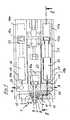
- a mixing head 1 and 2show a mixing head 1, consisting of a housing block 2 with a cylindrical mixing chamber 3, into which a component supply line 4 for component A (eg polyol) and a component supply line 5 for component B (eg isocyanate) open.
- the injection openings 6 and 7 of these component supply lines 4 and 5are opened and closed by a control piston 8 which is reversibly guided in the mixing chamber 3.
- the control piston 8is in the closed position in which the end face 9 is flush with the outlet opening of the mixing chamber 3. In this position, the control piston 8 is also in the recirculation position, in which the component supply lines 4 and 5 are connected via recirculation grooves 10 and 11 formed in the control piston 8 to component recirculation lines 12 and 13, which lead to the respective component tanks (not shown).
- the metering pistons 15, 16consist of plungers with which the components are sucked in from the tank supply lines 19 and 20 via component suction channels 19a, 20a located in the bottom of the metering cylinders 17, 18 and metered via the component discharge channels 4a, 5a and the component supply lines 4 and 5 into the mixing chamber 3 are funded.
- the component supply lines 4 and 5are thus extremely short, so that interference from breathing the line and the compressibility of the components are largely excluded.
- a further shortening of the component supply linescan be achieved by flange-mounting the metering pistons and the metering cylinders directly on the housing block of the mixing head (not shown).
- the tank feed linesexpediently open into the bottoms of the metering cylinders.
- the metering pistons 15, 16are actuated by hydraulic pistons 15a, 16a, which are guided in hydraulic cylinders 17a, 18a and are actuated by regulating members 21 arranged directly on the hydraulic cylinders 17a, 18a, the closed control loop via the displacement measurement of the metering piston 15, 16 an assigned computer and
- the executing organ of the servo valve(not shown) takes place, which ensures a delay-free response of the hydraulics for the metering pistons 15 and 16 because of its direct arrangement on the hydraulic cylinders 17a, 18a.
- the unit 8a, the distributor block 14, the metering pistons 15, 16, the metering cylinders 17, 18 and the associated hydraulic pistons 15a, 16a and hydraulic cylinders 17a, 18ais attached to a travel carriage 22, with which the module by means of an adjusting cylinder 23 on a base frame 24 is displaceable, so that the mixing head 1 can be positioned in an advanced and a retracted position.
- This concept of the assembly of the mixing head and metering device which can be displaced with the traversing carriage 22is particularly advantageous in the case of mold carrier systems in which the assembly with the mixing head is docked to a tool in the feed cycle and after the tool has been filled and the curing time has begun in a retraction cycle can be undocked again.
Landscapes
- Engineering & Computer Science (AREA)
- Mechanical Engineering (AREA)
- Processing And Handling Of Plastics And Other Materials For Molding In General (AREA)
Abstract
Description
Translated fromGermanDie Erfindung bezieht sich auf eine Vorrichtung zum Dosieren und Mischen von wenigstens zwei reaktiven Kunststoffkomponenten gemäß Oberbegriff des Patentanspruchs 1.The invention relates to a device for metering and mixing at least two reactive plastic components according to the preamble of claim 1.
Eine Vorrichtung dieser Art ist aus der DE-0S 32 40 296 bekannt, bei der die einzelnen Kunststoffkomponenten in gesonderten Dosiervorrichtungen aus den Vorratstanks angesaugt und dosiert über Leitungen dem Mischkopf zugeführt werden. Der Leitungsabstand zwischen der Dosiervorrichtung und dem Mischkopf, das Atmen der aus flexiblen Schläuchen und Rohren bestehenden Leitungen sowie die Kompressibilität des Mediums wirken sich dabei in Bezug auf schnelle und genaue Regelkonstanten der einzelnen Komponenten und die sich daraus ergebenden Abweichungen im Mischungsverhältnis der einzelnen Komponenten zueinander nachteilig aus.A device of this type is known from DE-0S 32 40 296, in which the individual plastic components are sucked out of the storage tanks in separate metering devices and metered through lines to the mixing head. The line spacing between the dosing device and the mixing head, the breathing of the lines consisting of flexible hoses and pipes, and the compressibility of the medium all have an adverse effect on fast and accurate control constants of the individual components and the resulting deviations in the mixing ratio of the individual components out.
Der Erfindung liegt daher die Aufgabe zugrunde, eine Vorrichtung der genannten Art so zu verbessern, daß störende Faktoren für die Regelgenauigkeit der Komponenten eliminiert werden.The invention is therefore based on the object of improving a device of the type mentioned in such a way that disruptive factors for the control accuracy of the components are eliminated.
Die Aufgabe wird erfindungsgemäß durch die kennzeichnenden Merkmale des Patentanspruchs 1 gelöst.The object is achieved by the characterizing features of claim 1.
In einer vorteilhaften Ausführungsform sind die Regelorgane Für die Hydraulik zum Antreiben der Dosierkolben der Dosiervorrichtung direkt an den Dosierzylindern angeordnet. Die Regelorgane umfassen dabei jeweils einen geschlossenen Regelkreis mit Wegmessung des Dosierkolbens, mit zugeordnetem Rechner und dem ausführenden Organ des Servoventils, welches aufgrund seiner direkten Anordnung an der Zylindereinheit eine verzögerungsfreie hydraulische Betätigung des Dosierkolbens und damit auch zur präzisen Einhaltung der Regel konstanten beiträgt.In an advantageous embodiment, the control elements for the hydraulics for driving the metering pistons of the metering device are arranged directly on the metering cylinders. The control elements each include a closed control circuit with displacement measurement of the metering piston, with an assigned computer and the executing element of the servo valve, which, due to its direct arrangement on the cylinder unit, contributes to a delay-free hydraulic actuation of the metering piston and thus also to the precise observance of the control constants.
Weitere vorteilhafte Weiterbildungen und Ausgestaltungen der erfindungsgemäßen Misch- und Dosiervorrichtung ergeben sich aus den Unteransprü- chen.Further advantageous developments and refinements of the mixing and metering device according to the invention result from the subclaims.
Die Erfindung wird nachstehend anhand der Zeichnung näher erläutert.The invention is explained below with reference to the drawing.
Es zeigen:
- Fig. 1 die Draufsicht auf eine Misch-und Dosiervorrichtung in teilweise geschnittener Darstellung gemäß der Schnittlinie I-I in Fig. 2,
- Fig. 2 die Seitenansicht der Vorrichtung nach Fig. 1 in teilweise geschnittener Darstellung gemäß der Schnittlinie II-II in Fig 1.
- 1 is a top view of a mixing and dosing device in a partially sectioned view according to section line II in FIG. 2,
- FIG. 2 shows the side view of the device according to FIG. 1 in a partially sectioned illustration according to section line II-II in FIG. 1.
Die Fig. 1 und 2 zeigen einen Mischkopf 1, bestehend aus einem Gehäuseblock 2 mit zylindrischer Mischkammer 3, in die eine Komponentenzulaufleitung 4 für die Komponente A (z.B. Polyol) und eine Komponentenzulaufleitung 5 für die Komponente B (z.B. Isocyanat) einmünden. Die Injektionsöffnungen 6 und 7 dieser Komponentenzulaufleitungen 4 und 5 werden von einem Steuerkolben 8 auf- und zugesteuert, der in der Mischkammer 3 reversierbar geführt ist. Der Steuerkolben 8 befindet sch in der Schließstellung in der dessen Stirnfläche 9 mit der Auslaßöffnung der Mischkammer 3 bündig abschließt. In dieser Stellung befindet sich der Steuerkolben 8 auch in der Rezirkulationsstellung, in der die Komponentenzulaufleitungen 4 und 5 über im Steuerkolben 8 ausgebildete Rezirkulationsnuten 10 und 11 mit Komponentenrezirkulationsleitungen 12 und 13 verbunden sind, die zu den jeweiligen Komponententanks (nicht dargestellt) führen.1 and 2 show a mixing head 1, consisting of a
Am Gehäuseblock 2 sind ferner die hydraulische Kolben-Zylindereinheit 8a für den Steuerkolben 8 und ein Verteilerblock 14 angeordnet, an dem wiederum zwei, jeweils aus einem Dosierkolben 15,16 und einem Dosierzylinder 17,18 bestehende Dosiervorrichtungen für die Komponenten A und B befestigt sind. Die Dosierkolben 15,16 bestehen aus Plungerkolben, mit denen die Komponenten über im Boden der Dosierzylinder 17,18 befindliche Komponentenansaugkanäle 19a,20a aus den Tankzulaufleitungen 19 und 20 angesaugt und dosiert über die Komponentenausstoßkanäle 4a,5a und die Komponentenzulaufleitungen 4 und 5 in die Mischkammer 3 gefördert werden.Also arranged on the
Die Komponentenzulaufleitungen 4 und 5 sind somit äußerst kurz, so daß Störeinflüsse durch Atmen der Leitungsführung und durch die Kompressibilität der Komponenten weitestgehend ausgeschlossen sind. Eine weitere Verkürzung der Komponentenzulaufleitungen kann noch dadurch erreicht werden, daß die Dosierkolben und die Dosierzylinder direkt am Gehäuseblock des Mischkopfes angeflanscht werden (nicht dargestellt). Bei dieser Ausführungsform münden zweckmäßigerweise die Tankzulaufleitungen jeweils in die Böden der Dosierzylinder.The
Die Dosierkolben 15,16 werden von in Hydraulikzylindern 17a,18a geführten Hydraulikkolben 15a,16a betätigt, die von unmittelbar auf den Hydraulikzylindern 17a,18a angeordneten Regelorganen 21 angesteuert werden, wobei der geschlossene Regelkreis über die Wegmessung des Dosierkolbens 15,16 einen zugeordneten Rechner und das ausführende Organ des Servoventils (nicht dargestellt) erfolgt, das wegen seiner unmittelbaren Anordnung am Hydraulikzylinder 17a,18a ein verzögerungsfreies Ansprechen der Hydraulik für die Dosierkolben 15 und 16 sicherstellt.The
Die im wesentlichen aus dem Mischkopf 1, der hydraulischen Kolben-Zylin dereinheit 8a, dem Verteilerblock 14, den Dosierkolben 15,16, den Dosierzylindern 17,18 sowie den zugehörigen Hydraulikkolben 15a,16a und Hydraulikzylindern 17a,18a bestehende Baueinheit ist auf einem Verfahrschlitten 22 befestigt, mit dem die Baueinheit mittels eines Verstellzylinders 23 auf einem Grundgestell 24 verschiebbar ist, so daß der Mischkopf 1 in eine vorgeschobene und in eine zurückgezogene Stellung positioniert werden kann.The essentially from the mixing head 1, the hydraulic piston cylinder The
Diese Konzeption der mit dem Verfahrschlitten 22 verschiebbaren Baueinheit von Mischkopf und Dosiervorrichtung ist insbesondere bei Formträgeranlagen vorteilhaft, bei denen die Baueinheit mit dem Mischkopf im Vorschub-Zyklus jeweils an ein Werkzeug angedockt und nach dem Füllen des Werkzeugs und Beginn der Aushärtezeit in einem Rückzug-Zyklus wieder abgedockt werden kann.This concept of the assembly of the mixing head and metering device which can be displaced with the traversing
Nach der Rückzugbewegung der Baueinheit ist genügend Freiraum vorhanden, wenn die Werkzeuge oder der Formträger geschwenkt werden müssen.After the retraction movement of the assembly there is enough free space if the tools or the mold carrier have to be swiveled.
Die bisher für diesen Fall gegebene Notwendigkeit, den Mischkopf mit flexiblen Schläuchen auszurüsten, enfällt damit.This eliminates the need to equip the mixing head with flexible hoses.
Claims (9)
Translated fromGermanApplications Claiming Priority (2)
| Application Number | Priority Date | Filing Date | Title |
|---|---|---|---|
| DE3934863ADE3934863A1 (en) | 1989-10-19 | 1989-10-19 | MIXING AND DOSING DEVICE FOR REACTIVE PLASTIC COMPONENTS |
| DE3934863 | 1989-10-19 |
Publications (1)
| Publication Number | Publication Date |
|---|---|
| EP0423574A1true EP0423574A1 (en) | 1991-04-24 |
Family
ID=6391778
Family Applications (1)
| Application Number | Title | Priority Date | Filing Date |
|---|---|---|---|
| EP90119215AWithdrawnEP0423574A1 (en) | 1989-10-19 | 1990-10-06 | Mixing and proportioning device for reactive plastic components |
Country Status (3)
| Country | Link |
|---|---|
| EP (1) | EP0423574A1 (en) |
| JP (1) | JPH03140210A (en) |
| DE (1) | DE3934863A1 (en) |
Cited By (1)
| Publication number | Priority date | Publication date | Assignee | Title |
|---|---|---|---|---|
| ITMI20131319A1 (en)* | 2013-08-02 | 2015-02-03 | Afros Spa | DEVICE-INJECTOR AND MECHANISM FOR MIXING POLYMERIC COMPONENTS |
Citations (5)
| Publication number | Priority date | Publication date | Assignee | Title |
|---|---|---|---|---|
| US3117696A (en)* | 1961-07-12 | 1964-01-14 | Cyril J Herman | Gun for two component adhesives |
| US3843023A (en)* | 1973-09-17 | 1974-10-22 | D Vroom | Mixing and dispensing apparatus having nozzel cleaner |
| FR2301292A1 (en)* | 1975-02-22 | 1976-09-17 | Bayer Ag | DEVICE FOR DOSING AND MIXING FLUID CONSTITUENTS COMING INTO REACTION OF A MOLDING MATERIAL |
| GB1530339A (en)* | 1977-11-04 | 1978-10-25 | Viking Eng Co Ltd | Mixing head for foam plastics material |
| EP0003563A1 (en)* | 1978-02-13 | 1979-08-22 | Bayer Ag | Device for dosing at least two fluidisable reaction components in a mixing room |
Family Cites Families (3)
| Publication number | Priority date | Publication date | Assignee | Title |
|---|---|---|---|---|
| DE2945283A1 (en)* | 1979-11-09 | 1981-05-21 | Siemens AG, 1000 Berlin und 8000 München | DEVICE FOR CONVEYING AND DOSING LIQUID MIDIEN |
| DE3412222A1 (en)* | 1984-04-02 | 1985-10-10 | Hilti Ag, Schaan | Metering device for plastic materials |
| DE3630992C2 (en)* | 1986-09-11 | 1995-01-26 | Siemens Ag | Device for dosing and mixing substances |
- 1989
- 1989-10-19DEDE3934863Apatent/DE3934863A1/ennot_activeWithdrawn
- 1990
- 1990-10-06EPEP90119215Apatent/EP0423574A1/ennot_activeWithdrawn
- 1990-10-18JPJP2277947Apatent/JPH03140210A/enactivePending
Patent Citations (5)
| Publication number | Priority date | Publication date | Assignee | Title |
|---|---|---|---|---|
| US3117696A (en)* | 1961-07-12 | 1964-01-14 | Cyril J Herman | Gun for two component adhesives |
| US3843023A (en)* | 1973-09-17 | 1974-10-22 | D Vroom | Mixing and dispensing apparatus having nozzel cleaner |
| FR2301292A1 (en)* | 1975-02-22 | 1976-09-17 | Bayer Ag | DEVICE FOR DOSING AND MIXING FLUID CONSTITUENTS COMING INTO REACTION OF A MOLDING MATERIAL |
| GB1530339A (en)* | 1977-11-04 | 1978-10-25 | Viking Eng Co Ltd | Mixing head for foam plastics material |
| EP0003563A1 (en)* | 1978-02-13 | 1979-08-22 | Bayer Ag | Device for dosing at least two fluidisable reaction components in a mixing room |
Cited By (2)
| Publication number | Priority date | Publication date | Assignee | Title |
|---|---|---|---|---|
| ITMI20131319A1 (en)* | 2013-08-02 | 2015-02-03 | Afros Spa | DEVICE-INJECTOR AND MECHANISM FOR MIXING POLYMERIC COMPONENTS |
| WO2015015002A1 (en)* | 2013-08-02 | 2015-02-05 | Afros S.P.A. | Injecting device and apparatus for mixing polymer components |
Also Published As
| Publication number | Publication date |
|---|---|
| JPH03140210A (en) | 1991-06-14 |
| DE3934863A1 (en) | 1991-04-25 |
Similar Documents
| Publication | Publication Date | Title |
|---|---|---|
| DE2555156C3 (en) | High pressure mixing head | |
| EP0120419B1 (en) | Apparatus for producing objects from two or more flowable resinous reaction components | |
| DE2348609B2 (en) | Device for producing foam or homogeneous substances from liquid reaction components | |
| DE102017101937A1 (en) | Application system for coating components and coating equipment | |
| EP0630729A1 (en) | Device for mixing liquid products | |
| DE2555177A1 (en) | MIXING HEAD | |
| DE2507580A1 (en) | DEVICE FOR FEEDING FLOWABLE MATERIAL UNDER PRESSURE | |
| EP0423574A1 (en) | Mixing and proportioning device for reactive plastic components | |
| DE1650431A1 (en) | Multiple valve arrangement | |
| EP0111718B1 (en) | Device for producing a mixture of at least two synthetics components | |
| EP0206073A2 (en) | Piston dosing device for producing a free-flowing reaction mixture consisting of at least two free-flowing reaction components and which forms a plastic material, especially of the foamed kind | |
| DE2855916C2 (en) | Device for producing a reaction mixture from foam or solid material forming, flowable components | |
| DE3803419C2 (en) | ||
| DE2754430A1 (en) | CONTROL DEVICE FOR AT LEAST TWO ADJUSTABLE PUMPS | |
| DE19848060A1 (en) | Dosing and conveying device for plastic components | |
| EP0332982B1 (en) | Method and device for mixing multiple-component plastic materials, especially polyurethane | |
| DE3427327A1 (en) | Mixing head for generating a preferably chemically reactive mixture of at least two plastic components | |
| EP0394790B1 (en) | Device for making a fluid reactive mixture from at least two fluid reactive components for making solid or cellular plastic material | |
| DE2419975C3 (en) | Hydraulic control device for an injection unit of a plastic injection molding machine for controlling different hydraulic pressures | |
| DE4344922C2 (en) | Device for filling one or more casting molds with pourable liquid media | |
| DE3811642C2 (en) | ||
| DE3744434A1 (en) | MIXING DEVICE FOR SYNTHETIC RESINS WITH SEVERAL RESIN COMPONENTS | |
| DE2837424A1 (en) | DEVICE FOR PRODUCING A REACTION MIXTURE MAKING PARTICULAR FOAM FROM FLOWABLE COMPONENTS | |
| DE3200987A1 (en) | "MIXING HEAD FOR REACTIVE CHEMICAL SUBSTANCES" | |
| DE1576489C3 (en) | Metering and distribution device for a continuously operating fuel injection system |
Legal Events
| Date | Code | Title | Description |
|---|---|---|---|
| PUAI | Public reference made under article 153(3) epc to a published international application that has entered the european phase | Free format text:ORIGINAL CODE: 0009012 | |
| AK | Designated contracting states | Kind code of ref document:A1 Designated state(s):AT CH ES FR GB IT LI NL SE | |
| STAA | Information on the status of an ep patent application or granted ep patent | Free format text:STATUS: THE APPLICATION HAS BEEN WITHDRAWN | |
| 18W | Application withdrawn | Withdrawal date:19910828 |