EP0422515B1 - ABS pressure reapply logic - Google Patents
ABS pressure reapply logicDownload PDFInfo
- Publication number
- EP0422515B1 EP0422515B1EP90119125AEP90119125AEP0422515B1EP 0422515 B1EP0422515 B1EP 0422515B1EP 90119125 AEP90119125 AEP 90119125AEP 90119125 AEP90119125 AEP 90119125AEP 0422515 B1EP0422515 B1EP 0422515B1
- Authority
- EP
- European Patent Office
- Prior art keywords
- ref
- reference value
- wheel
- abs
- acceleration
- Prior art date
- Legal status (The legal status is an assumption and is not a legal conclusion. Google has not performed a legal analysis and makes no representation as to the accuracy of the status listed.)
- Expired - Lifetime
Links
- 230000001133accelerationEffects0.000claimsdescription49
- 239000012530fluidSubstances0.000claimsdescription26
- 238000000034methodMethods0.000claimsdescription25
- 230000000977initiatory effectEffects0.000description2
- 230000004048modificationEffects0.000description2
- 238000012986modificationMethods0.000description2
- 230000009471actionEffects0.000description1
- 230000003044adaptive effectEffects0.000description1
- 230000000903blocking effectEffects0.000description1
- 230000001276controlling effectEffects0.000description1
- 230000002596correlated effectEffects0.000description1
- 238000006073displacement reactionMethods0.000description1
- 230000009467reductionEffects0.000description1
- 230000004044responseEffects0.000description1
- 230000000717retained effectEffects0.000description1
- 238000005096rolling processMethods0.000description1
Images
Classifications
- B—PERFORMING OPERATIONS; TRANSPORTING
- B60—VEHICLES IN GENERAL
- B60T—VEHICLE BRAKE CONTROL SYSTEMS OR PARTS THEREOF; BRAKE CONTROL SYSTEMS OR PARTS THEREOF, IN GENERAL; ARRANGEMENT OF BRAKING ELEMENTS ON VEHICLES IN GENERAL; PORTABLE DEVICES FOR PREVENTING UNWANTED MOVEMENT OF VEHICLES; VEHICLE MODIFICATIONS TO FACILITATE COOLING OF BRAKES
- B60T8/00—Arrangements for adjusting wheel-braking force to meet varying vehicular or ground-surface conditions, e.g. limiting or varying distribution of braking force
- B60T8/32—Arrangements for adjusting wheel-braking force to meet varying vehicular or ground-surface conditions, e.g. limiting or varying distribution of braking force responsive to a speed condition, e.g. acceleration or deceleration
- B60T8/34—Arrangements for adjusting wheel-braking force to meet varying vehicular or ground-surface conditions, e.g. limiting or varying distribution of braking force responsive to a speed condition, e.g. acceleration or deceleration having a fluid pressure regulator responsive to a speed condition
- B60T8/50—Arrangements for adjusting wheel-braking force to meet varying vehicular or ground-surface conditions, e.g. limiting or varying distribution of braking force responsive to a speed condition, e.g. acceleration or deceleration having a fluid pressure regulator responsive to a speed condition having means for controlling the rate at which pressure is reapplied to or released from the brake
- B—PERFORMING OPERATIONS; TRANSPORTING
- B60—VEHICLES IN GENERAL
- B60T—VEHICLE BRAKE CONTROL SYSTEMS OR PARTS THEREOF; BRAKE CONTROL SYSTEMS OR PARTS THEREOF, IN GENERAL; ARRANGEMENT OF BRAKING ELEMENTS ON VEHICLES IN GENERAL; PORTABLE DEVICES FOR PREVENTING UNWANTED MOVEMENT OF VEHICLES; VEHICLE MODIFICATIONS TO FACILITATE COOLING OF BRAKES
- B60T8/00—Arrangements for adjusting wheel-braking force to meet varying vehicular or ground-surface conditions, e.g. limiting or varying distribution of braking force
- B60T8/17—Using electrical or electronic regulation means to control braking
- B60T8/176—Brake regulation specially adapted to prevent excessive wheel slip during vehicle deceleration, e.g. ABS
- B60T8/1761—Brake regulation specially adapted to prevent excessive wheel slip during vehicle deceleration, e.g. ABS responsive to wheel or brake dynamics, e.g. wheel slip, wheel acceleration or rate of change of brake fluid pressure
- B60T8/17616—Microprocessor-based systems
Definitions
- the present inventionrelates to vehicular Anti-lock Brake Systems ("ABS”) and more particularly, to the control system/method for determining when, and in what manner, braking pressure should be reapplied to pressurized fluid actuated vehicular brakes which have been released in response to a sensed actual or incipient wheel-lock condition.
- ABSvehicular Anti-lock Brake Systems
- Anti-lock brake systems for vehicular fluid pressure actuated brakesare well known in the prior art. Briefly, as is well known, to provide a desirable maximized combination of vehicle retardation and lateral and transverse vehicle stability, it is important to prevent and/or quickly terminate occurrences of wheel-lock up. In particular, to provide a maximized combination of vehicle retardation (i.e. braking) and vehicle stability, it is advantageous to maintain the slip rate at about twenty to forty percent (20% to 40%).
- Prior art vehicular ABS, and ABS valves therefor, to accomplish the abovemay be appreciated by reference to the following U.S.
- Patents Nos.the disclosures of which are incorporated by reference: 3,604,760; 3,663,070; 3,709,566; 3,747,989; 3,758,167; 3,880,474; 3,881,779; 3,917,358; 3,929,383; 4,094,556; 4,189,192; 4,511,971; 4,585,280; 4,679,866 and 4,762,375.
- ABStypically utilized an ABS valve having an inlet port and a utilization port connected in series between the brake treadle valve controlled by the operator brake pedal and the fluid operated brakes.
- the ABS valvesalso had an exhaust port and one or more controllable valve elements, usually solenoid controlled valves controlled by a microprocessor based ABS controller, to provide a fast fill, slow fill, exhaust (release) and often a hold function.
- the ABS valvesoften were operated by pulse width modulation techniques or the like to achieve the slow fill and/or hold functions.
- the inlet to the ABS valvereceived pressurized fluid at a pressure set by the operator's position of the brake pedal. Initially, the ABS valve remained in a fully or substantially fully open (fast fill) position, with the exhaust port closed until actual or incipient wheel-lock was sensed.
- ABS valvethen assumed the release (exhaust condition) to rapidly release the brakes until conditions requiring a hold or reapply operation were sensed (usually an indication that the wheels were rolling up to vehicle speed), and then the brakes were reapplied as the ABS valve reassumed a fast fill condition until a condition, such as sensing a pressure slightly less than last pressure at which a lock-up condition was sensed, was achieved, at which time the brakes were applied with a less rapidly increasing pressure as the ABS valve assumed the slow fill mode.
- US-PS 4 188 075Another type of brake control system/method is shown in US-PS 4 188 075.
- the system disclosed thereinis an adaptive acceleration system for a vehicle anti-skid brake control system which effectively adapts to the coefficient of friction between the road surface and the tires of the vehicle to provide variable control of the reapplication of the brake pressure during spin up or acceleration of the wheels, for example after a skid has occurred. After the skid has occurred the system determines the degree of acceleration of the wheels and in accordance with the acceleration it controls the pressure supplied to the wheel brakes. Three different steps of pressure reduction are provided which are correlated to four different wheel accelerations.
- ABSWhile the prior art ABS do provide increased vehicle retardation and/or stability, they are not totally satisfactory, as pressure sensors as well as wheel speed sensors were required, and/or the control system/method for determining at what point and at what rate of pressure increase to reapply the brakes was not satisfactory for low friction, medium friction and high friction surface conditions.
- ABS control system/methodutilizing only wheel speed, and its first derivative wheel acceleration, as control parameter inputs and responsive to sensed conditions to reapply brake pressure at a time and rate suitable for any one of low friction, medium friction and high friction surface conditions, is provided.
- the aboveis accomplished by not attempting to reapply brake pressure, i.e. maintaining the ABS valve in either the exhaust or hold mode, until the sensed vehicle speed is equal to or greater than a constantly variable speed reference value, Once wheel speed does equal or exceed the wheel speed reference, the pressure is either applied on a fast fill basis, applied in a slow fill basis or not reapplied until further conditions are met, and then on a slow fill basis, depending upon the sensed or calculated value of wheel acceleration.
- ABSi.e. anti-lock brake systems
- ABS 10includes a source of pressurized fluid 12, which in heavy duty vehicles is typically a brake wet tank supplied with pressurized fluid by the on-board vehicle compressor, a brake treadle valve 14 which will provide pressurized fluid at its outlet 16 having a pressure substantially proportional to the displacement of the operator's brake pedal 1 and an ABS valve 20 interposed between the treadle valve 14 and the actuators of the pressurized fluid actuated brake system 22.
- the ABS valve 20includes an inlet 24 connected to the outlet of the brake treadle valve 14, a utilization port 26 fluidly connected to the vehicle brake system 22 and a port 28 connected to an exhaust, such as to atmosphere.
- the ABS valve 20is controlled by a controller, such as electronic control unit 30, which receives input signals from one or more wheel speed sensors 32.
- the ABS valvewill include one or more valving elements, often solenoid control valving elements, for selectively establishing or blocking fluid flow between the various ports thereof.
- a typical ABS valvewill have a first mode of operation, often referred to as fast fill, wherein the inlet port 24 is directly or substantially connected to the port 26 while the exhaust port 28 is blocked, a second mode of operation, often referred to as slow or modulated fill, wherein the inlet port 24 is connected to the outlet port 26 through a restricted passage and/or the exhaust port is partially opened to provide a reduced flow of pressurized fluid from the treadle valve 14 to the brake system 22 and a third mode of operation, often referred to as exhaust or release, wherein the inlet port 24 is blocked from the port 26 and the port 26 is connected to the exhaust port 28 for rapidly exhausting built up fluid pressure in the brake system 22 to cause a release of the vehicle brakes.
- ABS valvesmay also have a forth mode of operation, often referred to as a hold mode, wherein port 26 is blocked to maintain the fluid pressure in the brake system actuators at a substantially constant level of pressurization.
- a hold modewherein port 26 is blocked to maintain the fluid pressure in the brake system actuators at a substantially constant level of pressurization.
- the modulated or slow fill mode of operation and/or the hold mode of operationmay be achieved by a pulse width modulation control of the various ABS valve valving members.
- ABS valves for providing the modes of operation described aboveare well known to the prior art as may be seen by reference to above-mentioned U.S. patent nos. 3,880,474; 3,881,779; 3,929,383; 4,585,280 and 4,762,375; and the specific structural details of the ABS valve forms no part of the present invention.
- ABSthe general purpose of an ABS is to improve a preselected combination of vehicle retardation and vehicle stability conditions by selective modulation of the actuating force applied to selected vehicular brakes. This is generally accomplished by sensing conditions indicative of an actual or eminent wheel-lock condition and responding thereto by releasing the vehicular brakes to allow the wheels to roll up to a given percentage of vehicle speed and to then reapply the brakes as soon as possible, often in a modulated manner, until such time as conditions indicative of actual or eminent wheel-lock condition are again sensed.
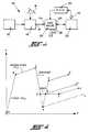
- a graph illustrating the brake apply pressure vs. time curve for an ABS as controlled by the ABS control system/method of the present inventionmay be seen by reference to Figure 2.
- the ABS valvewill assume or remain in its normally open, i.e., default, mode of operation, which is the fast fill mode of operation, and brake apply pressure will be allowed to build up until such time as conditions indicative of an actual or impending wheel-lock condition are sensed, such as at point C.
- an intermediate point, point Bwill be sensed which is a condition of a not quite eminent wheel-lock condition but for control purposes is a point wherein it is desirable that the ABS valve assume the slow fill condition until such time that pending or actual wheel-lock conditions are sensed.
- control parameter inputs to the ECU 30comprise one or more wheel speed signals.
- a specific one of the signalssuch as, for example, the highest wheel speed signal, will be the signal utilized for control purposes.
- braking pressureis allowed to rise on a fast fill basis from point A to point B.
- the ECU 30,which has circuitry and/or logic rules for calculating wheel speed acceleration from the wheel speed signal input, will compare sensed wheel speed acceleration (actually wheel speed deceleration which will be a negative wheel speed acceleration) with a first reference value, REF 1 , until such time as wheel speed acceleration is less than the first reference value REF 1 .
- REF 1is an empirically developed value which varies directly with a sensed, calculated or estimated vehicle speed.
- REF 1a value of REF 1 ranging from about -0.7G for a slowly moving vehicle to about -1.3G for a relatively rapidly moving vehicle as proven satisfactory. (G equals about 32.2 ft./sec 2 ).
- REF 2is also an empirically developed value which varies inversely with actual or estimated vehicle speed.
- REF 1is generally about one-half the absolute value of REF 2 .
- the solid line curve of apply pressure vs. timeis utilized for an ABS system of the type having a hold function whereas the dotted line curve illustrates the modifications necessary for those ABS systems not having a hold function.
- the apply pressure at the vehicle brake actuatorsas exhausted, releasing the vehicle brakes and allowing the wheels to begin to roll up to vehicle speed.
- the ABS valveis maintained in the exhaust position until such time that it becomes apparent that the brake actuators are sufficiently exhausted such that the wheels have begun to roll up to speed.
- REF 3is an empirically determined value which in the case of heavy duty trucks has a value of about 0.4G.
- a wheel acceleration of about 0.4Gis an indication that the vehicle brakes have been sufficiently released for the wheels to roll up, and by going to a hold rather than to a release position, reapplication of the brakes can occur in a more rapid fashion as the otherwise additionally release pressure will not have to be made up again.
- This ABS valveis maintained in the hold position until conditions indicative of the vehicle wheels having rolled up to almost (i.e., about 70% - 80%) vehicle speed is sensed at which point in time (See point E) a decision as to possible reapplication of the brakes and, if the brakes are to be reapplied, at what rate of pressure increase is made.
- This reapplication decision point, point Eis determined by comparing the sensed wheel speed to a reference wheel speed, REF 4 . If the sensed wheel speed exceeds the reference wheel speed REF 4 , then the control logic will make further comparisons, to be described in greater detail below, as to possible pressure reapplication and desirable presssure reapplication rate.
- REF 4has a value equal to the greater of (i) a given percentage, about 75%, of the high wheel speed, or (ii) the last calculated value of REF 4 subject to a given decay rate (about -0.5G).
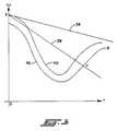
- the value of REF 4will be the value of line 38 from X to Y and the value of line 42 from Y to Z. It is noted that line 40 is the value of the measured high wheel speed which is not necessarily the wheel controlled by the ABS valve 20.
- the control logicUpon reaching the decision point E, the control logic will perform, in sequence, three comparisons of the measured wheel acceleration to different reference values to determine the appropriate action to take as to possible reapplication of the actuating pressure to the vehicle brake system.
- the measured accelerationwill be compared to a relatively high reference, REF 5 , and if acceleration to a relatively high reference, REF 5 , the ABS system will reapply the brakes at the fast fill mode of operation as represented by line EF.
- REF 5is of a relatively high value, approximately 3G, and is representative of the wheel acceleration expected on a high friction surface when the wheel speed equals REF 4 .
- the wheel speed accelerationis then compared to a lower reference value REF 6 and if the wheel acceleration is greater than REF 6 vehicle brakes are reapplied at a slow fill or modulated fill rate of pressure increase, See line EH.
- REF 6is selected at an intermediate value, say 2G, which when the vehicle speed is equal to the REF 4 would be indicative of operation on an intermediate friction surface.
- wheel accelerationis less than REF 6 , it is taken as an indication that the vehicle is operating on a relatively low friction surface and the vehicle brakes are retained in the hold position until such time as wheel acceleration is less than a relatively low reference value, REF 7 , which will have a value of about 0 to .1G which is indicative of a very low slip condition when it is relatively safe on a low friction surface to begin reapplying the brakes. At that time. point I, the brakes are reapplied in a modulated manner.
- points F and Gare determined by the same logic utilized to determine point B and C, respectively.
- the vehicle brakesupon determination of an actual or eminent wheel-lock condition, point C, the vehicle brakes will be maintained in the exhaust condition until such time, point K, until such time that (I) the sensed wheel speed is equal to or greater than REF 4 and wheel acceleration is equal to or greater than Ref 5 in which case the brakes will be reapplied on the fast fill method of operation, See K, E, F or, until such time that wheel speed is equal to or greater than REF 4 and wheel acceleration is equal to or greater than REF 6 or less than REF 7 at which point the brakes will be reapplied on the modulated or slow fill basis. See line KL.
- a control system/method for an ABS system utilizing wheel speed as the control input parameter thereofis provided with pressure reapply logic, including the timing and the rate or pressure reapplication, which is suited for either one of high friction surface, intermediate friction surface or low friction surface operation.
- fast fillmay be somewhat modulated relative to a fully opened valve and thus the rate of fill illustrated by line portion AB may be at a slightly greater increase than the rate of pressure increase illustrated by line EF.
- rate of fill illustrated by line portion ABmay be at a slightly greater increase than the rate of pressure increase illustrated by line EF.
- both the wide open and fast fill modes of operationwill be considered as substantially identical.
Landscapes
- Engineering & Computer Science (AREA)
- Transportation (AREA)
- Mechanical Engineering (AREA)
- Physics & Mathematics (AREA)
- Fluid Mechanics (AREA)
- Microelectronics & Electronic Packaging (AREA)
- Regulating Braking Force (AREA)
Description
- The present invention relates to vehicular Anti-lock Brake Systems ("ABS") and more particularly, to the control system/method for determining when, and in what manner, braking pressure should be reapplied to pressurized fluid actuated vehicular brakes which have been released in response to a sensed actual or incipient wheel-lock condition.
- Anti-lock brake systems for vehicular fluid pressure actuated brakes are well known in the prior art. Briefly, as is well known, to provide a desirable maximized combination of vehicle retardation and lateral and transverse vehicle stability, it is important to prevent and/or quickly terminate occurrences of wheel-lock up. In particular, to provide a maximized combination of vehicle retardation (i.e. braking) and vehicle stability, it is advantageous to maintain the slip rate at about twenty to forty percent (20% to 40%). Prior art vehicular ABS, and ABS valves therefor, to accomplish the above may be appreciated by reference to the following U.S. Patents Nos., the disclosures of which are incorporated by reference: 3,604,760; 3,663,070; 3,709,566; 3,747,989; 3,758,167; 3,880,474; 3,881,779; 3,917,358; 3,929,383; 4,094,556; 4,189,192; 4,511,971; 4,585,280; 4,679,866 and 4,762,375.
- The prior art ABS typically utilized an ABS valve having an inlet port and a utilization port connected in series between the brake treadle valve controlled by the operator brake pedal and the fluid operated brakes. The ABS valves also had an exhaust port and one or more controllable valve elements, usually solenoid controlled valves controlled by a microprocessor based ABS controller, to provide a fast fill, slow fill, exhaust (release) and often a hold function. The ABS valves often were operated by pulse width modulation techniques or the like to achieve the slow fill and/or hold functions.
- In operation, the inlet to the ABS valve received pressurized fluid at a pressure set by the operator's position of the brake pedal. Initially, the ABS valve remained in a fully or substantially fully open (fast fill) position, with the exhaust port closed until actual or incipient wheel-lock was sensed. The ABS valve then assumed the release (exhaust condition) to rapidly release the brakes until conditions requiring a hold or reapply operation were sensed (usually an indication that the wheels were rolling up to vehicle speed), and then the brakes were reapplied as the ABS valve reassumed a fast fill condition until a condition, such as sensing a pressure slightly less than last pressure at which a lock-up condition was sensed, was achieved, at which time the brakes were applied with a less rapidly increasing pressure as the ABS valve assumed the slow fill mode.
- Another type of brake control system/method is shown in US-PS 4 188 075. The system disclosed therein is an adaptive acceleration system for a vehicle anti-skid brake control system which effectively adapts to the coefficient of friction between the road surface and the tires of the vehicle to provide variable control of the reapplication of the brake pressure during spin up or acceleration of the wheels, for example after a skid has occurred. After the skid has occurred the system determines the degree of acceleration of the wheels and in accordance with the acceleration it controls the pressure supplied to the wheel brakes. Three different steps of pressure reduction are provided which are correlated to four different wheel accelerations.
- While the prior art ABS do provide increased vehicle retardation and/or stability, they are not totally satisfactory, as pressure sensors as well as wheel speed sensors were required, and/or the control system/method for determining at what point and at what rate of pressure increase to reapply the brakes was not satisfactory for low friction, medium friction and high friction surface conditions.
- In accordance with the present invention, the drawbacks of the prior art ABS control systems/methods have been overcome to the extent that an ABS control system/method utilizing only wheel speed, and its first derivative wheel acceleration, as control parameter inputs and responsive to sensed conditions to reapply brake pressure at a time and rate suitable for any one of low friction, medium friction and high friction surface conditions, is provided.
- The above is accomplished by not attempting to reapply brake pressure, i.e. maintaining the ABS valve in either the exhaust or hold mode, until the sensed vehicle speed is equal to or greater than a constantly variable speed reference value, Once wheel speed does equal or exceed the wheel speed reference, the pressure is either applied on a fast fill basis, applied in a slow fill basis or not reapplied until further conditions are met, and then on a slow fill basis, depending upon the sensed or calculated value of wheel acceleration.
- Accordingly, it is an object of the present invention to provide a new and improved control method/system for controlling the pressure reapply timing and rate in an ABS system utilizing only wheel speed and/or wheel acceleration as control parameter inputs.
- This and other objects and advantages of the present invention will become apparent from a reading of the following description of the preferred embodiment(s) taken in connection with the attached drawings.
- Figure 1 is a schematic representation of a typical vehicular ABS.
- Figure 2 is a graph illustrating the brake apply pressure vs. time curve(s) for the ABS control system/method of the present invention.
- Figure 3 is a graph illustrating determination of the reapply wheel speed reference value.
- ABS, i.e. anti-lock brake systems, are well known in the prior art as may be seen by reference to the above-mentioned U.S. patents. A schematic illustration of a typical vehicular ABS may be seen by reference to Figure 1.
ABS 10 includes a source of pressurizedfluid 12, which in heavy duty vehicles is typically a brake wet tank supplied with pressurized fluid by the on-board vehicle compressor, abrake treadle valve 14 which will provide pressurized fluid at itsoutlet 16 having a pressure substantially proportional to the displacement of the operator's brake pedal 1 and anABS valve 20 interposed between thetreadle valve 14 and the actuators of the pressurized fluid actuatedbrake system 22. TheABS valve 20 includes aninlet 24 connected to the outlet of thebrake treadle valve 14, a utilization port 26 fluidly connected to thevehicle brake system 22 and aport 28 connected to an exhaust, such as to atmosphere. TheABS valve 20 is controlled by a controller, such aselectronic control unit 30, which receives input signals from one or morewheel speed sensors 32. - Typically, the ABS valve will include one or more valving elements, often solenoid control valving elements, for selectively establishing or blocking fluid flow between the various ports thereof. A typical ABS valve will have a first mode of operation, often referred to as fast fill, wherein the
inlet port 24 is directly or substantially connected to the port 26 while theexhaust port 28 is blocked, a second mode of operation, often referred to as slow or modulated fill, wherein theinlet port 24 is connected to the outlet port 26 through a restricted passage and/or the exhaust port is partially opened to provide a reduced flow of pressurized fluid from thetreadle valve 14 to thebrake system 22 and a third mode of operation, often referred to as exhaust or release, wherein theinlet port 24 is blocked from the port 26 and the port 26 is connected to theexhaust port 28 for rapidly exhausting built up fluid pressure in thebrake system 22 to cause a release of the vehicle brakes. ABS valves may also have a forth mode of operation, often referred to as a hold mode, wherein port 26 is blocked to maintain the fluid pressure in the brake system actuators at a substantially constant level of pressurization. Of course, the modulated or slow fill mode of operation and/or the hold mode of operation may be achieved by a pulse width modulation control of the various ABS valve valving members. ABS valves for providing the modes of operation described above are well known to the prior art as may be seen by reference to above-mentioned U.S. patent nos. 3,880,474; 3,881,779; 3,929,383; 4,585,280 and 4,762,375; and the specific structural details of the ABS valve forms no part of the present invention. - As is also well known, the general purpose of an ABS is to improve a preselected combination of vehicle retardation and vehicle stability conditions by selective modulation of the actuating force applied to selected vehicular brakes. This is generally accomplished by sensing conditions indicative of an actual or eminent wheel-lock condition and responding thereto by releasing the vehicular brakes to allow the wheels to roll up to a given percentage of vehicle speed and to then reapply the brakes as soon as possible, often in a modulated manner, until such time as conditions indicative of actual or eminent wheel-lock condition are again sensed.
- A graph illustrating the brake apply pressure vs. time curve for an ABS as controlled by the ABS control system/method of the present invention may be seen by reference to Figure 2. Starting at initiation, of a vehicular braking operation, at point A, the ABS valve will assume or remain in its normally open, i.e., default, mode of operation, which is the fast fill mode of operation, and brake apply pressure will be allowed to build up until such time as conditions indicative of an actual or impending wheel-lock condition are sensed, such as at point C. Preferably, as is illustrated in Figure 2, an intermediate point, point B, will be sensed which is a condition of a not quite eminent wheel-lock condition but for control purposes is a point wherein it is desirable that the ABS valve assume the slow fill condition until such time that pending or actual wheel-lock conditions are sensed.
- In the control system/method of the present invention, the control parameter inputs to the
ECU 30 comprise one or more wheel speed signals. In the event that two or more wheel speed signals are utilized to control two or more braking sites as a unit, a specific one of the signals, such as, for example, the highest wheel speed signal, will be the signal utilized for control purposes. - In the ABS control system/method of present invention, upon initiation of a braking event, braking pressure is allowed to rise on a fast fill basis from point A to point B. The
ECU 30, which has circuitry and/or logic rules for calculating wheel speed acceleration from the wheel speed signal input, will compare sensed wheel speed acceleration (actually wheel speed deceleration which will be a negative wheel speed acceleration) with a first reference value, REF1, until such time as wheel speed acceleration is less than the first reference value REF1. When wheel speed acceleration falls below the REF1 value, theABS valve 20 will be caused to assume its modulated or slow fill mode of operation as may be seen by reference to line BC. REF1 is an empirically developed value which varies directly with a sensed, calculated or estimated vehicle speed. By way of example, for heavy duty vehicles, a value of REF1 ranging from about -0.7G for a slowly moving vehicle to about -1.3G for a relatively rapidly moving vehicle as proven satisfactory. (G equals about 32.2 ft./sec2). - After wheel deceleration has been found to be less than REF1, applied pressure will be allowed to build up at a modulated fill rate until such time that wheel deceleration becomes less than a second reference value REF2. When wheel speed deceleration becomes less than the REF2 value, See point C, conditions indicative of an actual or eminent wheel-lock up are believed to exist and apply pressure in the vehicle brake system actuators is immediately exhausted by causing the ABS valve to assume the exhaust mode of operations thereof. The value of REF2 is also an empirically developed value which varies inversely with actual or estimated vehicle speed. By way of example, for heavy duty vehicles, a value of REF2 of -1.5G for slowing moving vehicles to -3.0G for relatively rapidly moving vehicles is found to be acceptable. As may be seen, the absolute value of REF1 is generally about one-half the absolute value of REF2.
- Referring to Figure 2, the solid line curve of apply pressure vs. time is utilized for an ABS system of the type having a hold function whereas the dotted line curve illustrates the modifications necessary for those ABS systems not having a hold function.
- Upon sensing conditions indicative of an actual or impending wheel-lock condition, the apply pressure at the vehicle brake actuators as exhausted, releasing the vehicle brakes and allowing the wheels to begin to roll up to vehicle speed. Assuming an ABS having a hold position, the ABS valve is maintained in the exhaust position until such time that it becomes apparent that the brake actuators are sufficiently exhausted such that the wheels have begun to roll up to speed. This is sensed by comparing the wheel acceleration to a third reference value, REF3 and going from the release mode of operation to the hold mode of operation if wheel acceleration is equal or greater than See Point D. REF3 is an empirically determined value which in the case of heavy duty trucks has a value of about 0.4G. Briefly, a wheel acceleration of about 0.4G is an indication that the vehicle brakes have been sufficiently released for the wheels to roll up, and by going to a hold rather than to a release position, reapplication of the brakes can occur in a more rapid fashion as the otherwise additionally release pressure will not have to be made up again.
- This ABS valve is maintained in the hold position until conditions indicative of the vehicle wheels having rolled up to almost (i.e., about 70% - 80%) vehicle speed is sensed at which point in time (See point E) a decision as to possible reapplication of the brakes and, if the brakes are to be reapplied, at what rate of pressure increase is made. This reapplication decision point, point E, is determined by comparing the sensed wheel speed to a reference wheel speed, REF4. If the sensed wheel speed exceeds the reference wheel speed REF4, then the control logic will make further comparisons, to be described in greater detail below, as to possible pressure reapplication and desirable presssure reapplication rate.
- REF4 has a value equal to the greater of (i) a given percentage, about 75%, of the high wheel speed, or (ii) the last calculated value of REF4 subject to a given decay rate (about -0.5G). The determination of REF4 may be better appreciated by referenced to Figure 3 which is a graph of wheel speed vs. time. Assuming a braking event occurs at time 0 when wheel speed = X,
line 36 will represent the 0 slip wheel speed at assumed vehicle velocity,line 38 will represent previously calculated REF4 values decayed at a rate of approximately 0.5G,line 40 will represent measured wheel velocity whileline 42 will represent a given percentage, about 75%, of measured wheel velocity. In this very typical example, the value of REF4 will be the value ofline 38 from X to Y and the value ofline 42 from Y to Z. It is noted thatline 40 is the value of the measured high wheel speed which is not necessarily the wheel controlled by theABS valve 20. - Upon reaching the decision point E, the control logic will perform, in sequence, three comparisons of the measured wheel acceleration to different reference values to determine the appropriate action to take as to possible reapplication of the actuating pressure to the vehicle brake system. First, the measured acceleration will be compared to a relatively high reference, REF5, and if acceleration to a relatively high reference, REF5, the ABS system will reapply the brakes at the fast fill mode of operation as represented by line EF. REF5 is of a relatively high value, approximately 3G, and is representative of the wheel acceleration expected on a high friction surface when the wheel speed equals REF4. When the wheel acceleration is not equal to or greater than REF5 the wheel speed acceleration is then compared to a lower reference value REF6 and if the wheel acceleration is greater than REF6 vehicle brakes are reapplied at a slow fill or modulated fill rate of pressure increase, See line EH. REF6 is selected at an intermediate value, say 2G, which when the vehicle speed is equal to the REF4 would be indicative of operation on an intermediate friction surface. If the wheel acceleration is less than REF6, it is taken as an indication that the vehicle is operating on a relatively low friction surface and the vehicle brakes are retained in the hold position until such time as wheel acceleration is less than a relatively low reference value, REF7, which will have a value of about 0 to .1G which is indicative of a very low slip condition when it is relatively safe on a low friction surface to begin reapplying the brakes. At that time. point I, the brakes are reapplied in a modulated manner.
- It is noted that points F and G are determined by the same logic utilized to determine point B and C, respectively.
- Should the
ABS valve 20 in the ABS system controlled by the control system/method of the present invention not have a hold mode of operation, upon determination of an actual or eminent wheel-lock condition, point C, the vehicle brakes will be maintained in the exhaust condition until such time, point K, until such time that (I) the sensed wheel speed is equal to or greater than REF4 and wheel acceleration is equal to or greater than Ref5 in which case the brakes will be reapplied on the fast fill method of operation, See K, E, F or, until such time that wheel speed is equal to or greater than REF4 and wheel acceleration is equal to or greater than REF6 or less than REF7 at which point the brakes will be reapplied on the modulated or slow fill basis. See line KL. - It may be seen by reference to the above, that a control system/method for an ABS system utilizing wheel speed as the control input parameter thereof is provided with pressure reapply logic, including the timing and the rate or pressure reapplication, which is suited for either one of high friction surface, intermediate friction surface or low friction surface operation.
- It is noted that the fast fill may be somewhat modulated relative to a fully opened valve and thus the rate of fill illustrated by line portion AB may be at a slightly greater increase than the rate of pressure increase illustrated by line EF. However, for purposes of this description, both the wide open and fast fill modes of operation will be considered as substantially identical.
- While the preferred form of the present invention has been described with a certain degree of particularly, it is understood that various modifications thereof are possible without departing from the scope of the invention as hereinafter claimed.
Claims (20)
- An ABS control method for controlling a vehicular ABS of the type comprising an ABS valve (20) connected in series between a treadle valve device (14) and one or more fluid pressure operated vehicle brake actuators (22),said ABS valve (20) controlled by a control unit (30) having means for receiving inputs indicative of the rotational speed of one or more vehicle wheels, means to sense or determine angular acceleration of said one or more vehicle wheels and predetermined logic rules for processing said sensed or calculated control parameters and for issuing command output signals to said ABS valve (20),said ABS valve (20) having at least three positions a relatively fast fill position (A-B) wherein all or substantially all pressurized fluid from said treadle valve (14) is passed to said brake actuators, a relatively slow fill position (B-C) wherein a reduced modulated amount of pressurized fluid is passed to said brake actuators and an exhaust position (C-D) wherein fluid pressure acting on said brake actuators is exhausted to cause the release of said vehicular brakes,said control unit effective upon sensing conditions indicative of an actual or incipient wheel-lock conditions (C) to cause said ABS valve (20) to assume the exhaust position thereof, said method including the steps of:after the ABS valve (20) has been caused to assume said exhaust position, preventing an increase in the pressurization of pressurized fluid applied to said brake actuators until sensed wheel rotational velocity exceeds a first reference value (REF4) then, when sensed wheel rotational velocity exceeds said first reference value (REF4) causing said ABS valve (20) to assume the fast fill position thereof if wheel rotational acceleration exceeds a second reference value (REF5), causing said ABS valve (20) to assume the relatively slow fill position thereof if wheel rotational acceleration is less than said second reference value (REF5) but greater than a third reference value (REF6), and if wheel angular acceleration is less than said third reference value (REF6) continuing to prevent an increase in pressurization of said fluid until wheel angular acceleration is less than a fourth reference value (REF7) then, when wheel acceleration is less than said fourth reference value (REF7), causing said ABS valve (20) to assume the relativly slow fill position thereof, said second reference (REF5) value being greater than said third reference value (REF6) and said third reference (REF6) value being greater than said fourth reference value (REF7).
- The control method of claim 1 wherein said first reference value (REF4) is the greater of (i) a given percentage of the sensed wheel rotational velocity of the fastest rotating wheel or (ii) the last calculated value of the first reference value (REF4) decayed at a predetermined rate.
- The control method of claim 2 wherein said predetermined rate is approximately -0.5g.
- The control method of claim 3 wherein said control unit (30) receives input signals indicative of the rotational velocity of two or more vehicular wheels and the rotational speed of the fastest turning wheel is compared to the first reference (REF4) and the rotational acceleration of the fastest turning wheel is compared to the second (REF5), third (REF6) and/or fourth (REF7) references.
- The control method of claim 3 wherein said control unit (30) receives input signals indicative of the rotational speed of two or more wheels and the rotational speed of the slowest turning wheel is compared to the first reference (REF4) and the rotational acceleration of the slowest turning wheel is compared to the second (REF5), third (REF6) and/or fourth (REF7) references.
- The control method of claim 3 wherein said control unit (30) receives input signals indicative of the rotational speed of more than one wheel and an average rotational speed is compared to the first reference (REF4) and an average rotational acceleration as compared to the second (REF5), third (REF6) and/or fourth (REF7) references.
- The control method of claims 1, 2, 3, 4, 5 or 6, wherein the second reference (REF5), third reference (REF6), or fourth reference (REF7), respectively, are wheel speed accelerations indicative of relatively high friction surface, relatively intermediate surface friction, and relatively low friction surfaces, respectively.
- The control method of claim 7 wherein said second reference is about g, said third reference (REF6) is about 2g, and said first reference (REF4) is about 0.1 - 0.0g.
- The control method of claims 1, 2, 3, 4, 5 or 6 wherein said ABS valve (20) has a selectable hold position wherein the level of pressurization of the actuating fluid in the brake actuators is maintains at a substantially constant level, said ABS valve (20) caused to assume said hold position from said exhaust position when said wheel acceleration is greater than a fifth reference value (REF3) said fifth reference value (REF3) greater than said fourth reference value (REF7) and less than said third reference value (REF6)
- The control method of claim 9 wherein said fifth reference value (REF3) is in the range of .06 - 0.03g.
- An ABS control system for controlling a vehicular ABS of the type comprising an ABS valve (20) connected in series between a treadle valve device (14) and one or more fluid pressure operated vehicle brake actuators (22),said ABS valve (20) controlled by a control unit (30) having means for receiving inputs indicative of the rotational speed of one or more vehicle wheels, means to sense or determine angular acceleration of said one or more vehicle wheels and predetermined logic rules for processing said sensed or calculated control parameters and for issuing command output signals to said ABS valve (20),said ABS valve (20) having at least three positions, a relatively fast fill position (A-B) wherein all or substantially all pressurized fluid from said treadle valve (14) is passed to said brake actuators, the relatively slow fill position (B-C) wherein a reduced modulated amount of pressurized fluid is passed to said brake actuators and an exhaust position (C-D) wherein fluid pressure acting on said brake actuators is exhausted to cause the release of said vehicular brakes,said control unit effective upon sensing conditions indicative of an actual or incipient wheel-lock condition (C) to cause said ABS valve (20) to assume the exhaust position thereof, said control system including:means effective, after the ABS valve (20) has been caused to assume said exhaust position, for preventing an increase in the pressurization of pressurized fluid applied to said brake actuators until sensed wheel rotational velocity exceeds a first reference value (REF4) then, when sensed wheel rotational velocity exceeds said first reference value (REF4) for causing said ABS valve (20) to assume the fast fill position thereof if wheel rotational acceleration exceeds a second reference value (REF5), for causing said ABS valve (20) to assume the relatively slow fill position thereof if wheel rotational acceleration is less than said second reference value (REF5) but greater than a third reference value (REF6), and if wheel angular acceleration is less than said third reference value (REF6) for continuing to prevent an increase in pressurization of said fluid until wheel angular acceleration is less than a fourth reference value (REF7) then, when wheel acceleration is less than said fourth reference value (REF7), for causing said ABS valve (20) to assume the relatively slow fill condition thereof, said second reference value (REF5) being greater than said third reference value (REF6) and said third reference value (REF6) being greater than said fourth reference value (REF7).
- The control system of claim 11 wherein said first reference value (REF4) is the greater of (i) a given percentage of the sensed wheel rotational velocity of the fastest rotating wheel or (ii) the last calculated value of the first reference value (REF4) decayed at a predetermined rate.
- The control system of claim 12 wherein said predetermined rate is approximately -0.5g.
- The control system of claim 13 wherein said control unit (30) receives input signals indicative of the rotational velocity of two or more vehicular wheels and the rotational speed of the fastest turning wheel is compared to the first reference (REF4) and the rotational acceleration of the fastest turning wheel is compared to the second (REF5), third (REF6) and/or fourth (REF7) references.
- The control system of claim 13 wherein said control unit (30) receives input signals indicative of the rotational speed of two or more wheels and the rotational speed of the slowest turning wheel is compared to the first reference (REF4) and the rotational acceleration of the slowest turning wheel is compared to the second (REF5), third (REF6) and/or fourth (REF7) references.
- The control system of claim 13 wherein said control unit (30) receives input signals indicative of the rotational speed of more than one wheel and an average rotational speed is compared to the first reference (REF4) and an average rotational acceleration as compared to the second (REF5), third (REF6) and/or fourth (REF7) references.
- The control system of claim 11, 12, 13, 14, 15 or 16, wherein the second reference (REF5), third reference (REF6) or fourth reference (REF7), respectively, are wheel speed accelerations indicative of relatively high friction surface, relatively intermediate surface friction, and relatively low friction surfaces, respectively.
- The control system of claim 17 wherein said second reference (REF5) is about g, said third reference (REF6) is about g, and said first reference is about 0.1 - 0.0g.
- The control system of claims 11, 12, 13, 14, 15 or 16 wherein said ABS valve (20) has a selectable hold position wherein the level of pressurization of the actuating fluid in the brake actuators is maintained at a substantially constant level, said ABS valve (20) caused to assume said hold position from said exhaust position when said wheel acceleration is greater than a fifth reference value (REF3), said fifth reference value (REF3) greater than said fourth reference value (REF7) and less than said third reference value (REF6).
- The control system of claim 19, wherein said fifth reference value (REF3) is in the range of 0.06 - 0.03g.
Applications Claiming Priority (2)
| Application Number | Priority Date | Filing Date | Title |
|---|---|---|---|
| US420802 | 1989-10-12 | ||
| US07/420,802US5071200A (en) | 1989-10-12 | 1989-10-12 | Abs pressure reapply logic |
Publications (3)
| Publication Number | Publication Date |
|---|---|
| EP0422515A2 EP0422515A2 (en) | 1991-04-17 |
| EP0422515A3 EP0422515A3 (en) | 1994-03-09 |
| EP0422515B1true EP0422515B1 (en) | 1996-12-18 |
Family
ID=23667904
Family Applications (1)
| Application Number | Title | Priority Date | Filing Date |
|---|---|---|---|
| EP90119125AExpired - LifetimeEP0422515B1 (en) | 1989-10-12 | 1990-10-05 | ABS pressure reapply logic |
Country Status (8)
| Country | Link |
|---|---|
| US (1) | US5071200A (en) |
| EP (1) | EP0422515B1 (en) |
| JP (1) | JPH03153452A (en) |
| KR (1) | KR960003119B1 (en) |
| AU (1) | AU629146B2 (en) |
| BR (1) | BR9005309A (en) |
| CA (1) | CA2026932C (en) |
| DE (1) | DE69029451T2 (en) |
Families Citing this family (16)
| Publication number | Priority date | Publication date | Assignee | Title |
|---|---|---|---|---|
| DE4208048A1 (en)* | 1992-03-13 | 1993-09-16 | Kugelfischer G Schaefer & Co | ANTI-BLOCKING CONTROL SYSTEM FOR MOTOR VEHICLES |
| US5328254A (en)* | 1992-04-29 | 1994-07-12 | Eaton Corporation | Method and system for controlling brake pressure under low Mu braking surface conditions in a vehicular ABS |
| DE4215350A1 (en)* | 1992-05-09 | 1993-11-11 | Kugelfischer G Schaefer & Co | Anti-lock control system |
| US5382086A (en)* | 1994-05-03 | 1995-01-17 | Kelsey-Hayes Company | Vehicular antilock brake system incorporating improved adaptive control feature |
| JP3545060B2 (en)* | 1994-09-16 | 2004-07-21 | トキコ株式会社 | Anti-skid control method and anti-skid control device |
| EP0786389B1 (en)* | 1996-01-23 | 2002-06-12 | WABCO GmbH & Co. OHG | Procedure for rebuilding the pressure in a vehicle with an anti-lock system |
| WO1999033688A2 (en)* | 1997-12-30 | 1999-07-08 | Kelsey-Hayes Company | Algorithm for preventing wheel speed sneakdown on a low mu surface |
| US6371573B1 (en)* | 2000-07-31 | 2002-04-16 | Robert Bosch Corporation | Special control mode for one-solenoid valves |
| US7415341B2 (en)* | 2003-12-23 | 2008-08-19 | Bendix Commercial Vehicle Systems Llc | Control module for single 3/2 solenoid controlled relay valve |
| EP2311704B1 (en)* | 2009-10-16 | 2013-02-27 | Yamaha Hatsudoki Kabushiki Kaisha | Braking system for motorcycle |
| JP5123917B2 (en)* | 2009-10-19 | 2013-01-23 | 日信工業株式会社 | Brake hydraulic pressure control device for vehicles |
| US20150084402A1 (en)* | 2013-09-26 | 2015-03-26 | Bendix Commercial Vehicle Systems Llc | Automatic traction relay valve diagnostic using pressure transducer feedback |
| US10723334B2 (en) | 2017-03-28 | 2020-07-28 | Polaris Industries Inc. | Anti-lock brake system for all-terrain vehicle |
| MX2020005177A (en) | 2017-11-22 | 2020-08-20 | Polaris Inc | Switchable anti-lock braking system for utility vehicle. |
| CA3098862A1 (en) | 2018-05-02 | 2019-11-07 | Polaris Industries Inc. | Operating modes using a braking system for an all terrain vehicle |
| US11618422B2 (en) | 2018-11-14 | 2023-04-04 | Polaris Industries Inc. | Operating modes using a braking system for an all terrain vehicle |
Family Cites Families (16)
| Publication number | Priority date | Publication date | Assignee | Title |
|---|---|---|---|---|
| DE1655454A1 (en)* | 1967-10-28 | 1971-08-12 | Teldix Gmbh | Anti-lock control system suitable for pressurized vehicle brakes |
| US4094556A (en)* | 1968-04-24 | 1978-06-13 | Nippondenso Kabushiki Kaisha | Anti-skid system for a vehicle |
| DE2146825C2 (en)* | 1971-09-18 | 1982-11-11 | Robert Bosch Gmbh, 7000 Stuttgart | Anti-lock control arrangement for pressure medium-actuated vehicle brakes |
| JPS5314708B2 (en)* | 1972-08-31 | 1978-05-19 | ||
| DE2349681A1 (en)* | 1973-10-03 | 1975-04-10 | Wabco Westinghouse Gmbh | ANTI-SKID CONTROL SYSTEM FOR PRESSURE-ACTUATED VEHICLE BRAKES |
| US3929383A (en)* | 1974-04-08 | 1975-12-30 | Eaton Corp | Skid control system including a relay compensator valve for rapid brake pressure re-application followed by slower rate of pressure re-application |
| US4188075A (en)* | 1978-06-16 | 1980-02-12 | The B. F. Goodrich Company | Adaptive acceleration system for vehicle skid control systems |
| DE3119144C2 (en)* | 1981-05-14 | 1985-01-17 | FAG Kugelfischer Georg Schäfer KGaA, 8720 Schweinfurt | Anti-lock hydraulic vehicle braking system |
| GB2135745B (en)* | 1983-02-26 | 1987-01-07 | Bosch Gmbh Robert | Circuit for controlling the brake pressure in anti-lock vehicle brake systems |
| JPH064411B2 (en)* | 1985-01-25 | 1994-01-19 | 本田技研工業株式会社 | Antilock braking system |
| US4741580A (en)* | 1985-08-02 | 1988-05-03 | Akebono Brake Industry Co., Ltd. | Anti-skid control system for motor vehicle |
| DE3644324A1 (en)* | 1985-12-23 | 1987-07-02 | Nissan Motor | ANTI-BLOCK BRAKE CONTROL SYSTEM |
| JPH0688531B2 (en)* | 1985-12-27 | 1994-11-09 | 曙ブレーキ工業株式会社 | Anti-skidding control method |
| SU1423442A1 (en)* | 1986-11-06 | 1988-09-15 | Харьковский Автомобильно-Дорожный Институт Им.Комсомола Украины | Method of regulating pressure in antiskid sistem brake actuator |
| EP0331133B1 (en)* | 1988-02-29 | 1996-07-17 | Nissan Motor Co., Ltd. | Anti-skid brake control system with capability of eliminating influence of noise in derivation of wheel acceleration data |
| JPH01275251A (en)* | 1988-04-28 | 1989-11-02 | Nissan Motor Co Ltd | anti-skid control device |
- 1989
- 1989-10-12USUS07/420,802patent/US5071200A/ennot_activeExpired - Lifetime
- 1990
- 1990-10-04CACA002026932Apatent/CA2026932C/ennot_activeExpired - Fee Related
- 1990-10-05EPEP90119125Apatent/EP0422515B1/ennot_activeExpired - Lifetime
- 1990-10-05DEDE69029451Tpatent/DE69029451T2/ennot_activeExpired - Fee Related
- 1990-10-12KRKR1019900016181Apatent/KR960003119B1/ennot_activeExpired - Fee Related
- 1990-10-12JPJP2275097Apatent/JPH03153452A/enactivePending
- 1990-10-12BRBR909005309Apatent/BR9005309A/ennot_activeIP Right Cessation
- 1990-10-12AUAU64541/90Apatent/AU629146B2/ennot_activeCeased
Also Published As
| Publication number | Publication date |
|---|---|
| CA2026932C (en) | 1997-12-30 |
| CA2026932A1 (en) | 1991-04-13 |
| EP0422515A3 (en) | 1994-03-09 |
| BR9005309A (en) | 1991-09-17 |
| DE69029451D1 (en) | 1997-01-30 |
| AU629146B2 (en) | 1992-09-24 |
| AU6454190A (en) | 1991-04-18 |
| KR910009515A (en) | 1991-06-28 |
| JPH03153452A (en) | 1991-07-01 |
| US5071200A (en) | 1991-12-10 |
| DE69029451T2 (en) | 1997-07-10 |
| KR960003119B1 (en) | 1996-03-05 |
| EP0422515A2 (en) | 1991-04-17 |
Similar Documents
| Publication | Publication Date | Title |
|---|---|---|
| EP0422515B1 (en) | ABS pressure reapply logic | |
| US6081761A (en) | Automatic deceleration control method and apparatus for a vehicle | |
| EP1721796B1 (en) | Pressure boost for vehicle rear brake circuits | |
| US4511971A (en) | Antilocking brake system | |
| GB2242492A (en) | Improvements in and relating to anti-lock brake systems | |
| US4651281A (en) | Antiskid control with wheel-speed difference compensation | |
| US6203121B1 (en) | Coefficient of friction peak estimation apparatus | |
| JP3812017B2 (en) | Vehicle motion control device | |
| KR970001876B1 (en) | Vehicle brake control system | |
| EP0176785B1 (en) | Wheel slip controlling system | |
| JP3425727B2 (en) | Automatic braking system for vehicles | |
| JP2500857B2 (en) | Anti-skidding control device | |
| JP3653774B2 (en) | Vehicle stability control device | |
| US5433513A (en) | Anti-skid control device for vehicles | |
| JPH06144178A (en) | Braking force distribution control device | |
| EP0554879B1 (en) | Anti-skid brake system for wheeled vehicle and control method thereof | |
| JP2689405B2 (en) | Anti-lock control device | |
| JP3939859B2 (en) | Step determination device for vehicle road surface | |
| JP3517954B2 (en) | Vehicle anti-skid control device | |
| JP3405387B2 (en) | Vehicle braking force control device | |
| JPH11189148A (en) | Travel control device for four-wheel drive vehicles | |
| JPH068959Y2 (en) | Brake device for vehicle | |
| JP3696259B2 (en) | Braking force control device | |
| JPH07108918A (en) | Vehicle hydraulic control device | |
| JP2000344089A (en) | Vehicle braking force control device |
Legal Events
| Date | Code | Title | Description |
|---|---|---|---|
| PUAI | Public reference made under article 153(3) epc to a published international application that has entered the european phase | Free format text:ORIGINAL CODE: 0009012 | |
| AK | Designated contracting states | Kind code of ref document:A2 Designated state(s):DE FR GB IT SE | |
| PUAL | Search report despatched | Free format text:ORIGINAL CODE: 0009013 | |
| AK | Designated contracting states | Kind code of ref document:A3 Designated state(s):DE FR GB IT SE | |
| 17P | Request for examination filed | Effective date:19940817 | |
| 17Q | First examination report despatched | Effective date:19950329 | |
| GRAG | Despatch of communication of intention to grant | Free format text:ORIGINAL CODE: EPIDOS AGRA | |
| GRAH | Despatch of communication of intention to grant a patent | Free format text:ORIGINAL CODE: EPIDOS IGRA | |
| GRAH | Despatch of communication of intention to grant a patent | Free format text:ORIGINAL CODE: EPIDOS IGRA | |
| GRAA | (expected) grant | Free format text:ORIGINAL CODE: 0009210 | |
| AK | Designated contracting states | Kind code of ref document:B1 Designated state(s):DE FR GB IT SE | |
| REF | Corresponds to: | Ref document number:69029451 Country of ref document:DE Date of ref document:19970130 | |
| ITF | It: translation for a ep patent filed | ||
| ET | Fr: translation filed | ||
| PLBE | No opposition filed within time limit | Free format text:ORIGINAL CODE: 0009261 | |
| STAA | Information on the status of an ep patent application or granted ep patent | Free format text:STATUS: NO OPPOSITION FILED WITHIN TIME LIMIT | |
| 26N | No opposition filed | ||
| PGFP | Annual fee paid to national office [announced via postgrant information from national office to epo] | Ref country code:GB Payment date:19981001 Year of fee payment:9 | |
| PGFP | Annual fee paid to national office [announced via postgrant information from national office to epo] | Ref country code:FR Payment date:19981006 Year of fee payment:9 | |
| PGFP | Annual fee paid to national office [announced via postgrant information from national office to epo] | Ref country code:SE Payment date:19981007 Year of fee payment:9 | |
| PGFP | Annual fee paid to national office [announced via postgrant information from national office to epo] | Ref country code:DE Payment date:19981028 Year of fee payment:9 | |
| PG25 | Lapsed in a contracting state [announced via postgrant information from national office to epo] | Ref country code:GB Free format text:LAPSE BECAUSE OF NON-PAYMENT OF DUE FEES Effective date:19991005 | |
| PG25 | Lapsed in a contracting state [announced via postgrant information from national office to epo] | Ref country code:SE Free format text:THE PATENT HAS BEEN ANNULLED BY A DECISION OF A NATIONAL AUTHORITY Effective date:19991030 | |
| GBPC | Gb: european patent ceased through non-payment of renewal fee | Effective date:19991005 | |
| EUG | Se: european patent has lapsed | Ref document number:90119125.4 | |
| PG25 | Lapsed in a contracting state [announced via postgrant information from national office to epo] | Ref country code:FR Free format text:LAPSE BECAUSE OF NON-PAYMENT OF DUE FEES Effective date:20000630 | |
| PG25 | Lapsed in a contracting state [announced via postgrant information from national office to epo] | Ref country code:DE Free format text:LAPSE BECAUSE OF NON-PAYMENT OF DUE FEES Effective date:20000801 | |
| REG | Reference to a national code | Ref country code:FR Ref legal event code:ST | |
| PG25 | Lapsed in a contracting state [announced via postgrant information from national office to epo] | Ref country code:IT Free format text:LAPSE BECAUSE OF NON-PAYMENT OF DUE FEES;WARNING: LAPSES OF ITALIAN PATENTS WITH EFFECTIVE DATE BEFORE 2007 MAY HAVE OCCURRED AT ANY TIME BEFORE 2007. THE CORRECT EFFECTIVE DATE MAY BE DIFFERENT FROM THE ONE RECORDED. Effective date:20051005 |