EP0418964B1 - Record carrier, method of and information recording device for obtaining such record carriers, and information recording device comprising anti-copy means to inhibit unauthorized copying - Google Patents
Record carrier, method of and information recording device for obtaining such record carriers, and information recording device comprising anti-copy means to inhibit unauthorized copyingDownload PDFInfo
- Publication number
- EP0418964B1 EP0418964B1EP90202448AEP90202448AEP0418964B1EP 0418964 B1EP0418964 B1EP 0418964B1EP 90202448 AEP90202448 AEP 90202448AEP 90202448 AEP90202448 AEP 90202448AEP 0418964 B1EP0418964 B1EP 0418964B1
- Authority
- EP
- European Patent Office
- Prior art keywords
- copy
- information
- bits
- pattern
- recording device
- Prior art date
- Legal status (The legal status is an assumption and is not a legal conclusion. Google has not performed a legal analysis and makes no representation as to the accuracy of the status listed.)
- Expired - Lifetime
Links
Images


Classifications
- G—PHYSICS
- G11—INFORMATION STORAGE
- G11B—INFORMATION STORAGE BASED ON RELATIVE MOVEMENT BETWEEN RECORD CARRIER AND TRANSDUCER
- G11B20/00—Signal processing not specific to the method of recording or reproducing; Circuits therefor
- G11B20/10—Digital recording or reproducing
- G—PHYSICS
- G11—INFORMATION STORAGE
- G11B—INFORMATION STORAGE BASED ON RELATIVE MOVEMENT BETWEEN RECORD CARRIER AND TRANSDUCER
- G11B20/00—Signal processing not specific to the method of recording or reproducing; Circuits therefor
- G11B20/00086—Circuits for prevention of unauthorised reproduction or copying, e.g. piracy
- G—PHYSICS
- G11—INFORMATION STORAGE
- G11B—INFORMATION STORAGE BASED ON RELATIVE MOVEMENT BETWEEN RECORD CARRIER AND TRANSDUCER
- G11B27/00—Editing; Indexing; Addressing; Timing or synchronising; Monitoring; Measuring tape travel
- G11B27/02—Editing, e.g. varying the order of information signals recorded on, or reproduced from, record carriers
- G11B27/031—Electronic editing of digitised analogue information signals, e.g. audio or video signals
- G11B27/034—Electronic editing of digitised analogue information signals, e.g. audio or video signals on discs
- G—PHYSICS
- G11—INFORMATION STORAGE
- G11B—INFORMATION STORAGE BASED ON RELATIVE MOVEMENT BETWEEN RECORD CARRIER AND TRANSDUCER
- G11B27/00—Editing; Indexing; Addressing; Timing or synchronising; Monitoring; Measuring tape travel
- G11B27/10—Indexing; Addressing; Timing or synchronising; Measuring tape travel
- G11B27/19—Indexing; Addressing; Timing or synchronising; Measuring tape travel by using information detectable on the record carrier
- G11B27/28—Indexing; Addressing; Timing or synchronising; Measuring tape travel by using information detectable on the record carrier by using information signals recorded by the same method as the main recording
- G11B27/30—Indexing; Addressing; Timing or synchronising; Measuring tape travel by using information detectable on the record carrier by using information signals recorded by the same method as the main recording on the same track as the main recording
- G11B27/3027—Indexing; Addressing; Timing or synchronising; Measuring tape travel by using information detectable on the record carrier by using information signals recorded by the same method as the main recording on the same track as the main recording used signal is digitally coded
- G11B27/3063—Subcodes
- G—PHYSICS
- G11—INFORMATION STORAGE
- G11B—INFORMATION STORAGE BASED ON RELATIVE MOVEMENT BETWEEN RECORD CARRIER AND TRANSDUCER
- G11B7/00—Recording or reproducing by optical means, e.g. recording using a thermal beam of optical radiation by modifying optical properties or the physical structure, reproducing using an optical beam at lower power by sensing optical properties; Record carriers therefor
- G11B7/28—Re-recording, i.e. transcribing information from one optical record carrier on to one or more similar or dissimilar record carriers
- G—PHYSICS
- G06—COMPUTING OR CALCULATING; COUNTING
- G06F—ELECTRIC DIGITAL DATA PROCESSING
- G06F21/00—Security arrangements for protecting computers, components thereof, programs or data against unauthorised activity
- G06F21/10—Protecting distributed programs or content, e.g. vending or licensing of copyrighted material ; Digital rights management [DRM]
- G06F21/109—Protecting distributed programs or content, e.g. vending or licensing of copyrighted material ; Digital rights management [DRM] by using specially-adapted hardware at the client
- G—PHYSICS
- G06—COMPUTING OR CALCULATING; COUNTING
- G06F—ELECTRIC DIGITAL DATA PROCESSING
- G06F2211/00—Indexing scheme relating to details of data-processing equipment not covered by groups G06F3/00 - G06F13/00
- G06F2211/007—Encryption, En-/decode, En-/decipher, En-/decypher, Scramble, (De-)compress
- G—PHYSICS
- G11—INFORMATION STORAGE
- G11B—INFORMATION STORAGE BASED ON RELATIVE MOVEMENT BETWEEN RECORD CARRIER AND TRANSDUCER
- G11B20/00—Signal processing not specific to the method of recording or reproducing; Circuits therefor
- G11B20/10—Digital recording or reproducing
- G11B20/10527—Audio or video recording; Data buffering arrangements
- G11B2020/10537—Audio or video recording
- G11B2020/10592—Audio or video recording specifically adapted for recording or reproducing multichannel signals
- G—PHYSICS
- G11—INFORMATION STORAGE
- G11B—INFORMATION STORAGE BASED ON RELATIVE MOVEMENT BETWEEN RECORD CARRIER AND TRANSDUCER
- G11B2220/00—Record carriers by type
- G11B2220/20—Disc-shaped record carriers
- G11B2220/21—Disc-shaped record carriers characterised in that the disc is of read-only, rewritable, or recordable type
- G11B2220/215—Recordable discs
- G11B2220/218—Write-once discs
- G—PHYSICS
- G11—INFORMATION STORAGE
- G11B—INFORMATION STORAGE BASED ON RELATIVE MOVEMENT BETWEEN RECORD CARRIER AND TRANSDUCER
- G11B2220/00—Record carriers by type
- G11B2220/20—Disc-shaped record carriers
- G11B2220/25—Disc-shaped record carriers characterised in that the disc is based on a specific recording technology
- G11B2220/2537—Optical discs
- G11B2220/2545—CDs
- G—PHYSICS
- G11—INFORMATION STORAGE
- G11B—INFORMATION STORAGE BASED ON RELATIVE MOVEMENT BETWEEN RECORD CARRIER AND TRANSDUCER
- G11B2220/00—Record carriers by type
- G11B2220/90—Tape-like record carriers
- G—PHYSICS
- G11—INFORMATION STORAGE
- G11B—INFORMATION STORAGE BASED ON RELATIVE MOVEMENT BETWEEN RECORD CARRIER AND TRANSDUCER
- G11B2220/00—Record carriers by type
- G11B2220/90—Tape-like record carriers
- G11B2220/91—Helical scan format, wherein tracks are slightly tilted with respect to tape direction, e.g. VHS, DAT, DVC, AIT or exabyte
- G11B2220/913—Digital audio tape [DAT] format
- G—PHYSICS
- G11—INFORMATION STORAGE
- G11B—INFORMATION STORAGE BASED ON RELATIVE MOVEMENT BETWEEN RECORD CARRIER AND TRANSDUCER
- G11B27/00—Editing; Indexing; Addressing; Timing or synchronising; Monitoring; Measuring tape travel
- G11B27/02—Editing, e.g. varying the order of information signals recorded on, or reproduced from, record carriers
- G11B27/031—Electronic editing of digitised analogue information signals, e.g. audio or video signals
- G11B27/032—Electronic editing of digitised analogue information signals, e.g. audio or video signals on tapes
Definitions
- Such a record carriermay be, for example, an optically readable disc, such as a "Compact Disc” or a magnetic tape, such as "DAT” cassette tapes.
- An optically readable discsuch as a "Compact Disc” or a magnetic tape, such as "DAT” cassette tapes.
- the circuit shown in Fig. 8operates as follows. If the logic value of the interface "copy” bit changes the logic value of the signal on the input of the flip-flop 91 at the instant at which the first "copy” bit of changed logic value reaches the input of the flip-flop 91 will no longer correspond to the logic value of the signal on the output of the flip-flop 91. In that case the logic value of the output of the Exclusive-OR gate becomes a logic "1" value. This value is latched in the flip-flop 92, after which the detection signal Vd also assumes the logic "1" value.
Landscapes
- Engineering & Computer Science (AREA)
- Multimedia (AREA)
- Computer Security & Cryptography (AREA)
- Signal Processing (AREA)
- Software Systems (AREA)
- Theoretical Computer Science (AREA)
- General Engineering & Computer Science (AREA)
- Physics & Mathematics (AREA)
- Computer Hardware Design (AREA)
- General Physics & Mathematics (AREA)
- Technology Law (AREA)
- Signal Processing For Digital Recording And Reproducing (AREA)
- Television Signal Processing For Recording (AREA)
- Storage Device Security (AREA)
- Indexing, Searching, Synchronizing, And The Amount Of Synchronization Travel Of Record Carriers (AREA)
- Management Or Editing Of Information On Record Carriers (AREA)
- Optical Recording Or Reproduction (AREA)
Description
- The invention relates to a record carrier carrying main information together with a series of subcode frames which each comprise a "copy" bit.
- The invention further relates to a method of obtaining a record carrier, information, together with a series of subcode frames which each comprise a "copy" bit being recorded on the record carrier.
- The invention further relates to an information recording device for obtaining a record carrier, which device is constructed to record on the record carrier main information together with a series of subcode frames which each comprise a "copy" bit.
- Finally, the invention relates to an information recording device for recording main information received together with a series of subcode frames which each comprise a "copy" bit, which device comprises anti-copy means to inhibit unauthorized copying of the received information, which anti-copy means comprise decision means for deciding whether recording of the received information is permissible depending upon the logic values of the received "copy" bits, and means responsive to a decision that recording is not permissible to inhibit recording.
- Record carriers carrying which digitised audio information have been available for a considerable time. Such a record carrier may be, for example, an optically readable disc, such as a "Compact Disc" or a magnetic tape, such as "DAT" cassette tapes. The advantage of digitised audio information is the extremely high quality.
- Another property of digitised information is that it can be copied to an almost unlimited extent without any significant loss of quality.
- This last-mentioned property constitutes a substantial problem when consumer equipment by means of which digital audio information cannot only be reproduced but can also be recorded is to be put on the market.
- This is because such an apparatus makes for large scale copyright infringement by the customer in that the contents of a record carrier carrying digitised audio information is simply copied.
- Since there is no loss of quality as a result of copying there is hardly any reason for the consumer to purchase a comparatively expensive original which is subject to copyright if the original or a copy thereof is available. All this leads to a substantial loss of copyright revenues.
- A recent copy protection method which mitigates the above drawbacks is known as the "Solocopy" copy-protection system. This method allows only first-generation copies to be made of record carriers carrying original information. In the "Solocopy" copy-protection system it is assumed that the digital information to be recorded complies with a standard-audio interface format, as described in, for example, the first edition (1989.03) of the IEC-958 standard. Such a format comprises mairi information channels and subcode information channels. The subcode information signal includes a "copy" bit indicating whether the information may be copied freely, and a category code indicating the source of the recorded information.
- In accordance with the "Solocopy" copy protection method it is ascertained by means of the category code and the "copy" bit whether the applied information may be copied. For example, copying is always allowed if the category code indicates that the information originates from a CD player. This is based on the assumption that a CD player is only capable of playing CDs of the read-only type. However, in the meantime, CD recording devices have been developed by means of which information can be recorded on a record carrier, which can subsequently be read by a standard CD player for reading CDs of the read-only type.
- Therefore, the prior-art "Solocopy" copy-protection method does not inhibit copying of CD information recorded on an inscribable optical record carrier. It is an object of the invention to provide means which mitigate this drawback.
- In accordance with a first aspect of the invention defined in Claim 1 a record carrier of the type defined in the opening paragraph is characterized in that the logic value of the "copy" bits of consecutive sub-code frames alternate.
- A method according to
claim 5 of the type defined above, for obtaining such a record carrier is characterized in that during recording logic values are assigned to the "copy" bits of consecutive sub-code frames in accordance with an alternation pattern. - A device according to
claim 9 of the type defined above, for obtaining record carriers in accordance with the invention, is characterized in that the device comprises assignment means for assigning the logic values in accordance with an alternation pattern to the "copy" bits of consecution subcode frames of information to be recorded. - Recording "copy" bits with alternating logic values falls within the scope of the standard Compact Disc Digital Audio system, so that it remains possible for the record carriers to be read by means of existing CD players. When standard CD information is recorded on an inscribable record carrier this makes it possible to indicate by means of an alternating logic value of the "copy" bit in the recorded information that the information recorded on the relevant record carrier is a copy without thereby adversely affecting the process of reading the information by means of a standard CD player.
- The use of alternating patterns of different forms enables the generation number of the copy in the copying cycle to be specified. For example, in the case that a copy-protection method allows both first and second generation copies to be made it is possible to distinguish between first-generation, second generation and higher-generation copies.
- Information patterns which are very suitable because of their simplicity and which enable the generation number to be specified are periodic patterns in which the generation number is represented by the duty cycle of the pattern, i.e. the ratio between the number of "copy" bits of a first logic value in a period and the total number of "copy" bits in this period.
- In accordance with a second aspect of the invention defined in
Claim 13 copying of the record carrier in accordance with the invention can be inhibited in a very simple manner by the use of the information recording device for recording the main information, which is received together with a series of subcode frames which each comprise a "copy" bit, which device comprises anti-copy means for inhibiting unauthorized copying of the received information, which anti-copy means comprise decision means for deciding whether recording of the received information is allowed depending on the logic value of received copy bits, and means responsive to a decision that recording is not allowed to inhibit recording, characterized in that the device comprises detection means for detecting an alternation pattern in the logic values of the received "copy" bits, the decision means being adapted to decide whether recording is allowed depending upon detection of the alternation pattern. - This device has the advantage that the information to be recorded can be transmitted directly in the format prescribed by the digital audio interface standard IEC-958, without additional steps being required during information reading. Indeed, in conformity with this standard the logic value of the "copy" bit in the subcode for the digital audio interface standard is equalised to the "copy" bit of the source of the information,i.e. in the present case the "copy" bit of the information read from the record carrier by the read device.
- By detecting the various alternation patterns it is again possible in taking the decision whether or not recording is permitted to distinguish between first and higher-generation copies.
- The recording device may comprise a device constructed to make recordings on a record carrier of another type, for example a DAT cassette tape, than that from which the information originates, for example an inscribable CD.
- If the recording device is intended for recording information on a record carrier of the same type as that from which the information with the alternating logic value of the "copy" bit originates, it is desirable to provide this recording device with means which cause "copy" bits with alternating logic values to be recorded.
- A device corresponding to the preambule of the claims is known from EP-A- 0 224 929.
- The invention and further advantages thereof will now be described in more detail with reference to Figs. 1 to 9, in which
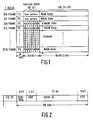
- Figs. 1 and 2 represent the format of a standard CD signal,
- Figs. 3 and 4 show possible forms of the alternating pattern of the logic values of the "copy" bits for a record carrier in accordance with the invention,
- Fig. 5 shows an information recording device in accordance with the invention,
- Fig. 6 shows in detail a circuit for use in the information recording device shown in Fig. 5,
- Fig. 7 shows an information copying system employing information recording devices in accordance with the invention,
- Fig. 8 shows in detail a detection circuit for use in the information recording devices shown in Fig. 7, and
- Fig. 9 is a flow chart of a program for determining whether recording of the received information is allowed.
- Fig. 1 illustrates the data format of a digital signal in conformity with the CD standard. Such a signal is divided into blocks (Block) of 98 FRAMES each. Each FRAME comprises data bits (DB) representing the main information (MAIN DATA) and subcode information (subcode DATA). The subcode information of
FRAME 2 throughFRAME 97 comprises eight subcode bits for each FRAME. The subcode bits within a block constitute subcode frames of the P-W-subcode channels, each subcode frame comprising 96 subcode bits. - Fig. 2 illustrates the format of the subcode frame of the subcode Q channel. This subcode frame comprises a 4-bit "control" group, including one bit referred to as the "copy" bit. The logic value of the "copy bit" indicates whether the associated main information may be copied freely. For the well known Compact Disc the logic value of the "copy" bit is the same throughout the disc, which means that in every subcode frame on the Compact Disc the copy bit either has the logic value "1" or the logic value "0".
- In the case of a record carrier in accordance with the invention the logic values of the "copy" bits alternate, for example as illustrated in Fig. 3 and Fig. 4, in order to indicate that the recorded information is a copy.
- In the case of the alternation pattern shown in Fig. 3 the values of the copy bits alternate periodically, 4 subcode frames each comprising a "copy" bit of the logic value "0" each time alternating with 4 subcode frames each comprising a "copy" bit of the logic value "1".
- In Fig. 4 the logic values of the copy bits also vary periodically, but here 6 subcode frames comprising copy bits of the logic value "0" each time alternate with 2 subcode frames comprising copy bits of the logic value "1". Recording different alternation patterns of different forms, as illustrated in Figs. 3 and 4, also provides the possibility of indicating on the record carrier whether the copy is a first-generation copy or a second or higher-generation copy.
- In the alternation patterns illustrated in Figs. 3 and 4 the duty cycle differs, which is the ratio between the number of "copy" bits of the logic value "0" in a period and the total number of bits in each period of the alternation pattern.
- It will be evident to those skilled in the art that the alternation patterns can also specify the generation number of a copy in a copying cycle in a different manner, for example by periodic alternation patterns of different period lengths.
- By means of a suitable d.c. free coding of the logic values of the "copy" bits it is also possible to transmit information about the generation number and, if desired, other information via the "copy" bit.
- Transmitting information via an alternating logic value of the "copy" bit has the advantage that this remains within the scope of the CD standard. This means that the information can be read by means of a standard CD player.
- Fig. 5 shows an embodiment of a recording device for obtaining a record carrier on which the logic values of the "copy" bits alternate. The recording device comprises a cascade arrangement of a
CIRC encoder 50 and anEFM modulator 51 for converting the applied digital information, originating from for example analog-to-digital converters, into a format prescribed by the CD standard. TheEFM modulator 51 supplies an output signal of this format to acontrol circuit 52 for anoptical write head 53 arranged opposite a rotatingoptical record carrier 54 of an inscribable type. The recording device further comprises a clocksignal generation circuit 55 for generating clock signals for controlling theCIRC encoder 50 and theEFM modulator 51. The EFM modulator further comprises inputs for applying subcode information to theEFM modulator 51. The logic value of the "copy" bit to be recorded is supplied to theEFM modulator 51 by acircuit 57via asignal line 56. Thecircuit 57 supplies a periodic signal to the EFM modulator. This periodic signal can be derived, for example by frequency division, from a clock signal which is applied to thecircuit 57 by the clocksignal generation circuit 55via asignal line 58. - Fig. 6 shows another embodiment of the
circuit 57 enabling an alternation pattern of a specific form to be selected from a plurality of alternation patterns of different forms. For this purpose thecircuit 56 comprises acircuit 60 which derives a plurality of signals having alternation patterns of different forms, for example alternation patterns having different "duty cycles", from the clock signal appliedvia thesignal line 58. These signals are applied to aselection circuit 61 which transfers one of the applied signals to thesignal line 56 depending on a control signal Vs. - Since alternating logic values of the "copy" bits on the record carrier in accordance with the invention indicate that the recorded information is a copy further copying can be inhibited simply by detecting whether the logic values of the copy bits in the information applied for recording alternate and inhibiting recording if "copy" bits of alternating logic values are detected.
- Fig. 7 shows an embodiment of an information copying system in which this is realized. This information copying system comprises an
optical read device 70 for reading optical discs, amagnetic recording device 71, and anoptical recording device 72 for recording information read by theread device 70. - The
read device 70 is of a customary type adapted to read CD information from anoptical record carrier 73. For this purpose theread device 70 comprises an optical read head which is coupled to a cascade arrangement of a customaryCIRC decoding circuit 75 and anEFM demodulator 76, which for example form part of an integrated circuit of the type SAA 7210 marketed by PHILIPS. Such anEFM demodualtor 76 produces tw digitised stereo audio information signals and a subcode signal on its outputs. These signals are applied to aformatting circuit 77, for example of the type SAA 7220, which converts the received information into a format prescribed by a digital audio interface standard (IEC 950). This digital audio interface format comprises blocks of 192 main information frames, and a plurality of interface subcode frames. These subcode frames each comprise an interface "copy" bit whose logic value, in accordance with the digital audio interface standard, is taken over from the "copy" bit in the subcode information of the information being read. - An output signal complying with the digital audio interface standard is applied to reformatting
circuits 78 of the readdevices - The reformatting
circuits 78 convert the received information into a format suitable for processing by therecording devices - The reformatting circuits may be constituted, for example, by an integrated circuit of the type SX 23053 marketed by SONY. This type of reformatting circuit produces the main information and the subcode information on its outputs. The circuit further comprises an output to which "copy"-bit information CB relating to the logic value of the received interface "copy" bit is applied and an output to which a block synchronisation signal BS is applied to indicate the beginning of each digital audio interface block received.
- In the
magnetic recording device 71 the information supplied by the reformattingcircuit 78 is applied to acircuit 79 of a customary type for driving a magnetic-head system 80 for recording the received information on aDAT cassette tape 81. Similarly, the information supplied by the reformattingcircuit 78 in the optical read device is applied to acircuit 82 of a customary type, which comprises for example an EFM modulator and CIRC encoder, to drive anoptical write head 83 for recording the received information on anoptical record carrier 84. In therecording devices circuit 78 are applied to adetection circuit 85 for detecting whether the logic value of the received "copy"-bit information alternates. - The
detector circuit 85 supplies a detection signal Vd if the alternating logic value of the "copy"-bit information is detected. - Fig. 8 shows an example of a
detection circuit 85 comprising three clocked D flip-flops flops flop 90. The output of the flip-flop 90 is connected to the data input of the flip-flop 91 and to an input of an Exclusive-OR gate 93. Another input of the Exclusive-OR gate 93 is connected to the output of the flip-flop 97 The output of the Exclusive-OR gate 93 is connected to the data input of the flip-flop 92. The output signal on the output of the flip-flop 93 serves as the detection signal Vd. The circuit shown in Fig. 8 operates as follows. If the logic value of the interface "copy" bit changes the logic value of the signal on the input of the flip-flop 91 at the instant at which the first "copy" bit of changed logic value reaches the input of the flip-flop 91 will no longer correspond to the logic value of the signal on the output of the flip-flop 91. In that case the logic value of the output of the Exclusive-OR gate becomes a logic "1" value. This value is latched in the flip-flop 92, after which the detection signal Vd also assumes the logic "1" value. - In the
recording device 71 the detection signal Vd is applied to adecision circuit 94. Moreover, the subcode information supplied by the reformattingcircuit 78 is applied to thedecision circuit 94. On the basis of the received subcode information and the detection signal Vd thedecision circuit 94 decides whether recording of the received main information is allowed. If recording is not allowed the decision circuit generates a control signal which is applied to thecontrol circuit 79via thesignal line 95, thecontrol circuit 79 being of a type which is disabled in response to the control signal appliedvia the signal line, so that recording of information is inhibited. Thedecision circuit 94 may comprise, for example, a microcomputer loaded with a suitable program. However, before this program is described in detail that part of the received subcode information of the digital audio interface format will be described which is important for a correct understanding of the decision criteria. In particular the subcode C-channel of the digital audio interface format of the received subcode information is of interest. This subcode C-channel comprises subcode frames of 192 bits. These subcode frames indicate whether the information stems from a source intended for professional use. Moreover, it is indicated whether the associated information stems from an audio source. Moreover, for sources intended for consumer applications the subcode C-channel contains a category code indicating the type of source. This may be for example a 2-channel Compact Disc audio system, a 2-channel digital audio type player, etc. - Fig. 9 is a flow chart of a decision program for determining whether recording of the received information is allowed. This decision program is based on the decision program employed in the "Solocopy" system. However, the program has been adapted to make the decision dependent upon the detection of alternating logic values of the "copy" bits.
- In step S1 of the program it is ascertained by means of the information from the subcode C-channel whether the information originates from an information source intended for professional uses. If this is the case, recording is inhibited in step S2. In step S3 it is checked whether the received information is audio information. If this is not the case, recording is inhibited in step S4. In step S5 it is checked whether the received category code occurs in the list of known category codes. If this is not the case, recording is enabled in step S6 and, in addition, information is recorded on the
tape 81 to indicate that the recorded information is a copy. If the information is read subsequently a category code is assigned to the information to denote that recording is not allowed. However, the manner in which this is effected falls beyond the scope of the present invention and is therefore not described in detail. - In step S7 it is checked whether the information stems from an analog-to-digital converter. If this is the case, recording is enabled in step S8. In step S9 it is determined on the basis of the received detection signal Vd whether the logic values of the received interface copy bits alternate. If the values alternate, recording is inhibited in step S10. In step S11 it is ascertained on the basis of the received logic values of the copy bits whether the relevant information may be copied freely. If this is the case, recording is enabled in step S12, information being added to indicate that the recorded information may be copied freely.
- In step S13 it is checked whether the category code specifies a source for which copying of the supplied information is allowed. If this is the case recording is enabled in step S14. If it is not the case, recording is inhibited in step S15.
- The
recording device 72 comprises adecision circuit 98 which is largely identical to thedecision circuit 94. However, in the case that information is recorded which should not be copied any more, thedecision circuit 98 generates a control signal for acircuit 96 which causes "copy" bits of alternating logic values to be recorded. - For the
circuit 96 thecircuits 57 described above may be employed. - It is also possible to provide the
circuit 72 with adetection circuit 97 for detecting the generation number in a copy cycle for the received information on the basis of the form of the alternation pattern. The decision whether the received information may be recorded or not can then be taken on the basis of the detected generation number of the information. For example, copying of a first-generation copy may be allowed while copying of a second generation copy is not allowed. - The
circuit 98 should be adapted in such a manner that depending on the detected generation number it generates an alternation pattern indicating a higher generation number than the detected generation number. - In the foregoing the invention has been illustrated for a record carrier carrying a standard CD signal having "copy" bits with alternating logic values to indicate that the recorded information is a copy. However, it is to benoted that, in principle, the invention may be applied to any record carrier which in addition to the main information carries subcode information comprising a "copy" bit.
Claims (19)
- A record carrier carrying main information together with a series of subcode frames which each comprise a "copy" bit, characterized in that the logic values of the "copy" bits of consecutive subcode frames alternate.
- A record carrier as claimed in Claim 1, characterized in that the form of the pattern indicates the generation number of the information in a copying cycle.
- A record carrier as claimed in Claim 2, characterized in that the detected pattern is a periodic pattern in which the ratio between the number of "copy" bits of a first logic value in a period and the total number of "copy" bits in said period indicates the generation number.
- A record carrier as claimed in Claim 1, 2 or 3, characterized in that the recorded information is a standard CD signal.
- A method of obtaining a record carrier as claimed in Claim 1, 2, 3 or 4, main information together with a series of subcode frames which each comprise a "copy" bit being recorded on the record carrier, characterized in that during recording logic values are assigned to the "copy" bits of consecutive subcode frames in accordance with an alternation pattern.
- A method as claimed in Claim 5, characterized in that the information to be copied is previously recorded information, the form of the alternation pattern being dependent upon the generation number of the previously recorded information.
- A method as claimed in Claim 6, characterized in that the detected pattern is a periodic pattern, the ratio between the number of "copy" bits of a first logic value in a period the and total number of "copy" bits in said period being selected depending upon the generation number.
- A method as claimed in Claim 5, 6 or 7, characterized in that the information being recorded is a standard CD signal.
- An information recording device for obtaining a record carrier as claimed in Claim 1, 2, 3 or 4, which device is constructed to record on the record carrier main information together with a series of subcode frames which each comprise a "copy" bit, characterized in that the device comprises assignment means for assigning the logic values in accordance with an alternation pattern to the "copy" bits of consecutive subcode frames of information to be recorded.
- An information recording device as claimed in Claim 9, characterized in that the assignment means comprise selection means for selecting an alternation pattern of a specific form from a plurality of patterns of predetermined forms depending upon a control signal.
- An information recording device as claimed in Claim 10, characterized in that the selection means are adapted to select a periodic pattern whose ratio between the number of "copy" bits of a first logic value in a period and the total number of "copy" bits in said period depends upon the control signal.
- An information recording device as claimed in Claim 9, 10 or 11, characterized in that the device is adapted to record standard CD signals.
- An information recording device comprising anti-copy means for inhibiting unauthorized copying of received information, for recording main information, which is received together with a series of subcode frames which each comprise a "copy" bit, which anti-copy means comprise decision means for deciding whether recording of received information is allowed depending upon the logic value of the received "copy" bits and means responsive to a decision that recording is not allowed to inhibit recording, characterized in that the device comprises detection means for detecting an alternation pattern in the logic values of the received "copy" bits of consecutive subcode frames, the decision means being adapted to decide whether recording is allowed depending upon the detection of the alternation pattern.
- An information recording device as claimed in Claim 13, characterized in that the detection means are adapted to detect alternation patterns of different forms, the decision means being adapted to decide whether recording is allowed depending upon the form of the detected alternation pattern.
- An information recording device as claimed in Claim 14, characterized in that the detection means are adapted to detect in a period of a periodically alternating pattern the ratio between the number of "copy" bits of a first logic value and the total number of "copy" bits in said period, the decision means being adapted to decide whether recording is permitted depending upon the detected ratio.
- An information recording device as claimed in Claim 13, 14 or 15, for recording main information together with a series of second subcode frames, which each comprise a second copy bit, characterized in that the device comprises assignment means for assigning the logic values to the second "copy" bits of consecutive second subcode frames in accordance with an alternation pattern.
- An information recording device as claimed in Claims 14 and 16, characterized in that the assignment means are adapted to assign the logic value to the second copy bit in accordance with a pattern whose form depends on the form of the detected alternation pattern in the logic values of the "copy" bits in the subcode frames of the received information.
- An information recording device as claimed in Claims 15 and 17, characterized in that the assignment means are adapted to assign the logic values to the second copy bits in accordance with a periodic pattern, the ratio between second "copy" bits of a first logic value in a period and the total number of second copy bits in said period being dependent upon the detected ratio.
- An information recording device as claimed in any one of the Claims 13 to 18, characterized in that the device is adapted to receive information formatted in accordance with a standard audio interface format.
Applications Claiming Priority (2)
| Application Number | Priority Date | Filing Date | Title |
|---|---|---|---|
| NL8902358 | 1989-09-21 | ||
| NL8902358 | 1989-09-21 |
Publications (2)
| Publication Number | Publication Date |
|---|---|
| EP0418964A1 EP0418964A1 (en) | 1991-03-27 |
| EP0418964B1true EP0418964B1 (en) | 1995-02-08 |
Family
ID=19855337
Family Applications (1)
| Application Number | Title | Priority Date | Filing Date |
|---|---|---|---|
| EP90202448AExpired - LifetimeEP0418964B1 (en) | 1989-09-21 | 1990-09-17 | Record carrier, method of and information recording device for obtaining such record carriers, and information recording device comprising anti-copy means to inhibit unauthorized copying |
Country Status (20)
| Country | Link |
|---|---|
| US (2) | US5428598A (en) |
| EP (1) | EP0418964B1 (en) |
| JP (3) | JP3273781B2 (en) |
| KR (1) | KR100231670B1 (en) |
| CN (1) | CN1030629C (en) |
| AR (1) | AR247311A1 (en) |
| AT (1) | ATE118288T1 (en) |
| AU (1) | AU657465B2 (en) |
| BR (1) | BR9004656A (en) |
| CA (1) | CA2025644C (en) |
| CZ (1) | CZ285659B6 (en) |
| DE (1) | DE69016725T2 (en) |
| DK (1) | DK0418964T3 (en) |
| ES (1) | ES2070267T3 (en) |
| HK (1) | HK75696A (en) |
| HU (1) | HU212224B (en) |
| MY (1) | MY106622A (en) |
| RU (1) | RU1836721C (en) |
| SK (1) | SK280686B6 (en) |
| UA (1) | UA29373C2 (en) |
Cited By (9)
| Publication number | Priority date | Publication date | Assignee | Title |
|---|---|---|---|---|
| US6754377B2 (en) | 1995-05-08 | 2004-06-22 | Digimarc Corporation | Methods and systems for marking printed documents |
| US6975746B2 (en) | 1993-11-18 | 2005-12-13 | Digimarc Corporation | Integrating digital watermarks in multimedia content |
| US6993153B2 (en) | 2000-02-10 | 2006-01-31 | Digimarc Corporation | Self-orienting watermarks |
| US7027614B2 (en) | 2000-04-19 | 2006-04-11 | Digimarc Corporation | Hiding information to reduce or offset perceptible artifacts |
| US7171016B1 (en) | 1993-11-18 | 2007-01-30 | Digimarc Corporation | Method for monitoring internet dissemination of image, video and/or audio files |
| US7362879B2 (en) | 1999-12-28 | 2008-04-22 | Digimarc Corporation | Substituting objects based on steganographic encoding |
| US7486799B2 (en) | 1995-05-08 | 2009-02-03 | Digimarc Corporation | Methods for monitoring audio and images on the internet |
| US7756290B2 (en) | 2000-01-13 | 2010-07-13 | Digimarc Corporation | Detecting embedded signals in media content using coincidence metrics |
| US8204222B2 (en) | 1993-11-18 | 2012-06-19 | Digimarc Corporation | Steganographic encoding and decoding of auxiliary codes in media signals |
Families Citing this family (99)
| Publication number | Priority date | Publication date | Assignee | Title |
|---|---|---|---|---|
| JP3128328B2 (en)* | 1992-05-26 | 2001-01-29 | キヤノン株式会社 | Recording device |
| JP3217137B2 (en)* | 1992-07-28 | 2001-10-09 | 株式会社日立製作所 | Video signal recording device, playback device, and transmission device |
| US5721788A (en) | 1992-07-31 | 1998-02-24 | Corbis Corporation | Method and system for digital image signatures |
| US6301369B2 (en) | 1992-07-31 | 2001-10-09 | Digimarc Corporation | Image marking to permit later identification |
| US5315448A (en)* | 1993-03-18 | 1994-05-24 | Macrovision Corporation | Copy protection for hybrid digital video tape recording and unprotected source material |
| JP3674872B2 (en)* | 1993-06-16 | 2005-07-27 | パイオニア株式会社 | Audio signal recording apparatus and audio signal recording method |
| TW241360B (en)* | 1993-07-29 | 1995-02-21 | Nippon Pickter Kk | |
| EP0640924A3 (en)* | 1993-08-17 | 1997-04-23 | Sony Corp | Data reproducing apparatus. |
| JP2945569B2 (en)* | 1993-10-27 | 1999-09-06 | シャープ株式会社 | Information recording and playback method |
| US6681029B1 (en)* | 1993-11-18 | 2004-01-20 | Digimarc Corporation | Decoding steganographic messages embedded in media signals |
| US5768426A (en) | 1993-11-18 | 1998-06-16 | Digimarc Corporation | Graphics processing system employing embedded code signals |
| US6516079B1 (en) | 2000-02-14 | 2003-02-04 | Digimarc Corporation | Digital watermark screening and detecting strategies |
| US7313251B2 (en) | 1993-11-18 | 2007-12-25 | Digimarc Corporation | Method and system for managing and controlling electronic media |
| US6757406B2 (en) | 1993-11-18 | 2004-06-29 | Digimarc Corporation | Steganographic image processing |
| US6983051B1 (en) | 1993-11-18 | 2006-01-03 | Digimarc Corporation | Methods for audio watermarking and decoding |
| US5748763A (en) | 1993-11-18 | 1998-05-05 | Digimarc Corporation | Image steganography system featuring perceptually adaptive and globally scalable signal embedding |
| US6122403A (en) | 1995-07-27 | 2000-09-19 | Digimarc Corporation | Computer system linked by using information in data objects |
| JP3321972B2 (en)* | 1994-02-15 | 2002-09-09 | ソニー株式会社 | Digital signal recording device |
| AU693147B2 (en)* | 1994-02-28 | 1998-06-25 | Sony Corporation | Method and device for recording data, data recording medium,and method and device for reproducing data |
| US7286684B2 (en)* | 1994-03-17 | 2007-10-23 | Digimarc Corporation | Secure document design carrying auxiliary machine readable information |
| US6522770B1 (en) | 1999-05-19 | 2003-02-18 | Digimarc Corporation | Management of documents and other objects using optical devices |
| US5715355A (en) | 1994-03-19 | 1998-02-03 | Sony Corporation | Optical disk having a particular format to store user-selected data, such as video data or computer files, including a dedicated TOC region |
| US5610893A (en)* | 1994-06-02 | 1997-03-11 | Olympus Optical Co., Ltd. | Information recording and reproducing apparatus for copying information from exchangeable master recording medium to a plurality of other exchangeable recording media |
| US5530751A (en)* | 1994-06-30 | 1996-06-25 | Hewlett-Packard Company | Embedded hidden identification codes in digital objects |
| JPH0845246A (en)* | 1994-07-29 | 1996-02-16 | Sony Corp | Recording medium, reproducing method, recording device and reproducing device |
| CN1084107C (en)* | 1994-08-31 | 2002-05-01 | 索尼公司 | still image system |
| JP3469650B2 (en)* | 1994-09-13 | 2003-11-25 | ソニー株式会社 | Optical recording medium and signal recording method |
| US6560349B1 (en) | 1994-10-21 | 2003-05-06 | Digimarc Corporation | Audio monitoring using steganographic information |
| JP2915307B2 (en)* | 1994-12-19 | 1999-07-05 | 株式会社日立製作所 | Information recording control method for optical disk |
| MY125739A (en)* | 1994-12-22 | 2006-08-30 | Sony Corp | Recording medium and apparatus for protecting copyrighted digital data |
| US6490113B2 (en) | 1994-12-22 | 2002-12-03 | Sony Corporation | Recording medium and apparatus for protecting copyrighted digital data |
| US5644444A (en)* | 1995-03-10 | 1997-07-01 | Iomega Corporation | Read/write protect scheme for a disk cartridge and drive |
| US6724554B1 (en) | 1995-03-10 | 2004-04-20 | Iomega Corporation | Read/write protect scheme for a disk cartridge and drive |
| US7555139B2 (en)* | 1995-05-08 | 2009-06-30 | Digimarc Corporation | Secure documents with hidden signals, and related methods and systems |
| MY112755A (en)* | 1995-06-06 | 2001-08-30 | Sony Corp | Information data reproducing system, reproducing apparatus, reproducing method, data forming apparatus and data record medium |
| DE19525425C1 (en)* | 1995-07-12 | 1996-10-24 | Siemens Ag | Video signal reception system with recording prevention |
| JP3252706B2 (en)* | 1995-07-21 | 2002-02-04 | ソニー株式会社 | Video signal reproduction method and apparatus, and signal transmission method and apparatus |
| US7065211B1 (en) | 1995-07-21 | 2006-06-20 | Sony Corporation | Signal reproducing/recording/transmitting method and apparatus and signal recording medium |
| US6411725B1 (en)* | 1995-07-27 | 2002-06-25 | Digimarc Corporation | Watermark enabled video objects |
| US6965682B1 (en) | 1999-05-19 | 2005-11-15 | Digimarc Corp | Data transmission by watermark proxy |
| KR100460158B1 (en)* | 1995-08-10 | 2005-04-06 | 소니 가부시끼 가이샤 | Data transfer method, data recording device, data recording medium and data reproducing device |
| JP3467964B2 (en)* | 1995-08-10 | 2003-11-17 | ソニー株式会社 | Data recording device and method, data reproducing device and method, recording medium, and data transmission method |
| JP4518574B2 (en)* | 1995-08-11 | 2010-08-04 | ソニー株式会社 | Recording method and apparatus, recording medium, and reproducing method and apparatus |
| US6687828B1 (en)* | 1995-08-11 | 2004-02-03 | Sony Corporation | Method and apparatus for ciphering playback mode information for recording on record medium |
| US6345145B1 (en)* | 1995-08-25 | 2002-02-05 | Sony Corporation | Signal recording/reproducing method and apparatus, signal record medium and signal transmission/reception method and apparatus |
| US5703859A (en) | 1995-09-01 | 1997-12-30 | Sony Corporation | Digital video copy protection system |
| JP3484838B2 (en)* | 1995-09-22 | 2004-01-06 | ソニー株式会社 | Recording method and playback device |
| US5719937A (en)* | 1995-12-06 | 1998-02-17 | Solana Technology Develpment Corporation | Multi-media copy management system |
| JP3371659B2 (en)* | 1995-12-28 | 2003-01-27 | ソニー株式会社 | Recording device and control method |
| US5901178A (en)* | 1996-02-26 | 1999-05-04 | Solana Technology Development Corporation | Post-compression hidden data transport for video |
| JPH09231665A (en)* | 1996-02-28 | 1997-09-05 | Sony Corp | Recording system and recording/reproducing system |
| JPH09245438A (en)* | 1996-03-12 | 1997-09-19 | Pioneer Electron Corp | Information recording medium and recording equipment and reproducing equipment therefor |
| US6381341B1 (en) | 1996-05-16 | 2002-04-30 | Digimarc Corporation | Watermark encoding method exploiting biases inherent in original signal |
| US6209096B1 (en) | 1996-07-02 | 2001-03-27 | Yamaha Corporation | Method and device for storing main information with associated additional information incorporated therein |
| US5960398A (en)* | 1996-07-31 | 1999-09-28 | Wictor Company Of Japan, Ltd. | Copyright information embedding apparatus |
| US6011772A (en) | 1996-09-16 | 2000-01-04 | Spectradisc Corporation | Machine-readable optical disc with reading-inhibit agent |
| KR100215705B1 (en)* | 1996-11-02 | 1999-08-16 | 구자홍 | Method for recording information without damaging before hand recorded information |
| US5787068A (en)* | 1996-11-07 | 1998-07-28 | Imation Corp. | Method and arrangement for preventing unauthorized duplication of optical discs using barriers |
| WO1998029869A1 (en)* | 1996-12-17 | 1998-07-09 | Leske Lawrence A | Access to information using protectable authorization messages |
| US6747930B1 (en) | 1996-12-24 | 2004-06-08 | Hide & Seek Technologies, Inc. | Data protection on an optical disk |
| CN101154421A (en)* | 1997-05-29 | 2008-04-02 | 索尼公司 | Record reproduction device and record reproduction method |
| JPH1145556A (en)* | 1997-05-29 | 1999-02-16 | Sony Corp | Device and method for recording audio data |
| JP3588536B2 (en)* | 1997-07-11 | 2004-11-10 | 株式会社東芝 | Unauthorized data copy prevention apparatus and method |
| US6345028B1 (en) | 1997-11-03 | 2002-02-05 | Intertactile Technologies Corporation | Method for direct recording and playback of multiple data tracks and signals |
| US6278807B1 (en)* | 1997-11-13 | 2001-08-21 | Kabushiki Kaisha Toshiba | Data recording/reproducing apparatus, data recording/reproducing method applied to the apparatus, and computer program product used in data processing apparatus |
| US6804376B2 (en) | 1998-01-20 | 2004-10-12 | Digimarc Corporation | Equipment employing watermark-based authentication function |
| WO1999041738A1 (en)* | 1998-02-11 | 1999-08-19 | Mazer Terrence B | Limited use optical playback device |
| JP2000048478A (en)* | 1998-05-26 | 2000-02-18 | Yamaha Corp | Digital copy control method, and device using the method |
| US6338933B1 (en) | 1998-06-25 | 2002-01-15 | Spectradisc Corporation | Methods and apparatus for rendering an optically encoded medium unreadable |
| US6531262B1 (en) | 1998-06-25 | 2003-03-11 | Spectradisc Corporation | Methods and apparatus for rendering an optically encoded medium unreadable and tamper-resistant |
| JP3951464B2 (en)* | 1998-07-28 | 2007-08-01 | 株式会社日立製作所 | Digital signal processor |
| DE69935124T2 (en)* | 1998-10-05 | 2007-11-22 | Koninklijke Philips Electronics N.V. | SYSTEM FOR COPY PROTECTION OF RECORDED INFORMATION |
| US6748079B1 (en)* | 1998-10-14 | 2004-06-08 | Macrovision Corporation | Method and system for recording data on and reading data from an optical medium |
| JP2002532812A (en)* | 1998-12-18 | 2002-10-02 | ディジマーク コーポレイション | Anti-counterfeiting system |
| WO2000068945A1 (en)* | 1999-05-11 | 2000-11-16 | Macrovision Corporation | Secure compact disk and player |
| JP4003348B2 (en)* | 1999-05-28 | 2007-11-07 | ソニー株式会社 | Recording / playback device |
| JP4243059B2 (en)* | 1999-07-12 | 2009-03-25 | フレックスプレイ・テクノロジーズ・インコーポレイテッド | Single-use optical storage medium and manufacturing method thereof |
| JP2001118331A (en) | 1999-10-19 | 2001-04-27 | Sony Corp | Recorder, recording and reproducing device and recording method |
| US7356142B1 (en) | 2000-05-10 | 2008-04-08 | Macrovision Corporation | Secure compact disk and player |
| US6842522B1 (en) | 2000-06-01 | 2005-01-11 | Macrovision Corporation | Secure digital video disk and player |
| US6928040B2 (en)* | 2000-06-14 | 2005-08-09 | Macrovision Corporation | Identifying copy protected optical compact discs |
| JP4784036B2 (en)* | 2000-06-27 | 2011-09-28 | ソニー株式会社 | Data recording method, data recording apparatus, and recording medium |
| US20050063256A1 (en)* | 2000-06-30 | 2005-03-24 | Selinfreund Richard H. | Data storage in optical discs |
| US7124944B2 (en) | 2000-06-30 | 2006-10-24 | Verification Technologies, Inc. | Product packaging including digital data |
| AU2001259033A1 (en) | 2000-06-30 | 2002-01-14 | Verification Technologies, Inc. | Copy-protected optical media and method of manufacture thereof |
| US6638593B2 (en) | 2000-06-30 | 2003-10-28 | Verification Technologies, Inc. | Copy-protected optical media and method of manufacture thereof |
| US7486790B1 (en) | 2000-06-30 | 2009-02-03 | Verification Technologies, Inc. | Method and apparatus for controlling access to storage media |
| US7660415B2 (en) | 2000-08-03 | 2010-02-09 | Selinfreund Richard H | Method and apparatus for controlling access to storage media |
| US6982109B2 (en)* | 2000-12-11 | 2006-01-03 | Flexplay Technologies, Inc. | Method for rendering surface layer of limited play disk lightfast |
| JP2004532492A (en)* | 2001-03-19 | 2004-10-21 | サンコム、インク. | Digital content hiding apparatus and method |
| AU2002305849B2 (en)* | 2001-06-05 | 2008-01-17 | Flexplay Technologies, Inc. | Limited play optical devices with interstitial reactive layer and methods of making same |
| US20030088773A1 (en)* | 2001-11-07 | 2003-05-08 | Koninklijke Philips Electronics N. V. | Method of and apparatus for preventing illicit copying of digital content |
| US7302575B2 (en)* | 2001-11-07 | 2007-11-27 | Koninklijke Philips Electronics N.V. | Apparatus for and method of preventing illicit copying of digital content |
| US7219062B2 (en)* | 2002-01-30 | 2007-05-15 | Koninklijke Philips Electronics N.V. | Speech activity detection using acoustic and facial characteristics in an automatic speech recognition system |
| JP3985596B2 (en)* | 2002-06-19 | 2007-10-03 | ソニー株式会社 | Information detection apparatus, recording apparatus, and information detection method |
| US8181884B2 (en)* | 2003-11-17 | 2012-05-22 | Digimarc Corporation | Machine-readable features for objects |
| US8752198B2 (en) | 2005-05-26 | 2014-06-10 | Hewlett-Packard Development Company, L.P. | Virtual write protection system |
| US20080092153A1 (en)* | 2006-10-11 | 2008-04-17 | Imation Corp. | System and process for forming a durable image on an optical disk |
| DE102013208530A1 (en)* | 2013-05-08 | 2014-11-13 | Robert Bosch Gmbh | memory device |
Family Cites Families (9)
| Publication number | Priority date | Publication date | Assignee | Title |
|---|---|---|---|---|
| CA1183950A (en)* | 1980-09-26 | 1985-03-12 | Bo Lofberg | Method for processing an information signal and means for carrying out the method |
| JPH0787021B2 (en)* | 1983-10-14 | 1995-09-20 | ヤマハ株式会社 | Subcode signal reading circuit |
| US4849836A (en)* | 1985-06-07 | 1989-07-18 | Software Heaven, Inc. | Copy protection for computer discs |
| JPH0743825B2 (en)* | 1985-12-04 | 1995-05-15 | ソニー株式会社 | Dubbing method |
| US4849386A (en) | 1987-04-08 | 1989-07-18 | Taiwan Styrene Monomer Corporation | Novel silicon-modified catalyst Si/HZSM-5 preparation |
| US4775401A (en)* | 1987-06-18 | 1988-10-04 | American Telephone And Telegraph Company, At&T Bell Laboratories | Method of producing an optical fiber |
| EP0297539B1 (en)* | 1987-06-30 | 1993-09-01 | Kabushiki Kaisha Toshiba | Recording control apparatus |
| US5057947A (en)* | 1988-02-10 | 1991-10-15 | Matsushita Electric Industrial Co., Ltd. | Recording and reproducing apparatus with limited digital copying |
| US5231546A (en)* | 1988-02-10 | 1993-07-27 | Matsushita Electric Industrial Co., Ltd. | Recording and reproducing apparatus with limited digital copying |
- 1990
- 1990-09-14ARAR90317873Apatent/AR247311A1/enactive
- 1990-09-14JPJP24596690Apatent/JP3273781B2/ennot_activeExpired - Lifetime
- 1990-09-17ATAT90202448Tpatent/ATE118288T1/ennot_activeIP Right Cessation
- 1990-09-17DKDK90202448.8Tpatent/DK0418964T3/enactive
- 1990-09-17EPEP90202448Apatent/EP0418964B1/ennot_activeExpired - Lifetime
- 1990-09-17ESES90202448Tpatent/ES2070267T3/ennot_activeExpired - Lifetime
- 1990-09-17DEDE69016725Tpatent/DE69016725T2/ennot_activeExpired - Lifetime
- 1990-09-18CACA002025644Apatent/CA2025644C/ennot_activeExpired - Lifetime
- 1990-09-18KRKR1019900014719Apatent/KR100231670B1/ennot_activeExpired - Lifetime
- 1990-09-18UAUA4831698Apatent/UA29373C2/enunknown
- 1990-09-18HUHU905949Apatent/HU212224B/enunknown
- 1990-09-18CZCS904536Apatent/CZ285659B6/ennot_activeIP Right Cessation
- 1990-09-18CNCN90107903Apatent/CN1030629C/ennot_activeExpired - Lifetime
- 1990-09-18MYMYPI90001610Apatent/MY106622A/enunknown
- 1990-09-18RUSU904831698Apatent/RU1836721C/enactive
- 1990-09-18BRBR909004656Apatent/BR9004656A/ennot_activeIP Right Cessation
- 1990-09-18SKSK4536-90Apatent/SK280686B6/ennot_activeIP Right Cessation
- 1990-09-19AUAU62666/90Apatent/AU657465B2/ennot_activeExpired
- 1993
- 1993-09-01USUS08/115,340patent/US5428598A/ennot_activeExpired - Lifetime
- 1994
- 1994-08-16USUS08/291,328patent/US5453968A/ennot_activeExpired - Lifetime
- 1996
- 1996-05-02HKHK75696Apatent/HK75696A/ennot_activeIP Right Cessation
- 2001
- 2001-10-03JPJP2001307968Apatent/JP3648190B2/ennot_activeExpired - Lifetime
- 2004
- 2004-12-09JPJP2004356542Apatent/JP2005166253A/enactivePending
Cited By (12)
| Publication number | Priority date | Publication date | Assignee | Title |
|---|---|---|---|---|
| US6975746B2 (en) | 1993-11-18 | 2005-12-13 | Digimarc Corporation | Integrating digital watermarks in multimedia content |
| US7171016B1 (en) | 1993-11-18 | 2007-01-30 | Digimarc Corporation | Method for monitoring internet dissemination of image, video and/or audio files |
| US7308110B2 (en) | 1993-11-18 | 2007-12-11 | Digimarc Corporation | Methods for marking images |
| US8204222B2 (en) | 1993-11-18 | 2012-06-19 | Digimarc Corporation | Steganographic encoding and decoding of auxiliary codes in media signals |
| US6754377B2 (en) | 1995-05-08 | 2004-06-22 | Digimarc Corporation | Methods and systems for marking printed documents |
| US6922480B2 (en) | 1995-05-08 | 2005-07-26 | Digimarc Corporation | Methods for encoding security documents |
| US7486799B2 (en) | 1995-05-08 | 2009-02-03 | Digimarc Corporation | Methods for monitoring audio and images on the internet |
| US7362879B2 (en) | 1999-12-28 | 2008-04-22 | Digimarc Corporation | Substituting objects based on steganographic encoding |
| US7756290B2 (en) | 2000-01-13 | 2010-07-13 | Digimarc Corporation | Detecting embedded signals in media content using coincidence metrics |
| US8027510B2 (en) | 2000-01-13 | 2011-09-27 | Digimarc Corporation | Encoding and decoding media signals |
| US6993153B2 (en) | 2000-02-10 | 2006-01-31 | Digimarc Corporation | Self-orienting watermarks |
| US7027614B2 (en) | 2000-04-19 | 2006-04-11 | Digimarc Corporation | Hiding information to reduce or offset perceptible artifacts |
Also Published As
| Publication number | Publication date |
|---|---|
| JP3648190B2 (en) | 2005-05-18 |
| DE69016725T2 (en) | 1995-09-07 |
| US5453968A (en) | 1995-09-26 |
| ATE118288T1 (en) | 1995-02-15 |
| CA2025644C (en) | 2000-02-08 |
| KR100231670B1 (en) | 1999-11-15 |
| CZ453690A3 (en) | 1999-07-14 |
| JP2002208224A (en) | 2002-07-26 |
| UA29373C2 (en) | 2000-11-15 |
| JP3273781B2 (en) | 2002-04-15 |
| CA2025644A1 (en) | 1991-03-22 |
| MY106622A (en) | 1995-06-30 |
| HU212224B (en) | 1996-04-29 |
| AU657465B2 (en) | 1995-03-16 |
| US5428598A (en) | 1995-06-27 |
| ES2070267T3 (en) | 1995-06-01 |
| JP2005166253A (en) | 2005-06-23 |
| DE69016725D1 (en) | 1995-03-23 |
| JPH03108162A (en) | 1991-05-08 |
| BR9004656A (en) | 1991-09-10 |
| SK453690A3 (en) | 2000-06-12 |
| CN1030629C (en) | 1996-01-03 |
| EP0418964A1 (en) | 1991-03-27 |
| CN1050457A (en) | 1991-04-03 |
| HK75696A (en) | 1996-05-10 |
| AR247311A1 (en) | 1994-11-30 |
| SK280686B6 (en) | 2000-06-12 |
| RU1836721C (en) | 1993-08-23 |
| DK0418964T3 (en) | 1995-07-10 |
| AU6266690A (en) | 1991-04-11 |
| KR910006957A (en) | 1991-04-30 |
| CZ285659B6 (en) | 1999-10-13 |
| HUT54822A (en) | 1991-03-28 |
Similar Documents
| Publication | Publication Date | Title |
|---|---|---|
| EP0418964B1 (en) | Record carrier, method of and information recording device for obtaining such record carriers, and information recording device comprising anti-copy means to inhibit unauthorized copying | |
| AU634709B2 (en) | Recording system as well as record carrier and recording apparatus for use in the system | |
| KR0130207B1 (en) | Digital recorder | |
| US7284128B2 (en) | Recording medium, recording medium method and apparatus , information signal output control method, recording medium reproducing apparatus, signal transmission method, and content data | |
| US20020027990A1 (en) | Signal transmision method | |
| EP1486970A1 (en) | Copy protection of optical media | |
| JPS60246184A (en) | Identification circuit of magnetic disc | |
| EP0286437B1 (en) | Apparatus and method for recording and reproducing a digital signal | |
| JPS62107473A (en) | Sub-code information taking-in method at the time of recording of pcm tape recorder | |
| EP1596388A1 (en) | Data recording method and device, data recording medium, data reproduction method and device, data transmission method and device, and data reception method and device | |
| JPH04147485A (en) | Digital audio signal recorder | |
| US20030172285A1 (en) | Method and apparatus for ciphering playback mode information for recording on record medium | |
| JPH05266586A (en) | Digital audio recording/reproducing system | |
| JPH0991869A (en) | Digital signal recording device | |
| KR930010914B1 (en) | Sub-coding circuit of recording and reproducing system | |
| US20060098541A1 (en) | Recorder, recording method, reproducer, reproducing method, and recording medium | |
| JPS5930279A (en) | Control signal generating device | |
| JP2005523546A (en) | Copy detection and protection method using time jump | |
| JP2002197651A (en) | Optical disk, and device and method for preparing optical disk original | |
| JPS6018862A (en) | Information recording and reproducing device |
Legal Events
| Date | Code | Title | Description |
|---|---|---|---|
| PUAI | Public reference made under article 153(3) epc to a published international application that has entered the european phase | Free format text:ORIGINAL CODE: 0009012 | |
| AK | Designated contracting states | Kind code of ref document:A1 Designated state(s):AT BE CH DE DK ES FR GB GR IT LI LU NL SE | |
| 17P | Request for examination filed | Effective date:19910924 | |
| 17Q | First examination report despatched | Effective date:19940329 | |
| GRAA | (expected) grant | Free format text:ORIGINAL CODE: 0009210 | |
| AK | Designated contracting states | Kind code of ref document:B1 Designated state(s):AT BE CH DE DK ES FR GB GR IT LI LU NL SE | |
| REF | Corresponds to: | Ref document number:118288 Country of ref document:AT Date of ref document:19950215 Kind code of ref document:T | |
| REF | Corresponds to: | Ref document number:69016725 Country of ref document:DE Date of ref document:19950323 | |
| ITF | It: translation for a ep patent filed | ||
| ET | Fr: translation filed | ||
| REG | Reference to a national code | Ref country code:ES Ref legal event code:FG2A Ref document number:2070267 Country of ref document:ES Kind code of ref document:T3 | |
| REG | Reference to a national code | Ref country code:DK Ref legal event code:T3 | |
| REG | Reference to a national code | Ref country code:GR Ref legal event code:FG4A Free format text:3016025 | |
| PLBE | No opposition filed within time limit | Free format text:ORIGINAL CODE: 0009261 | |
| STAA | Information on the status of an ep patent application or granted ep patent | Free format text:STATUS: NO OPPOSITION FILED WITHIN TIME LIMIT | |
| 26N | No opposition filed | ||
| REG | Reference to a national code | Ref country code:CH Ref legal event code:PFA Free format text:PHILIPS ELECTRONICS N.V. TRANSFER- KONINKLIJKE PHILIPS ELECTRONICS N.V. | |
| NLT1 | Nl: modifications of names registered in virtue of documents presented to the patent office pursuant to art. 16 a, paragraph 1 | Owner name:KONINKLIJKE PHILIPS ELECTRONICS N.V. | |
| REG | Reference to a national code | Ref country code:FR Ref legal event code:CD | |
| REG | Reference to a national code | Ref country code:ES Ref legal event code:PC2A | |
| REG | Reference to a national code | Ref country code:GB Ref legal event code:IF02 | |
| PGFP | Annual fee paid to national office [announced via postgrant information from national office to epo] | Ref country code:DK Payment date:20090930 Year of fee payment:20 | |
| PGFP | Annual fee paid to national office [announced via postgrant information from national office to epo] | Ref country code:AT Payment date:20090925 Year of fee payment:20 Ref country code:LU Payment date:20090929 Year of fee payment:20 Ref country code:GB Payment date:20090930 Year of fee payment:20 Ref country code:CH Payment date:20090929 Year of fee payment:20 Ref country code:NL Payment date:20090924 Year of fee payment:20 | |
| PGFP | Annual fee paid to national office [announced via postgrant information from national office to epo] | Ref country code:DE Payment date:20091127 Year of fee payment:20 Ref country code:ES Payment date:20091021 Year of fee payment:20 Ref country code:SE Payment date:20090925 Year of fee payment:20 | |
| PGFP | Annual fee paid to national office [announced via postgrant information from national office to epo] | Ref country code:IT Payment date:20090929 Year of fee payment:20 Ref country code:FR Payment date:20091016 Year of fee payment:20 | |
| PGFP | Annual fee paid to national office [announced via postgrant information from national office to epo] | Ref country code:GR Payment date:20090924 Year of fee payment:20 | |
| PGFP | Annual fee paid to national office [announced via postgrant information from national office to epo] | Ref country code:BE Payment date:20091117 Year of fee payment:20 | |
| REG | Reference to a national code | Ref country code:NL Ref legal event code:V4 Effective date:20100917 | |
| BE20 | Be: patent expired | Owner name:*KONINKLIJKE PHILIPS ELECTRONICS N.V. Effective date:20100917 | |
| REG | Reference to a national code | Ref country code:CH Ref legal event code:PL | |
| REG | Reference to a national code | Ref country code:DK Ref legal event code:EUP | |
| REG | Reference to a national code | Ref country code:GB Ref legal event code:PE20 Expiry date:20100916 | |
| EUG | Se: european patent has lapsed | ||
| PG25 | Lapsed in a contracting state [announced via postgrant information from national office to epo] | Ref country code:GB Free format text:LAPSE BECAUSE OF EXPIRATION OF PROTECTION Effective date:20100916 | |
| PG25 | Lapsed in a contracting state [announced via postgrant information from national office to epo] | Ref country code:NL Free format text:LAPSE BECAUSE OF EXPIRATION OF PROTECTION Effective date:20100917 | |
| REG | Reference to a national code | Ref country code:ES Ref legal event code:FD2A Effective date:20120110 | |
| PG25 | Lapsed in a contracting state [announced via postgrant information from national office to epo] | Ref country code:ES Free format text:LAPSE BECAUSE OF EXPIRATION OF PROTECTION Effective date:20100918 | |
| PG25 | Lapsed in a contracting state [announced via postgrant information from national office to epo] | Ref country code:DE Free format text:LAPSE BECAUSE OF EXPIRATION OF PROTECTION Effective date:20100917 |