EP0418047B1 - Glass window antenna for motor vehicle - Google Patents
Glass window antenna for motor vehicleDownload PDFInfo
- Publication number
- EP0418047B1 EP0418047B1EP90309966AEP90309966AEP0418047B1EP 0418047 B1EP0418047 B1EP 0418047B1EP 90309966 AEP90309966 AEP 90309966AEP 90309966 AEP90309966 AEP 90309966AEP 0418047 B1EP0418047 B1EP 0418047B1
- Authority
- EP
- European Patent Office
- Prior art keywords
- antenna
- glass
- conductor
- heater wires
- reception
- Prior art date
- Legal status (The legal status is an assumption and is not a legal conclusion. Google has not performed a legal analysis and makes no representation as to the accuracy of the status listed.)
- Expired - Lifetime
Links
- 239000011521glassSubstances0.000titleclaimsdescription53
- 239000004020conductorSubstances0.000claimsdescription60
- 239000005357flat glassSubstances0.000claimsdescription8
- 239000005340laminated glassSubstances0.000claimsdescription6
- 230000008878couplingEffects0.000claimsdescription5
- 238000010168coupling processMethods0.000claimsdescription5
- 238000005859coupling reactionMethods0.000claimsdescription5
- 239000011229interlayerSubstances0.000description3
- 239000010410layerSubstances0.000description3
- RYGMFSIKBFXOCR-UHFFFAOYSA-NCopperChemical compound[Cu]RYGMFSIKBFXOCR-UHFFFAOYSA-N0.000description2
- 229910052802copperInorganic materials0.000description2
- 239000010949copperSubstances0.000description2
- BQCADISMDOOEFD-UHFFFAOYSA-NSilverChemical compound[Ag]BQCADISMDOOEFD-UHFFFAOYSA-N0.000description1
- 230000015556catabolic processEffects0.000description1
- 238000006731degradation reactionMethods0.000description1
- 230000000873masking effectEffects0.000description1
- 239000002184metalSubstances0.000description1
- 229910052751metalInorganic materials0.000description1
- 229920005989resinPolymers0.000description1
- 239000011347resinSubstances0.000description1
- 229910052709silverInorganic materials0.000description1
- 239000004332silverSubstances0.000description1
- 229910000679solderInorganic materials0.000description1
- 229920003002synthetic resinPolymers0.000description1
- 239000000057synthetic resinSubstances0.000description1
Images


Classifications
- H—ELECTRICITY
- H01—ELECTRIC ELEMENTS
- H01Q—ANTENNAS, i.e. RADIO AERIALS
- H01Q1/00—Details of, or arrangements associated with, antennas
- H01Q1/12—Supports; Mounting means
- H01Q1/1271—Supports; Mounting means for mounting on windscreens
Definitions
- This inventionrelates to a glass antenna for a motor vehicle, more particularly, to a glass window antenna which applies reception power to a receiver in a diversity reception system.
- Reception conditionsvary in accordance with movement of reception point when an FM or TV broadcast wave is received by a traveling motor vehicle.
- a space diversity reception system using a plurality of antenna elementsis employed to prevent the quality of a radio voice or a TV picture from being degraded by the variation of the reception field. It is known to constitute these antenna elements for diversity reception with glass window antennas formed of conductors printed on a window glass of the motor vehicle (refer to, for example, Japanese patent application laid-open No. 203702/1986).
- Document EP-A-0 297 328discloses several antennas assigned to several reception bands on a single vehicle window where the heater conductors are also used as antenna conductors.
- JP-A-01 57802discloses an antenna conductor in the non-defogging area which is inserted as an intermediate layer in a laminated window.
- a glass window antennais usually arranged on a rear glass window for convenience to keep the field of view of the front windshield clear as well as ameliorating the problem of wiring between the antenna and a receiver.
- the space available in which to arrange the antenna conductoris however limited to the upper or lower blank portion outside the middle area where defogging heater wires are attached by printing. It is not possible to provide many antenna conductors on a glass window having small blank areas. In particular, a small-sized automobile has an upright rear window with less blank area to arrange necessary antenna conductors thereon. Moreover, when many antenna conductors are arranged in the blank portion, they must have simple configuration with few constitutuent elements. It restricts tuning factors of reception directivity and bandwidth.
- a window glass antenna for a motor vehiclecomprises a group of heater wires provided in a defogging area on the inside surface of a laminated window glass consisting of an inner glass and an outer glass; a first antenna conductor arranged out of said defogging area on the inside surface of the inner glass; a second antenna conductor inserted into an intermediate layer of the laminated glass and extending to cross the heater wires; and a coupling member to couple said first and second antenna conductors for constituting a single synthesized antenna; the first antenna conductor being assigned to a lower reception band and said second antenna conductor being assigned to an upper reception band.
- the first antenna conductorshows sufficient gain with a relatively simple conductor pattern since it is limited to reception of lower reception band, though conductors are hard to pattern into a complex form for tuning on a narrow blank area.
- the second antenna conductoris insulated from the heater wires by glass so that the conductor can be a vertical element crossing the heater wires. A vertical element mounted on a motor vehicle can be easily tuned in higher frequency band.
- the synthesized antennaconsisting of the first and second antenna conductors coupled with each other has good reception characteristics over a wide frequency range.
- An antenna system which effectively uses a narrow space on the window glassis obtained.
- Fig. 1is a front view of a rear window glass showing an embodiment of glass window antenna of a motor vehicle according to this invention.
- the rear glass window 1is formed of a laminated glass consisting of an inner glass 2 and an outer glass 3 which are put together with an interlayer 4 formed of a transparent synthetic resin film intervening therebetween.
- a lot of heater wires 5are arranged in a defogging area located in the central portion of the rear glass window 1.
- the heater wires 5are supplied with power to remove fog on the glass surface from bus bars 6 and 7 at one end of the heater wires 5 which are connected by a bus bar 8 at their other end.
- These bus bars 6, 7 and 8 and the heater wires 5are formed on the inner glass 2 by printing silver paste or the like on the inner surface thereof and baking thereafter, as shown in Fig. 2 illustrating a front view of the inner glass.
- Antenna conductorsare arranged on the same surface on which the heater wires are attached, that is, inside the inner glass 2, in upper and lower blank areas outside the defogging area.
- the antenna conductorsare formed by printing conductive paste.
- a main antenna 10is arranged to receive AM/FM broadcast waves.
- the main antenna 10comprises horizontal elements 10a and 10b extending horizontally from a feed terminal 11 located at left side portion of the glass and then folded to turn at right side portion, a horizontal element 10c connected through a connecting element 10d to a tuning point located at a position displaced from the center of the element 10a, a horizontal element 10e shaped into letter-L and extending from the feed terminal 11 closely alongside the element 10c, and a horizontal element 10g connected to the center of the element 10b through a connecting element 10f.
- a horizontal element 5ais arranged parallel and close to the element 10g.
- the center of the element 5ais connected to the center of the uppermost heater wire 5 through a connecting element 5b so that induced broadcast frequencies (mainly AM frequencies) on the heater wires 5 are transferred to the AM/FM main antenna 10.
- An FM subantenna 12consisting of two parallel horizontal element 12a and 12b about 400 mm and 200 mm long is provided on the left side of the lower blank area. Reception power induced on the subantenna 12 is derived from an FM feed terminal 13 located below the bus bar 13.
- Reception outputs at the feed terminals 11 and 13 of the main antenna 10 and subantenna 12are fed to an FM diversity receiver through feeder cables 26 and 27.
- AM reception output of the main antenna 10is fed to an AM receiver from the feed terminal 11 through cable 26.
- the diversity receiveris adapted to receive TV broadcast frequency.
- First to fourth TV feed terminals 14 -17are provided inside the inner glass 2 to feed TV reception power.
- a masking 9is provided along the edges of the window glass 1 with a width sufficient for concealing the bus bars 6, 7 and 8 and the feed terminals 11, 13 14 - 17 from the outside of the motor vehicle.
- the first TV feed terminal 14is provided on the bus bar 8 to feed TV reception signal induced on the heater wires 5.
- An auxiliary element 5cis extended from an end portion of the uppermost heater wire 5 to compensate for the reception characteristics of the heater wires 5, which are utilized as the first TV antenna.
- a second TV antenna 20is coupled to a second feed terminal 15 which is located below the bus bar 8.
- the second TV antenna 20comprises a horizontal element 20a printed inside the inner glass, and a horizontal element 20c connected by an element 20b to the second feed terminal 15 to extend closely parallel with the lowermost heater wires 5.
- These elements 20a and 20care respectively 500 mm and 200 mm in length and are tuned in lower band of TV broadcast wave.
- the second TV antenna 20further comprises a wire antenna element 20d arranged to cross the heater wires 5 so as to have a vertical component.
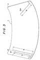
- the wire antenna element 20dis formed of a metal wire having a diameter of about 0.13 mm which is provided inside the outer glass 3 so as to be put between the outer glass 3 and the interlayer 4, as shown in Fig. 3 illustrating a front view of the outer glass 3.
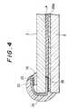
- the wire antenna element 20dis therefore insulated from the heater wires 5 with the inner glass 2 and the interlayer 4 as shown in a cross-sectional view of Fig. 4.
- the wire antenna element 20dis about 300 mm in length and has a vertical component which effectively receives a higher band of TV broadcast frequencies. As there is less capacitive coupling between the wire antenna element 20d and the heater wires 5, the wire antenna has less degradation of its reception characteristic in the higher band.
- the wire antenna element 20d in the intermediate layeris coupled to the feed terminal 15 arranged inside the inner glass 2 through a copper thin plate 23 fixed by solder 25.
- a wide-band synthesized reception signalconsisting of a low band component and a high band component is obtained at the feed terminal 15 respectively from the horizontal elements 20a and 20c and the wire antenna element 20d.
- the coupling portion by the copper thin plate 23is covered with a resin seal 24.
- the lower end of the wire antenna element 21 and the upper end of the wire antenna element 22are respectively extended to a side edge of the outer glass 2 and then connected to the third and fourth feed terminals 16 and 17 located inside the inner glass 2 through the same connecting arrangement as that shown in Fig. 4.
- the TV reception signals obtained at the first to fourth feed terminals 14 - 17are supplied to a TV tuner of the diversity reception system.
- the wire antenna elements 20d, 21 and 22may be formed of printed conductors.
- the first antenna conductor 20a and 20c arranged in the blank area outside the area of the heater wires 5is restricted to exclusive use in a lower reception band so that it can be tuned to have a high gain even in a narrow space on the glass.
- a sufficient reception gainis obtained over a wide range with a synthesized output generated by the first antenna conductor and the second antenna conductor 20d which is tuned for exclusive use in the higher band.
- the second antenna conductor 20dcan be a vertical element crossing the heater wires 5 so that it can be easily tuned for use in the higher band.
- the second antenna conductor 20dshows a good reception characteristic in a high frequency range as it has less capacitive coupling with the heater wires.
- Diversity receptionis performed with signals consisting of the reception outputs of antenna conductors 21 and 22, the reception output of the heater wires 5 and the reception output of the synthesized antenna. Good reception characteristics are obtained by using several antenna elements even in a case where areas for the antenna conductors on a window glass is restricted.
Landscapes
- Details Of Aerials (AREA)
Description
- This invention relates to a glass antenna for a motor vehicle, more particularly, to a glass window antenna which applies reception power to a receiver in a diversity reception system.
- Reception conditions vary in accordance with movement of reception point when an FM or TV broadcast wave is received by a traveling motor vehicle. A space diversity reception system using a plurality of antenna elements is employed to prevent the quality of a radio voice or a TV picture from being degraded by the variation of the reception field. It is known to constitute these antenna elements for diversity reception with glass window antennas formed of conductors printed on a window glass of the motor vehicle (refer to, for example, Japanese patent application laid-open No. 203702/1986).
- Document EP-A-0 297 328 discloses several antennas assigned to several reception bands on a single vehicle window where the heater conductors are also used as antenna conductors.
- Document PATENT ABSTRACTS OF JAPAN, vol. 13, no. 268 (E-775)(3616) 20 June 1989 & JP-A-01 57802 discloses an antenna conductor in the non-defogging area which is inserted as an intermediate layer in a laminated window.
- Document EP-A-0 346 591, published after the priority date of the present application, and relevant according to Articles 52 and 54 (3) EPC, discloses an antenna with two antenna conductors situated respectively outside and inside the defogging area. The second conductor extends to cross the heater wires. However, the two conductors are not assigned to two differing reception bands, and are situated on a same surface of the laminated window.
- A glass window antenna is usually arranged on a rear glass window for convenience to keep the field of view of the front windshield clear as well as ameliorating the problem of wiring between the antenna and a receiver.
- The space available in which to arrange the antenna conductor is however limited to the upper or lower blank portion outside the middle area where defogging heater wires are attached by printing. It is not possible to provide many antenna conductors on a glass window having small blank areas. In particular, a small-sized automobile has an upright rear window with less blank area to arrange necessary antenna conductors thereon. Moreover, when many antenna conductors are arranged in the blank portion, they must have simple configuration with few constitutuent elements. It restricts tuning factors of reception directivity and bandwidth.
- Accordingly, it is an object of this invention to arrange antenna conductors having high efficiency for diversity reception on a limited area of glass window.
- It is another object of this invention to provide arrangements of antenna conductors which can be incorporated with a space and frequency diversity reception system.
- A window glass antenna for a motor vehicle according to this invention comprises a group of heater wires provided in a defogging area on the inside surface of a laminated window glass consisting of an inner glass and an outer glass; a first antenna conductor arranged out of said defogging area on the inside surface of the inner glass; a second antenna conductor inserted into an intermediate layer of the laminated glass and extending to cross the heater wires; and a coupling member to couple said first and second antenna conductors for constituting a single synthesized antenna; the first antenna conductor being assigned to a lower reception band and said second antenna conductor being assigned to an upper reception band.
- The first antenna conductor shows sufficient gain with a relatively simple conductor pattern since it is limited to reception of lower reception band, though conductors are hard to pattern into a complex form for tuning on a narrow blank area. The second antenna conductor is insulated from the heater wires by glass so that the conductor can be a vertical element crossing the heater wires. A vertical element mounted on a motor vehicle can be easily tuned in higher frequency band.
- The synthesized antenna consisting of the first and second antenna conductors coupled with each other has good reception characteristics over a wide frequency range. An antenna system which effectively uses a narrow space on the window glass is obtained.
- The above, and other, objects, features and advantages of the present invention, will become readily apparent from the following detailed description thereof which is to be read in connection with the accompanying drawings.
- Fig. 1 is a front view of a rear glass window showing one embodiment according to this invention;
- Fig. 2 is a front view of an inner glass having conductors arranged inside thereof;
- Fig. 3 is a front view of an outer glass showing wire antennas arranged inside thereof; and
- Fig. 4 is a cross-sectional view showing connecting feature of a feeding portion.
- Fig. 1 is a front view of a rear window glass showing an embodiment of glass window antenna of a motor vehicle according to this invention. The rear glass window 1 is formed of a laminated glass consisting of an
inner glass 2 and anouter glass 3 which are put together with an interlayer 4 formed of a transparent synthetic resin film intervening therebetween. - A lot of
heater wires 5 are arranged in a defogging area located in the central portion of the rear glass window 1. Theheater wires 5 are supplied with power to remove fog on the glass surface frombus bars heater wires 5 which are connected by abus bar 8 at their other end. Thesebus bars heater wires 5 are formed on theinner glass 2 by printing silver paste or the like on the inner surface thereof and baking thereafter, as shown in Fig. 2 illustrating a front view of the inner glass. - Antenna conductors are arranged on the same surface on which the heater wires are attached, that is, inside the
inner glass 2, in upper and lower blank areas outside the defogging area. The antenna conductors are formed by printing conductive paste. On the relatively large upper blank area, amain antenna 10 is arranged to receive AM/FM broadcast waves. - The
main antenna 10 compriseshorizontal elements feed terminal 11 located at left side portion of the glass and then folded to turn at right side portion, ahorizontal element 10c connected through a connectingelement 10d to a tuning point located at a position displaced from the center of theelement 10a, ahorizontal element 10e shaped into letter-L and extending from thefeed terminal 11 closely alongside theelement 10c, and ahorizontal element 10g connected to the center of theelement 10b through a connectingelement 10f. Ahorizontal element 5a is arranged parallel and close to theelement 10g. The center of theelement 5a is connected to the center of theuppermost heater wire 5 through a connectingelement 5b so that induced broadcast frequencies (mainly AM frequencies) on theheater wires 5 are transferred to the AM/FMmain antenna 10. - An
FM subantenna 12 consisting of two parallelhorizontal element subantenna 12 is derived from anFM feed terminal 13 located below thebus bar 13. - Reception outputs at the
feed terminals main antenna 10 andsubantenna 12 are fed to an FM diversity receiver throughfeeder cables main antenna 10 is fed to an AM receiver from thefeed terminal 11 throughcable 26. - The diversity receiver is adapted to receive TV broadcast frequency. First to fourth TV feed terminals 14 -17 are provided inside the
inner glass 2 to feed TV reception power. A masking 9 is provided along the edges of the window glass 1 with a width sufficient for concealing thebus bars feed terminals - The first
TV feed terminal 14 is provided on thebus bar 8 to feed TV reception signal induced on theheater wires 5. Anauxiliary element 5c is extended from an end portion of theuppermost heater wire 5 to compensate for the reception characteristics of theheater wires 5, which are utilized as the first TV antenna. - A
second TV antenna 20 is coupled to asecond feed terminal 15 which is located below thebus bar 8. Thesecond TV antenna 20 comprises ahorizontal element 20a printed inside the inner glass, and ahorizontal element 20c connected by anelement 20b to thesecond feed terminal 15 to extend closely parallel with thelowermost heater wires 5. Theseelements - The
second TV antenna 20 further comprises awire antenna element 20d arranged to cross theheater wires 5 so as to have a vertical component. Thewire antenna element 20d is formed of a metal wire having a diameter of about 0.13 mm which is provided inside theouter glass 3 so as to be put between theouter glass 3 and the interlayer 4, as shown in Fig. 3 illustrating a front view of theouter glass 3. Thewire antenna element 20d is therefore insulated from theheater wires 5 with theinner glass 2 and the interlayer 4 as shown in a cross-sectional view of Fig. 4. Thewire antenna element 20d is about 300 mm in length and has a vertical component which effectively receives a higher band of TV broadcast frequencies. As there is less capacitive coupling between thewire antenna element 20d and theheater wires 5, the wire antenna has less degradation of its reception characteristic in the higher band. - As shown in the cross-sectional view of Fig. 4, the
wire antenna element 20d in the intermediate layer is coupled to thefeed terminal 15 arranged inside theinner glass 2 through a copperthin plate 23 fixed bysolder 25. A wide-band synthesized reception signal consisting of a low band component and a high band component is obtained at thefeed terminal 15 respectively from thehorizontal elements wire antenna element 20d. The coupling portion by the copperthin plate 23 is covered with aresin seal 24. - Two long and short
wire antenna elements outer glass 3 to extend vertically along left side thereof. The longwire antenna element 21 is utilized as a third TV antenna which has a length l₂=600 mm and is tuned in a lower band (1-3 channels) of VHF-TV broadcast frequencies. - The short
wire antenna element 22 is utilized as a fourth TV antenna which has a length l₃=400 mm and is tuned in a higher band (4-12 channels) of VHF-TV broadcast frequencies. - The lower end of the
wire antenna element 21 and the upper end of thewire antenna element 22 are respectively extended to a side edge of theouter glass 2 and then connected to the third andfourth feed terminals inner glass 2 through the same connecting arrangement as that shown in Fig. 4. - The TV reception signals obtained at the first to fourth feed terminals 14 - 17 are supplied to a TV tuner of the diversity reception system.
- In the above-mentioned embodiment, the
wire antenna elements - According to the invention, the
first antenna conductor heater wires 5 is restricted to exclusive use in a lower reception band so that it can be tuned to have a high gain even in a narrow space on the glass. A sufficient reception gain is obtained over a wide range with a synthesized output generated by the first antenna conductor and thesecond antenna conductor 20d which is tuned for exclusive use in the higher band. Thesecond antenna conductor 20d can be a vertical element crossing theheater wires 5 so that it can be easily tuned for use in the higher band. In particular, thesecond antenna conductor 20d shows a good reception characteristic in a high frequency range as it has less capacitive coupling with the heater wires. - Diversity reception is performed with signals consisting of the reception outputs of
antenna conductors heater wires 5 and the reception output of the synthesized antenna. Good reception characteristics are obtained by using several antenna elements even in a case where areas for the antenna conductors on a window glass is restricted.
Claims (10)
- A glass window antenna for a motor vehicle having a group of heater wires provided in a defogging area on the inside surface of a laminated window glass consisting of an inner glass and an outer glass, characterized by comprising:
a first antenna conductor (20a, 20b, 20c) arranged out of said defogging area on the inside surface of the inner glass (2);
a second antenna conductor (20d) inserted into an intermediate layer (4) of the laminated glass (2, 3) and extending to cross the heater wires (5); and
a coupling member (23) to couple said first and second antenna conductors for constituting a single synthesized antenna (20),
said first antenna conductor being assigned to a lower reception band and said second antenna conductor being assigned to an upper reception band. - A glass window antenna according to claim 1, characterized in that a feed terminal (15) of said synthesized antenna (20) is formed on the inside surface of said inner glass (2).
- A glass window antenna according to claim 2, characterized in that said first antenna conductor comprises a single horizontal conductor (20a) extending from said feed terminal (15) and a horizontal conductor (20c) extending closely alongside the heater wires (5) to collect induced reception power from said heater wires.
- A glass window antenna according to claim 1, characterized by further comprising a third antenna conductor (21) inserted into the intermediate layer (4) of the laminated glass (2, 3) and extending to cross the heater wires (5) in a lateral side area different from the area where said synthesized antenna (20) is arranged,
an output of said third antenna conductor being derived for diversity reception together with the output of said synthesized antenna. - A glass window antenna according to claim 4, characterized in that said third antenna conductor comprises two independent antenna conductors (21, 22) consisting of a long, single line conductor (21) and a short, single line conductor (22) respectively connected to different feed terminals (16, 17).
- A glass window antenna according to claim 5, characterized in that said feed terminals (16, 17) of said third antenna conductor (21, 22) are located respectively on the inside surface of upper and lower portions of said inner glass (2),
said long and short line conductors (21, 22) extending in opposite direction to each other to cross said heater wires (5) and said line conductors being respectively connected to the corresponding feed terminals (16, 17) through connecting members (23). - A glass window antenna according to claim 4, characterized by further comprising a fourth antenna conductor employing said heater wires (5), reception outputs by said synthesized antenna (20), said third antenna conductor (21, 22) and said fourth antenna conductor (5, 5c) being derived to a diversity reception system.
- A glass window antenna according to claim 7, characterized in that said fourth antenna conductor comprises said heater wires (5) and an auxiliary, horizontal antenna conductor (5c) formed on the inside surface of the inner glass and connected to said heater wires to extend from the side area of the laminated glass where said synthesized antenna (20) is located.
- A glass window antenna according to claim 5, characterized in that said first and second antenna conductors (20a, 20b, 20c) are assigned respectively to a lower band and an upper band of a TV broadcast band and said short and long line conductors (21, 22) are assigned respectively to a upper band and a lower band of the TV broadcast band.
- A glass window antenna according to claim 9, characterized by further comprising an antenna conductor (10) provided outside the defogging area on the inside surface of the inner glass (2) of the laminated glass for reception of a radio broadcast wave.
Applications Claiming Priority (2)
| Application Number | Priority Date | Filing Date | Title |
|---|---|---|---|
| JP1238576AJPH03101402A (en) | 1989-09-14 | 1989-09-14 | Glass antenna for automobile |
| JP238576/89 | 1989-09-14 |
Publications (3)
| Publication Number | Publication Date |
|---|---|
| EP0418047A2 EP0418047A2 (en) | 1991-03-20 |
| EP0418047A3 EP0418047A3 (en) | 1991-07-31 |
| EP0418047B1true EP0418047B1 (en) | 1994-12-21 |
Family
ID=17032267
Family Applications (1)
| Application Number | Title | Priority Date | Filing Date |
|---|---|---|---|
| EP90309966AExpired - LifetimeEP0418047B1 (en) | 1989-09-14 | 1990-09-12 | Glass window antenna for motor vehicle |
Country Status (4)
| Country | Link |
|---|---|
| US (1) | US5119106A (en) |
| EP (1) | EP0418047B1 (en) |
| JP (1) | JPH03101402A (en) |
| DE (1) | DE69015292T2 (en) |
Cited By (1)
| Publication number | Priority date | Publication date | Assignee | Title |
|---|---|---|---|---|
| US8530792B2 (en) | 2003-08-20 | 2013-09-10 | Agc Automotive Americas Co. | Heated side window glass |
Families Citing this family (27)
| Publication number | Priority date | Publication date | Assignee | Title |
|---|---|---|---|---|
| JP2636440B2 (en)* | 1989-10-31 | 1997-07-30 | セントラル硝子株式会社 | Glass antenna for vehicles |
| JPH04249407A (en)* | 1991-02-05 | 1992-09-04 | Harada Ind Co Ltd | Automobile glass antenna |
| JP2538136B2 (en)* | 1991-04-30 | 1996-09-25 | セントラル硝子株式会社 | Glass antenna for vehicles |
| DE69313165T2 (en)* | 1992-03-06 | 1997-12-18 | Central Glass Co Ltd | Window antenna for motor vehicles |
| JPH06177625A (en)* | 1992-10-06 | 1994-06-24 | Central Glass Co Ltd | Automotive glass antenna |
| US5644321A (en)* | 1993-01-12 | 1997-07-01 | Benham; Glynda O. | Multi-element antenna with tapered resistive loading in each element |
| DE4302139C1 (en)* | 1993-01-27 | 1994-03-31 | Flachglas Ag | Connector for electrical element in laminated glass - comprises metal strip with fold lines for bending around inner glass sheet edge |
| JP3458975B2 (en)* | 1993-12-28 | 2003-10-20 | マツダ株式会社 | Glass antenna for vehicle and setting method thereof |
| US5640167A (en)* | 1995-01-27 | 1997-06-17 | Ford Motor Company | Vehicle window glass antenna arrangement |
| CA2211698A1 (en)* | 1995-02-06 | 1996-08-15 | Megawave Corporation | Window glass antenna |
| JPH10513328A (en)* | 1995-02-06 | 1998-12-15 | メガウエイブ コーポレーション | TV antenna |
| US5610619A (en)* | 1995-11-20 | 1997-03-11 | Delco Electronics Corporation | Backlite antenna for AM/FM automobile radio having broadband FM reception |
| US5790079A (en)* | 1995-11-22 | 1998-08-04 | Delco Electronics Corporation | Backlite antenna for AM/FM automobile radio |
| GB2309829B (en)* | 1996-01-23 | 2000-02-16 | Wipac Group Limited | Vehicle on-screen antenna |
| JP3460217B2 (en)* | 1996-06-20 | 2003-10-27 | マツダ株式会社 | Glass antenna for vehicle and setting method thereof |
| GB2316538A (en)* | 1996-08-21 | 1998-02-25 | Antiference Ltd | Vehicle windscreen antenna and heater element arrangement |
| US5959587A (en)* | 1997-09-12 | 1999-09-28 | Ppg Industries Ohio, Inc. | On the glass antenna system |
| TW508865B (en)* | 2000-06-22 | 2002-11-01 | Asahi Glass Co Ltd | Glass antenna for an automobile |
| JP3555863B2 (en)* | 2000-07-06 | 2004-08-18 | Nec液晶テクノロジー株式会社 | Reflector, method of manufacturing the same, and liquid crystal display device using the same |
| US6730848B1 (en)* | 2001-06-29 | 2004-05-04 | Antaya Technologies Corporation | Techniques for connecting a lead to a conductor |
| KR20050013333A (en)* | 2003-07-28 | 2005-02-04 | 현대자동차주식회사 | Radio receiver for a vehicle and method thereof |
| ES2694780T3 (en) | 2010-05-19 | 2018-12-27 | Saint-Gobain Glass France | Antenna optimized in the bandwidth by hybrid structure of planar and linear radiator |
| CN103098541B (en)* | 2010-09-14 | 2015-06-17 | Lg化学株式会社 | Heating element and method of manufacturing the same |
| CN109417222B (en)* | 2016-07-01 | 2021-09-21 | 日本板硝子株式会社 | Window glass for vehicle |
| KR101699209B1 (en)* | 2016-10-06 | 2017-01-24 | 하태경 | Meat roasting grill pan |
| IT201800002486A1 (en)* | 2018-02-08 | 2019-08-08 | Gd Spa | Automatic product processing machine and corresponding control method |
| US12311637B2 (en) | 2022-11-04 | 2025-05-27 | Agc Automotive Americas Co. | Laminated glazing assembly including an antenna assembly |
Family Cites Families (17)
| Publication number | Priority date | Publication date | Assignee | Title |
|---|---|---|---|---|
| US3484583A (en)* | 1968-07-23 | 1969-12-16 | Ppg Industries Inc | Combination of electrically heated transparent window and antenna |
| IT951602B (en)* | 1970-12-08 | 1973-07-10 | Saint Gobain | PROCEDURE FOR THE IMPROVEMENT OF THE RECEPTION CONDITIONS OF ANTENNA GLASSES FOR VEHICLES AND IMPROVED RECEPTION ANTENNA GLASSES |
| FR2250329A5 (en)* | 1973-10-31 | 1975-05-30 | Saint Gobain | |
| JPS5870643A (en)* | 1981-10-22 | 1983-04-27 | Toyota Motor Corp | Receiver for car |
| US4608570A (en)* | 1982-11-18 | 1986-08-26 | Central Glass Company, Limited | Automotive window glass antenna |
| JPS61203702A (en)* | 1985-03-07 | 1986-09-09 | Asahi Glass Co Ltd | Antenna system for automobile |
| JPS6130102A (en)* | 1984-07-20 | 1986-02-12 | Nippon Sheet Glass Co Ltd | Antenna of window glass for automobile |
| JPS6173403A (en)* | 1984-09-19 | 1986-04-15 | Nissan Motor Co Ltd | automotive glass antenna |
| JPS61175010A (en)* | 1985-01-31 | 1986-08-06 | Hino Motors Ltd | Molding method |
| JPH0640769B2 (en)* | 1986-02-18 | 1994-06-01 | 株式会社スズテック | Strip seeding equipment for nursery boxes |
| GB2193846B (en)* | 1986-07-04 | 1990-04-18 | Central Glass Co Ltd | Vehicle window glass antenna using transparent conductive film |
| JP2685745B2 (en)* | 1986-09-03 | 1997-12-03 | 株式会社東芝 | Color picture tube |
| JP2513196B2 (en)* | 1986-11-25 | 1996-07-03 | ソニー株式会社 | Differential amplifier circuit |
| GB2200498B (en)* | 1986-12-19 | 1990-07-18 | Central Glass Co Ltd | Vehicle window glass antenna using transparent conductive film |
| JP2563927B2 (en)* | 1987-04-27 | 1996-12-18 | マツダ株式会社 | Car antenna device |
| DE3719692A1 (en)* | 1987-06-12 | 1988-12-22 | Flachenecker Gerhard | MULTI-ANTENNA ARRANGEMENT FOR ANTENNA DIVERSITY IN A WINDOW WINDOW |
| DE3820229C1 (en)* | 1988-06-14 | 1989-11-30 | Heinz Prof. Dr.-Ing. 8033 Planegg De Lindenmeier |
- 1989
- 1989-09-14JPJP1238576Apatent/JPH03101402A/enactivePending
- 1990
- 1990-09-12EPEP90309966Apatent/EP0418047B1/ennot_activeExpired - Lifetime
- 1990-09-12DEDE69015292Tpatent/DE69015292T2/ennot_activeExpired - Fee Related
- 1991
- 1991-10-08USUS07/772,608patent/US5119106A/ennot_activeExpired - Lifetime
Non-Patent Citations (1)
| Title |
|---|
| & JP-A-01 57802 (CENTRAL GLASS) 06 March 1989,* |
Cited By (1)
| Publication number | Priority date | Publication date | Assignee | Title |
|---|---|---|---|---|
| US8530792B2 (en) | 2003-08-20 | 2013-09-10 | Agc Automotive Americas Co. | Heated side window glass |
Also Published As
| Publication number | Publication date |
|---|---|
| EP0418047A2 (en) | 1991-03-20 |
| JPH03101402A (en) | 1991-04-26 |
| DE69015292T2 (en) | 1995-08-03 |
| US5119106A (en) | 1992-06-02 |
| EP0418047A3 (en) | 1991-07-31 |
| DE69015292D1 (en) | 1995-02-02 |
Similar Documents
| Publication | Publication Date | Title |
|---|---|---|
| EP0418047B1 (en) | Glass window antenna for motor vehicle | |
| KR0148588B1 (en) | Diversity Glass Antennas for Automotive | |
| US5923298A (en) | Multiband reception antenna for terrestrial digital audio broadcast bands | |
| JP4941171B2 (en) | Glass antenna for vehicles | |
| JP4941158B2 (en) | Glass antenna for vehicles | |
| US6160518A (en) | Dual-loop multiband reception antenna for terrestrial digital audio broadcasts | |
| EP0367225B1 (en) | A glass window antenna for use in a motor vehicle | |
| KR100278322B1 (en) | Car Window Antenna | |
| US6369767B1 (en) | Vehicle glass antenna | |
| JP2824790B2 (en) | Two-wire loop antenna | |
| EP0411963B1 (en) | Window antenna | |
| JPH10209731A (en) | Antenna system for automobile | |
| EP0803928B1 (en) | Window glass antenna system | |
| US20060176227A1 (en) | Antenna for vehicle | |
| WO2005027260A2 (en) | Integrated antenna with coupled ground | |
| WO2011099423A1 (en) | Window-embedded antenna for vehicle | |
| JPH0113643B2 (en) | ||
| GB2221352A (en) | Antenna on automobile side window glass | |
| JP3201710B2 (en) | Automotive window glass antenna | |
| GB2309829A (en) | Vehicle on-screen antenna | |
| JPH0969712A (en) | Automotive glass antenna | |
| JPS63292702A (en) | Window glass for automobile with defogging heater | |
| JP3491808B2 (en) | Glass antenna for automobile | |
| JPS613502A (en) | Antenna device for TV installed in automobiles | |
| JP2001007624A (en) | Automotive glass antenna |
Legal Events
| Date | Code | Title | Description |
|---|---|---|---|
| PUAI | Public reference made under article 153(3) epc to a published international application that has entered the european phase | Free format text:ORIGINAL CODE: 0009012 | |
| AK | Designated contracting states | Kind code of ref document:A2 Designated state(s):DE GB | |
| PUAL | Search report despatched | Free format text:ORIGINAL CODE: 0009013 | |
| AK | Designated contracting states | Kind code of ref document:A3 Designated state(s):DE GB | |
| 17P | Request for examination filed | Effective date:19911101 | |
| 17Q | First examination report despatched | Effective date:19940209 | |
| GRAA | (expected) grant | Free format text:ORIGINAL CODE: 0009210 | |
| AK | Designated contracting states | Kind code of ref document:B1 Designated state(s):DE GB | |
| REF | Corresponds to: | Ref document number:69015292 Country of ref document:DE Date of ref document:19950202 | |
| PLBE | No opposition filed within time limit | Free format text:ORIGINAL CODE: 0009261 | |
| STAA | Information on the status of an ep patent application or granted ep patent | Free format text:STATUS: NO OPPOSITION FILED WITHIN TIME LIMIT | |
| 26N | No opposition filed | ||
| REG | Reference to a national code | Ref country code:GB Ref legal event code:IF02 | |
| PGFP | Annual fee paid to national office [announced via postgrant information from national office to epo] | Ref country code:GB Payment date:20050907 Year of fee payment:16 | |
| PGFP | Annual fee paid to national office [announced via postgrant information from national office to epo] | Ref country code:DE Payment date:20060907 Year of fee payment:17 | |
| GBPC | Gb: european patent ceased through non-payment of renewal fee | Effective date:20060912 | |
| PG25 | Lapsed in a contracting state [announced via postgrant information from national office to epo] | Ref country code:GB Free format text:LAPSE BECAUSE OF NON-PAYMENT OF DUE FEES Effective date:20060912 | |
| PG25 | Lapsed in a contracting state [announced via postgrant information from national office to epo] | Ref country code:DE Free format text:LAPSE BECAUSE OF NON-PAYMENT OF DUE FEES Effective date:20080401 |