EP0417579B1 - Surge tank for a haemodialysis concentrate - Google Patents
Surge tank for a haemodialysis concentrateDownload PDFInfo
- Publication number
- EP0417579B1 EP0417579B1EP90116804AEP90116804AEP0417579B1EP 0417579 B1EP0417579 B1EP 0417579B1EP 90116804 AEP90116804 AEP 90116804AEP 90116804 AEP90116804 AEP 90116804AEP 0417579 B1EP0417579 B1EP 0417579B1
- Authority
- EP
- European Patent Office
- Prior art keywords
- concentrate
- vessel
- pressure equalizing
- vessel according
- cylindrical
- Prior art date
- Legal status (The legal status is an assumption and is not a legal conclusion. Google has not performed a legal analysis and makes no representation as to the accuracy of the status listed.)
- Expired - Lifetime
Links
- 239000012141concentrateSubstances0.000titleclaimsdescription57
- 238000001631haemodialysisMethods0.000titleclaimsdescription17
- 239000007788liquidSubstances0.000claimsdescription23
- 230000000322hemodialysisEffects0.000claimsdescription16
- 230000002209hydrophobic effectEffects0.000claimsdescription4
- 238000013022ventingMethods0.000claimsdescription3
- 230000000249desinfective effectEffects0.000claimsdescription2
- 238000007599dischargingMethods0.000claimsdescription2
- 238000011010flushing procedureMethods0.000claims2
- 238000000502dialysisMethods0.000description12
- 238000004140cleaningMethods0.000description9
- XLYOFNOQVPJJNP-UHFFFAOYSA-NwaterSubstancesOXLYOFNOQVPJJNP-UHFFFAOYSA-N0.000description7
- 239000000385dialysis solutionSubstances0.000description5
- 238000013461designMethods0.000description4
- 238000000034methodMethods0.000description4
- 238000004659sterilization and disinfectionMethods0.000description4
- 238000009423ventilationMethods0.000description3
- 238000004519manufacturing processMethods0.000description2
- 239000012528membraneSubstances0.000description2
- 238000012986modificationMethods0.000description2
- 230000004048modificationEffects0.000description2
- 238000002360preparation methodMethods0.000description2
- 230000001105regulatory effectEffects0.000description2
- 230000000903blocking effectEffects0.000description1
- 230000007547defectEffects0.000description1
- 230000002349favourable effectEffects0.000description1
- 239000000835fiberSubstances0.000description1
- 239000012530fluidSubstances0.000description1
- 230000007257malfunctionEffects0.000description1
- 238000005259measurementMethods0.000description1
- 239000000203mixtureSubstances0.000description1
- 230000003287optical effectEffects0.000description1
- 238000005086pumpingMethods0.000description1
- 238000010079rubber tappingMethods0.000description1
- 239000002699waste materialSubstances0.000description1
Images
Classifications
- A—HUMAN NECESSITIES
- A61—MEDICAL OR VETERINARY SCIENCE; HYGIENE
- A61M—DEVICES FOR INTRODUCING MEDIA INTO, OR ONTO, THE BODY; DEVICES FOR TRANSDUCING BODY MEDIA OR FOR TAKING MEDIA FROM THE BODY; DEVICES FOR PRODUCING OR ENDING SLEEP OR STUPOR
- A61M1/00—Suction or pumping devices for medical purposes; Devices for carrying-off, for treatment of, or for carrying-over, body-liquids; Drainage systems
- A61M1/14—Dialysis systems; Artificial kidneys; Blood oxygenators ; Reciprocating systems for treatment of body fluids, e.g. single needle systems for hemofiltration or pheresis
- A61M1/16—Dialysis systems; Artificial kidneys; Blood oxygenators ; Reciprocating systems for treatment of body fluids, e.g. single needle systems for hemofiltration or pheresis with membranes
- A61M1/1654—Dialysates therefor
- A61M1/1656—Apparatus for preparing dialysates
- A61M1/1658—Degasification
- A—HUMAN NECESSITIES
- A61—MEDICAL OR VETERINARY SCIENCE; HYGIENE
- A61M—DEVICES FOR INTRODUCING MEDIA INTO, OR ONTO, THE BODY; DEVICES FOR TRANSDUCING BODY MEDIA OR FOR TAKING MEDIA FROM THE BODY; DEVICES FOR PRODUCING OR ENDING SLEEP OR STUPOR
- A61M1/00—Suction or pumping devices for medical purposes; Devices for carrying-off, for treatment of, or for carrying-over, body-liquids; Drainage systems
- A61M1/14—Dialysis systems; Artificial kidneys; Blood oxygenators ; Reciprocating systems for treatment of body fluids, e.g. single needle systems for hemofiltration or pheresis
- A61M1/16—Dialysis systems; Artificial kidneys; Blood oxygenators ; Reciprocating systems for treatment of body fluids, e.g. single needle systems for hemofiltration or pheresis with membranes
- A61M1/1654—Dialysates therefor
- A61M1/1656—Apparatus for preparing dialysates
- A61M1/1668—Details of containers
- Y—GENERAL TAGGING OF NEW TECHNOLOGICAL DEVELOPMENTS; GENERAL TAGGING OF CROSS-SECTIONAL TECHNOLOGIES SPANNING OVER SEVERAL SECTIONS OF THE IPC; TECHNICAL SUBJECTS COVERED BY FORMER USPC CROSS-REFERENCE ART COLLECTIONS [XRACs] AND DIGESTS
- Y10—TECHNICAL SUBJECTS COVERED BY FORMER USPC
- Y10T—TECHNICAL SUBJECTS COVERED BY FORMER US CLASSIFICATION
- Y10T137/00—Fluid handling
- Y10T137/4238—With cleaner, lubrication added to fluid or liquid sealing at valve interface
- Y10T137/4245—Cleaning or steam sterilizing
- Y10T137/4259—With separate material addition
- Y—GENERAL TAGGING OF NEW TECHNOLOGICAL DEVELOPMENTS; GENERAL TAGGING OF CROSS-SECTIONAL TECHNOLOGIES SPANNING OVER SEVERAL SECTIONS OF THE IPC; TECHNICAL SUBJECTS COVERED BY FORMER USPC CROSS-REFERENCE ART COLLECTIONS [XRACs] AND DIGESTS
- Y10—TECHNICAL SUBJECTS COVERED BY FORMER USPC
- Y10T—TECHNICAL SUBJECTS COVERED BY FORMER US CLASSIFICATION
- Y10T137/00—Fluid handling
- Y10T137/7287—Liquid level responsive or maintaining systems
- Y10T137/7306—Electrical characteristic sensing
Definitions
- the inventionrelates to a pressure compensation vessel according to the preamble of claim 1.
- the dialysis liquidis usually prepared by mixing dialysis concentrate with water.
- the mixingtakes place by means of a volumetric mixing method, in which water and concentrate are mixed with one another in a certain predetermined volumetric ratio, for example in a ratio of 1:34.
- a second method for producing dialysis fluidis the conductivity-controlled method, in which the ratio of the water and concentrate flow is regulated so that a certain conductivity is established in the finished dialysis fluid.
- the dialysis fluidis usually made from one or two concentrates and water prepared, but it is also possible to prepare the dialysis liquid from more than two concentrates and water.
- the dialysis concentrateis provided in two different ways.
- This form of preparation of the dialysis liquidallows a certain flexibility in the selection of the composition of the dialysis liquid, but on the other hand requires considerable work to transport, prepare and dispose of the canisters.
- the concentrate pumps commonly used in hemodialysis machinesare designed so that their delivery rate is influenced by the inlet pressure. It is therefore necessary to even out the usually fluctuating pressure of a central concentrate supply so that the feed rate of the mixing pump is not affected by pressure fluctuations.
- Pressure equalization tankswere therefore created, which consist of a ventilated vessel and a level control system. For example, float switches are used to insert a concentrate inlet valve and / or a valve an outlet line to operate the hemodialysis machine.
- Pressure expansion tanksare known from the prior art, which have a connection for a concentrate suction line on the side of the expansion tank or in the bottom of the same.
- the concentrate suction linecan also be designed in the form of a suction pipe which can be inserted into a concentrate canister, as is known from DE-A1-37 34 880.
- DE-A1describes a device for hemodialysis, in which concentrate from two containers is mixed with water in a mixing device.
- the containersare designed in any shape, the concentrate is pumped out through a suction pipe.
- the supply of the concentrate shown and its pumping out of a concentrate canisteris not a principle which is suitable for all applications.
- the describedcan occur due to the design of the pumps and the lines Venting option is not sufficient.
- the inventionhas for its object to provide a pressure equalization vessel of the type mentioned, which ensures a pressure equalization in the supply of the hemodialysis concentrate with a simple structure and safe operation and which enables the connection of the hemodialysis machine to a central concentrate supply.
- the pressure equalization vessel according to the inventionis characterized by a number of considerable advantages, so that it is possible according to the invention both to carry out a pressure equalization and at the same time to ensure a certain level of the hemodialysis concentrate. According to the invention, it is in particular possible to use the level measuring device contained in or assigned to the concentrate suction pipe to control the level in the pressure compensation vessel.
- the pressure compensation vesselcomprises a substantially cylindrical, upright vessel which is adapted to the length of the concentrate suction tube.
- the cylindrical tubeis closed at the bottom and points to the side an inlet for a concentrate feed.
- the upper area of the cylindrical vesselis open, so that the concentrate suction tube can be inserted, which, when plugged in, covers the opening so that no foreign objects can penetrate into the cylindrical vessel.
- the cylindrical vesselcan be closed by a lid.
- a ventilation openingis provided in the upper region of the cylindrical vessel, which is advantageously closed by means of a hydrophobic membrane.
- the inlet line in the bottom region of the cylindrical vesselis preferably to be opened or closed by means of a valve.
- a valveBy means of the control device of the hemodialysis machine, it is possible to control the valve based on a signal from the level sensor integrated in the suction tube in such a way that the concentrate liquid level remains approximately constant and is kept as low as possible.
- the liquid leveloscillates around this switching threshold.
- an alarm deviceis actuated provided the switching threshold of the level sensor is not exceeded within a certain time after opening the concentrate inlet valve.
- the valveis closed to inform the user of a malfunction.
- Such a faultcan either be an interruption of the concentrate flow, in which the pressure compensation vessel is no longer adequately filled, but it is also possible that the level sensor has a defect. The latter case would result in the concentrate blocking the hydrophobic membrane, so that adequate ventilation could not take place.
- level sensorwhich is integrated in the intake pipe, it is possible to design it as described in DE-OS 37 34 880.
- the level sensorin the form of a conductivity sensor.
- the level sensorcan also be designed as a fiber optic sensor, for example to detect or measure the optical rotation of the concentrate or the level in a known manner via total reflection.
- the level sensorit is also possible to design the level sensor as a density sensor or as a vibration sensor.
- the cylindrical vesselis designed in the form of a vessel integrated in the hemodialysis machine, by means of which the suction tube can be disinfected and cleaned during the disinfection and cleaning phase.
- This configurationhas the decisive advantage that no additional vessel has to be used, since the already known disinfection and cleaning vessel can also be used as a pressure compensation vessel after a corresponding redesign.
- the supply line or discharge lineis used to supply or discharge cleaning fluid.
- the pressure compensation vesselis connected in the dialysis fluid circuit in such a way that it is arranged downstream of the dialyzer before a possible recirculation circuit.
- the supply line or discharge lineis arranged so that the cleaning liquid can flush through the cylindrical vessel completely or in the bypass flow and at the same time the cleaning liquid can also be sucked in by the concentrate pump.
- the valve in the concentration liquid supply lineremains closed, and the level measurement circuit is switched off.
- the two valves in the supply line or the discharge line of the cleaning liquidare closed, while the valve in the concentrate supply line is open.
- a sensor deviceis arranged on the pressure compensation vessel, by means of which it can be determined whether the concentrate suction tube is correctly inserted into the cylindrical vessel or is fixed thereon.
- the sensor devicecan comprise, for example, a magnetic switch, which is actuated by a magnet attached to the concentrate suction pipe.
- the magnetic switch or the sensor devicecan be connected to the control device in such a way that the concentrate inlet valve can only be activated if the concentrate suction pipe is arranged in the correct manner.
- the cylindrical vesselin which the cylindrical vessel can also be used for disinfection or cleaning, it is possible to always leave the central concentrate supply in a connected state. It is possible to carry out dialysis without mechanical actuation, that is to say without repositioning pipe connections or the like, and subsequently rinsing or disinfecting the dialysis machine and preparing it for the next hemodialysis.
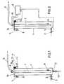
- FIG. 1shows an essentially cylindrical vessel 1, at the bottom area of which an inlet line 3 for supplying concentrate is provided, which can be closed by means of a valve 2. Furthermore, a feed line 10 for a rinsing liquid is arranged in the bottom area and can be closed by means of a valve 12.
- the cylindrical vessel 1has a ventilation device 4, in which a hydrophobic filter 8 is arranged. Furthermore, a drain 11 for rinsing liquid is connected to the upper area and can be closed by a valve 13.
- a concentrate suction tube 7can be inserted, which is connected to a cover 16 or a flange and is connected to a line 5 for discharging the liquid, which is usually connected to a hemodialysis machine.
- level sensors 6are mounted in the area of the concentrate suction pipe 7 or the line 5, which contribute to determining the amount of liquid in the cylindrical vessel 1 and to regulating it to a predetermined liquid level.
- the level sensors 6are designed, for example, in the form of conductivity sensors.
- a magnet 15is also attached to the cover 16, which serves to actuate a magnetic switch 14, with the aid of which an exact positioning of the concentration suction tube 7 can be determined.
- the valve 2is temporarily open in order to introduce a sufficient amount of liquid into the cylindrical vessel 1.
- the liquidis discharged through line 5, the valves 12 and 13 remain closed.
- the valve 2is closed, while the valves 12 and 13 are opened, so that a cleaning liquid can be introduced into the cylindrical vessel 1 and can be discharged both via the line 5 and via the discharge line 11.
- FIG. 2essentially corresponds to the exemplary embodiment according to FIG. 1, but differs from this in that no discharge line 11 or supply line 10 is provided for a rinsing liquid.
- a control device 9is also shown, which is connected in a suitable manner with the level sensors 6, the magnetic switch 14 and the valve 2 in order to ensure the above-described functioning of the pressure compensation vessel.
Landscapes
- Health & Medical Sciences (AREA)
- Heart & Thoracic Surgery (AREA)
- Urology & Nephrology (AREA)
- Anesthesiology (AREA)
- Vascular Medicine (AREA)
- Engineering & Computer Science (AREA)
- Emergency Medicine (AREA)
- Biomedical Technology (AREA)
- Hematology (AREA)
- Life Sciences & Earth Sciences (AREA)
- Animal Behavior & Ethology (AREA)
- General Health & Medical Sciences (AREA)
- Public Health (AREA)
- Veterinary Medicine (AREA)
- External Artificial Organs (AREA)
Description
Translated fromGermanDie Erfindung betrifft ein Druckausgleichsgefäß gemäß dem Oberbegriff des Anspruchs 1.The invention relates to a pressure compensation vessel according to the preamble of
Bei der Hämodialyse wird die Dialysierflüssigkeit üblicherweise durch Mischung von Dialysekonzentrat mit Wasser hergestellt.In hemodialysis, the dialysis liquid is usually prepared by mixing dialysis concentrate with water.
Bei der Herstellung oder Aufbereitung von Dialysierflüssigkeit werden zwei Verfahren unterschieden:A distinction is made between two processes for the production or preparation of dialysis fluid:
Bei dem ersten Verfahren erfolgt die Mischung mittels eines volumetrischen Mischverfahrens, bei welchem Wasser und Konzentrat in einem bestimmten vorgegebenen volumetrischen Verhältnis miteinander gemischt werden, beispielsweise in einem Verhältnis von 1:34.In the first method, the mixing takes place by means of a volumetric mixing method, in which water and concentrate are mixed with one another in a certain predetermined volumetric ratio, for example in a ratio of 1:34.
Ein zweites Verfahren zur Herstellung von Dialysierflüssigkeit ist das leitfähigkeitsgeregelte Verfahren, bei welchem das Verhältnis des Wasser- und Konzentratstroms so geregelt wird, daß sich in der fertigen Dialysierflüssigkeit eine gewisse Leitfähigkeit einstellt.A second method for producing dialysis fluid is the conductivity-controlled method, in which the ratio of the water and concentrate flow is regulated so that a certain conductivity is established in the finished dialysis fluid.
Üblicherweise wird die Dialysierflüssigkeit aus einem oder zwei Konzentraten und Wasser zubereitet, es ist jedoch auch möglich, die Dialysierflüssigkeit aus mehr als zwei Konzentraten und Wasser zuzubereiten.The dialysis fluid is usually made from one or two concentrates and water prepared, but it is also possible to prepare the dialysis liquid from more than two concentrates and water.
In der Praxis erfolgt die Bereitstellung des Dialysekonzentrats auf zwei unterschiedliche Arten. Zum einen ist es möglich, das Dialysekonzentrat, wie üblich, in Kanistern bereitzustellen und unter Verwendung einer Konzentratpumpe des Hämodialysegeräts anzusaugen und einer Mischeinrichtung zuzuführen in welcher das Dialysekonzentrat mit aufbereitetem Wasser gemischt wird. Diese Form der Aufbereitung der Dialysierflüssigkeit gestattet eine gewisse Flexibilität bei der Auswahl der Zusammensetzung der Dialysierflüssigkeit, bedingt andererseits jedoch einen erheblichen Arbeitsaufwand, um die Kanister zu transportieren, bereitzustellen und zu entsorgen. Weiterhin ist es jeweils erforderlich, die Kanister in geeigneter Weise mit einer Konzentratansaugleitung zu verbinden. Auch hieraus können sich Fehlerquellen ergeben. Ein beträchtliches Problem bereitet die Entsorgung der leeren Kanister, zum einen wegen der dabei auftretenden Abfallmenge als solcher und zum anderen wegen des relativ großen Volumens der leeren Kanister.In practice, the dialysis concentrate is provided in two different ways. On the one hand, it is possible, as usual, to provide the dialysis concentrate in canisters and to suck it in using a concentrate pump of the hemodialysis device and to feed it to a mixing device in which the dialysis concentrate is mixed with treated water. This form of preparation of the dialysis liquid allows a certain flexibility in the selection of the composition of the dialysis liquid, but on the other hand requires considerable work to transport, prepare and dispose of the canisters. Furthermore, it is necessary in each case to connect the canisters to a concentrate suction line in a suitable manner. This can also lead to sources of error. Disposal of the empty canisters presents a considerable problem, firstly because of the amount of waste as such and secondly because of the relatively large volume of the empty canisters.
Es wurden deshalb zentrale Konzentratversorgungen entwikkelt, bei welchen die Konzentrate von einem zentralen Behälter unter Druck zu jeweiligen Zapfstellen oder Anschlußstellen der Hämodialysegeräte gefördert werden.Central concentrate supplies have therefore been developed in which the concentrates are conveyed from a central container under pressure to the respective tapping points or connection points of the hemodialysis machines.
Die üblicherweise bei Hämodialysegeräten verwendeten Konzentratpumpen sind so aufgebaut, daß deren Förderrate vom Eingangsdruck beeinflußt wird. Es ist deshalb erforderlich, den üblicherweise schwankenden Druck einer zentralen Konzentratversorgung zu vergleichmäßigen, um die Föderrate der Mischpumpe nicht durch Druckschwankungen zu beeinträchtigen. Es wurden deshalb Druckausgleichsbehälter geschaffen, welche aus einem belüftbaren Gefäß sowie einem Niveauregelsystem bestehen. So werden beispielsweise Schwimmerschalter verwendet, um ein Konzentrateinlaßventil und/oder ein Ventil in einer Auslaßleitung zum Hämodialysegerät zu betätigen.The concentrate pumps commonly used in hemodialysis machines are designed so that their delivery rate is influenced by the inlet pressure. It is therefore necessary to even out the usually fluctuating pressure of a central concentrate supply so that the feed rate of the mixing pump is not affected by pressure fluctuations. Pressure equalization tanks were therefore created, which consist of a ventilated vessel and a level control system. For example, float switches are used to insert a concentrate inlet valve and / or a valve an outlet line to operate the hemodialysis machine.
Es sind aus dem Stand der Technik Druckausgleichsbehälter bekannt, welche seitlich am Ausgleichsgefäß oder im Boden desselben einen Anschluß für eine Konzentratansaugleitung aufweisen. Die Konzentratansaugleitung kann jedoch auch in Form eines Ansaugrohres ausgebildet sein, welches in einen Konzentratkanister eingeführt werden kann, sowie dies aus der DE-A1-37 34 880 bekannt ist.Pressure expansion tanks are known from the prior art, which have a connection for a concentrate suction line on the side of the expansion tank or in the bottom of the same. However, the concentrate suction line can also be designed in the form of a suction pipe which can be inserted into a concentrate canister, as is known from DE-A1-37 34 880.
Die DE-A1 beschreibt eine Vorrichtung für die Hämodialyse, bei welcher in einer Mischeinrichtung Konzentrat aus zwei Behältern mit Wasser gemischt wird. Die Behälter sind in beliebiger Form ausgebildet, das Konzentrat wird jeweils durch ein Ansaugrohr abgepumpt. Wie bereits erwähnt, stellt die gezeigte Zuführung des Konzentrates und dessen Abpumpung aus einem Konzentratkanister ein nicht für alle Anwendungsfälle geeignetes Prinzip dar. Insbesondere bei einer kontinuierlichen Zuführung von Konzentrat aus einem größeren Tank kann sich, bedingt durch die Ausgestaltung der Pumpen und der Leitungen die beschriebene Entlüftungsmöglichkeit als nicht ausreichend erweisen.DE-A1 describes a device for hemodialysis, in which concentrate from two containers is mixed with water in a mixing device. The containers are designed in any shape, the concentrate is pumped out through a suction pipe. As already mentioned, the supply of the concentrate shown and its pumping out of a concentrate canister is not a principle which is suitable for all applications. In particular with a continuous supply of concentrate from a larger tank, the described can occur due to the design of the pumps and the lines Venting option is not sufficient.
Der Erfindung liegt die Aufgabe zugrunde, ein Druckausgleichsgefäß der eingangs genannten Art zu schaffen, welches bei einfachem Aufbau und sicherer Wirkungsweise einen Druckausgleich in der Zuführung des Hämodialysekonzentrats gewährleistet und welches den Anschluß des Hämodialysegerätes an eine zentrale Konzentratversorgung ermöglicht.The invention has for its object to provide a pressure equalization vessel of the type mentioned, which ensures a pressure equalization in the supply of the hemodialysis concentrate with a simple structure and safe operation and which enables the connection of the hemodialysis machine to a central concentrate supply.
Die Aufgabe wird erfindungsgemäß durch die kennzeichnenden Merkmale des Anspruchs 1 gelöst.The object is achieved by the characterizing features of
Weitere vorteilhafte Ausgestaltungen der Erfindung ergeben sich aus den Unteransprüchen.Further advantageous embodiments of the invention result from the subclaims.
Das erfindungsgemäße Druckausgleichsgefäß zeichnet sich durch eine Reihe erheblicher Vorteile aus, so ist es erfindungsgemäß möglich, sowohl einen Druckausgleich vorzunehmen, als gleichzeitig ein bestimmtes Niveau des Hämodialysekonzentrats sicher zu stellen. Erfindungsgemäß ist es insbesondere möglich, die im Konzentratansaugrohr enthaltene bzw. diesem zugeordnete Niveaumeßeinrichtung zur Steuerung des Niveaus in dem Druckausgleichsgefäß zu verwenden.The pressure equalization vessel according to the invention is characterized by a number of considerable advantages, so that it is possible according to the invention both to carry out a pressure equalization and at the same time to ensure a certain level of the hemodialysis concentrate. According to the invention, it is in particular possible to use the level measuring device contained in or assigned to the concentrate suction pipe to control the level in the pressure compensation vessel.
Das erfindungsgemäße Druckausgleichsgefäß umfaßt ein im wesentlichen zylindrisches, aufrecht angeordnetes Gefäß, welches der Länge des Konzentratansaugerohrs angepaßt ist. Das zylindrische Rohr ist unten verschlossen und weist seitlich einen Einlaß für eine Konzentratzuführung auf. Der obere Bereich des zylindrischen Gefäßes ist offen, so daß das Konzentratansaugrohr eingesteckt werden kann, wobei dieses in gestecktem Zustand die Öffnung verdeckt, so daß keine Fremdkörper in das zylindrische Gefäß eindringen können. Für den Fall, daß das Konzentratansaugrohr entnommen wurde, kann das zylindrische Gefäß durch einen Deckel verschlossen werden. Weiterhin ist im oberen Bereich des zylindrischen Gefäßes eine Entlüftungsöffnung vorgesehen, welche vorteilhafterweise mittels einer hydrophoben Membran verschlossen ist.The pressure compensation vessel according to the invention comprises a substantially cylindrical, upright vessel which is adapted to the length of the concentrate suction tube. The cylindrical tube is closed at the bottom and points to the side an inlet for a concentrate feed. The upper area of the cylindrical vessel is open, so that the concentrate suction tube can be inserted, which, when plugged in, covers the opening so that no foreign objects can penetrate into the cylindrical vessel. In the event that the concentrate suction tube has been removed, the cylindrical vessel can be closed by a lid. Furthermore, a ventilation opening is provided in the upper region of the cylindrical vessel, which is advantageously closed by means of a hydrophobic membrane.
Die Einlaßleitung im Bodenbereich des zylindrischen Gefäßes ist bevorzugterweise mittels eines Ventils zu öffnen bzw. zu verschließen. Mittels der Steuereinrichtung des Hämodialysegerätes ist es möglich, das Ventil aufgrund eines Signals des im Ansaugrohr intergrierten Niveausensors so zu steuern, daß das Konzentratflüssigkeitsniveau annähernd konstant bleibt und möglichst gering gehalten wird.The inlet line in the bottom region of the cylindrical vessel is preferably to be opened or closed by means of a valve. By means of the control device of the hemodialysis machine, it is possible to control the valve based on a signal from the level sensor integrated in the suction tube in such a way that the concentrate liquid level remains approximately constant and is kept as low as possible.
Sofern bei dem erfindungsgemäßen Druckausgleichsgefäß nur ein Niveausensor verwendet wird, welcher eine einzige Schaltschwelle besitzt, pendelt das Flüssigkeitsniveau um diese Schaltschwelle.If only one level sensor is used in the pressure compensation vessel according to the invention, which has a single switching threshold, the liquid level oscillates around this switching threshold.
Bevorzugterweise ist erfindungsgemäß vorgesehen, daß eine Alarmeinrichtung betätigt wird, sofern nach Öffnen des Konzentrateingangsventils die Schaltschwelle des Niveausensors nicht innerhalb einer bestimmten Zeit überschritten wird. Dabei wird das Ventil geschlossen, um den Benutzer auf eine Störung hinzuweisen.According to the invention, it is preferably provided that an alarm device is actuated provided the switching threshold of the level sensor is not exceeded within a certain time after opening the concentrate inlet valve. The valve is closed to inform the user of a malfunction.
Bei einer derartigen Störung kann es sich entweder um eine Unterbrechung des Konzentratflusses handeln, bei welcher das Druckausgleichgefäß nicht mehr ausreichend befüllt wird, es ist jedoch auch möglich, daß der Niveausensor einen Defekt aufweist. Der letztere Fall würde dazu führen, daß durch das Konzentrat die hydrophobe Membran verstopft würde, so daß keine ausreichende Entlüftung stattfinden könnte.Such a fault can either be an interruption of the concentrate flow, in which the pressure compensation vessel is no longer adequately filled, but it is also possible that the level sensor has a defect. The latter case would result in the concentrate blocking the hydrophobic membrane, so that adequate ventilation could not take place.
Hinsichtlich des Niveausensors, welcher im Ansaugrohr integriert ist, ist es möglich, diesen so auszubilden, wie dies in der DE-OS 37 34 880 beschrieben ist.With regard to the level sensor, which is integrated in the intake pipe, it is possible to design it as described in DE-OS 37 34 880.
Erfindungsgemäß ist es möglich, den Niveausensor, wie bekannt, in Form eines Leitfähigkeitsensor auszubilden. Der Niveausensor kann jedoch auch als faseroptischer Sensor ausgestaltet sein, um beispielsweise die optische Drehung des Konzentrats oder das Niveau in bekannter Weise über Totalreflexierung zu detektieren bzw. zu messen. Es ist jedoch auch möglich, den Niveausensor als Dichtesensor oder als Vibrationssensor auszubilden.According to the invention, it is possible, as is known, to design the level sensor in the form of a conductivity sensor. However, the level sensor can also be designed as a fiber optic sensor, for example to detect or measure the optical rotation of the concentrate or the level in a known manner via total reflection. However, it is also possible to design the level sensor as a density sensor or as a vibration sensor.
In einer besonders günstigen Ausgestaltung der Erfindung ist vorgesehen, daß das zylindrische Gefäß in Form eines im Hämodialysegerät integrierten Gefäßes ausgebildet ist, mittels dessen, das Ansaugrohr während der Desinfektions- und Reinigungsphase desinfizierbar und reinigbar ist. Diese Ausgestaltung weist den entscheidenden Vorteil auf, daß kein zusätzliches Gefäß verwendet werden muß, da das bereits bekannte Desinfektions- und Reinigungsgefäß nach entsprechender Umgestaltung zugleich als Druckausgleichsgefäß verwendet werden kann.In a particularly favorable embodiment of the invention it is provided that the cylindrical vessel is designed in the form of a vessel integrated in the hemodialysis machine, by means of which the suction tube can be disinfected and cleaned during the disinfection and cleaning phase. This configuration has the decisive advantage that no additional vessel has to be used, since the already known disinfection and cleaning vessel can also be used as a pressure compensation vessel after a corresponding redesign.
Im letzten Fall ist es erforderlich zwei weitere Anschlußleitungen an dem zylindrischen Gefäß vozusehen, welche über Ventile geöffnet bzw. geschlossen werden können. Die Zuleitung bzw. Ableitung dient zur Zuführung bzw. Abführung von Reinigungsflüssigkeit.In the latter case, it is necessary to provide two further connecting lines on the cylindrical vessel, which can be opened or closed via valves. The supply line or discharge line is used to supply or discharge cleaning fluid.
In letztgenannten Ausgestaltungsfall ist es besonders günstig, wenn das Druckausgleichgefäß so im Dialysierflüssigkeitskreislauf angeschlossen ist, daß es stromab des Dialysators noch vor einem eventuellen Rezirkulationskreislauf angeordnet ist.In the latter embodiment, it is particularly advantageous if the pressure compensation vessel is connected in the dialysis fluid circuit in such a way that it is arranged downstream of the dialyzer before a possible recirculation circuit.
Die Zuleitung bzw. Ableitung ist so angeordnet, daß das zylindrische Gefäß von der Reinigungsflüssigkeit voll oder im Nebenstrom durchspült werden kann und gleichzeitig die Reinigungsflüssigkeit auch von der Konzentratpumpe angesaugt werden kann. Während der Desinfektions- und Reinigungsphase bleibt das Ventil in der Konzentrationsflüssigkeitszuleitung geschlossen, weiterhin wird die Niveaumeßschaltung ausgeschaltet. Während der Dialyse sind die beiden Ventile in der Zuleitung bzw. Ableitung der Reinigungsflüssigkeit geschlossen, während das Ventil in der Konzentratszuleitung geöffnet ist.The supply line or discharge line is arranged so that the cleaning liquid can flush through the cylindrical vessel completely or in the bypass flow and at the same time the cleaning liquid can also be sucked in by the concentrate pump. During the disinfection and cleaning phase, the valve in the concentration liquid supply line remains closed, and the level measurement circuit is switched off. During dialysis, the two valves in the supply line or the discharge line of the cleaning liquid are closed, while the valve in the concentrate supply line is open.
In einer weiteren, besonders günstigen Ausgestaltung der Erfindung ist vorgesehen, daß an dem Druckausgleichsgefäß eine Sensoreinrichtung angeordnet ist, mittels derer festgestellt werden kann, ob das Konzentratansaugrohr in korrekter Weise in das zylindrische Gefäß eingesteckt bzw. an diesem fixiert ist. Die Sensoreinrichtung kann beispielsweise einen Magnetschalter umfassen, welcher durch einen an dem Konzentratansaugrohr befestigten Magnet betätigt wird. Dabei kann der Magnetschalter bzw. die Sensoreinrichtung so mit der Steuereinrichtung verbunden sein, daß das Konzentrateinlaßventil nur dann angesteuert werden kann, wenn das Konzentratansaugrohr in korrekter Weise angeordnet ist.In a further, particularly advantageous embodiment of the invention, it is provided that a sensor device is arranged on the pressure compensation vessel, by means of which it can be determined whether the concentrate suction tube is correctly inserted into the cylindrical vessel or is fixed thereon. The sensor device can comprise, for example, a magnetic switch, which is actuated by a magnet attached to the concentrate suction pipe. The magnetic switch or the sensor device can be connected to the control device in such a way that the concentrate inlet valve can only be activated if the concentrate suction pipe is arranged in the correct manner.
Bei dem letztbeschriebenen Ausführungsbeispiel, bei welchem das zylindrische Gefäß zugleich zur Desinfektion oder Reinigung dienen kann, ist es möglich, die zentrale Konzentratversorgung stets in einem angeschlossenen Zustand zu belassen. Es ist ohne mechanische Betätigung, das heißt ohne Umstecken von Rohrverbindungen oder ähnlichem möglich, eine Dialyse durchzuführen und nachfolgend das Dialysegerät zu spülen bzw. zu desinfizieren und für die nächste Hämodialyse vorzubereiten.In the last described embodiment, in which the cylindrical vessel can also be used for disinfection or cleaning, it is possible to always leave the central concentrate supply in a connected state. It is possible to carry out dialysis without mechanical actuation, that is to say without repositioning pipe connections or the like, and subsequently rinsing or disinfecting the dialysis machine and preparing it for the next hemodialysis.
Zusätzlich ist es jedoch auch möglich, das Konzentratansaugrohr in einen Kanister zur Bereitstellung von Konzentratflüssigkeit einzubringen.In addition, however, it is also possible to insert the concentrate suction pipe into a canister for providing concentrate liquid.
Im Folgenden wird die Erfindung anhand zweier Ausführungsbeispiele in Verbindung mit der Zeichnung beschrieben. Dabei zeigt:
- Fig. 1
- eine schematische Seitenansicht eines ersten Ausführungsbeispiels des erfindungsgemäßen Druckausgleichsgefäßes und
- Fig. 2
- eine schematische Darstellung eines zweiten Ausführungsbeispiels des erfindungsgemäßen Druckausgleichsgefäßes.
- Fig. 1
- is a schematic side view of a first embodiment of the pressure compensation vessel according to the invention and
- Fig. 2
- is a schematic representation of a second embodiment of the pressure compensation vessel according to the invention.
In Fig. 1 ist ein im wesentlichen zylindrisches Gefäß 1 dargestellt, an dessen Bodenbereich eine Einlaßleitung 3 zur Zuführung von Konzentrat vorgesehen ist, welche mittels eines Ventils 2 verschließbar ist. Weiterhin ist im Bodenbereich eine Zuleitung 10 für eine Spülflüssigkeit angeordnet, welche mittels eines Ventils 12 verschließbar ist.1 shows an essentially
Am oberen Bereich weist das zylindrische Gefäß 1 eine Entlüftungseinrichtung 4 auf, in welcher ein hydrophobes Filter 8 angeordnet ist. Weiterhin ist am oberen Bereich eine Ableitung 11 für Spülflüssigkeit angeschlossen, welche über ein Ventil 13 verschließbar ist.At the top, the
In das zylindrische Gefäß 1 ist ein Konzentratansaugrohr 7 einsteckbar, welches mit einem Deckel 16 oder einem Flansch verbunden ist und mit einer Leitung 5 zur Abführung der Flüssigkeit in Verbidnung steht, welche üblicherweise an ein Hämodialysegerät angeschlossen ist.In the
Im Bereich des Konzentratansaugrohrs 7 bzw. der Leitung 5 sind bei dem gezeigten Ausführungsbeispiel Niveausensoren 6 gelagert, welche zu einer Bestimmung der Flüssigkeitsmenge in dem zylindrischen Gefäß 1 und zu einer Regelung auf ein vorgegebenes Flüssigkeitsniveau beitragen. Die Niveausensoren 6 sind beispielsweise in Form von Leitfähigkeitsensoren ausgebildet.In the embodiment shown,
An dem Deckel 16 ist weiterhin ein Magnet 15 befestigt, welcher zur Betätigung eines Magnetschalters 14 dient, mit Hilfe dessen eine exakte Positionierung des Konzentrations-Ansaugrohrs 7 ermittelbar ist.A
Während der Dialyse ist das Ventil 2 zeitweise geöffnet, um eine ausreichende Flüssigkeitsmenge in das zylindrische Gefäß 1 einzuführen. Die Flüssigkeit wird durch die Leitung 5 abgeführt, die Ventile 12 und 13 bleiben geschlossen. Während der Spülphase wird das Ventil 2 geschlossen, während die Ventile 12 und 13 geöffnet werden, so daß eine Reinigungsflüssigkeit in das zylindrische Gefäß 1 eingeleitet und sowohl über die Leitung 5 als auch über die Ableitung 11 abgeführt werden kann.During the dialysis, the
Das in Fig. 2 gezeigte Ausführungsbeipiel entspricht im wesentlichen dem Ausführungsbeispiel gemäß Fig. 1, unterscheidet sich von diesem jedoch darin, daß keine Ableitung 11 bzw. Zuleitung 10 für eine Spülflüssigkeit vorgesehen ist.The embodiment shown in FIG. 2 essentially corresponds to the exemplary embodiment according to FIG. 1, but differs from this in that no
In Fig. 2 ist weiterhin eine Steuereinrichtung 9 abgebildet, welche in geeigneter Weise mit den Niveausensoren 6, dem Magnetschalter 14 sowie dem Ventil 2 in Verbindung steht, um die oben beschriebene Funktionsweise des Druckausgleichsgefäßes zu gewährleisten.In Fig. 2, a control device 9 is also shown, which is connected in a suitable manner with the
Die Erfindung ist nicht auf die gezeigten Ausführungbeispiele beschränkt, vielmehr ergeben sich im Rahmen der Erfindung vielfältige Abwandlungs- und Modifikationsmöglichkeiten.The invention is not limited to the exemplary embodiments shown, but there are many possible modifications and modifications within the scope of the invention.
Claims (12)
- A pressure equalizing vessel for a hemodialysis concentrate, comprising an upright vessel (1) whose upper portion is equipped with a venting means (4), and comprising a conduit (5) arranged on the upper portion thereof for discharging the concentrate to a hemodialysis device, wherein said conduit (5) is connected with a concentrate suction tube (7),
characterized in
that said vessel (1) is substantially cylindrical, that at the lower portion of said vessel (1) a concentrate inlet (3) provided with a valve (2) is arranged and that the concentrate suction tube (7) is provided with at least one level sensor (6). - The pressure equalizing vessel according to claim 1, characterized in that said concentrate suction tube (7) can be withdrawn from said cylindrical vessel (1) and that said cylindrical vessel (1) can be closed by means of a cover.
- The pressure equalizing vessel according to claim 1 or 2, characterized in that said venting means (4) is closed by a hydrophobic filter (8).
- The pressure equalizing vessel according to any of claims 1 to 3, characterized in that said valve (2) arranged in said concentrate inlet (3) is adapted to be actuated by a control means (9) to which signals from said level sensor (6) are supplied.
- The pressure equalizing vessel according to any of claims 1 to 4, characterized in that said level sensor (6) is designed in the form of a conductivity sensor.
- The pressure equalizing vessel according to any of claims 1 to 4, characterized in that said level sensor (6) is designed in the form of a fiber-optical sensor.
- The pressure equalizing vessel according to any of claims 1 to 4, characterized in that said level sensor (6 ) is designed in the form of a vibration sensor.
- The pressure equalizing vessel according to any of claims 1 to 7, characterized in that said cylindrical vessel (1) is designed in the form of a vessel which is integrated in said hemodialysis device and by means of which said suction tube (7) can be disinfected and cleansed in the disinfecting and cleansing phase.
- The pressure equalizing vessel according to claim 8, characterized in that said cylindrical vessel (1) is provided with a flushing liquid supply conduit (10) and a flushing liquid discharge conduit (11) which have arranged therein valves (12, 13) and which are connected in the dialyzing liquid circuit.
- The pressure equalizing vessel according to claim 9, characterized in that said supply conduit (10) and said discharge conduit (11) are provided on opposite portions of said cylindrical vessel (1).
- The pressure equalizing vessel according to any of claims 1 to 10, characterized in that a sensing means is provided for sensing the proper arrangement of said concentrate suction tube (7) on said cylindrical vessel (1).
- The pressure equalizing vessel according to claim 11, characterized in that said sensing means comprises a magnetic switch (14).
Applications Claiming Priority (2)
| Application Number | Priority Date | Filing Date | Title |
|---|---|---|---|
| DE3930181 | 1989-09-09 | ||
| DE3930181ADE3930181A1 (en) | 1989-09-09 | 1989-09-09 | PRESSURE COMPENSATING VESSEL FOR A HEMODIALYSIS CONCENTRATE |
Publications (2)
| Publication Number | Publication Date |
|---|---|
| EP0417579A1 EP0417579A1 (en) | 1991-03-20 |
| EP0417579B1true EP0417579B1 (en) | 1993-11-03 |
Family
ID=6389101
Family Applications (1)
| Application Number | Title | Priority Date | Filing Date |
|---|---|---|---|
| EP90116804AExpired - LifetimeEP0417579B1 (en) | 1989-09-09 | 1990-09-01 | Surge tank for a haemodialysis concentrate |
Country Status (5)
| Country | Link |
|---|---|
| US (1) | US5178179A (en) |
| EP (1) | EP0417579B1 (en) |
| JP (1) | JPH03121075A (en) |
| DE (2) | DE3930181A1 (en) |
| ES (1) | ES2045695T3 (en) |
Families Citing this family (3)
| Publication number | Priority date | Publication date | Assignee | Title |
|---|---|---|---|---|
| DE4203905C2 (en)* | 1992-02-11 | 1993-12-09 | Fresenius Ag | Device for the central supply of dialysis stations with dialysis concentrate |
| WO2004058334A1 (en)* | 2002-12-23 | 2004-07-15 | Medtronic, Inc. | Implantable drug delivery systems and methods |
| US11260156B2 (en) | 2019-11-27 | 2022-03-01 | Fresenius Medical Care Holdings, Inc. | Pressure relief mechanism for sorbent canisters |
Family Cites Families (16)
| Publication number | Priority date | Publication date | Assignee | Title |
|---|---|---|---|---|
| GB859104A (en)* | 1958-04-10 | 1961-01-18 | Bendix Corp | Level sensors |
| FR1568072A (en)* | 1968-01-24 | 1969-05-23 | ||
| US3508656A (en)* | 1968-04-10 | 1970-04-28 | Milton Roy Co | Portable dialysate supply system |
| DE2636290A1 (en)* | 1976-08-12 | 1978-02-16 | Fresenius Chem Pharm Ind | DEVICE FOR CONTROLLING AND MONITORING BLOOD FLOW DURING BLOOD DIALYSIS, PERFUSION AND DIAFILTRATION USING ONLY ONE CONNECTION POINT TO THE PATIENT'S BLOOD CIRCUIT (SINGLE NEEDLE TECHNOLOGY) |
| US4085046A (en)* | 1976-08-16 | 1978-04-18 | Saporito Jr Thomas J | Renal dialysis concentrate delivery system |
| US4717548A (en)* | 1980-06-09 | 1988-01-05 | The United States Of America As Represented By The Secretary Of The Department Of Health And Human Services | Analytically controlled blood perfusion system |
| DE3140485A1 (en)* | 1981-10-12 | 1983-04-28 | Jagenberg-Werke AG, 4000 Düsseldorf | DEVICE FOR DELIVERING VERY SMALL LIQUID QUANTITIES |
| US4521685A (en)* | 1982-03-01 | 1985-06-04 | Lord Corporation | Tactile sensor for an industrial robot or the like |
| DE3215003C2 (en)* | 1982-04-22 | 1985-04-04 | Fresenius AG, 6380 Bad Homburg | Process for separating air from a dialysis fluid and dialysis machine |
| US4747822A (en)* | 1984-07-09 | 1988-05-31 | Peabody Alan M | Continuous flow peritoneal dialysis system and method |
| DE3443911C2 (en)* | 1984-12-01 | 1994-06-01 | Andreas Alexander Dr Med Mund | Device for the production of liquid concentrate from powdered concentrate salt for the preparation of dialysis fluid |
| US4681563A (en)* | 1985-04-26 | 1987-07-21 | Centaur Sciences, Inc. | Flow control system |
| SE459641B (en)* | 1986-03-24 | 1989-07-24 | Gambro Ab | DETECTOR SYSTEM CONTROLS A BLOOD CIRCULATION ALTERNATIVE WITH A SIGNIFICANTLY UNLESSED |
| DE3637771C1 (en)* | 1986-11-06 | 1987-12-10 | Braun Melsungen Ag | Infusion device |
| DE3734880C1 (en)* | 1987-10-15 | 1989-03-23 | Fresenius Ag | Device for hemodialysis with protection system against incorrect composition of the dialysis fluid |
| DE3740598C2 (en)* | 1987-11-30 | 1998-03-26 | Grieshaber Vega Kg | Vibrating unit for level vibration limit switch |
- 1989
- 1989-09-09DEDE3930181Apatent/DE3930181A1/enactiveGranted
- 1990
- 1990-09-01ESES90116804Tpatent/ES2045695T3/ennot_activeExpired - Lifetime
- 1990-09-01DEDE90116804Tpatent/DE59003327D1/ennot_activeExpired - Fee Related
- 1990-09-01EPEP90116804Apatent/EP0417579B1/ennot_activeExpired - Lifetime
- 1990-09-10USUS07/579,641patent/US5178179A/ennot_activeExpired - Fee Related
- 1990-09-10JPJP2239785Apatent/JPH03121075A/enactivePending
Also Published As
| Publication number | Publication date |
|---|---|
| JPH03121075A (en) | 1991-05-23 |
| DE3930181A1 (en) | 1991-03-21 |
| US5178179A (en) | 1993-01-12 |
| DE59003327D1 (en) | 1993-12-09 |
| DE3930181C2 (en) | 1993-01-14 |
| EP0417579A1 (en) | 1991-03-20 |
| ES2045695T3 (en) | 1994-01-16 |
Similar Documents
| Publication | Publication Date | Title |
|---|---|---|
| EP1323439B1 (en) | Device for on-line cleaning and filling or emptying of an extra corporeal blood circuit of a dialysis apparatus | |
| EP0543283B1 (en) | Disinfection device for hemodialysis apparatus | |
| EP0622086B1 (en) | Safety hydraulic circuit for an hemodialysis machine | |
| DE69109012T2 (en) | Device for dissolving a correction medium for a dialytic solution. | |
| DE3442744C2 (en) | ||
| DE3641843C2 (en) | ||
| EP0367252B1 (en) | Method and apparatus for ultrafiltration during hemodialysis | |
| DE19655225B4 (en) | Method for operating a modular home dialysis system | |
| DE2929804C2 (en) | Dental suction device | |
| DE3416955A1 (en) | HAEMODIALYSIS DEVICE | |
| EP0417579B1 (en) | Surge tank for a haemodialysis concentrate | |
| DE3447989C2 (en) | ||
| EP0884966B1 (en) | System for making a floor cleaning liquid available in a convenient manner | |
| EP1514563B1 (en) | Connection device for sterilant or cleaning agent | |
| EP3694576A1 (en) | Device and method for degassing of dialysis concentrates for automatic density measurement in mixing installations | |
| EP1454643A1 (en) | Method of operating a dialysis device | |
| DE3410826C2 (en) | Level control and safety device for dishwashers and washing machines | |
| EP0802721B1 (en) | Device for separating milk yields of particular cows | |
| DE4321008C1 (en) | Haemodialysis unit hydraulic circuit with cleaning or disinfectant circuit - applies preset pressure to buffer volume formed between non-return valve and magnetic stop valve, and couples pressure sensor between volume and microprocessor | |
| EP0709666B1 (en) | Device for withdrawing a representative milk sample | |
| WO1999035996A1 (en) | Device and method for cleaning teeth and gums | |
| EP3383450B1 (en) | Method for testing the rigidity of a disposable | |
| DE69612620T2 (en) | DEVICE FOR SUCTIONING BACK WATER FROM AN EXHAUST PIPE IN CONNECTION WITH A WATER CLEANER | |
| EP4623945A1 (en) | Container assembly for producing and providing an alkalinesing solution, and extracorporeal blood treatment machine comprising the container assembly | |
| DE102024103806A1 (en) | Dialysis unit and method for preparing dialysis therapy |
Legal Events
| Date | Code | Title | Description |
|---|---|---|---|
| PUAI | Public reference made under article 153(3) epc to a published international application that has entered the european phase | Free format text:ORIGINAL CODE: 0009012 | |
| AK | Designated contracting states | Kind code of ref document:A1 Designated state(s):DE ES FR GB IT | |
| 17P | Request for examination filed | Effective date:19910516 | |
| 17Q | First examination report despatched | Effective date:19920813 | |
| GRAA | (expected) grant | Free format text:ORIGINAL CODE: 0009210 | |
| AK | Designated contracting states | Kind code of ref document:B1 Designated state(s):DE ES FR GB IT | |
| GBT | Gb: translation of ep patent filed (gb section 77(6)(a)/1977) | Effective date:19931109 | |
| REF | Corresponds to: | Ref document number:59003327 Country of ref document:DE Date of ref document:19931209 | |
| REG | Reference to a national code | Ref country code:ES Ref legal event code:FG2A Ref document number:2045695 Country of ref document:ES Kind code of ref document:T3 | |
| ITF | It: translation for a ep patent filed | ||
| ET | Fr: translation filed | ||
| PLBE | No opposition filed within time limit | Free format text:ORIGINAL CODE: 0009261 | |
| STAA | Information on the status of an ep patent application or granted ep patent | Free format text:STATUS: NO OPPOSITION FILED WITHIN TIME LIMIT | |
| 26N | No opposition filed | ||
| REG | Reference to a national code | Ref country code:GB Ref legal event code:IF02 | |
| PGFP | Annual fee paid to national office [announced via postgrant information from national office to epo] | Ref country code:FR Payment date:20040917 Year of fee payment:15 | |
| PGFP | Annual fee paid to national office [announced via postgrant information from national office to epo] | Ref country code:ES Payment date:20040923 Year of fee payment:15 | |
| PGFP | Annual fee paid to national office [announced via postgrant information from national office to epo] | Ref country code:DE Payment date:20041125 Year of fee payment:15 | |
| PGFP | Annual fee paid to national office [announced via postgrant information from national office to epo] | Ref country code:GB Payment date:20050816 Year of fee payment:16 | |
| PG25 | Lapsed in a contracting state [announced via postgrant information from national office to epo] | Ref country code:IT Free format text:LAPSE BECAUSE OF NON-PAYMENT OF DUE FEES Effective date:20050901 | |
| PG25 | Lapsed in a contracting state [announced via postgrant information from national office to epo] | Ref country code:ES Free format text:LAPSE BECAUSE OF NON-PAYMENT OF DUE FEES Effective date:20050902 | |
| PG25 | Lapsed in a contracting state [announced via postgrant information from national office to epo] | Ref country code:DE Free format text:LAPSE BECAUSE OF NON-PAYMENT OF DUE FEES Effective date:20060401 | |
| PG25 | Lapsed in a contracting state [announced via postgrant information from national office to epo] | Ref country code:FR Free format text:LAPSE BECAUSE OF NON-PAYMENT OF DUE FEES Effective date:20060531 | |
| REG | Reference to a national code | Ref country code:FR Ref legal event code:ST Effective date:20060531 | |
| REG | Reference to a national code | Ref country code:ES Ref legal event code:FD2A Effective date:20050902 | |
| GBPC | Gb: european patent ceased through non-payment of renewal fee | Effective date:20060901 | |
| PG25 | Lapsed in a contracting state [announced via postgrant information from national office to epo] | Ref country code:GB Free format text:LAPSE BECAUSE OF NON-PAYMENT OF DUE FEES Effective date:20060901 |