EP0413119A2 - Center open large rolling bearing - Google Patents
Center open large rolling bearingDownload PDFInfo
- Publication number
- EP0413119A2 EP0413119A2EP90112660AEP90112660AEP0413119A2EP 0413119 A2EP0413119 A2EP 0413119A2EP 90112660 AEP90112660 AEP 90112660AEP 90112660 AEP90112660 AEP 90112660AEP 0413119 A2EP0413119 A2EP 0413119A2
- Authority
- EP
- European Patent Office
- Prior art keywords
- ring
- center
- coupling surface
- roller bearing
- bearing according
- Prior art date
- Legal status (The legal status is an assumption and is not a legal conclusion. Google has not performed a legal analysis and makes no representation as to the accuracy of the status listed.)
- Granted
Links
Images
Classifications
- F—MECHANICAL ENGINEERING; LIGHTING; HEATING; WEAPONS; BLASTING
- F16—ENGINEERING ELEMENTS AND UNITS; GENERAL MEASURES FOR PRODUCING AND MAINTAINING EFFECTIVE FUNCTIONING OF MACHINES OR INSTALLATIONS; THERMAL INSULATION IN GENERAL
- F16C—SHAFTS; FLEXIBLE SHAFTS; ELEMENTS OR CRANKSHAFT MECHANISMS; ROTARY BODIES OTHER THAN GEARING ELEMENTS; BEARINGS
- F16C19/00—Bearings with rolling contact, for exclusively rotary movement
- F16C19/22—Bearings with rolling contact, for exclusively rotary movement with bearing rollers essentially of the same size in one or more circular rows, e.g. needle bearings
- F16C19/34—Bearings with rolling contact, for exclusively rotary movement with bearing rollers essentially of the same size in one or more circular rows, e.g. needle bearings for both radial and axial load
- F16C19/38—Bearings with rolling contact, for exclusively rotary movement with bearing rollers essentially of the same size in one or more circular rows, e.g. needle bearings for both radial and axial load with two or more rows of rollers
- F16C19/381—Bearings with rolling contact, for exclusively rotary movement with bearing rollers essentially of the same size in one or more circular rows, e.g. needle bearings for both radial and axial load with two or more rows of rollers with at least one row for radial load in combination with at least one row for axial load
- B—PERFORMING OPERATIONS; TRANSPORTING
- B66—HOISTING; LIFTING; HAULING
- B66C—CRANES; LOAD-ENGAGING ELEMENTS OR DEVICES FOR CRANES, CAPSTANS, WINCHES, OR TACKLES
- B66C23/00—Cranes comprising essentially a beam, boom, or triangular structure acting as a cantilever and mounted for translatory of swinging movements in vertical or horizontal planes or a combination of such movements, e.g. jib-cranes, derricks, tower cranes
- B66C23/62—Constructional features or details
- B66C23/84—Slewing gear
- F—MECHANICAL ENGINEERING; LIGHTING; HEATING; WEAPONS; BLASTING
- F16—ENGINEERING ELEMENTS AND UNITS; GENERAL MEASURES FOR PRODUCING AND MAINTAINING EFFECTIVE FUNCTIONING OF MACHINES OR INSTALLATIONS; THERMAL INSULATION IN GENERAL
- F16C—SHAFTS; FLEXIBLE SHAFTS; ELEMENTS OR CRANKSHAFT MECHANISMS; ROTARY BODIES OTHER THAN GEARING ELEMENTS; BEARINGS
- F16C19/00—Bearings with rolling contact, for exclusively rotary movement
- F16C19/52—Bearings with rolling contact, for exclusively rotary movement with devices affected by abnormal or undesired conditions
- G—PHYSICS
- G01—MEASURING; TESTING
- G01N—INVESTIGATING OR ANALYSING MATERIALS BY DETERMINING THEIR CHEMICAL OR PHYSICAL PROPERTIES
- G01N29/00—Investigating or analysing materials by the use of ultrasonic, sonic or infrasonic waves; Visualisation of the interior of objects by transmitting ultrasonic or sonic waves through the object
- G01N29/04—Analysing solids
- G01N29/043—Analysing solids in the interior, e.g. by shear waves
- F—MECHANICAL ENGINEERING; LIGHTING; HEATING; WEAPONS; BLASTING
- F16—ENGINEERING ELEMENTS AND UNITS; GENERAL MEASURES FOR PRODUCING AND MAINTAINING EFFECTIVE FUNCTIONING OF MACHINES OR INSTALLATIONS; THERMAL INSULATION IN GENERAL
- F16C—SHAFTS; FLEXIBLE SHAFTS; ELEMENTS OR CRANKSHAFT MECHANISMS; ROTARY BODIES OTHER THAN GEARING ELEMENTS; BEARINGS
- F16C2233/00—Monitoring condition, e.g. temperature, load, vibration
- F—MECHANICAL ENGINEERING; LIGHTING; HEATING; WEAPONS; BLASTING
- F16—ENGINEERING ELEMENTS AND UNITS; GENERAL MEASURES FOR PRODUCING AND MAINTAINING EFFECTIVE FUNCTIONING OF MACHINES OR INSTALLATIONS; THERMAL INSULATION IN GENERAL
- F16C—SHAFTS; FLEXIBLE SHAFTS; ELEMENTS OR CRANKSHAFT MECHANISMS; ROTARY BODIES OTHER THAN GEARING ELEMENTS; BEARINGS
- F16C2300/00—Application independent of particular apparatuses
- F16C2300/10—Application independent of particular apparatuses related to size
- F16C2300/14—Large applications, e.g. bearings having an inner diameter exceeding 500 mm
- F—MECHANICAL ENGINEERING; LIGHTING; HEATING; WEAPONS; BLASTING
- F16—ENGINEERING ELEMENTS AND UNITS; GENERAL MEASURES FOR PRODUCING AND MAINTAINING EFFECTIVE FUNCTIONING OF MACHINES OR INSTALLATIONS; THERMAL INSULATION IN GENERAL
- F16C—SHAFTS; FLEXIBLE SHAFTS; ELEMENTS OR CRANKSHAFT MECHANISMS; ROTARY BODIES OTHER THAN GEARING ELEMENTS; BEARINGS
- F16C33/00—Parts of bearings; Special methods for making bearings or parts thereof
- F16C33/30—Parts of ball or roller bearings
- F16C33/58—Raceways; Race rings
- F16C33/60—Raceways; Race rings divided or split, e.g. comprising two juxtaposed rings
- G—PHYSICS
- G01—MEASURING; TESTING
- G01N—INVESTIGATING OR ANALYSING MATERIALS BY DETERMINING THEIR CHEMICAL OR PHYSICAL PROPERTIES
- G01N2291/00—Indexing codes associated with group G01N29/00
- G01N2291/04—Wave modes and trajectories
- G01N2291/044—Internal reflections (echoes), e.g. on walls or defects
- G—PHYSICS
- G01—MEASURING; TESTING
- G01N—INVESTIGATING OR ANALYSING MATERIALS BY DETERMINING THEIR CHEMICAL OR PHYSICAL PROPERTIES
- G01N2291/00—Indexing codes associated with group G01N29/00
- G01N2291/10—Number of transducers
- G01N2291/102—Number of transducers one emitter, one receiver
- G—PHYSICS
- G01—MEASURING; TESTING
- G01N—INVESTIGATING OR ANALYSING MATERIALS BY DETERMINING THEIR CHEMICAL OR PHYSICAL PROPERTIES
- G01N2291/00—Indexing codes associated with group G01N29/00
- G01N2291/26—Scanned objects
- G01N2291/269—Various geometry objects
- G—PHYSICS
- G01—MEASURING; TESTING
- G01N—INVESTIGATING OR ANALYSING MATERIALS BY DETERMINING THEIR CHEMICAL OR PHYSICAL PROPERTIES
- G01N2291/00—Indexing codes associated with group G01N29/00
- G01N2291/26—Scanned objects
- G01N2291/269—Various geometry objects
- G01N2291/2696—Wheels, Gears, Bearings
Definitions
- the inventionrelates to a center-free slewing bearing according to the preamble of claim 1.
- EP A1 228 731it is proposed to arrange at least one opening in at least one bearing ring, into which an ultrasound probe can be inserted. Material defects in this other bearing ring are then to be identified via a coupling surface on the other bearing ring.
- a disadvantage of this designis that the ultrasound probe is used in the area of the raceways. As a result, it is necessary to at least partially remove the grease in this area and to partially clean the coupling surface. Abrasion particles that also separate in this area can also lead to incorrect measurements. Furthermore, if the bearing is in operation for a longer period of time, there is an increase in the bearing play due to the permissible wear. This increased bearing play shifts the coupling surface to the position of the ultrasound probe, which can also lead to incorrect measurements.
- the inventionhas for its object to avoid the disadvantages described above and to design the bearing so that a simple and safe ultrasonic measurement is possible.
- the design of a large roller bearing according to the inventionadvantageously enables a simple arrangement of ultrasonic probes. It is no longer necessary to insert them in inaccessible places, since the coupling surfaces for coupling the ultrasound probe are arranged all around on the outer surfaces of the bearing ring to be tested. Furthermore, no special preparations have to be made for the measurements. It is only necessary to remove the corrosion protection layer or the cover ring or a cover strip from the coupling surface. Possibly. Bearing play that has occurred, as well as abrasion particles that can accumulate in the area of the raceways, have no effect on the accuracy of the measurement. In addition, a circumferential reference surface is provided to extend the sound direction from the coupling surface to the examination area perpendicular to this. This measure gives a perfect back wall echo and thus an exact statement about the location of a possible error.
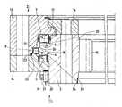
- the drawingshows a section through half of a center-free slewing bearing.
- the large roller bearing 1consists of an outer ring 2 and an inner ring 3, between which rolling elements 10, 11, 12 are arranged on raceways 4, 5, 6, 7, 8, 9.
- the large roller bearing 1is a three-row roller rotating connection in which the outer ring 2 is composed of two individual rings 13, 14.
- the inner ring 3is designed for rotary drive with a toothing 15.
- the inner ring 3is assigned a holding device 16 which engages over a collar 17 of the individual ring 13 in a form-fitting manner.
- the inner ring 3is provided with a nose 18 on which all three raceways 4, 6, 8 of the inner ring are arranged all around. Between this nose 18 and the outer ring 2, the support rollers 10, the radial rollers 11 and holding rollers 12 are arranged.
Landscapes
- Engineering & Computer Science (AREA)
- General Engineering & Computer Science (AREA)
- Mechanical Engineering (AREA)
- Physics & Mathematics (AREA)
- Analytical Chemistry (AREA)
- Health & Medical Sciences (AREA)
- Life Sciences & Earth Sciences (AREA)
- Chemical & Material Sciences (AREA)
- Acoustics & Sound (AREA)
- Biochemistry (AREA)
- General Health & Medical Sciences (AREA)
- General Physics & Mathematics (AREA)
- Immunology (AREA)
- Pathology (AREA)
- Rolling Contact Bearings (AREA)
- Investigating Or Analyzing Materials By The Use Of Ultrasonic Waves (AREA)
- Rolls And Other Rotary Bodies (AREA)
Abstract
Translated fromGermanDescription
Translated fromGermanDie Erfindung betrifft ein mittenfreies Großwälzlager nach dem Oberbegriff des Anspruchs 1.The invention relates to a center-free slewing bearing according to the preamble of claim 1.
Für verschiedene Einsatzfälle bei Großwälzlagern ist es sinnvoll, eine Ultraschallprüfvorrichtung vorzusehen, die es erlaubt, Materialfehler zerstörungsfrei festzustellen, ohne das Lager ausbauen zu müssen. Dieses betrifft insbesondere Großwälzlager als Drehverbindung für Krane im Offshorebetrieb.For various applications with large roller bearings, it makes sense to provide an ultrasonic test device that allows material defects to be determined without destruction, without having to remove the bearing. This applies in particular to large roller bearings as slewing rings for cranes in offshore operation.
Nach der EP A1 228 731 wird vorgeschlagen, in wenigstens einem Lagerring wenigstens eine Öffnung anzuordnen, in die eine Ultraschallsonde eingesetzt werden kann. Über eine Koppelfläche am anderen Lagerring sollen dann Materialfehler in diesem anderen Lagerring erkannt werden. Nachteilig bei dieser Ausbildung ist es erforderlich, daß die Ultraschallsonde im Bereich der Laufbahnen eingesetzt wird. Dadurch ist es erforderlich, in diesem Bereich mindestens teilweise das Schmierfett zu entfernen und zum Teil die Koppelfläche zu säubern. Abriebpartikel , die sich ebenfalls in diesem Bereich absondern, können darüber hinaus zu Fehlmessungen führen. Weiterhin ergibt sich bei längerer Betriebszeit des Lagers ei ne Erhöhung des Lagerspiels durch den zulässigen Verschleiß. Durch dieses erhöhte Lagerspiel verschiebt sich die Koppelfläche zur Lage der Ultraschallsonde, wodurch ebenfalls Fehlmessungen entstehen können.According to EP A1 228 731 it is proposed to arrange at least one opening in at least one bearing ring, into which an ultrasound probe can be inserted. Material defects in this other bearing ring are then to be identified via a coupling surface on the other bearing ring. A disadvantage of this design is that the ultrasound probe is used in the area of the raceways. As a result, it is necessary to at least partially remove the grease in this area and to partially clean the coupling surface. Abrasion particles that also separate in this area can also lead to incorrect measurements. Furthermore, if the bearing is in operation for a longer period of time, there is an increase in the bearing play due to the permissible wear. This increased bearing play shifts the coupling surface to the position of the ultrasound probe, which can also lead to incorrect measurements.
Der Erfindung liegt die Aufgabe zugrunde, die vorbeschriebenen Nachteile zu vermeiden und das Lager so auszubilden, daß eine einfache und sichere Ultraschallmessung möglich wird.The invention has for its object to avoid the disadvantages described above and to design the bearing so that a simple and safe ultrasonic measurement is possible.
Diese Aufgabe wird erfindungsgemäß durch die Merkmale des Anspruchs 1 gelöst.This object is achieved by the features of claim 1.
Vorteilhafte und zweckmäßige Ausbildungen werden in den Ansprüchen 2 bis 5 beschrieben.Advantageous and expedient training are described in claims 2 to 5.
Die Gestaltung eines Großwälzlagers nach der Erfindung ermögicht vorteilhaft eine einfache Anordnung von Ultraschallsonden. Es ist nicht mehr erforderlich, diese an unzugänglichen Stellen einzubringen, da die Koppelflächen für die Ankopplung der Ultraschallsonde umlaufend an den Außenflächen des zu prüfenden Lagerringes angeordnet sind. Weiterhin müssen für die Messungen keine besonderen Vorbereitungen mehr getroffen werden. Es ist lediglich die Korrosionsschutzschicht bzw. der Abdeckring oder ein Abdeckband von der Koppelfläche zu entfernen. Evtl. eingetretenes Lagerspiel, wie auch Abriebpartikel, die sich im Bereich der Laufbahnen ansammeln können, haben keine Auswirkung auf die Genauigkeit der Messung. Weiterhin ist in Verlängerung der Schallrichtung von Koppelfläche zum Untersuchungsbereich senkrecht zu dieser eine umlaufende Referenzfläche vorgesehen. Durch diese Maßnahme erhält man ein einwandfreies Rückwandecho und damit eine genaue Aussage über die Lage eines eventuellen Fehlers.The design of a large roller bearing according to the invention advantageously enables a simple arrangement of ultrasonic probes. It is no longer necessary to insert them in inaccessible places, since the coupling surfaces for coupling the ultrasound probe are arranged all around on the outer surfaces of the bearing ring to be tested. Furthermore, no special preparations have to be made for the measurements. It is only necessary to remove the corrosion protection layer or the cover ring or a cover strip from the coupling surface. Possibly. Bearing play that has occurred, as well as abrasion particles that can accumulate in the area of the raceways, have no effect on the accuracy of the measurement. In addition, a circumferential reference surface is provided to extend the sound direction from the coupling surface to the examination area perpendicular to this. This measure gives a perfect back wall echo and thus an exact statement about the location of a possible error.
Ein Ausführungsbeispiel der Erfindung ist in der Zeichnung dargestellt und wird im folgenden näher beschrieben. Die Zeichnung zeigt einen Schnitt durch eine Hälfte eines mittenfreien Großwälzlagers.An embodiment of the invention is shown in the drawing and will be described in more detail below. The drawing shows a section through half of a center-free slewing bearing.
Das Großwälzlager 1 besteht aus einem Außenring 2 und einem Innenring 3, zwischen denen auf Laufbahnen 4, 5, 6, 7, 8, 9 Wälzkörper 10, 11, 12 angeordnet sind. Im Ausführungsbeispiel handelt es sich bei dem Großwälzlager 1 um eine dreireihige Rollendrehverbindung, bei der der Außenring 2 aus zwei Einzelringen 13, 14 zusammengesetzt ist.The large roller bearing 1 consists of an outer ring 2 and an
Der Innenring 3 ist zum Drehantrieb mit einer Verzahnung 15 ausgebildet. Zum Katastrophenschutz ist dem Innenring 3 eine Haltevorrichtung 16 zugeordnet, die einen Kragen 17 des Einzelringes 13 formschlüssig übergreift. Der Innenring 3 ist mit einer Nase 18 versehen, an der umlaufend alle drei Laufbahnen 4, 6, 8 des Innenringes angeordnet sind. Zwischen dieser Nase 18 und dem Außenring 2 sind die Tragrollen 10, die Radialrollen 11 und Halterollen 12 angeordnet.The
Im Ausführungsbeispiel wird als rißgefährdeter Bereich im Ein zelring 14 des Außenringes 2 der Übergang zur Halterollenlaufbahn 5 angesehen. Im Innenring 3 werden als rißgefährdete Bereiche ebenfalls der Übergang zur Halterollenlaufbahn 4 sowie der Übergang zur Tragrollenlaufbahn 6 angesehen. Dementsprechend wird an der Außenfläche des Außenringes 2 eine Koppelfläche 19 angeordnet, an der eine Ultraschallsonde 20 angekoppelt werden kann. Diese Sonde wird über eine Haltevorrichtung 21 am Innenring 3 befestigt. Die Haltevorrichtung kann beispielsweise ein Magnetfuß sein. Die Ultraschallsonde 20 sendet die Prüfimpulse unter einem Winkel, so daß der gefährdete Bereich am Übergang zur Halterollenbahn 5 optimal erfaßt wird. In Verlängerung der Schallrichtung ist eine Referenzfläche 22 vorgesehen. Diese Referenzfläche 22 dient zur Kontrolle und Eichung der Ultraschallmessung. Im beschriebenen Ausführungsbeispiel wird hierzu eine ohnehin benötigte Fläche zur Aufnahme einer Dichtung 23 genutzt. In gleicher Weise sind am Innenring 3 zwei Koppelflächen 24, 25 angeordnet. Wie in der Zeichnung dargestellt, ist es denkbar, daß die Ultraschallsonde 20 die Prüfimpulse unter einem beliebigen Winkel zur Koppelfläche 25, 24 sendet oder auch, wie zur Koppelfläche 25 senkrecht. An der Koppelfläche 24 ist ein Abdeckband 28 dargestellt. Die Referenzflächen 26, 27 sind im Ausführungsbeispiel am Außendurchmesser der Nase anschließend an die Radialrollenlaufbahn 8 angeordnet.
- 1 Großwälzlager
- 2 Außenring
- 3 Innenring
- 4 Halterollenlaufbahn
- 5 Halterollenlaufbahn
- 6 Tragrollenlaufbahn
- 7 Tragrollenlaufbahn
- 8 Radialrollenlaufbahn
- 9 Radialrollenlaufbahn
- 10 Tragrollen
- 11 Radialrollen
- 12 Halterollen
- 13 Einzelring
- 14 Einzelring
- 15 Verzahnung
- 16 Haltevorrichtung
- 17 Kragen
- 18 Nase
- 19 Koppelfläche
- 20 Ultraschallsonde
- 21 Haltevorrichtung
- 22 Referenzfläche
- 23 Dichtung
- 24 Koppelfläche
- 25 Koppelfläche
- 26 Referenzfläche
- 27 Referenzfläche
- 28 Abdeckband
- 1 slewing bearing
- 2 outer ring
- 3 inner ring
- 4 holding roller track
- 5 holding roller track
- 6 idler track
- 7 idler track
- 8 radial roller raceway
- 9 radial roller raceway
- 10 idlers
- 11 radial rollers
- 12 holding rollers
- 13 single ring
- 14 single ring
- 15 gearing
- 16 holding device
- 17 collar
- 18 nose
- 19 coupling surface
- 20 ultrasound probe
- 21 holding device
- 22 reference surface
- 23 seal
- 24 coupling surface
- 25 coupling surface
- 26 reference surface
- 27 reference surface
- 28 masking tape
Claims (5)
Translated fromGermanApplications Claiming Priority (2)
| Application Number | Priority Date | Filing Date | Title |
|---|---|---|---|
| DE19893927077DE3927077A1 (en) | 1989-08-17 | 1989-08-17 | MEDIUM-FREE WHOLE BEARING |
| DE3927077 | 1989-08-17 |
Publications (3)
| Publication Number | Publication Date |
|---|---|
| EP0413119A2true EP0413119A2 (en) | 1991-02-20 |
| EP0413119A3 EP0413119A3 (en) | 1992-02-26 |
| EP0413119B1 EP0413119B1 (en) | 1993-05-12 |
Family
ID=6387244
Family Applications (1)
| Application Number | Title | Priority Date | Filing Date |
|---|---|---|---|
| EP19900112660Expired - LifetimeEP0413119B1 (en) | 1989-08-17 | 1990-07-03 | Center open large rolling bearing |
Country Status (8)
| Country | Link |
|---|---|
| US (1) | US5074677A (en) |
| EP (1) | EP0413119B1 (en) |
| JP (1) | JPH0747970B2 (en) |
| AU (1) | AU633130B2 (en) |
| DE (2) | DE3927077A1 (en) |
| ES (1) | ES2020497T3 (en) |
| LU (1) | LU87937A1 (en) |
| NO (1) | NO300106B1 (en) |
Cited By (15)
| Publication number | Priority date | Publication date | Assignee | Title |
|---|---|---|---|---|
| EP0529354A1 (en)* | 1991-08-30 | 1993-03-03 | Fried. Krupp AG Hoesch-Krupp | Device for monitoring rolling contact bearings |
| EP0759545A1 (en)* | 1995-08-22 | 1997-02-26 | The Torrington Company | Bearing with sensor |
| EP0759544A1 (en)* | 1995-08-22 | 1997-02-26 | The Torrington Company | Bearing with temperature sensor |
| WO1999031500A1 (en)* | 1997-01-24 | 1999-06-24 | Skf Engineering & Research Centre B.V. | Ultrasonic in-situ inspection for slewing bearings |
| DE19919006C2 (en)* | 1999-04-27 | 2003-08-14 | Fag Kugelfischer Ag & Co Kg | Device for measuring warehouse data |
| WO2008058729A1 (en) | 2006-11-16 | 2008-05-22 | Rothe Erde Gmbh | Rolling bearing, in particular centreless large rolling bearing |
| WO2008064805A1 (en) | 2006-11-27 | 2008-06-05 | Rothe Erde Gmbh | Roller bearing, particularly slewing ring bearing with no center |
| EP1775492A4 (en)* | 2004-05-17 | 2009-06-17 | Jtekt Corp | Shaft joint monitoring device |
| CN104968953A (en)* | 2013-01-23 | 2015-10-07 | 蒂森克虏伯罗特艾德有限公司 | Cylindrical Roller Bearings |
| DE102015112056A1 (en) | 2015-07-23 | 2017-01-26 | Thyssenkrupp Ag | Rolling bearing assembly, in particular large rolling bearing assembly, and blade bearing for a wind turbine |
| EP3339853A1 (en) | 2016-12-22 | 2018-06-27 | Nordex Energy GmbH | Method for acoustically examining a path of travel of a main body of a large scale roller bearing |
| US20190323553A1 (en)* | 2018-04-20 | 2019-10-24 | Aktiebolaget Skf | Roller bearing for supporting radial deformation of the roller bearing, and rotative assembly comprising such roller bearing |
| WO2020025094A1 (en)* | 2018-08-02 | 2020-02-06 | Vestas Wind Systems A/S | Pitch bearing |
| WO2020187874A1 (en)* | 2019-03-21 | 2020-09-24 | Liebherr-Components Biberach Gmbh | Seal for large rolling bearing |
| LU502800B1 (en) | 2022-09-15 | 2024-03-15 | Luxembourg Inst Science & Tech List | Wear sensing and wear sensor |
Families Citing this family (26)
| Publication number | Priority date | Publication date | Assignee | Title |
|---|---|---|---|---|
| US5408884A (en)* | 1993-12-06 | 1995-04-25 | Electric Power Research Institute, Inc. | Apparatus and method for ultrasonic reconstruction and testing of a turbine rotor blade attachment structure |
| DE19511430A1 (en)* | 1995-03-29 | 1996-10-02 | Leybold Ag | Circulation blower, vacuum pump or the like |
| NL1005088C2 (en)* | 1997-01-24 | 1998-07-27 | Skf Ind Trading & Dev | Single row bearing and monitoring device. |
| US9062710B2 (en)* | 2013-02-05 | 2015-06-23 | Schaeffler Technologies AG & Co. KG | Combined load rolling bearing |
| ATE426116T1 (en)* | 2005-09-01 | 2009-04-15 | Imo Momentenlager Gmbh | WIND TURBINE WITH ELEMENT FOR SEALING TWO ROTATABLE PARTS AGAINST EACH OTHER |
| DE102005053335B4 (en)* | 2005-11-07 | 2007-09-20 | Rothe Erde Gmbh | Method for measuring the wear on the running surfaces of seal races and wear measuring device for carrying out the method |
| DE202007002609U1 (en)* | 2007-02-19 | 2008-04-03 | Landwehr, Markus | rotary joint |
| DE102007020938B8 (en)* | 2007-05-04 | 2009-04-23 | Rothe Erde Gmbh | Device for detecting and monitoring damage to rolling bearings |
| RU2340544C1 (en)* | 2007-06-22 | 2008-12-10 | Закрытое акционерное общество "Инженерно-технический центр "КРОС" | Steering gear |
| US8002472B2 (en) | 2008-06-30 | 2011-08-23 | Nucor Corporation | Slew bearing system |
| DE102008050620A1 (en)* | 2008-10-09 | 2010-04-15 | Imo Holding Gmbh | Device for rotatable coupling of two coaxial connection elements |
| DE102009022206B3 (en)* | 2009-05-20 | 2010-12-02 | Schaeffler Technologies Gmbh & Co. Kg | Bearing for machine tools, has braking or clamping device, bearing ring connected to two bearing units, where clamping element is held at latter bearing unit |
| EP3940190B1 (en)* | 2009-05-25 | 2023-09-27 | Aktiebolaget SKF | Bearing arrangement for a drilling assembly |
| CN101649862B (en)* | 2009-09-21 | 2011-05-18 | 洛阳世必爱特种轴承有限公司 | Three-row roller turntable bearing for heavy-duty machinery |
| CN101700857B (en) | 2009-09-30 | 2012-01-25 | 马鞍山方圆回转支承股份有限公司 | Heavy-load large-size pivoting support |
| DE102011005921A1 (en)* | 2010-12-07 | 2012-06-14 | Aktiebolaget Skf | Friction-increasing paint and thus coated machine part |
| CN102072259A (en)* | 2011-01-24 | 2011-05-25 | 南京工大数控科技有限公司 | Intelligent slewing bearing with implanted sensors |
| FR2973087B1 (en)* | 2011-03-25 | 2014-04-18 | Defontaine | BEARING HAS THREE ROWS AND MORE ROLLING BODIES |
| DE202011110128U1 (en) | 2011-04-05 | 2012-12-19 | Imo Holding Gmbh | Slewing connection for underwater operation |
| FR2996888B1 (en)* | 2012-10-12 | 2015-06-19 | Skf Ab | BEARING BEARING HAS AT LEAST TWO ROWS OF ROLLING ELEMENTS, IN PARTICULAR FOR TUNNELIER |
| DE102017207814A1 (en)* | 2016-06-06 | 2017-12-07 | Aktiebolaget Skf | Swivel bearing with seal arrangement |
| DE102017128949A1 (en) | 2017-12-06 | 2019-06-06 | Thyssenkrupp Ag | Rolling bearing assembly and method |
| DE202019101697U1 (en)* | 2019-03-26 | 2020-07-02 | Liebherr-Components Biberach Gmbh | Slewing bearings |
| DE102019003330A1 (en)* | 2019-05-10 | 2020-11-12 | Imo Holding Gmbh | Rolling bearing arrangement, in particular for a wind turbine |
| DE102019216422A1 (en)* | 2019-10-24 | 2021-04-29 | Aktiebolaget Skf | Rolling bearings with an ultrasonic distance sensor |
| DE102020103421A1 (en)* | 2020-02-11 | 2021-08-12 | Liebherr-Components Biberach Gmbh | Rolling bearing with monitoring device |
Family Cites Families (10)
| Publication number | Priority date | Publication date | Assignee | Title |
|---|---|---|---|---|
| DE952045C (en)* | 1954-10-23 | 1956-11-08 | Rothe Erde Eisenwerk | Three-part two-row ball and socket assembly, especially for the backlash-free storage of upper parts of rotating hoists |
| DD17558A1 (en)* | 1957-08-21 | 1959-10-13 | Slewing ring for cranes, excavators and other rotary and swivel equipment | |
| DD31203A2 (en)* | 1957-08-21 | 1964-09-05 | Slewing ring for cranes, excavators and other rotary and swivel equipment | |
| GB1254409A (en)* | 1969-11-28 | 1971-11-24 | Hoesch Ag | Improvements in or relating to rotary roller bearings |
| US3969926A (en)* | 1975-03-27 | 1976-07-20 | Krautkramer-Branson, Incorporated | Alignment of ultrasonic transducer probe in pulse-echo testing |
| GB1572107A (en)* | 1977-12-14 | 1980-07-23 | British Steel Corp | Ultrasonic testing of long objects |
| NL8503517A (en)* | 1985-12-19 | 1987-07-16 | Skf Ind Trading & Dev | SWING CIRCLE. |
| US4865468A (en)* | 1988-05-27 | 1989-09-12 | Ntn Toyo Bearing Co., Ltd. | Wheel bearing assembly for automotive wheel |
| DE3725027A1 (en)* | 1987-07-29 | 1989-02-09 | Hoesch Ag | WIRE ROLLER BEARING WITH FLAT WIRE |
| DE3942847A1 (en)* | 1989-03-23 | 1991-06-27 | Hoesch Ag | CENTER-FREE ROLL TURN JOINT |
- 1989
- 1989-08-17DEDE19893927077patent/DE3927077A1/ennot_activeWithdrawn
- 1990
- 1990-07-03DEDE9090112660Tpatent/DE59001424D1/ennot_activeExpired - Fee Related
- 1990-07-03EPEP19900112660patent/EP0413119B1/ennot_activeExpired - Lifetime
- 1990-07-03ESES90112660Tpatent/ES2020497T3/ennot_activeExpired - Lifetime
- 1990-08-02NONO903404Apatent/NO300106B1/enunknown
- 1990-08-16USUS07/568,404patent/US5074677A/ennot_activeExpired - Lifetime
- 1990-08-16AUAU61059/90Apatent/AU633130B2/ennot_activeCeased
- 1990-08-17JPJP21596590Apatent/JPH0747970B2/ennot_activeExpired - Fee Related
- 1991
- 1991-05-14LULU87937Apatent/LU87937A1/enunknown
Cited By (22)
| Publication number | Priority date | Publication date | Assignee | Title |
|---|---|---|---|---|
| EP0529354A1 (en)* | 1991-08-30 | 1993-03-03 | Fried. Krupp AG Hoesch-Krupp | Device for monitoring rolling contact bearings |
| AU643152B2 (en)* | 1991-08-30 | 1993-11-04 | Fried. Krupp Ag Hoesch-Krupp | Device for monitoring roller bearings |
| EP0759545A1 (en)* | 1995-08-22 | 1997-02-26 | The Torrington Company | Bearing with sensor |
| EP0759544A1 (en)* | 1995-08-22 | 1997-02-26 | The Torrington Company | Bearing with temperature sensor |
| US5805080A (en)* | 1995-08-22 | 1998-09-08 | The Torrington Company | Bearing with an electric-acoustic transducer for transmitting information regarding various parameters within the bearing |
| WO1999031500A1 (en)* | 1997-01-24 | 1999-06-24 | Skf Engineering & Research Centre B.V. | Ultrasonic in-situ inspection for slewing bearings |
| DE19919006C2 (en)* | 1999-04-27 | 2003-08-14 | Fag Kugelfischer Ag & Co Kg | Device for measuring warehouse data |
| EP1775492A4 (en)* | 2004-05-17 | 2009-06-17 | Jtekt Corp | Shaft joint monitoring device |
| WO2008058729A1 (en) | 2006-11-16 | 2008-05-22 | Rothe Erde Gmbh | Rolling bearing, in particular centreless large rolling bearing |
| WO2008064805A1 (en) | 2006-11-27 | 2008-06-05 | Rothe Erde Gmbh | Roller bearing, particularly slewing ring bearing with no center |
| CN104968953A (en)* | 2013-01-23 | 2015-10-07 | 蒂森克虏伯罗特艾德有限公司 | Cylindrical Roller Bearings |
| DE102015112056A1 (en) | 2015-07-23 | 2017-01-26 | Thyssenkrupp Ag | Rolling bearing assembly, in particular large rolling bearing assembly, and blade bearing for a wind turbine |
| DE102015112056B4 (en) | 2015-07-23 | 2024-09-05 | Thyssenkrupp Ag | Rolling bearing arrangement, in particular large rolling bearing arrangement, and blade bearing for a wind turbine |
| EP3339853A1 (en) | 2016-12-22 | 2018-06-27 | Nordex Energy GmbH | Method for acoustically examining a path of travel of a main body of a large scale roller bearing |
| US20190323553A1 (en)* | 2018-04-20 | 2019-10-24 | Aktiebolaget Skf | Roller bearing for supporting radial deformation of the roller bearing, and rotative assembly comprising such roller bearing |
| US10683890B2 (en)* | 2018-04-20 | 2020-06-16 | Aktiebolaget Skf | Roller bearing for supporting radial deformation of the roller bearing and rotative assembly comprising such roller bearing |
| WO2020025094A1 (en)* | 2018-08-02 | 2020-02-06 | Vestas Wind Systems A/S | Pitch bearing |
| WO2020187874A1 (en)* | 2019-03-21 | 2020-09-24 | Liebherr-Components Biberach Gmbh | Seal for large rolling bearing |
| CN113677904A (en)* | 2019-03-21 | 2021-11-19 | 利勃海尔比伯拉赫零部件有限公司 | Seal for large roller bearing |
| CN113677904B (en)* | 2019-03-21 | 2023-11-17 | 利勃海尔比伯拉赫零部件有限公司 | Seal for large roller bearings |
| US11933360B2 (en) | 2019-03-21 | 2024-03-19 | Liebherr-Components Biberach Gmbh | Seal for large roller bearing |
| LU502800B1 (en) | 2022-09-15 | 2024-03-15 | Luxembourg Inst Science & Tech List | Wear sensing and wear sensor |
Also Published As
| Publication number | Publication date |
|---|---|
| JPH0747970B2 (en) | 1995-05-24 |
| DE3927077A1 (en) | 1991-02-21 |
| NO903404L (en) | 1991-02-18 |
| DE59001424D1 (en) | 1993-06-17 |
| EP0413119A3 (en) | 1992-02-26 |
| EP0413119B1 (en) | 1993-05-12 |
| NO903404D0 (en) | 1990-08-02 |
| AU6105990A (en) | 1991-02-21 |
| ES2020497T3 (en) | 1993-10-16 |
| ES2020497A4 (en) | 1991-08-16 |
| JPH03181613A (en) | 1991-08-07 |
| LU87937A1 (en) | 1992-03-03 |
| US5074677A (en) | 1991-12-24 |
| AU633130B2 (en) | 1993-01-21 |
| NO300106B1 (en) | 1997-04-07 |
Similar Documents
| Publication | Publication Date | Title |
|---|---|---|
| EP0413119B1 (en) | Center open large rolling bearing | |
| DE2746937C2 (en) | Force measuring device | |
| EP0349821B1 (en) | Device for web tension measuring | |
| AT398235B (en) | DEVICE FOR THE SEALING PERFORMANCE OF SHAFTS WITH A LARGE ROTATIONAL ERROR BY CONNECTING PIPES OF CLOSED CONTAINERS | |
| EP1528356B1 (en) | Apparatus for monitoring of large roller bearings | |
| DE69825843T2 (en) | Device for measuring the axial thrust in a rotating shaft | |
| DE2360188C2 (en) | Rotation lock on bearings for the rolls of roll stands | |
| DE8413413U1 (en) | Balancing machine for wheels with pneumatic tires | |
| DE3111434C2 (en) | Device for measuring the axial force in a shaft supported by roller bearings | |
| WO2007028575A1 (en) | Sensor arrangement | |
| DE19640895B4 (en) | Rolling bearing with an integrated speed measuring device | |
| DE2636246A1 (en) | METHOD AND DEVICE FOR ULTRASONIC TESTING OF THE CONNECTOR FIELDS OF A REACTOR PRESSURE VESSEL | |
| DE102019218884A1 (en) | Slewing bearings | |
| DE3623976A1 (en) | Device for measuring the radial play of antifriction (rolling) bearings | |
| DE2219466B2 (en) | Roll holder for universal roll stands | |
| DE3248644C1 (en) | Plain bearings for structures in civil engineering | |
| DE3739190A1 (en) | ROTOR HEAD TO SCAN THE SURFACE OF CYLINDRICAL TEST PARTS | |
| DE3104097A1 (en) | Live ring | |
| DE2636107C3 (en) | Ultrasonic probe for the inspection of hollow cylindrical grains from their inner circumference, especially for hollow bored screws of reactor pressure vessels | |
| DE19753583C2 (en) | Device for measuring the speed of rolling bearings | |
| DE3504522C2 (en) | Method and device for ultrasonic testing of screws for incipient cracks | |
| DE19922474C2 (en) | Centering aid for welding flanges into pipes | |
| DE2121246C3 (en) | Flatness measuring device | |
| DE2004628B2 (en) | DRIVE DEVICE FOR ROTATING BODIES TO BE TESTED IN A NON-DESTRUCTION-FREE TESTING DEVICE | |
| DE2103637B2 (en) | Ball surface scanner with rotary drive - has bearing and holding element for ball with rotation symmetrical recess |
Legal Events
| Date | Code | Title | Description |
|---|---|---|---|
| PUAI | Public reference made under article 153(3) epc to a published international application that has entered the european phase | Free format text:ORIGINAL CODE: 0009012 | |
| AK | Designated contracting states | Kind code of ref document:A2 Designated state(s):BE CH DE ES FR GB IT LI NL | |
| GBC | Gb: translation of claims filed (gb section 78(7)/1977) | ||
| ITCL | It: translation for ep claims filed | Representative=s name:RICCARDI SERGIO & CO. | |
| TCNL | Nl: translation of patent claims filed | ||
| EL | Fr: translation of claims filed | ||
| PUAL | Search report despatched | Free format text:ORIGINAL CODE: 0009013 | |
| AK | Designated contracting states | Kind code of ref document:A3 Designated state(s):BE CH DE ES FR GB IT LI NL | |
| 17P | Request for examination filed | Effective date:19920122 | |
| 17Q | First examination report despatched | Effective date:19920630 | |
| RAP1 | Party data changed (applicant data changed or rights of an application transferred) | Owner name:FRIED. KRUPP AG HOESCH-KRUPP | |
| GRAA | (expected) grant | Free format text:ORIGINAL CODE: 0009210 | |
| AK | Designated contracting states | Kind code of ref document:B1 Designated state(s):BE CH DE ES FR GB IT LI NL | |
| REF | Corresponds to: | Ref document number:59001424 Country of ref document:DE Date of ref document:19930617 | |
| GBT | Gb: translation of ep patent filed (gb section 77(6)(a)/1977) | Effective date:19930525 | |
| ET | Fr: translation filed | ||
| ITF | It: translation for a ep patent filed | ||
| REG | Reference to a national code | Ref country code:ES Ref legal event code:FG2A Ref document number:2020497 Country of ref document:ES Kind code of ref document:T3 | |
| REG | Reference to a national code | Ref country code:GB Ref legal event code:IF02 | |
| PGFP | Annual fee paid to national office [announced via postgrant information from national office to epo] | Ref country code:GB Payment date:20050621 Year of fee payment:16 | |
| PGFP | Annual fee paid to national office [announced via postgrant information from national office to epo] | Ref country code:FR Payment date:20050712 Year of fee payment:16 | |
| PGFP | Annual fee paid to national office [announced via postgrant information from national office to epo] | Ref country code:NL Payment date:20050714 Year of fee payment:16 Ref country code:DE Payment date:20050714 Year of fee payment:16 Ref country code:CH Payment date:20050714 Year of fee payment:16 | |
| PGFP | Annual fee paid to national office [announced via postgrant information from national office to epo] | Ref country code:ES Payment date:20050719 Year of fee payment:16 | |
| PGFP | Annual fee paid to national office [announced via postgrant information from national office to epo] | Ref country code:BE Payment date:20050801 Year of fee payment:16 | |
| PG25 | Lapsed in a contracting state [announced via postgrant information from national office to epo] | Ref country code:GB Free format text:LAPSE BECAUSE OF NON-PAYMENT OF DUE FEES Effective date:20060703 | |
| PG25 | Lapsed in a contracting state [announced via postgrant information from national office to epo] | Ref country code:LI Free format text:LAPSE BECAUSE OF NON-PAYMENT OF DUE FEES Effective date:20060731 Ref country code:CH Free format text:LAPSE BECAUSE OF NON-PAYMENT OF DUE FEES Effective date:20060731 Ref country code:BE Free format text:LAPSE BECAUSE OF NON-PAYMENT OF DUE FEES Effective date:20060731 | |
| PGFP | Annual fee paid to national office [announced via postgrant information from national office to epo] | Ref country code:IT Payment date:20060731 Year of fee payment:17 | |
| PG25 | Lapsed in a contracting state [announced via postgrant information from national office to epo] | Ref country code:NL Free format text:LAPSE BECAUSE OF NON-PAYMENT OF DUE FEES Effective date:20070201 Ref country code:DE Free format text:LAPSE BECAUSE OF NON-PAYMENT OF DUE FEES Effective date:20070201 | |
| REG | Reference to a national code | Ref country code:CH Ref legal event code:PL | |
| GBPC | Gb: european patent ceased through non-payment of renewal fee | Effective date:20060703 | |
| NLV4 | Nl: lapsed or anulled due to non-payment of the annual fee | Effective date:20070201 | |
| REG | Reference to a national code | Ref country code:FR Ref legal event code:ST Effective date:20070330 | |
| REG | Reference to a national code | Ref country code:ES Ref legal event code:FD2A Effective date:20060704 | |
| BERE | Be: lapsed | Owner name:FRIED. *KRUPP A.G. HOESCH-KRUPP Effective date:20060731 | |
| PG25 | Lapsed in a contracting state [announced via postgrant information from national office to epo] | Ref country code:ES Free format text:LAPSE BECAUSE OF NON-PAYMENT OF DUE FEES Effective date:20060704 | |
| PG25 | Lapsed in a contracting state [announced via postgrant information from national office to epo] | Ref country code:FR Free format text:LAPSE BECAUSE OF NON-PAYMENT OF DUE FEES Effective date:20060731 | |
| PG25 | Lapsed in a contracting state [announced via postgrant information from national office to epo] | Ref country code:IT Free format text:LAPSE BECAUSE OF NON-PAYMENT OF DUE FEES Effective date:20070703 | |
| PLBE | No opposition filed within time limit | Free format text:ORIGINAL CODE: 0009261 | |
| STAA | Information on the status of an ep patent application or granted ep patent | Free format text:STATUS: NO OPPOSITION FILED WITHIN TIME LIMIT |