EP0404716A1 - Anchored shaft for a femoral prosthesis - Google Patents
Anchored shaft for a femoral prosthesisDownload PDFInfo
- Publication number
- EP0404716A1 EP0404716A1EP90810336AEP90810336AEP0404716A1EP 0404716 A1EP0404716 A1EP 0404716A1EP 90810336 AEP90810336 AEP 90810336AEP 90810336 AEP90810336 AEP 90810336AEP 0404716 A1EP0404716 A1EP 0404716A1
- Authority
- EP
- European Patent Office
- Prior art keywords
- shaft
- collar
- recess
- prosthesis
- bone
- Prior art date
- Legal status (The legal status is an assumption and is not a legal conclusion. Google has not performed a legal analysis and makes no representation as to the accuracy of the status listed.)
- Granted
Links
- 210000000988bone and boneAnatomy0.000claimsabstractdescription18
- 238000004873anchoringMethods0.000claimsabstractdescription8
- 239000000945fillerSubstances0.000claimsabstractdescription8
- 210000000689upper legAnatomy0.000claimsdescription6
- 241000309551Arthraxon hispidusSpecies0.000claimsdescription5
- 229920002635polyurethanePolymers0.000claimsdescription3
- 239000004814polyurethaneSubstances0.000claimsdescription3
- 229920001971elastomerPolymers0.000claimsdescription2
- 239000000806elastomerSubstances0.000claimsdescription2
- 229920001296polysiloxanePolymers0.000claimsdescription2
- 230000001054cortical effectEffects0.000abstractdescription6
- 238000010276constructionMethods0.000abstractdescription2
- 238000002271resectionMethods0.000abstractdescription2
- 239000000463materialSubstances0.000description2
- 238000012856packingMethods0.000description2
- 210000001519tissueAnatomy0.000description2
- 229910001069Ti alloyInorganic materials0.000description1
- 230000005540biological transmissionEffects0.000description1
- 230000015556catabolic processEffects0.000description1
- 239000011248coating agentSubstances0.000description1
- 238000000576coating methodMethods0.000description1
- 230000012010growthEffects0.000description1
- 229910052588hydroxylapatiteInorganic materials0.000description1
- 238000002513implantationMethods0.000description1
- 229910052751metalInorganic materials0.000description1
- 239000002184metalSubstances0.000description1
- XYJRXVWERLGGKC-UHFFFAOYSA-Dpentacalcium;hydroxide;triphosphateChemical compound[OH-].[Ca+2].[Ca+2].[Ca+2].[Ca+2].[Ca+2].[O-]P([O-])([O-])=O.[O-]P([O-])([O-])=O.[O-]P([O-])([O-])=OXYJRXVWERLGGKC-UHFFFAOYSA-D0.000description1
- 230000008467tissue growthEffects0.000description1
Images
Classifications
- A—HUMAN NECESSITIES
- A61—MEDICAL OR VETERINARY SCIENCE; HYGIENE
- A61F—FILTERS IMPLANTABLE INTO BLOOD VESSELS; PROSTHESES; DEVICES PROVIDING PATENCY TO, OR PREVENTING COLLAPSING OF, TUBULAR STRUCTURES OF THE BODY, e.g. STENTS; ORTHOPAEDIC, NURSING OR CONTRACEPTIVE DEVICES; FOMENTATION; TREATMENT OR PROTECTION OF EYES OR EARS; BANDAGES, DRESSINGS OR ABSORBENT PADS; FIRST-AID KITS
- A61F2/00—Filters implantable into blood vessels; Prostheses, i.e. artificial substitutes or replacements for parts of the body; Appliances for connecting them with the body; Devices providing patency to, or preventing collapsing of, tubular structures of the body, e.g. stents
- A61F2/02—Prostheses implantable into the body
- A61F2/30—Joints
- A61F2/32—Joints for the hip
- A61F2/36—Femoral heads ; Femoral endoprostheses
- A61F2/3662—Femoral shafts
- A61F2/367—Proximal or metaphyseal parts of shafts
- A—HUMAN NECESSITIES
- A61—MEDICAL OR VETERINARY SCIENCE; HYGIENE
- A61F—FILTERS IMPLANTABLE INTO BLOOD VESSELS; PROSTHESES; DEVICES PROVIDING PATENCY TO, OR PREVENTING COLLAPSING OF, TUBULAR STRUCTURES OF THE BODY, e.g. STENTS; ORTHOPAEDIC, NURSING OR CONTRACEPTIVE DEVICES; FOMENTATION; TREATMENT OR PROTECTION OF EYES OR EARS; BANDAGES, DRESSINGS OR ABSORBENT PADS; FIRST-AID KITS
- A61F2/00—Filters implantable into blood vessels; Prostheses, i.e. artificial substitutes or replacements for parts of the body; Appliances for connecting them with the body; Devices providing patency to, or preventing collapsing of, tubular structures of the body, e.g. stents
- A61F2/02—Prostheses implantable into the body
- A61F2/30—Joints
- A61F2002/30001—Additional features of subject-matter classified in A61F2/28, A61F2/30 and subgroups thereof
- A61F2002/30003—Material related properties of the prosthesis or of a coating on the prosthesis
- A61F2002/30004—Material related properties of the prosthesis or of a coating on the prosthesis the prosthesis being made from materials having different values of a given property at different locations within the same prosthesis
- A61F2002/30014—Material related properties of the prosthesis or of a coating on the prosthesis the prosthesis being made from materials having different values of a given property at different locations within the same prosthesis differing in elasticity, stiffness or compressibility
- A—HUMAN NECESSITIES
- A61—MEDICAL OR VETERINARY SCIENCE; HYGIENE
- A61F—FILTERS IMPLANTABLE INTO BLOOD VESSELS; PROSTHESES; DEVICES PROVIDING PATENCY TO, OR PREVENTING COLLAPSING OF, TUBULAR STRUCTURES OF THE BODY, e.g. STENTS; ORTHOPAEDIC, NURSING OR CONTRACEPTIVE DEVICES; FOMENTATION; TREATMENT OR PROTECTION OF EYES OR EARS; BANDAGES, DRESSINGS OR ABSORBENT PADS; FIRST-AID KITS
- A61F2/00—Filters implantable into blood vessels; Prostheses, i.e. artificial substitutes or replacements for parts of the body; Appliances for connecting them with the body; Devices providing patency to, or preventing collapsing of, tubular structures of the body, e.g. stents
- A61F2/02—Prostheses implantable into the body
- A61F2/30—Joints
- A61F2002/30001—Additional features of subject-matter classified in A61F2/28, A61F2/30 and subgroups thereof
- A61F2002/30316—The prosthesis having different structural features at different locations within the same prosthesis; Connections between prosthetic parts; Special structural features of bone or joint prostheses not otherwise provided for
- A61F2002/30535—Special structural features of bone or joint prostheses not otherwise provided for
- A61F2002/30563—Special structural features of bone or joint prostheses not otherwise provided for having elastic means or damping means, different from springs, e.g. including an elastomeric core or shock absorbers
- A—HUMAN NECESSITIES
- A61—MEDICAL OR VETERINARY SCIENCE; HYGIENE
- A61F—FILTERS IMPLANTABLE INTO BLOOD VESSELS; PROSTHESES; DEVICES PROVIDING PATENCY TO, OR PREVENTING COLLAPSING OF, TUBULAR STRUCTURES OF THE BODY, e.g. STENTS; ORTHOPAEDIC, NURSING OR CONTRACEPTIVE DEVICES; FOMENTATION; TREATMENT OR PROTECTION OF EYES OR EARS; BANDAGES, DRESSINGS OR ABSORBENT PADS; FIRST-AID KITS
- A61F2/00—Filters implantable into blood vessels; Prostheses, i.e. artificial substitutes or replacements for parts of the body; Appliances for connecting them with the body; Devices providing patency to, or preventing collapsing of, tubular structures of the body, e.g. stents
- A61F2/02—Prostheses implantable into the body
- A61F2/30—Joints
- A61F2/30721—Accessories
- A61F2002/30733—Inserts placed into an endoprosthetic cavity, e.g. for modifying a material property
- A—HUMAN NECESSITIES
- A61—MEDICAL OR VETERINARY SCIENCE; HYGIENE
- A61F—FILTERS IMPLANTABLE INTO BLOOD VESSELS; PROSTHESES; DEVICES PROVIDING PATENCY TO, OR PREVENTING COLLAPSING OF, TUBULAR STRUCTURES OF THE BODY, e.g. STENTS; ORTHOPAEDIC, NURSING OR CONTRACEPTIVE DEVICES; FOMENTATION; TREATMENT OR PROTECTION OF EYES OR EARS; BANDAGES, DRESSINGS OR ABSORBENT PADS; FIRST-AID KITS
- A61F2/00—Filters implantable into blood vessels; Prostheses, i.e. artificial substitutes or replacements for parts of the body; Appliances for connecting them with the body; Devices providing patency to, or preventing collapsing of, tubular structures of the body, e.g. stents
- A61F2/02—Prostheses implantable into the body
- A61F2/30—Joints
- A61F2/32—Joints for the hip
- A61F2/36—Femoral heads ; Femoral endoprostheses
- A61F2/3609—Femoral heads or necks; Connections of endoprosthetic heads or necks to endoprosthetic femoral shafts
- A61F2002/3625—Necks
- A61F2002/3631—Necks with an integral complete or partial peripheral collar or bearing shoulder at its base
- A—HUMAN NECESSITIES
- A61—MEDICAL OR VETERINARY SCIENCE; HYGIENE
- A61F—FILTERS IMPLANTABLE INTO BLOOD VESSELS; PROSTHESES; DEVICES PROVIDING PATENCY TO, OR PREVENTING COLLAPSING OF, TUBULAR STRUCTURES OF THE BODY, e.g. STENTS; ORTHOPAEDIC, NURSING OR CONTRACEPTIVE DEVICES; FOMENTATION; TREATMENT OR PROTECTION OF EYES OR EARS; BANDAGES, DRESSINGS OR ABSORBENT PADS; FIRST-AID KITS
- A61F2/00—Filters implantable into blood vessels; Prostheses, i.e. artificial substitutes or replacements for parts of the body; Appliances for connecting them with the body; Devices providing patency to, or preventing collapsing of, tubular structures of the body, e.g. stents
- A61F2/02—Prostheses implantable into the body
- A61F2/30—Joints
- A61F2/32—Joints for the hip
- A61F2/36—Femoral heads ; Femoral endoprostheses
- A61F2/3662—Femoral shafts
- A61F2002/3678—Geometrical features
- A61F2002/368—Geometrical features with lateral apertures, bores, holes or openings, e.g. for reducing the mass, for receiving fixation screws or for communicating with the inside of a hollow shaft
- A—HUMAN NECESSITIES
- A61—MEDICAL OR VETERINARY SCIENCE; HYGIENE
- A61F—FILTERS IMPLANTABLE INTO BLOOD VESSELS; PROSTHESES; DEVICES PROVIDING PATENCY TO, OR PREVENTING COLLAPSING OF, TUBULAR STRUCTURES OF THE BODY, e.g. STENTS; ORTHOPAEDIC, NURSING OR CONTRACEPTIVE DEVICES; FOMENTATION; TREATMENT OR PROTECTION OF EYES OR EARS; BANDAGES, DRESSINGS OR ABSORBENT PADS; FIRST-AID KITS
- A61F2250/00—Special features of prostheses classified in groups A61F2/00 - A61F2/26 or A61F2/82 or A61F9/00 or A61F11/00 or subgroups thereof
- A61F2250/0014—Special features of prostheses classified in groups A61F2/00 - A61F2/26 or A61F2/82 or A61F9/00 or A61F11/00 or subgroups thereof having different values of a given property or geometrical feature, e.g. mechanical property or material property, at different locations within the same prosthesis
- A61F2250/0018—Special features of prostheses classified in groups A61F2/00 - A61F2/26 or A61F2/82 or A61F9/00 or A61F11/00 or subgroups thereof having different values of a given property or geometrical feature, e.g. mechanical property or material property, at different locations within the same prosthesis differing in elasticity, stiffness or compressibility
- A—HUMAN NECESSITIES
- A61—MEDICAL OR VETERINARY SCIENCE; HYGIENE
- A61F—FILTERS IMPLANTABLE INTO BLOOD VESSELS; PROSTHESES; DEVICES PROVIDING PATENCY TO, OR PREVENTING COLLAPSING OF, TUBULAR STRUCTURES OF THE BODY, e.g. STENTS; ORTHOPAEDIC, NURSING OR CONTRACEPTIVE DEVICES; FOMENTATION; TREATMENT OR PROTECTION OF EYES OR EARS; BANDAGES, DRESSINGS OR ABSORBENT PADS; FIRST-AID KITS
- A61F2310/00—Prostheses classified in A61F2/28 or A61F2/30 - A61F2/44 being constructed from or coated with a particular material
- A61F2310/00389—The prosthesis being coated or covered with a particular material
- A61F2310/00592—Coating or prosthesis-covering structure made of ceramics or of ceramic-like compounds
- A61F2310/00796—Coating or prosthesis-covering structure made of a phosphorus-containing compound, e.g. hydroxy(l)apatite
Definitions
- the inventionrelates to an anchoring shaft for a femoral head prosthesis, in which a collar is arranged between the shaft implantable in the femur and the prosthetic neck supporting the joint head for support on the femur bone.
- a proximal transfer of the pressure loads from a prosthesis to the femur bonevery often takes place via the collar of the prosthesis, which separates the neck of the prosthesis from the actual shaft and must be supported on the cortical edge of the resection plane for such a force transmission.
- the object of the inventionis therefore to create an anchoring shaft in which an intimate and largely constant contact of the collar with the bone if possible with all changing loads that act on the joint head of the prosthesis.
- This objectis achieved with the invention in that the shaft has a slot medially below and near the collar, which widens into a bubble-shaped recess in the shaft body, and that at least the recess is filled with an elastomer filler.
- the collarWith proper implantation, the collar, especially in its medial area, rests on the bone tissue with a prestress under the new construction, since the slot and the recess muzzle-like from the distal shaft part to the prosthesis neck or prosthesis collar due to the elasticity of the bridge-like connection located laterally of the recess elastic opens.
- the filler body in the recesshas a high elasticity, so that it does not limit or restrict the elasticity in the proximal area of the shaft determined by the lateral connection of the shaft body.
- the depth of the recess in the lateral direction and thus the cross-sectional area of the lateral connection for a given shaft shapecan advantageously be chosen such that the necessary shaft strength is guaranteed on one side, but the "elasticity" of the collar on the other side with the changing ones Stresses correspond at least to a large extent to the elasticity of the cortical bone material, so that the bones and collars travel as evenly as possible as a result of their elastic "vibrations" as a result of the loading and unloading. This can improve the consistency of the collar contact with the bone.
- the filler bodyalso deflects with its displaced volume in directions transverse to the longitudinal axis of the shaft under pressure loads, as a result of which its pressure on the wall of the surgical cavity is increased.
- Another task of Packingconsists in preventing tissue from growing through and growing into the recess.
- Silicones and polyurethanes with Shore A hardness from 50 to 80 and Shore D hardness from 30 to 60have proven to be particularly suitable as the material for the packing. Furthermore, it has been shown that slot widths of 2 to 4 mm at the medial edge ensure sufficient scope for movement of the collar under pressure loads.
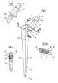
- the shaft 1which is designed as a straight shaft in the example shown and consists of metal, for example a titanium alloy, widens conically on all sides from its distal end 2. Its lateral narrow side 3 initially merges into the horizontal via a circular arc and opens into a prosthetic neck 4; this in turn carries a conical pin 5, on which a joint head, not shown, can be attached.
- the medial narrow side 6 of the shaftruns in a continuously curved curve and ends at a collar 7 which separates the prosthesis neck 4 from the actual shaft body 1 separates.
- the base of the collar 7,which can be oriented, for example, perpendicular to the axis 8 of the prosthesis neck 4, forms a relatively large support surface with which the collar 7 is supported on the cortex tissue of the femur bone, not shown.
- the medial narrow side 6has a slot 9 which widens laterally into a bubble-like recess 10 in the shaft body 1.
- the recess 10extends in the direction of the large trochanter up to approximately the longitudinal center plane 11 of the straight shaft 1.
- a bridge-like arch 12connects the distal part of the shaft 1 to the collar 7 or the prosthesis neck 4 4 shows, the "bridge arch" 12 has a substantially square cross section. Its shape and its dimensions are determined on the one hand by the required minimum strength for the shaft 1 and on the other hand - as already described - by the desired "elasticity" of the collar 7, which should be matched to that of the cortical bone tissue.
- the recess 10is filled by a highly elastic filler 13, which in the present example consists of polyurethane.
- a highly elastic filler 13which in the present example consists of polyurethane.
- the base area of the collar 7, which comes to rest on the bone,can be provided with a structure which promotes the growth of the bone.
Landscapes
- Health & Medical Sciences (AREA)
- Orthopedic Medicine & Surgery (AREA)
- Cardiology (AREA)
- Oral & Maxillofacial Surgery (AREA)
- Transplantation (AREA)
- Engineering & Computer Science (AREA)
- Biomedical Technology (AREA)
- Heart & Thoracic Surgery (AREA)
- Vascular Medicine (AREA)
- Life Sciences & Earth Sciences (AREA)
- Animal Behavior & Ethology (AREA)
- General Health & Medical Sciences (AREA)
- Public Health (AREA)
- Veterinary Medicine (AREA)
- Prostheses (AREA)
- Materials For Medical Uses (AREA)
Abstract
Description
Translated fromGermanDie Erfindung betrifft einen Verankerungsschaft für eine Femurkopfprothese, bei der zwischen dem in den Femur implantierbaren Schaft und dem den Gelenkkopf tragenden Prothesenhals zur Abstützung auf dem Femurknochen ein Kragen angeordnet ist.The invention relates to an anchoring shaft for a femoral head prosthesis, in which a collar is arranged between the shaft implantable in the femur and the prosthetic neck supporting the joint head for support on the femur bone.
Eine proximale Weiterleitung der Druckbelastungen von einer Prothese auf den Femurknochen erfolgt sehr häufig über den Kragen der Prothese, der den Prothesenhals von dem eigentlichen Schaft trennt und sich für eine derartige Kraftübertragung auf den kortikalen Rand der Resektionsebene abstützen muss.A proximal transfer of the pressure loads from a prosthesis to the femur bone very often takes place via the collar of the prosthesis, which separates the neck of the prosthesis from the actual shaft and must be supported on the cortical edge of the resection plane for such a force transmission.
Es hat sich nun gezeigt, dass es infolge der Belastungsänderungen am Gelenkkopf zu Wechselbelastungen zwischen Kragen und kortikalem Knochengewebe kommt, die im Laufe der Zeit zum Abbau des Knochens und damit mindestens zu einer Verminderung der maximalen Krafteinleitung in den Knochen führt.It has now been shown that, due to changes in the load on the joint head, there is an alternating load between the collar and the cortical bone tissue, which over time leads to the breakdown of the bone and thus at least to a reduction in the maximum force input into the bone.
Aufgabe der Erfindung ist es daher, einen Verankerungsschaft zu schaffen, bei dem ein inniger und möglichst weitgehend konstanter Kontakt des Kragens mit dem Knochen möglichst bei allen wechselnden Belastungen, die auf den Gelenkkopf der Prothese wirken, gewährleistet ist. Diese Aufgabe wird mit der Erfindung dadurch gelöst, dass der Schaft medial unterhalb des und nahe dem Kragen einen Schlitz aufweist, der sich im Schaftkörper zu einer blasenförmigen Aussparung erweitert, und dass ferner mindestens die Aussparung mit einem Elastomer-Füllkörper gefüllt sind.The object of the invention is therefore to create an anchoring shaft in which an intimate and largely constant contact of the collar with the bone if possible with all changing loads that act on the joint head of the prosthesis. This object is achieved with the invention in that the shaft has a slot medially below and near the collar, which widens into a bubble-shaped recess in the shaft body, and that at least the recess is filled with an elastomer filler.
Bei ordnungsgemässer Implantation liegt der Kragen vor allem in seinem medialen Bereich bei der neuen Konstruktion unter einer Vorspannung auf dem Knochengewebe auf, da sich der Schlitz und die Aussparung aufgrund der Elastizität der lateral der Aussparung gelegenen brückenartigen Verbindung vom distalen Schaftteil zum Prothesenhals bzw. Prothesenkragen maulartig elastisch öffnet. Der Füllkörper in der Aussparung hat eine hohe Elastizität, damit er die durch die laterale Verbindung des Schaftkörpers bestimmte Elastizität im proximalen Schaftbereich nicht begrenzt oder einengt. Die Tiefe der Aussparung in lateraler Richtung und damit bei gegebener Schaftform die Querschnittsfläche der lateralen Verbindung können dabei mit Vorteil so gewählt werden, dass auf der einen Seite die notwendige Schaftfestigkeit gewährleistet ist, auf der anderen Seite jedoch die "Elastizität" des Kragens bei den wechselnden Belastungen mindestens weitgehend der Elastizität des kortikalen Knochenmaterials entspricht, so dass Knochen und Kragen bei ihr elastischen "Schwingungen" infolge der Be- und Entlastungen möglichst gleiche Wege zurücklegen. Dadurch kann die Konstanz des Kragenskontaktes mit dem Knochen verbessert werden. Infolge seiner grossen Elastizität weicht der Füllkörper darüberhinaus bei Druckbelastungen mit seinem verdrängten Volumen in Richtungen quer zur Längsachse des Schaftes aus, wodurch seine Anpressung an die Wand des Operationshohlraumes vergrössert wird. Eine weitere Aufgabe des Füllkörpers besteht darin, ein Durch- und Einwachsen von Gewebe in die Ausparung zu verhindern.With proper implantation, the collar, especially in its medial area, rests on the bone tissue with a prestress under the new construction, since the slot and the recess muzzle-like from the distal shaft part to the prosthesis neck or prosthesis collar due to the elasticity of the bridge-like connection located laterally of the recess elastic opens. The filler body in the recess has a high elasticity, so that it does not limit or restrict the elasticity in the proximal area of the shaft determined by the lateral connection of the shaft body. The depth of the recess in the lateral direction and thus the cross-sectional area of the lateral connection for a given shaft shape can advantageously be chosen such that the necessary shaft strength is guaranteed on one side, but the "elasticity" of the collar on the other side with the changing ones Stresses correspond at least to a large extent to the elasticity of the cortical bone material, so that the bones and collars travel as evenly as possible as a result of their elastic "vibrations" as a result of the loading and unloading. This can improve the consistency of the collar contact with the bone. As a result of its great elasticity, the filler body also deflects with its displaced volume in directions transverse to the longitudinal axis of the shaft under pressure loads, as a result of which its pressure on the wall of the surgical cavity is increased. Another task of Packing consists in preventing tissue from growing through and growing into the recess.
Als Material für den Füllkörper haben sich Silikone und Polyurethane mit Shore A-Härten von 50 bis 80 und Shore D-Härten von 30 bis 60 als besonders geeignet erwiesen; weiterhin hat sich gezeigt, dass am medialen Rand Schlitzbreiten von 2 bis 4 mm einen ausreichenden Spielraum für eine Bewegung des Kragens bei Druckbelastungen gewährleisten.Silicones and polyurethanes with Shore A hardness from 50 to 80 and Shore D hardness from 30 to 60 have proven to be particularly suitable as the material for the packing. Furthermore, it has been shown that slot widths of 2 to 4 mm at the medial edge ensure sufficient scope for movement of the collar under pressure loads.
Im folgenden wird die Erfindung anhand eines Ausführungsbeispiels im Zusammenhang mit der Zeichnung näher erläutert.
- Fig. 1 zeigt eine Ansicht des neuen Schaftes von anterior oder posterior her;
- Fig. 2 gibt eine Ansicht des proximalen Bereichs von Fig. 1 von rechts wieder, während
- Fig. 3 und 4 die Schnitte III-III und IV-IV darstellen.
- Fig. 1 shows a view of the new shaft from anterior or posterior;
- FIG. 2 shows a view of the proximal region of FIG. 1 from the right while
- 3 and 4 represent the sections III-III and IV-IV.
Der in dem gezeigten Beispiel als Geradschaft ausgebildete Schaft 1, der aus Metall, beispielsweise einer Titanlegierung besteht, erweitert sich von seinem distalen Ende 2 allseitig konisch. Seine laterale Schmalseite 3 geht proximal über einen Kreisbogen zunächst in die Horizontale über und mündet in einen Prothesenhals 4; dieser trägt seinerseits einen konischen Zapfen 5, auf den ein nicht dargestellter Gelenkkopf aufsteckbar ist.The shaft 1, which is designed as a straight shaft in the example shown and consists of metal, for example a titanium alloy, widens conically on all sides from its distal end 2. Its lateral
Aus dem sich erweiternden Konus heraus verläuft die mediale Schmalseite 6 des Schaftes in einer stetig gekrümmter Kurve und endet an einem Kragen 7, der den Prothesenhals 4 von dem eigentlichen Schaftkörper 1 trennt. Die Grundfläche des Kragens 7, die z.B. senkrecht zur Achse 8 des Prothesenhalses 4 ausgerichtet sein kann, bildet eine relativ grosse Abstützfläche, mit der sich der Kragen 7 auf dem koritikalen Gewebe des nicht dargestellten Femurknochens abstützt.Out of the widening cone, the medial
Wenige Millimeter unterhalb des Kragens 7 weist die mediale Schmalseite 6 einen Schlitz 9 auf, der sich nach lateral zu einer blasenartigen Aussparung 10 im Schaftkörper 1 erweitert. In dem gezeigten Beispiel erstreckt sich die Aussparung 10 in Richtung auf den grossen Trochanter bis etwa zur Längsmittelebene 11 des Geradschaftes 1. Jenseits von dieser verbindet ein brückenartiger Bogen 12 den distalen Teil des Schaftes 1 mit dem Kragen 7 bzw. dem Prothesenhals 4. Wie Fig. 4 zeigt, weist der "Brückenbogen" 12 einen im wesentlichen quadratischen Querschnitt auf. Seine Form und seine Abmessungen sind einerseits durch die geforderte Mindestfestigkeit für den Schaft 1 und andererseits - wie bereits geschildert - durch die gewünschte "Elastizität" des Kragens 7 bestimmt, die an diejenige des kortikalen Knochengewebes angeglichen sein soll.A few millimeters below the collar 7, the medial
Ausgefüllt wird die Aussparung 10 von einem hochelastischen Füllkörper 13, der im vorliegenden Beispiel aus Polyurethan besteht. Er kann an seinen, sich im Knochen abstützenden Oberflächen 14 mit einer, das Anwachsen von Gewebe fördernden Beschichtung, beispielsweise aus Hydroxylapatit belegt sein. Ebenso kann man die Grundfläche des Kragens 7, die auf dem Knochen zur Auflage kommt, mit einer, ein Anwachsen des Knochens fördernden Struktur versehen sein.The
Claims (5)
Translated fromGermanPriority Applications (1)
| Application Number | Priority Date | Filing Date | Title |
|---|---|---|---|
| AT90810336TATE84697T1 (en) | 1989-06-21 | 1990-05-03 | ANCHORING STEM FOR A FEMURAL HEAD PROSTHESIS. |
Applications Claiming Priority (2)
| Application Number | Priority Date | Filing Date | Title |
|---|---|---|---|
| CH2316/89 | 1989-06-21 | ||
| CH2316/89ACH678595A5 (en) | 1989-06-21 | 1989-06-21 |
Publications (2)
| Publication Number | Publication Date |
|---|---|
| EP0404716A1true EP0404716A1 (en) | 1990-12-27 |
| EP0404716B1 EP0404716B1 (en) | 1993-01-20 |
Family
ID=4230956
Family Applications (1)
| Application Number | Title | Priority Date | Filing Date |
|---|---|---|---|
| EP90810336AExpired - LifetimeEP0404716B1 (en) | 1989-06-21 | 1990-05-03 | Anchored shaft for a femoral prosthesis |
Country Status (6)
| Country | Link |
|---|---|
| US (1) | US5197988A (en) |
| EP (1) | EP0404716B1 (en) |
| AT (1) | ATE84697T1 (en) |
| CH (1) | CH678595A5 (en) |
| DE (1) | DE59000785D1 (en) |
| ES (1) | ES2038511T3 (en) |
Cited By (5)
| Publication number | Priority date | Publication date | Assignee | Title |
|---|---|---|---|---|
| EP0486422A1 (en)* | 1990-11-16 | 1992-05-20 | SULZER Medizinaltechnik AG | Anchoring shaft for a femoral head prosthesis |
| FR2691898A1 (en)* | 1992-06-05 | 1993-12-10 | Medinov Sa | Femoral shaft component for hip joint replacement prosthesis - has semi-circular recess formed in inner lateral face in metaphyseal region, shaped as function of shaft curvature |
| EP0640326A1 (en)* | 1993-08-30 | 1995-03-01 | SULZER Medizinaltechnik AG | Element for temporarily increasing the rigidity of a prosthesis |
| US5549706A (en)* | 1993-02-09 | 1996-08-27 | Howmedica Inc. | Modular hip prosthesis |
| EP1872744A1 (en)* | 2006-06-29 | 2008-01-02 | HAVITCIOGLU, Hasan | Hip joint prosthesis |
Families Citing this family (14)
| Publication number | Priority date | Publication date | Assignee | Title |
|---|---|---|---|---|
| US7323013B2 (en)* | 1998-04-14 | 2008-01-29 | Encore Medical Asset Corporation | Differential porosity prosthetic hip system |
| US20040010319A1 (en)* | 1998-04-14 | 2004-01-15 | Osteoimplant Technology Inc. | Intrinsic stability in a total hip stem |
| US7497874B1 (en) | 2001-02-23 | 2009-03-03 | Biomet Manufacturing Corp. | Knee joint prosthesis |
| US20020120340A1 (en) | 2001-02-23 | 2002-08-29 | Metzger Robert G. | Knee joint prosthesis |
| US7534271B2 (en)* | 2004-01-22 | 2009-05-19 | Smith + Nephew | Femoral hip prosthesis and method of implantation |
| US8579985B2 (en) | 2006-12-07 | 2013-11-12 | Ihip Surgical, Llc | Method and apparatus for hip replacement |
| US8974540B2 (en) | 2006-12-07 | 2015-03-10 | Ihip Surgical, Llc | Method and apparatus for attachment in a modular hip replacement or fracture fixation device |
| EP2094197B8 (en)* | 2006-12-07 | 2016-03-09 | IHip Surgical, LLC | Apparatus for total hip replacement |
| US8187280B2 (en) | 2007-10-10 | 2012-05-29 | Biomet Manufacturing Corp. | Knee joint prosthesis system and method for implantation |
| US8562616B2 (en) | 2007-10-10 | 2013-10-22 | Biomet Manufacturing, Llc | Knee joint prosthesis system and method for implantation |
| JP5448842B2 (en) | 2007-01-10 | 2014-03-19 | バイオメト マニファクチャリング コーポレイション | Knee joint prosthesis system and implantation method |
| US8163028B2 (en) | 2007-01-10 | 2012-04-24 | Biomet Manufacturing Corp. | Knee joint prosthesis system and method for implantation |
| US8328873B2 (en) | 2007-01-10 | 2012-12-11 | Biomet Manufacturing Corp. | Knee joint prosthesis system and method for implantation |
| TWI634881B (en)* | 2015-04-21 | 2018-09-11 | 寶楠生技股份有限公司 | Femoral stem with cushion |
Citations (4)
| Publication number | Priority date | Publication date | Assignee | Title |
|---|---|---|---|---|
| US4187559A (en)* | 1975-04-04 | 1980-02-12 | Sybron Corporation | Body joint endoprosthesis |
| EP0220803A2 (en)* | 1985-09-16 | 1987-05-06 | Dow Corning Corporation | Multiple component hip femoral prosthesis |
| EP0359672A1 (en)* | 1988-09-16 | 1990-03-21 | Francis Henri Bréard | Articulation prosthesis, in particular a hip prosthesis, with a self-damping property |
| EP0308297B1 (en)* | 1987-09-08 | 1991-08-14 | Pierre Teinturier | Total articular prosthesis, especially for the hip |
Family Cites Families (12)
| Publication number | Priority date | Publication date | Assignee | Title |
|---|---|---|---|---|
| US3896505A (en)* | 1970-03-31 | 1975-07-29 | Franz Donatus Timmermans | Endoprosthesis for the hipjoint |
| GB1504055A (en)* | 1975-06-02 | 1978-03-15 | English T | Femoral prosthesis |
| SU762871A1 (en)* | 1977-04-01 | 1980-09-15 | Bentsian L Solomyanskij | Endoprothesis of metaepiphys of long tubular bone |
| US4292695A (en)* | 1980-06-25 | 1981-10-06 | Lord Corporation | Prosthesis stem |
| US4314381A (en)* | 1980-06-25 | 1982-02-09 | Lord Corporation | Hip joint prosthesis |
| US4536894A (en)* | 1983-08-04 | 1985-08-27 | Galante Jorge O | Hip prosthesis with flared porous bony ingrowth pads |
| US4792339A (en)* | 1985-05-23 | 1988-12-20 | Laboratorium Fur Experiementelle Chirurgie, Forschungsinstitut | Self-locking stemmed component for a joint endo-prosthesis |
| US4892550A (en)* | 1985-12-30 | 1990-01-09 | Huebsch Donald L | Endoprosthesis device and method |
| JP2566769B2 (en)* | 1987-02-27 | 1996-12-25 | 京セラ株式会社 | Artificial joint |
| EP0325588B1 (en)* | 1987-08-15 | 1992-01-15 | Laboratorium Für Experimentelle Chirurgie Forschungsinstitut Davos | Dynamic self-locking stem for hip prosthesis |
| US4851008A (en)* | 1988-02-01 | 1989-07-25 | Orthomet, Inc. | Bone implant prosthesis with substantially stress-free outer surface |
| US5201771A (en)* | 1989-09-15 | 1993-04-13 | Belykh Sergei I | Endoprosthesis of the hip joint |
- 1989
- 1989-06-21CHCH2316/89Apatent/CH678595A5/denot_activeIP Right Cessation
- 1990
- 1990-05-03ATAT90810336Tpatent/ATE84697T1/ennot_activeIP Right Cessation
- 1990-05-03ESES199090810336Tpatent/ES2038511T3/ennot_activeExpired - Lifetime
- 1990-05-03DEDE9090810336Tpatent/DE59000785D1/ennot_activeExpired - Fee Related
- 1990-05-03EPEP90810336Apatent/EP0404716B1/ennot_activeExpired - Lifetime
- 1990-05-23USUS07/528,108patent/US5197988A/ennot_activeExpired - Fee Related
Patent Citations (4)
| Publication number | Priority date | Publication date | Assignee | Title |
|---|---|---|---|---|
| US4187559A (en)* | 1975-04-04 | 1980-02-12 | Sybron Corporation | Body joint endoprosthesis |
| EP0220803A2 (en)* | 1985-09-16 | 1987-05-06 | Dow Corning Corporation | Multiple component hip femoral prosthesis |
| EP0308297B1 (en)* | 1987-09-08 | 1991-08-14 | Pierre Teinturier | Total articular prosthesis, especially for the hip |
| EP0359672A1 (en)* | 1988-09-16 | 1990-03-21 | Francis Henri Bréard | Articulation prosthesis, in particular a hip prosthesis, with a self-damping property |
Cited By (8)
| Publication number | Priority date | Publication date | Assignee | Title |
|---|---|---|---|---|
| EP0486422A1 (en)* | 1990-11-16 | 1992-05-20 | SULZER Medizinaltechnik AG | Anchoring shaft for a femoral head prosthesis |
| US5192331A (en)* | 1990-11-16 | 1993-03-09 | Sulzer Brothers Limited | Shank for a femur head prosthesis |
| FR2691898A1 (en)* | 1992-06-05 | 1993-12-10 | Medinov Sa | Femoral shaft component for hip joint replacement prosthesis - has semi-circular recess formed in inner lateral face in metaphyseal region, shaped as function of shaft curvature |
| US5549706A (en)* | 1993-02-09 | 1996-08-27 | Howmedica Inc. | Modular hip prosthesis |
| EP0640326A1 (en)* | 1993-08-30 | 1995-03-01 | SULZER Medizinaltechnik AG | Element for temporarily increasing the rigidity of a prosthesis |
| US5725590A (en)* | 1993-08-30 | 1998-03-10 | Sulzer Medizinaltechnik Ag | Element for temporarily increasing the rigidity of an orthopaedic prosthesis |
| US5735901A (en)* | 1993-08-30 | 1998-04-07 | Sulzer Medizinaltechnik Ag | Element for temporarily increasing the rigidity of an orthopaedic prosthesis |
| EP1872744A1 (en)* | 2006-06-29 | 2008-01-02 | HAVITCIOGLU, Hasan | Hip joint prosthesis |
Also Published As
| Publication number | Publication date |
|---|---|
| EP0404716B1 (en) | 1993-01-20 |
| US5197988A (en) | 1993-03-30 |
| ES2038511T3 (en) | 1993-07-16 |
| CH678595A5 (en) | 1991-10-15 |
| DE59000785D1 (en) | 1993-03-04 |
| ATE84697T1 (en) | 1993-02-15 |
Similar Documents
| Publication | Publication Date | Title |
|---|---|---|
| EP0404716B1 (en) | Anchored shaft for a femoral prosthesis | |
| EP0135755B1 (en) | Stem for a hip joint prosthesis | |
| DE69622452T2 (en) | Total anatomical hip prosthesis | |
| EP0240815B1 (en) | Plate-like shaft for the fixation of a hip joint prosthesis in the femur | |
| EP0971651B1 (en) | Hip joint endoprosthesis | |
| DE69917545T2 (en) | Implantable prosthesis with bone connecting ribs | |
| EP0222236B1 (en) | Rod for a femural-head prosthesis | |
| CH640407A5 (en) | Hip joint prosthesis. | |
| DE8237288U1 (en) | Femoral hip joint prosthesis | |
| EP0378044A1 (en) | Flat stem for a femoral head prosthesis | |
| EP0244610A1 (en) | Plate-like shaft for the fixation of a hip joint prosthesis in the femur | |
| CH659580A5 (en) | THE BIG TROCHANT REPLACING IMPLANT. | |
| DE2839092C3 (en) | One-piece thigh part of a hip joint endoprosthesis | |
| DE10320034A1 (en) | knee prosthesis | |
| DE2931750C2 (en) | One-piece thigh part of a hip joint endoprosthesis | |
| DE2517702C3 (en) | Femur part of a total hip joint replacement | |
| DE2514793B2 (en) | Joint endoprosthesis | |
| EP0145938B1 (en) | Intramedullary prosthesis | |
| CH647942A5 (en) | FEMUR HEAD PROSTHESIS. | |
| DE3338314A1 (en) | Tumour hip endoprosthesis | |
| AT518711B1 (en) | Shank for a hip joint prosthesis | |
| DE202014102059U1 (en) | Shank for a hip joint prosthesis | |
| DE2324865C3 (en) | Thigh part of a hip joint prosthesis | |
| EP4252715A1 (en) | Femur implant and femur implant set | |
| EP0325557A1 (en) | Endoprosthesis |
Legal Events
| Date | Code | Title | Description |
|---|---|---|---|
| PUAI | Public reference made under article 153(3) epc to a published international application that has entered the european phase | Free format text:ORIGINAL CODE: 0009012 | |
| AK | Designated contracting states | Kind code of ref document:A1 Designated state(s):AT BE DE ES FR GB IT NL SE | |
| 17P | Request for examination filed | Effective date:19901112 | |
| 17Q | First examination report despatched | Effective date:19920525 | |
| GRAA | (expected) grant | Free format text:ORIGINAL CODE: 0009210 | |
| ITF | It: translation for a ep patent filed | ||
| RAP1 | Party data changed (applicant data changed or rights of an application transferred) | Owner name:PROTEK AG Owner name:GEBRUEDER SULZER AKTIENGESELLSCHAFT | |
| AK | Designated contracting states | Kind code of ref document:B1 Designated state(s):AT BE DE ES FR GB IT NL SE | |
| REF | Corresponds to: | Ref document number:84697 Country of ref document:AT Date of ref document:19930215 Kind code of ref document:T | |
| REF | Corresponds to: | Ref document number:59000785 Country of ref document:DE Date of ref document:19930304 | |
| GBT | Gb: translation of ep patent filed (gb section 77(6)(a)/1977) | Effective date:19930208 | |
| ET | Fr: translation filed | ||
| REG | Reference to a national code | Ref country code:ES Ref legal event code:FG2A Ref document number:2038511 Country of ref document:ES Kind code of ref document:T3 | |
| PLBE | No opposition filed within time limit | Free format text:ORIGINAL CODE: 0009261 | |
| STAA | Information on the status of an ep patent application or granted ep patent | Free format text:STATUS: NO OPPOSITION FILED WITHIN TIME LIMIT | |
| 26N | No opposition filed | ||
| EAL | Se: european patent in force in sweden | Ref document number:90810336.9 | |
| PGFP | Annual fee paid to national office [announced via postgrant information from national office to epo] | Ref country code:GB Payment date:20010412 Year of fee payment:12 | |
| PGFP | Annual fee paid to national office [announced via postgrant information from national office to epo] | Ref country code:AT Payment date:20010427 Year of fee payment:12 | |
| PGFP | Annual fee paid to national office [announced via postgrant information from national office to epo] | Ref country code:SE Payment date:20010503 Year of fee payment:12 | |
| PGFP | Annual fee paid to national office [announced via postgrant information from national office to epo] | Ref country code:FR Payment date:20010507 Year of fee payment:12 | |
| PGFP | Annual fee paid to national office [announced via postgrant information from national office to epo] | Ref country code:NL Payment date:20010509 Year of fee payment:12 Ref country code:DE Payment date:20010509 Year of fee payment:12 | |
| PGFP | Annual fee paid to national office [announced via postgrant information from national office to epo] | Ref country code:ES Payment date:20010514 Year of fee payment:12 Ref country code:BE Payment date:20010514 Year of fee payment:12 | |
| REG | Reference to a national code | Ref country code:GB Ref legal event code:IF02 | |
| PG25 | Lapsed in a contracting state [announced via postgrant information from national office to epo] | Ref country code:GB Free format text:LAPSE BECAUSE OF NON-PAYMENT OF DUE FEES Effective date:20020503 Ref country code:AT Free format text:LAPSE BECAUSE OF NON-PAYMENT OF DUE FEES Effective date:20020503 | |
| PG25 | Lapsed in a contracting state [announced via postgrant information from national office to epo] | Ref country code:SE Free format text:LAPSE BECAUSE OF NON-PAYMENT OF DUE FEES Effective date:20020504 Ref country code:ES Free format text:LAPSE BECAUSE OF NON-PAYMENT OF DUE FEES Effective date:20020504 | |
| PG25 | Lapsed in a contracting state [announced via postgrant information from national office to epo] | Ref country code:BE Free format text:LAPSE BECAUSE OF NON-PAYMENT OF DUE FEES Effective date:20020531 | |
| PG25 | Lapsed in a contracting state [announced via postgrant information from national office to epo] | Ref country code:NL Free format text:LAPSE BECAUSE OF NON-PAYMENT OF DUE FEES Effective date:20021201 | |
| PG25 | Lapsed in a contracting state [announced via postgrant information from national office to epo] | Ref country code:DE Free format text:LAPSE BECAUSE OF NON-PAYMENT OF DUE FEES Effective date:20021203 | |
| GBPC | Gb: european patent ceased through non-payment of renewal fee | Effective date:20020503 | |
| EUG | Se: european patent has lapsed | ||
| PG25 | Lapsed in a contracting state [announced via postgrant information from national office to epo] | Ref country code:FR Free format text:LAPSE BECAUSE OF NON-PAYMENT OF DUE FEES Effective date:20030131 | |
| NLV4 | Nl: lapsed or anulled due to non-payment of the annual fee | Effective date:20021201 | |
| REG | Reference to a national code | Ref country code:FR Ref legal event code:ST | |
| REG | Reference to a national code | Ref country code:ES Ref legal event code:FD2A Effective date:20030611 | |
| PG25 | Lapsed in a contracting state [announced via postgrant information from national office to epo] | Ref country code:IT Free format text:LAPSE BECAUSE OF NON-PAYMENT OF DUE FEES;WARNING: LAPSES OF ITALIAN PATENTS WITH EFFECTIVE DATE BEFORE 2007 MAY HAVE OCCURRED AT ANY TIME BEFORE 2007. THE CORRECT EFFECTIVE DATE MAY BE DIFFERENT FROM THE ONE RECORDED. Effective date:20050503 |