EP0400481A1 - Packaging bag - Google Patents
Packaging bagDownload PDFInfo
- Publication number
- EP0400481A1 EP0400481A1EP90109881AEP90109881AEP0400481A1EP 0400481 A1EP0400481 A1EP 0400481A1EP 90109881 AEP90109881 AEP 90109881AEP 90109881 AEP90109881 AEP 90109881AEP 0400481 A1EP0400481 A1EP 0400481A1
- Authority
- EP
- European Patent Office
- Prior art keywords
- bag
- rectangular
- area
- edge
- sides
- Prior art date
- Legal status (The legal status is an assumption and is not a legal conclusion. Google has not performed a legal analysis and makes no representation as to the accuracy of the status listed.)
- Granted
Links
- 238000004806packaging method and processMethods0.000titleclaimsabstractdescription5
- 238000009461vacuum packagingMethods0.000claimsabstractdescription6
- 238000003466weldingMethods0.000claimsdescription13
- 235000013305foodNutrition0.000claimsdescription2
- 238000000034methodMethods0.000description3
- 238000004519manufacturing processMethods0.000description2
- 239000000463materialSubstances0.000description2
- XAGFODPZIPBFFR-UHFFFAOYSA-NaluminiumChemical compound[Al]XAGFODPZIPBFFR-UHFFFAOYSA-N0.000description1
- 229910052782aluminiumInorganic materials0.000description1
- 239000002131composite materialSubstances0.000description1
- 238000007796conventional methodMethods0.000description1
- 239000013013elastic materialSubstances0.000description1
- 239000011888foilSubstances0.000description1
- 238000012986modificationMethods0.000description1
- 230000004048modificationEffects0.000description1
- 239000002985plastic filmSubstances0.000description1
- 229920006255plastic filmPolymers0.000description1
- 238000002604ultrasonographyMethods0.000description1
Images

Classifications
- B—PERFORMING OPERATIONS; TRANSPORTING
- B65—CONVEYING; PACKING; STORING; HANDLING THIN OR FILAMENTARY MATERIAL
- B65D—CONTAINERS FOR STORAGE OR TRANSPORT OF ARTICLES OR MATERIALS, e.g. BAGS, BARRELS, BOTTLES, BOXES, CANS, CARTONS, CRATES, DRUMS, JARS, TANKS, HOPPERS, FORWARDING CONTAINERS; ACCESSORIES, CLOSURES, OR FITTINGS THEREFOR; PACKAGING ELEMENTS; PACKAGES
- B65D75/00—Packages comprising articles or materials partially or wholly enclosed in strips, sheets, blanks, tubes or webs of flexible sheet material, e.g. in folded wrappers
- B65D75/52—Details
- B65D75/58—Opening or contents-removing devices added or incorporated during package manufacture
- B65D75/5816—Opening or contents-removing devices added or incorporated during package manufacture for tearing a corner or other small portion next to the edge, e.g. a U-shaped portion
- B—PERFORMING OPERATIONS; TRANSPORTING
- B65—CONVEYING; PACKING; STORING; HANDLING THIN OR FILAMENTARY MATERIAL
- B65D—CONTAINERS FOR STORAGE OR TRANSPORT OF ARTICLES OR MATERIALS, e.g. BAGS, BARRELS, BOTTLES, BOXES, CANS, CARTONS, CRATES, DRUMS, JARS, TANKS, HOPPERS, FORWARDING CONTAINERS; ACCESSORIES, CLOSURES, OR FITTINGS THEREFOR; PACKAGING ELEMENTS; PACKAGES
- B65D75/00—Packages comprising articles or materials partially or wholly enclosed in strips, sheets, blanks, tubes or webs of flexible sheet material, e.g. in folded wrappers
- B65D75/52—Details
- B65D75/58—Opening or contents-removing devices added or incorporated during package manufacture
- B65D75/5805—Opening or contents-removing devices added or incorporated during package manufacture for tearing a side strip parallel and next to the edge, e.g. by means of a line of weakness
- B—PERFORMING OPERATIONS; TRANSPORTING
- B65—CONVEYING; PACKING; STORING; HANDLING THIN OR FILAMENTARY MATERIAL
- B65D—CONTAINERS FOR STORAGE OR TRANSPORT OF ARTICLES OR MATERIALS, e.g. BAGS, BARRELS, BOTTLES, BOXES, CANS, CARTONS, CRATES, DRUMS, JARS, TANKS, HOPPERS, FORWARDING CONTAINERS; ACCESSORIES, CLOSURES, OR FITTINGS THEREFOR; PACKAGING ELEMENTS; PACKAGES
- B65D75/00—Packages comprising articles or materials partially or wholly enclosed in strips, sheets, blanks, tubes or webs of flexible sheet material, e.g. in folded wrappers
- B65D75/04—Articles or materials wholly enclosed in single sheets or wrapper blanks
- B65D75/06—Articles or materials wholly enclosed in single sheets or wrapper blanks in sheets or blanks initially folded to form tubes
- B65D75/12—Articles or materials wholly enclosed in single sheets or wrapper blanks in sheets or blanks initially folded to form tubes with the ends of the tube closed by flattening and heat-sealing
Definitions
- the inventionrelates to a tear-open pouch for packaging, especially for vacuum packaging, of foods, in particular of coffee.
- a tubular bag made of air-impermeable elastic materialis used for vacuum packaging various products, in particular ground or unground coffee, which is hermetically sealed and folded in such a way that a packaging is produced which essentially has the shape of a parallelepiped.
- the bagusually consists of an inner wrapper that comes into direct contact with the packaged goods and is enclosed by an outer wrapper that is folded over and folded in such a way that, like the bag that forms the inner wrapper, it is in the form of a parallelepiped.
- This end areaconsists of two rectangular surfaces which project upwards from the top of the bag and whose long sides each form the end edges of the opposite front sides of the bag and the folds at the level of the top of the bag, the bag passing through this rectangular area a linear region or a weld seam is closed, which run parallel to the longitudinal sides of the rectangular region and generally substantially at a half distance from these.
- the weld seamIn order to open the bag, the weld seam must be torn open in this rectangular area. Because of the mechanical properties of the material from which the pouch is made, for example a composite of plastic film and aluminum foil, this tear-open can only be carried out with difficulty, and above all in a way that is different for each pouch, so that consumers in In practice, use aids such as scissors to open the bag if the package cannot be easily torn open.
- the object of the inventionis to create a bag which, thanks to particularly simple and economical means, allows the bag to be opened quickly by simply tearing it open, the opening process taking place reliably in the same way for each package, while also opening an opening area which is released serves as a pouring spout.
- the bag according to the inventionis essentially characterized in that it has a continuous cutout in the upper rectangular end region, essentially in the middle thereof, the edge of which extends essentially perpendicular to the long sides of the rectangular region, while its upper end lies between the weld seam and the upper one Longitudinal side of the rectangular area is located, which edge extends substantially at right angles to the lower end in an edge which is substantially parallel to the long sides of the rectangular area between the weld seam and the lower longitudinal edge of the rectangular area.
- This cutoutis preferably triangular, in particular in the form of a right-angled triangle.
- the cutoutcan be formed using any suitable method, preferably it is punched out.
- the bag in the upper rectangular end regionhas a central, for example rectangular, weld region, which covers the weld seam in the central section, the cutout in this weld region being formed such that the upper end of its edge, which is essentially extends perpendicular to the long sides of the rectangular end region of the bag, projects beyond the upper edge of the central welding region and upwards to the upper long side of the rectangular region.
- two further lateral welding areasare provided which run from the narrow sides of the rectangular end area between the longitudinally extending weld seam and the lower longitudinal side of the rectangular area.
- the welded areasare produced with the aid of any conventional method which is suitable for this in view of the type of material used for the bag, for example, heat or ultrasound can be used here occasionally.
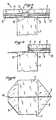
- FIGS. 1 to 3From Fig. 1, a bag according to the invention can be seen in the completely closed state, which is folded over or crimped in such a way that it forms a body which essentially has the shape of a parallelepiped 1 with a flat top, onto which two triangular tabs 3 are folded will.
- a rectangular upper end region 4is formed on the upper section of the bag, which relates Lich the rectangular top 2 of the bag extends transversely between the tip regions of the triangular tabs 3.
- the longitudinal side 5 of the rectangular areawhich forms the upper edge of this area, is thus formed in that the end edges of the opposite sides of the bag are placed side by side in the upper section thereof.
- the lower longitudinal side 6is formed by folding the ends of the opposite bag sides relative to the bag sections that form the top 2 and the tabs 3.
- the bagis closed in the area 4 in a conventional manner with the aid of a weld seam 7, which extends over its entire length essentially half the distance from the upper (5) and lower (6) long sides.
- This weld seamwhich is created, for example, by the action of heat, hermetically seals the bag.
- a cutout 8is provided which is triangular in the exemplary embodiment shown, this cutout having an edge 9 running perpendicular to the sides 5 and 6, which continues in an edge which is arranged parallel to these longitudinal sides 5 and 6 , wherein the two edges 9 and 10 are connected to each other by an edge which runs obliquely so that a cutout in the form of a right-angled triangle is formed.
- This cutoutruns through the two walls that form the rectangular end region 4, for example by it is punched in using an appropriately shaped tool.
- This cutout 8is formed in a welding area 11, which is rectangular in the exemplary embodiment shown, the upper end of the edge 9 of the cutout 8 projecting upward from the upper edge of the welding area 11.
- This welding area 11is essentially formed in the central section of area 4. In the illustrated embodiment, this area is slightly offset to the left from the center of area 4.
- the central welding area 11is arranged on both sides and covers the weld seam 7, while the zones 12 and 13 are arranged between the weld seam 7 and the lower longitudinal side 6 of the rectangular area 4.
- the tabs 3are turned over from the position shown in FIG. 1 so that they are in the position shown in FIG. 2.
- a gap 14is formed in the upper section of the bag, which forms an opening after the end edges of the bag have been raised while forming a filling nozzle.
- cutout 8 for opening the bagdefines predetermined breaking lines in such a way that a simple, reliable and constant opening is possible with all bags.
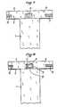
- FIG 7 and 8illustrate two phases in the manufacture of the upper end portion of the bag according to the invention.
- the cutout 8is punched out, as shown in FIG. 8, whereupon a vacuum is created in order to create a vacuum in the interior of the bag, and finally the bag is closed completely tightly by placing a weld seam along line 7.
- the pouch shown in the drawingcan of course be used in the form thus formed, but it preferably forms an inner wrapper which is within an Au Outer wrapping is located, so that a double-walled package is created, for example for vacuum packing of ground or unground coffee.
Landscapes
- Engineering & Computer Science (AREA)
- Mechanical Engineering (AREA)
- Packages (AREA)
- Bag Frames (AREA)
- Packging For Living Organisms, Food Or Medicinal Products That Are Sensitive To Environmental Conditiond (AREA)
Abstract
Description
Translated fromGermanDie Erfindung bezieht sich auf einen Aufreißbeutel zur Verpackung, speziell zur Vakuumverpackung, von Nahrungsmitteln, insbesondere von Kaffee.The invention relates to a tear-open pouch for packaging, especially for vacuum packaging, of foods, in particular of coffee.
Üblicherweise wird zur Vakuumverpackung verschiedener Produkte, insbesondere von gemahlenem oder ungemahlenem Kaffee, ein Schlauchbeutel aus luftundurchlässigem elastischen Material verwendet, der hermetisch verschlossen und so gefaltet ist, daß eine Verpackung entsteht, die im wesentlichen die Form eines Parallelepipeds aufweist. Der Beutel besteht in der Praxis meistens aus einer Innenumhüllung, die direkt mit der verpackten Ware in Berührung kommt und ist von einer Außenumhüllung umschlossen, die so umgeschlagen und gefaltet wird, daß sie ebenso wie der die Innenumhüllung bildende Beutel die Form eines Parallelepipeds aufweist.Usually, a tubular bag made of air-impermeable elastic material is used for vacuum packaging various products, in particular ground or unground coffee, which is hermetically sealed and folded in such a way that a packaging is produced which essentially has the shape of a parallelepiped. In practice, the bag usually consists of an inner wrapper that comes into direct contact with the packaged goods and is enclosed by an outer wrapper that is folded over and folded in such a way that, like the bag that forms the inner wrapper, it is in the form of a parallelepiped.
Zum Öffnen des auf diese Weise aus zwei Umhüllungen gebildeten Pakets müssen die beiden dreieckigen Lappen, die an der Vorderseite am oberen Ende des Pakets ausgebildet sind, durch Auseinanderklappen so angehoben werden, daß der obere Endbereich des Beutels freigelegt wird. Dieser Endbereich besteht aus zwei rechteckförmigen Flächen, die von der Oberseite des Beutels nach oben überstehen und deren Längsseiten jeweils die Abschlußkanten der gegenüberliegenden Vorderseiten des Beutels und der Falze in Höhe der Oberseite des Beutels bilden, wobei der Beutel in diesem rechteckigen Bereich durch einen linearen Bereich bzw. eine Schweißnaht verschlossen ist, die parallel zu den Längsseiten des rechteckigen Bereichs und im allgemeinen im wesentlichen auf halbem Abstand von diesen verlaufen.To open the package formed from two wrappers in this way, the two triangular tabs formed on the front at the top of the package must be lifted open to expose the top end of the bag. This end area consists of two rectangular surfaces which project upwards from the top of the bag and whose long sides each form the end edges of the opposite front sides of the bag and the folds at the level of the top of the bag, the bag passing through this rectangular area a linear region or a weld seam is closed, which run parallel to the longitudinal sides of the rectangular region and generally substantially at a half distance from these.
Um den Beutel zu öffnen,muß die Schweißnaht in diesem rechteckigen Bereich aufgerissen werden. Wegen der mechanischen Eigenschaften des Materials, aus dem der Beutel besteht, beispielsweise eines Verbunds aus Kunststoffolie und Aluminiumfolie, läßt sich dieses Aufreißen nur mit Schwierigkeiten vornehmen, und vor allem in einer Weise, die bei jedem Beutel wieder anders ist, so daß die Verbraucher in der Praxis mit Auftrennhilfen wie beispielsweise Scheren arbeiten, um den Beutel zu öffnen, wenn sich das Paket nicht einfach aufreißen läßt.In order to open the bag, the weld seam must be torn open in this rectangular area. Because of the mechanical properties of the material from which the pouch is made, for example a composite of plastic film and aluminum foil, this tear-open can only be carried out with difficulty, and above all in a way that is different for each pouch, so that consumers in In practice, use aids such as scissors to open the bag if the package cannot be easily torn open.
Der Erfindung liegt nun die Aufgabe zugrunde, einen Beutel zu schaffen, der dank besonders einfacher und wirtschaftlicher Mittel ein rasches Öffnen des Beutels durch einfaches Aufreißen gestattet, wobei der Öffnungsvorgang zuverlässig bei jedem Paket in gleicher Weise abläuft, während darüberhinaus ein Öffnungsbereich freigegeben wird, der als Schüttülle dient.The object of the invention is to create a bag which, thanks to particularly simple and economical means, allows the bag to be opened quickly by simply tearing it open, the opening process taking place reliably in the same way for each package, while also opening an opening area which is released serves as a pouring spout.
Der erfindungsgemäße Beutel zeichnet sich im wesentlichen dadurch aus, daß er im oberen rechteckigen Endbereich im wesentlichen in dessen Mitte einen durchgehenden Ausschnitt aufweist, dessen Kante im wesentlichen senkrecht zu den Längsseiten des rechteckigen Bereichs verläuft, während sein oberes Ende sich zwischen der Schweißnaht und der oberen Längsseite des rechteckigen Bereichs befindet, wobei diese Kante sich im wesentlichen unter einem rechten Winkel zum unteren Ende in einem Rand fortsetzt, der im wesentlichen parallel zu den Längsseiten des rechteckigen Bereichs zwischen der Schweißnaht und der unteren Längskante des rechteckigen Bereichs verläuft.The bag according to the invention is essentially characterized in that it has a continuous cutout in the upper rectangular end region, essentially in the middle thereof, the edge of which extends essentially perpendicular to the long sides of the rectangular region, while its upper end lies between the weld seam and the upper one Longitudinal side of the rectangular area is located, which edge extends substantially at right angles to the lower end in an edge which is substantially parallel to the long sides of the rectangular area between the weld seam and the lower longitudinal edge of the rectangular area.
Vorzugsweise ist dieser Ausschnitt dreieckig, insbesondere in Form eines rechtwinkligen Dreiecks, ausgebildet. Der Ausschnitt kann mit jedem hierzu geeigneten Verfahren ausgebildet werden, vorzugsweise wird er ausgestanzt.This cutout is preferably triangular, in particular in the form of a right-angled triangle. The cutout can be formed using any suitable method, preferably it is punched out.
Es ist von Vorteil, wenn der Beutel im oberen rechteckigen Endbereich einen in der Mitte liegenden, beispielsweise rechteckigen Schweißbereich aufweist, der die Schweißnaht im Mittelabschnitt überdeckt, wobei der Ausschnitt in diesem Schweißbereich so ausgebildet wird, daß das obere Ende seines Randes, der im wesentlichen senkrecht zu den Längsseiten des rechteckigen Endbereichs des Beutels verläuft, über den oberen Rand des in der Mitte liegenden Schweißbereichs hinaus nach oben zur oberen Längsseite des rechteckigen Bereichs hin übersteht.It is advantageous if the bag in the upper rectangular end region has a central, for example rectangular, weld region, which covers the weld seam in the central section, the cutout in this weld region being formed such that the upper end of its edge, which is essentially extends perpendicular to the long sides of the rectangular end region of the bag, projects beyond the upper edge of the central welding region and upwards to the upper long side of the rectangular region.
Gemäß einem besonderen Merkmal der Erfindung sind außer dem in der Mitte liegenden Schweißbereich zwei weitere seitliche Schweißbereiche vorgesehen, die von den Schmalseiten des rechteckigen Endbereichs aus zwischen der in Längsrichtung verlaufenden Schweißnaht und der unteren Längsseite des rechteckigen Bereichs verlaufen.According to a special feature of the invention, in addition to the welding area lying in the middle, two further lateral welding areas are provided which run from the narrow sides of the rectangular end area between the longitudinally extending weld seam and the lower longitudinal side of the rectangular area.
Die Schweißbereiche werden mit Hilfe jedes herkömmlichen Verfahrens hergestellt, das sich angesichts der Art des für den Beutel verwendeten Materials hierfür eignet, beispielsweise kann hier fallweise mit Wärmeeinwirkung oder mit Ultraschall gearbeitet werden.The welded areas are produced with the aid of any conventional method which is suitable for this in view of the type of material used for the bag, for example, heat or ultrasound can be used here occasionally.
Weitere Vorteile und Merkmale des erfindungsgemäßen Beutels und der Verfahrensweise bei dessen Öffnung ergeben sich aus der nachstehenden Beschreibung anhand eines Ausführungsbei spiels unter Bezugnahme auf die beigefügte Zeichnung. Es zeigen:
- Fig. 1 einen Beutel der erfindungsgemäßen Art in vollständig verschlossener Stellung,
- Fig. 2 die Anordnung des Beutels in der Stellung, in der die Öffnung vorgenommen werden kann.
- Fig. 3 eine teilweise Vorderansicht des Beutels aus Fig. 2,
- Fig. 4 eine Ansicht
ähnlich Figur 3, allerdings mit der Darstellung des Aufreißvorgangs am Beutel bei dessen Öffnung, - Fig. 5 eine Ansicht ähnlich Fig. 3 und 4, mit der Darstellung der Anordnung des Beutels in geöffnetem Zustand,
- Fig. 6 eine Fig. 5 entsprechende Draufsicht, und
- Fig. 7 und 8 jeweils eine Ansicht ähnlich Fig. 3, mit der Darstellung verschiedener aufeinanderfolgender bei der Herstellung des erfindungsgemäßen Beutels.
- 1 is a bag of the type according to the invention in the fully closed position,
- Fig. 2 shows the arrangement of the bag in the position in which the opening can be made.
- 3 is a partial front view of the bag of FIG. 2,
- 4 shows a view similar to FIG. 3, but with the representation of the tearing open of the bag when it is opened,
- 5 is a view similar to FIGS. 3 and 4, showing the arrangement of the bag in the open state,
- Fig. 6 is a plan view corresponding to Fig. 5, and
- 7 and 8 are each a view similar to FIG. 3, showing various successive in the manufacture of the bag according to the invention.
Zunächst wird auf die Figuren 1 bis 3 Bezug genommen. Aus Fig. 1 ist ein erfindungsgemäßer Beutel in vollständig verschlossenem Zustand zu entnehmen, der so umgeschlagen bzw. eingefalzt ist, daß er einen Körper bildet, der im wesentlichen die Form eines Parallelepipeds 1 mit einer flachen Oberseite aufweist, auf welche zwei dreieckige Lappen 3 umgeschlagen werden.First, reference is made to FIGS. 1 to 3. From Fig. 1, a bag according to the invention can be seen in the completely closed state, which is folded over or crimped in such a way that it forms a body which essentially has the shape of a parallelepiped 1 with a flat top, onto which two
Wegen der speziellen Form des gebildeten Umschlags, die an sich üblich ist, bildet man am oberen Abschnitt des Beutels einen rechteckigen oberen Endbereich 4 aus, der sich bezüg lich der rechteckigen Oberseite 2 des Beutels quer zwischen den Spitzenbereichen der dreieckigen Lappen 3 erstreckt.Because of the special shape of the envelope formed, which is common per se, a rectangular
Dieser rechteckige Bereich 4, der gemäß Fig. 2 nach oben übersteht, sobald die dreieckigen Lappen 3 aus der in Fig. 1 gezeigten Stellung aufgeklappt sind, wird tatsächlich dadurch gebildet, daß die einander gegenüberliegenden Enden des Beutels gegeneinander angelegt werden.This
Die Längsseite 5 des rechteckigen Bereichs, die die Oberkante dieses Bereichs bildet, wird somit dadurch gebildet, daß die Abschlußkanten der gegenüberliegenden Seiten des Beutels im oberen Abschnitt desselben nebeneinander gelegt werden. Die untere Längsseite 6 wird durch Falze der Enden der gegenüberliegenden Beutelseiten relativ zu den Beutelabschnitten gebildet, die die Oberseite 2 und die Lappen 3 bilden.The
Der Beutel wird im Bereich 4 in herkömmlicher Weise mit Hilfe einer Schweißnaht 7 verschlossen, die sich über dessen gesamte Länge im wesentlichen im halben Abstand von der oberen (5) und unteren (6) Längsseite erstreckt. Diese Schweißnaht, die beispielsweise durch Wärmeeinwirkung gelegt wird, verschließt den Beutel hermetisch.The bag is closed in the
Erfindungsgemäß ist die Ausbildung eines Ausschnitts 8 vorgesehen, der bei dem dargestellten Ausführungsbeispiel dreieckförmig ist, wobei diese Aussparung einen senkrecht zu den Seiten 5 und 6 verlaufenden Rand 9 aufweist, der sich in einem Rand fortsetzt, der parallel zu diesen Längsseiten 5 und 6 angeordneten verläuft, wobei die beiden Ränder 9 und 10 durch eine Kante miteinander verbunden sind, die so schräg verläuft, daß ein Ausschnitt in Form eines rechtwinkligen Dreiecks entsteht.According to the invention, a
Dieser Ausschnitt verläuft durch die beiden Wandungen, die den rechteckigen Endbereich 4 bilden, beispielsweise indem er mit Hilfe eines entsprechend geformten Werkzeugs eingestanzt wird.This cutout runs through the two walls that form the
Dieser Ausschnitt 8 ist in einem Schweißbereich 11, der bei dem dargestellten Ausführungsbeispiel rechteckförmig ist, ausgebildet, wobei das obere Ende des Randes 9 des Ausschnitts 8 von der Oberkante des Schweißbereichs 11 aus nach oben übersteht. Dieser Schweißbereich 11 ist im wesentlichen im mittleren Abschnitt des Bereichs 4 ausgebildet. Bei dem dargestellten Ausführungsbeispiel ist dieser Bereich gegenüber der Mitte des Bereichs 4 leicht nach links versetzt.This
Schließlich ist es erfindungsgemäß auch vorgesehen, in dem rechteckigen Bereich 4 zwei seitliche Schweißzonen 12 und 13 auszubilden, die vorzugsweise von den Schmalseiten des rechteckigen Bereichs 4 aus verlaufen. Wie aus der Zeichnung ersichtlich ist, ist der mittlere Schweißbereich 11 beiderseits angeordnet und überdeckt die Schweißnaht 7, während die Zonen 12 und 13 zwischen der Schweißnaht 7 und der unteren Längsseite 6 des rechteckigen Bereichs 4 angeordnet sind.Finally, it is also provided according to the invention to form two
Zum Öffnen des erfindungsgemäßen Beutels werden die Lappen 3 aus der in Fig. 1 dargestellten Lage so umgeschlagen, daß sie sich in der aus Fig. 2 zu entnehmenden Stellung befinden.To open the bag according to the invention, the
Der Verbraucher faßt nun mit einer Hand den rechten Teil des nach oben vorstehenden rechteckigen Bereichs 4 und mit der anderen Hand den linken Abschnitt dieses Bereichs.The consumer now grips the right part of the upwardly projecting
Anschließend übt er mit der anderen Hand eine Zugkraft nach oben im wesentlichen in Richtung des Pfeiles in Fig. 4 aus, um so das Aufreißen des Beutels zu veranlassen.He then exerts an upward tensile force essentially in the direction of the arrow in FIG. 4 with the other hand, so as to cause the bag to tear open.
Wegen des Ausschnitts 8 erfolgt dieses Aufreißen in der einzig möglichen Weise entlang den Linien, die schematisch in Fig. 4 gestrichelt eingezeichnet sind, so daß der gesamte linke Teil des Bereichs 4 aufgerissen wird. Fig. 5 und auch Fig. 6 zeigen den Beutel jeweils nach dem Aufreißen.Because of the
Wie aus Fig. 6 ersichtlich ist, bildet sich im oberen Abschnitt des Beutels ein Spalt 14, der nach dem Anheben der Abschlußkanten des Beutels unter Ausformung einer Schüttülle eine Öffnung bildet.As can be seen from FIG. 6, a
Daran wird deutlich, daß der Ausschnitt 8 zum Öffnen des Beutels Sollbruchlinien in der Weise festlegt, daß ein einfaches, zuverlässiges und bei allen Beuteln gleichbleibendes Öffnen möglich wird.This makes it clear that the
Die Fig. 7 und 8 veranschaulichen zwei Phasen bei der Herstellung des oberen Endbereichs des erfindungsgemäßen Beutels.7 and 8 illustrate two phases in the manufacture of the upper end portion of the bag according to the invention.
Aus Fig. 7 ist ersichtlich, daß die gegenüberliegenden Seiten des Beutels in Höhe ihrer Oberkanten durch Verschweißen in den Bereichen 11, 12, 13 in der in Fig. 7 dargestellten Weise vorläufig verschlossen werden, sobald das zu verpackende Gut in den Innenraum 1 des Beutels eingefüllt wurde.From Fig. 7 it can be seen that the opposite sides of the bag at the level of their upper edges are temporarily sealed by welding in the
Anschließend wird gemäß der Darstellung in Fig. 8 der Ausschnitt 8 ausgestanzt, worauf man einen Unterdruck anlegt, um im Innenraum des Beutels ein Vakuum zu erzeugen, und schließlich wird der Beutel völlig dicht verschlossen, indem entlang der Linie 7 eine Schweißnaht gelegt wird.Subsequently, the
Nun müssen nur noch die Lappen 3 umgeschlagen und fixiert werden, damit sie die aus Fig. 1 ersichtliche vollständig verschlossene Position einnehmen.Now only the
Der in der Zeichnung dargestellte Beutel kann natürlich in der so gebildeten Form verwendet werden, doch bildet er vorzugsweise eine Innenumhüllung, die sich innerhalb einer Au ßenumhüllung befindet, so daß ein doppelwandiges Paket entsteht, beispielsweise zur Vakuumerpackung von gemahlenem oder ungemahlenem Kaffee.The pouch shown in the drawing can of course be used in the form thus formed, but it preferably forms an inner wrapper which is within an Au Outer wrapping is located, so that a double-walled package is created, for example for vacuum packing of ground or unground coffee.
Selbstverständlich ist die Erfindung nicht nur auf diesen Verwendungszweck beschränkt. Auch wenn sie in Verbindung mit einem besonderen Ausführungsbeispiel erläutert wurde, so liegt es doch auf der Hand, daß sie keinesfalls (darauf) beschränkt ist und daß zahlreiche Veränderungen und Modifizierungen daran möglich sind, die völlig in den Rahmen der Erfindung fallen.Of course, the invention is not limited to this purpose only. Even if it was explained in connection with a particular exemplary embodiment, it is obvious that it is in no way restricted (to) and that numerous changes and modifications are possible that fall entirely within the scope of the invention.
Claims (7)
Translated fromGermanApplications Claiming Priority (2)
| Application Number | Priority Date | Filing Date | Title |
|---|---|---|---|
| FR8907006AFR2648442B1 (en) | 1989-05-29 | 1989-05-29 | BAG WITH FAST OPENING OF PACKAGING, IN PARTICULAR OF VACUUM PACKAGING, OF FOOD PRODUCTS IN PARTICULAR COFFEE |
| FR8907006 | 1989-05-29 |
Publications (2)
| Publication Number | Publication Date |
|---|---|
| EP0400481A1true EP0400481A1 (en) | 1990-12-05 |
| EP0400481B1 EP0400481B1 (en) | 1994-09-14 |
Family
ID=9382094
Family Applications (1)
| Application Number | Title | Priority Date | Filing Date |
|---|---|---|---|
| EP90109881AExpired - LifetimeEP0400481B1 (en) | 1989-05-29 | 1990-05-23 | Packaging bag |
Country Status (7)
| Country | Link |
|---|---|
| EP (1) | EP0400481B1 (en) |
| AT (1) | ATE111414T1 (en) |
| CA (1) | CA2017668A1 (en) |
| DE (1) | DE59007101D1 (en) |
| DK (1) | DK0400481T3 (en) |
| ES (1) | ES2060863T3 (en) |
| FR (1) | FR2648442B1 (en) |
Citations (3)
| Publication number | Priority date | Publication date | Assignee | Title |
|---|---|---|---|---|
| DE959716C (en)* | 1955-04-01 | 1957-03-07 | Agfa Ag Fuer Photofabrikation | Tear-open packaging |
| DE1486176A1 (en)* | 1963-01-16 | 1969-01-23 | Tetra Pak Ab | Pack made of bitgmmem and relatively stiff packaging material |
| US4176567A (en)* | 1977-03-18 | 1979-12-04 | Warren Weisberg | Method of making a tear line-forming perforation in a sealed marginal portion of a bag and a sealed bag formed thereby |
- 1989
- 1989-05-29FRFR8907006Apatent/FR2648442B1/ennot_activeExpired - Lifetime
- 1990
- 1990-05-23DKDK90109881.4Tpatent/DK0400481T3/enactive
- 1990-05-23ATAT90109881Tpatent/ATE111414T1/ennot_activeIP Right Cessation
- 1990-05-23DEDE59007101Tpatent/DE59007101D1/ennot_activeExpired - Fee Related
- 1990-05-23EPEP90109881Apatent/EP0400481B1/ennot_activeExpired - Lifetime
- 1990-05-23ESES90109881Tpatent/ES2060863T3/ennot_activeExpired - Lifetime
- 1990-05-28CACA002017668Apatent/CA2017668A1/ennot_activeAbandoned
Patent Citations (3)
| Publication number | Priority date | Publication date | Assignee | Title |
|---|---|---|---|---|
| DE959716C (en)* | 1955-04-01 | 1957-03-07 | Agfa Ag Fuer Photofabrikation | Tear-open packaging |
| DE1486176A1 (en)* | 1963-01-16 | 1969-01-23 | Tetra Pak Ab | Pack made of bitgmmem and relatively stiff packaging material |
| US4176567A (en)* | 1977-03-18 | 1979-12-04 | Warren Weisberg | Method of making a tear line-forming perforation in a sealed marginal portion of a bag and a sealed bag formed thereby |
Also Published As
| Publication number | Publication date |
|---|---|
| EP0400481B1 (en) | 1994-09-14 |
| FR2648442B1 (en) | 1991-09-20 |
| DK0400481T3 (en) | 1995-02-13 |
| DE59007101D1 (en) | 1994-10-20 |
| FR2648442A1 (en) | 1990-12-21 |
| ES2060863T3 (en) | 1994-12-01 |
| CA2017668A1 (en) | 1990-11-29 |
| ATE111414T1 (en) | 1994-09-15 |
Similar Documents
| Publication | Publication Date | Title |
|---|---|---|
| CH633232A5 (en) | OPENING DEVICE FOR PACKAGING MADE OF FLEXIBLE MATERIAL. | |
| WO1993002931A1 (en) | Package for liquids and process for producing the same | |
| EP0078403A2 (en) | Container for fluids provided with a plastics closure | |
| WO1990014291A1 (en) | Foil-like material for a folding package and such a folding package | |
| DE69105456T2 (en) | Opening device for packaging containers. | |
| WO1995025670A1 (en) | A cuboid flat gabled packing | |
| EP1062158A1 (en) | Reclosable pouring element and a flat gable composite packaging provided therewith | |
| EP0028299A2 (en) | Package for liquids with pouring and air-inlet opening | |
| EP0416256B1 (en) | Package for flowable products with opening device | |
| DE69706718T2 (en) | Opening device for a packaging container | |
| DE68904632T2 (en) | OPENING DEVICE FOR CARDBOARD CONTAINERS. | |
| DE2623404B2 (en) | Rectangular, easy-to-open pack made from flexible or bendable tubular packaging material | |
| EP0384037A2 (en) | Liquid-container with aseptic properties, and process of manufacturing same | |
| DE69702563T2 (en) | Process for fastening closures to bags during their continuous manufacture | |
| CH627699A5 (en) | Opening device on a packaging container | |
| DE19635087C1 (en) | Reclosable pouring component for drinks package, particularly cardboard-plastic package | |
| EP0049460B1 (en) | Packaging for liquids comprising a discharge opening | |
| EP0716026B1 (en) | Parallelepipedical flat-gable-top container including a pouring spout and method of producing such a flat-gable-top container | |
| DE69910428T2 (en) | PACKAGING CONTAINER WITH OPENING DEVICE | |
| EP0400481A1 (en) | Packaging bag | |
| EP0254968B1 (en) | Fluid package with deep-drawn lid | |
| DE69100194T2 (en) | Bag made of heat-sealable material and device for repeatedly closing the bag. | |
| DE2734250A1 (en) | Tear-open liq. pack or carton - has protruding strip of non-stretching material welded into transverse sealing seam | |
| EP1124737A1 (en) | Curved tear guide on tubular packagings | |
| DE2854775C2 (en) | Cuboid packaging |
Legal Events
| Date | Code | Title | Description |
|---|---|---|---|
| PUAI | Public reference made under article 153(3) epc to a published international application that has entered the european phase | Free format text:ORIGINAL CODE: 0009012 | |
| AK | Designated contracting states | Kind code of ref document:A1 Designated state(s):AT BE CH DE DK ES FR GB GR IT LI LU NL SE | |
| 17P | Request for examination filed | Effective date:19901207 | |
| 17Q | First examination report despatched | Effective date:19921029 | |
| RAP1 | Party data changed (applicant data changed or rights of an application transferred) | Owner name:KRAFT JACOBS SUCHARD SA | |
| GRAA | (expected) grant | Free format text:ORIGINAL CODE: 0009210 | |
| AK | Designated contracting states | Kind code of ref document:B1 Designated state(s):AT BE CH DE DK ES FR GB GR IT LI LU NL SE | |
| REF | Corresponds to: | Ref document number:111414 Country of ref document:AT Date of ref document:19940915 Kind code of ref document:T | |
| GBT | Gb: translation of ep patent filed (gb section 77(6)(a)/1977) | Effective date:19940921 | |
| REF | Corresponds to: | Ref document number:59007101 Country of ref document:DE Date of ref document:19941020 | |
| ITF | It: translation for a ep patent filed | ||
| REG | Reference to a national code | Ref country code:ES Ref legal event code:FG2A Ref document number:2060863 Country of ref document:ES Kind code of ref document:T3 | |
| REG | Reference to a national code | Ref country code:GR Ref legal event code:FG4A Free format text:3013523 | |
| ET | Fr: translation filed | ||
| EAL | Se: european patent in force in sweden | Ref document number:90109881.4 | |
| REG | Reference to a national code | Ref country code:DK Ref legal event code:T3 | |
| PLBE | No opposition filed within time limit | Free format text:ORIGINAL CODE: 0009261 | |
| STAA | Information on the status of an ep patent application or granted ep patent | Free format text:STATUS: NO OPPOSITION FILED WITHIN TIME LIMIT | |
| 26N | No opposition filed | ||
| PGFP | Annual fee paid to national office [announced via postgrant information from national office to epo] | Ref country code:FR Payment date:19980511 Year of fee payment:9 | |
| PGFP | Annual fee paid to national office [announced via postgrant information from national office to epo] | Ref country code:GB Payment date:19980514 Year of fee payment:9 Ref country code:DE Payment date:19980514 Year of fee payment:9 Ref country code:AT Payment date:19980514 Year of fee payment:9 | |
| PGFP | Annual fee paid to national office [announced via postgrant information from national office to epo] | Ref country code:SE Payment date:19980515 Year of fee payment:9 Ref country code:DK Payment date:19980515 Year of fee payment:9 | |
| PGFP | Annual fee paid to national office [announced via postgrant information from national office to epo] | Ref country code:LU Payment date:19980522 Year of fee payment:9 | |
| PGFP | Annual fee paid to national office [announced via postgrant information from national office to epo] | Ref country code:GR Payment date:19980529 Year of fee payment:9 Ref country code:ES Payment date:19980529 Year of fee payment:9 | |
| PGFP | Annual fee paid to national office [announced via postgrant information from national office to epo] | Ref country code:NL Payment date:19980531 Year of fee payment:9 | |
| PGFP | Annual fee paid to national office [announced via postgrant information from national office to epo] | Ref country code:CH Payment date:19980610 Year of fee payment:9 | |
| PGFP | Annual fee paid to national office [announced via postgrant information from national office to epo] | Ref country code:BE Payment date:19980714 Year of fee payment:9 | |
| PG25 | Lapsed in a contracting state [announced via postgrant information from national office to epo] | Ref country code:LU Free format text:LAPSE BECAUSE OF NON-PAYMENT OF DUE FEES Effective date:19990523 Ref country code:GB Free format text:LAPSE BECAUSE OF NON-PAYMENT OF DUE FEES Effective date:19990523 Ref country code:AT Free format text:LAPSE BECAUSE OF NON-PAYMENT OF DUE FEES Effective date:19990523 | |
| PG25 | Lapsed in a contracting state [announced via postgrant information from national office to epo] | Ref country code:SE Free format text:LAPSE BECAUSE OF NON-PAYMENT OF DUE FEES Effective date:19990524 Ref country code:ES Free format text:LAPSE BECAUSE OF NON-PAYMENT OF DUE FEES Effective date:19990524 | |
| PG25 | Lapsed in a contracting state [announced via postgrant information from national office to epo] | Ref country code:LI Free format text:LAPSE BECAUSE OF NON-PAYMENT OF DUE FEES Effective date:19990531 Ref country code:GR Free format text:LAPSE BECAUSE OF NON-PAYMENT OF DUE FEES Effective date:19990531 Ref country code:DK Free format text:LAPSE BECAUSE OF NON-PAYMENT OF DUE FEES Effective date:19990531 Ref country code:CH Free format text:LAPSE BECAUSE OF NON-PAYMENT OF DUE FEES Effective date:19990531 Ref country code:BE Free format text:LAPSE BECAUSE OF NON-PAYMENT OF DUE FEES Effective date:19990531 | |
| BERE | Be: lapsed | Owner name:S.A. KRAFT JACOBS SUCHARD Effective date:19990531 | |
| PG25 | Lapsed in a contracting state [announced via postgrant information from national office to epo] | Ref country code:NL Free format text:LAPSE BECAUSE OF NON-PAYMENT OF DUE FEES Effective date:19991201 | |
| REG | Reference to a national code | Ref country code:CH Ref legal event code:PL | |
| GBPC | Gb: european patent ceased through non-payment of renewal fee | Effective date:19990523 | |
| EUG | Se: european patent has lapsed | Ref document number:90109881.4 | |
| PG25 | Lapsed in a contracting state [announced via postgrant information from national office to epo] | Ref country code:FR Free format text:LAPSE BECAUSE OF NON-PAYMENT OF DUE FEES Effective date:20000131 | |
| NLV4 | Nl: lapsed or anulled due to non-payment of the annual fee | Effective date:19991201 | |
| PG25 | Lapsed in a contracting state [announced via postgrant information from national office to epo] | Ref country code:DE Free format text:LAPSE BECAUSE OF NON-PAYMENT OF DUE FEES Effective date:20000301 | |
| REG | Reference to a national code | Ref country code:FR Ref legal event code:ST | |
| REG | Reference to a national code | Ref country code:DK Ref legal event code:EBP | |
| REG | Reference to a national code | Ref country code:ES Ref legal event code:FD2A Effective date:20010503 | |
| PG25 | Lapsed in a contracting state [announced via postgrant information from national office to epo] | Ref country code:IT Free format text:LAPSE BECAUSE OF NON-PAYMENT OF DUE FEES;WARNING: LAPSES OF ITALIAN PATENTS WITH EFFECTIVE DATE BEFORE 2007 MAY HAVE OCCURRED AT ANY TIME BEFORE 2007. THE CORRECT EFFECTIVE DATE MAY BE DIFFERENT FROM THE ONE RECORDED. Effective date:20050523 |