EP0394190B1 - Holding device and arrangement for the fixing of a motorcar awning - Google Patents
Holding device and arrangement for the fixing of a motorcar awningDownload PDFInfo
- Publication number
- EP0394190B1 EP0394190B1EP90810266AEP90810266AEP0394190B1EP 0394190 B1EP0394190 B1EP 0394190B1EP 90810266 AEP90810266 AEP 90810266AEP 90810266 AEP90810266 AEP 90810266AEP 0394190 B1EP0394190 B1EP 0394190B1
- Authority
- EP
- European Patent Office
- Prior art keywords
- holding element
- fixing part
- mounting
- vehicle
- awning
- Prior art date
- Legal status (The legal status is an assumption and is not a legal conclusion. Google has not performed a legal analysis and makes no representation as to the accuracy of the status listed.)
- Expired - Lifetime
Links
- 230000001681protective effectEffects0.000claimsabstractdescription13
- 239000004033plasticSubstances0.000claimsdescription4
- 229920003023plasticPolymers0.000claimsdescription4
- 239000002184metalSubstances0.000claimsdescription2
- 238000005452bendingMethods0.000claims1
- 239000000463materialSubstances0.000description5
- 238000004519manufacturing processMethods0.000description4
- 230000037072sun protectionEffects0.000description3
- 238000009825accumulationMethods0.000description1
- 230000006978adaptationEffects0.000description1
- 238000004873anchoringMethods0.000description1
- 239000011248coating agentSubstances0.000description1
- 238000000576coating methodMethods0.000description1
- 238000006073displacement reactionMethods0.000description1
- 230000002349favourable effectEffects0.000description1
- 239000003292glueSubstances0.000description1
- 238000003780insertionMethods0.000description1
- 230000037431insertionEffects0.000description1
- 238000004806packaging method and processMethods0.000description1
- 239000004417polycarbonateSubstances0.000description1
- 229920000515polycarbonatePolymers0.000description1
- 239000004800polyvinyl chlorideSubstances0.000description1
- 229920000915polyvinyl chloridePolymers0.000description1
- 235000020004porterNutrition0.000description1
- 239000005871repellentSubstances0.000description1
- 230000000284resting effectEffects0.000description1
- 102000012498secondary active transmembrane transporter activity proteinsHuman genes0.000description1
- 108040003878secondary active transmembrane transporter activity proteinsProteins0.000description1
- 230000007704transitionEffects0.000description1
- 238000009423ventilationMethods0.000description1
Images

Classifications
- B—PERFORMING OPERATIONS; TRANSPORTING
- B60—VEHICLES IN GENERAL
- B60J—WINDOWS, WINDSCREENS, NON-FIXED ROOFS, DOORS, OR SIMILAR DEVICES FOR VEHICLES; REMOVABLE EXTERNAL PROTECTIVE COVERINGS SPECIALLY ADAPTED FOR VEHICLES
- B60J11/00—Removable external protective coverings specially adapted for vehicles or parts of vehicles, e.g. parking covers
Definitions
- the inventionrelates to a mounting element according to claim 1 and a device for fastening a protective tarpaulin according to claim 7.
- Car tarpaulinsare used for a wide variety of purposes, with their function as sun protection, as protection against icing or as protection against the accumulation of dirt on the vehicle. Protection tarpaulins of this kind have to meet the requirement for flexibility and simple handling in various respects. It is not only required that a wide variety of car models can be equipped with a corresponding device, but simple assembly and disassembly is just as important, which is all the more important if the protective tarpaulin is used as sun protection or icing protection often daily assembly or disassembly required.
- a device for protecting the interior of a caris known from Swiss Patent No. 601 039
- Conventional portershave the appropriate structure on the roof.
- Several side tarpaulinsare provided on this structure, which can be folded down as required or placed on this structure when not in use.
- Another device according to Swiss Patent No. 668 398uses a bracket fixed to the gutters in the area of the front edge of the roof, on which a roller is rotatably mounted and can be pulled down over the windshield as required.
- the blindis either clamped under the windshield wipers or fastened with mechanical means or magnets. In practical use, these and similar devices are only of limited use.
- a devicefor attaching a portable dressing room to a vehicle door is also known.
- the attachment to the vehicletakes place via a mounting element, which is supported by two attachment parts at two points on the inner edge of a window opening in the vehicle door.
- the two mounting partssupport a support arm to which the dressing room is attached.
- a protective cover for the windows of a caris also known, which can be attached to the gutter or to the door frame by means of hooks and to the window panes by means of suction cups.
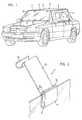
- the protective tarpaulinis shown in the assembled state.
- the actual protective tarpaulin 2is carried by a mounting system, the latter being essentially held on the car windows.
- a mounting element 1is placed on each window pane.
- These support elements 1serve to support two rods 4 running laterally in the horizontal direction above the roof and laterally parallel to the longitudinal direction of the vehicle.
- These rods 4prevent the tarpaulin 2 from resting on the vehicle roof or body and stabilize the tarpaulin in the event of wind movements.
- the tarpaulin 2is supported indirectly via these rods 4.
- the latterare preferably designed as telescopic rods.
- the length of the rodswhich consist of two or more sections, can be fixed in a conventional manner after adjustment of the length, for example with expansion sleeves.
- the protective tarpaulin, or its lateral tab 3 for covering the window frontis stretched over this holding device 1, 4 and fastened by means of a plurality of fastening means 5.
- these fastening meansare designed as suction cups, which can be fastened to the window panes or the body by simple pressure. Instead of such suction cups, other fastening means such as, for example, elastic tensioners, hooks, etc. can be used.
- FIG. 2shows a mounting element 1 in a preferred embodiment in detail.
- the element 1consists of three functional parts, which, however, represent a part structurally. These are a fastening part 11, a support arm 12 and a holder 13.
- the holder elementis formed in one piece from a strip of plastic or metal, which is bent or angled several times.
- the one-piece design of the mounting elementenables simple and inexpensive production.
- the fastening part 11is designed here as a clamp member which is pushed in a simple manner over the slightly open pane. To protect the vehicle window and as protection against displacement, the inside of the fastening part can be coated; e.g. have a rubber covering.
- This fastening partis formed in that the one free end of the strip is given a cross-sectionally U-shaped profile by being bent twice, its web width preferably being 3 to 8 mm and the length of the legs being at least 20 mm.
- the mounting elementis bent parallel to the leg by 180 °. It is thereby achieved in an advantageous manner that the material thickness is doubled for the leg, which is primarily under pressure.
- the two parallel areasare preferably glued.
- a comb 15(shown in broken lines in FIG. 2) can be placed on the fastening part 11 or on the outside of the web of the U-profile or formed by angling. This comb corresponds to the thickness of a window pane, so that when the window is closed, the comb 15 engages in the slot on the door, which is usually provided for the window, instead of the window at the top. As a result, the fastening part is supported at the bottom against the window and at the top against the frame, so that even large loads can be borne by the mounting element.
- the support arm 12which extends obliquely upwards and laterally outwards, is provided.
- the bracket 13which is formed here by a bent part with a U-profile.
- the U-profilespreferably forming somewhat more than a semicircle in cross section (circle segment of more than 180 °)
- the rods can 4Fig. 1 inserted directly into this U-profile bracket and clamped in it.
- the mounting elementsit is possible to manufacture the mounting elements as a plastic pressed part or to connect the functional parts to one another in a conventional manner, for example to glue or screw them together.
- the fastening part 11 and the support arm 12are angled relative to one another, so that the support arm 12 is inclined by an angle ⁇ with respect to the vertical or the window pane in the assembled state, ie it projects obliquely upwards.
- This angle ⁇can also be understood as the angle between the receiving opening 9 of the fastening part 11 relative to the support arm 12.
- the length of the support arm 12 and its inclination ⁇can vary. The length is preferably chosen so that the tarpaulin lies about 5 to 10 cm above the vehicle roof.
- the lateral distance of the rods 4 from the vehicle bodycan be influenced via the inclination ⁇ be, the horizontal offset of the bracket 13 relative to the window panes is about 5 cm.
- a favorable position of the mounting elementsarises at an angle of inclination ⁇ between 30 ° to 45 °, since then the mentioned offset in the desired areas is at a relatively short length of the support arms 12, which leads to good stability, in particular also with regard to the forces, for example can occur in stronger winds.
- the support arms 12can be designed with a relatively low inclination and a great length.
- the support arm 12can also be made adjustable in length in order to be able to influence the distance between the tarpaulin and the roof.
- either two mounting elements 1can be placed next to one another on the same window pane.
- the elementscan also have a wide fastening part 11, which ensures sufficient stability of the elements.
- the holder 13is either designed to be wider or, preferably, is designed as a closed tube section into which the rod 4 can be inserted.
- the holding element 1can have a fastening part 11 which can be placed directly on the vehicle doors.
- the fastening part 11here preferably has two elastic tabs 11a, 11b, the tab 11b being angled at its free end around the upper edge 8 of the vehicle door to grasp and act as anchoring part.
- the flap 11ain turn supports the element on the outside of this edge 8. Thanks to the corresponding clamping force of the fastening part 11, the mounting element is firmly seated directly on the vehicle door.
- the protective tarpaulin 2can be made of water-repellent, possibly air-permeable material, so that when the air is heated between the tarpaulin and the car roof, it can escape better. Circulation of the air is also ensured by the fact that the tarpaulin is not in contact with the body and the roof and that there can be 3 air gaps between transitions between the side tabs.
- the tarpaulincan also have a reflective coating to ensure additional heat protection.
- the shape of the tarpaulincan vary widely. For example, the lateral parts that are stretched down over the windows can be designed so that they overlap one another, i.e. there are no more air gaps.
- the protective tarpaulincan be attached directly to the mounting elements 1 and to dispense with the rods 4.
- the tarpaulincan be reinforced by sewn-in plastic struts or struts that can be pushed into sewn-in tabs.
- conventional rodssuch as e.g. known for tents can be used.
- the side rodsare formed by two separate sections. Each rod section 6 is held by an associated mounting element (1). A forward and a rearward projecting section is provided on each side. In order to the tarpaulin is well stabilized in the longitudinal direction. In order to be able to absorb the lever forces occurring due to the one-sided fastening of the rod sections, it is possible to provide at least one additional support strut 7 per rod section 6. This is, for example, as shown in Figure 4, articulated at a distance from the mounting element with the rod section 6 and supports this against the mounting element in which the support strut 7 can be hung.
- brackets (13) of the bracket elements (1)are preferably designed in the form already described as a tubular section, into each of which a rod section 6 is inserted and possibly fixed with a wing screw.
- the brackets (13)can have a stop so that the rod sections come into a defined position after insertion or a through opening can be provided so that the rod sections can be moved in the direction of the front or rear window, depending on the vehicle model.
- the tarpWhen not in use, the tarp can be folded up in a small space and the rods 4 pushed together or taken apart.
- the support elements 1can also be stowed in a very small space, so that the protective tarpaulin and its device for fastening can be easily accommodated in the luggage compartment of the vehicle.
- the mounting elements according to the inventioncan also be used in connection with vehicles for purposes other than for fastening a car tarpaulin.
- Your advantageis an extremely simple assembly and disassembly without additional screws etc. So you can of course Attachment of a simple sheet for the front window (anti-icing protection) can be used or can be used as holders for other car accessories, in which case the holder (13) is designed as required; for example as an eyelet or hook.
Landscapes
- Engineering & Computer Science (AREA)
- Mechanical Engineering (AREA)
- Body Structure For Vehicles (AREA)
- Window Of Vehicle (AREA)
- Vehicle Interior And Exterior Ornaments, Soundproofing, And Insulation (AREA)
- Soil Working Implements (AREA)
- Tents Or Canopies (AREA)
- Power-Operated Mechanisms For Wings (AREA)
Abstract
Description
Translated fromGermanDie Erfindung bezieht sich auf ein Halterungselement gemäss Patentanspruch 1 und eine Vorrichtung zur Befestigung einer Autoschutzplane gemäss Patentanspruch 7.The invention relates to a mounting element according to
Autoschutzplanen werden für verschiedenste Zwecke eingesetzt, wobei namentlich deren Funktion als Sonnenschutz, als Schutz gegen Vereisungen oder aber als Schutz gegen Ablagerung von Verschmutzungen auf dem Fahrzeug im Vordergrund steht. Derartige Schutzplanen haben in verschiedener Hinsicht der Anforderung nach Flexibilität und einfacher Handhabung zu genügen. Es wird nicht nur verlangt, dass verschiedenste Automodelle mit einer entsprechenden Vorrichtung ausgerüstet werden können, sondern ebenso wichtig ist eine einfache Montage und Demontage, wobei dies um so mehr im Vordergrund steht, wenn eine Verwendung der Schutzplane als Sonnenschutz oder Vereisungsschutz erfolgt, wird doch dann oft eine tägliche Montage bzw. Demontage erforderlich.Car tarpaulins are used for a wide variety of purposes, with their function as sun protection, as protection against icing or as protection against the accumulation of dirt on the vehicle. Protection tarpaulins of this kind have to meet the requirement for flexibility and simple handling in various respects. It is not only required that a wide variety of car models can be equipped with a corresponding device, but simple assembly and disassembly is just as important, which is all the more important if the protective tarpaulin is used as sun protection or icing protection often daily assembly or disassembly required.
Aus dem Schweizer Patent Nr. 601 039 ist beispielsweise eine Vorrichtung zum Schutz des Wageninnenraumes bekannt, die einen her kömmlichen Gepäckträgern entsprechenden Aufbau auf dem Wagendach aufweist. An diesem Aufbau sind mehrere seitliche Planen vorgesehen, welche je nach Bedarf heruntergefaltet werden oder bei Nichtgebrauch auf diesen Aufbau gelegt werden. Eine andere Vorrichtung gemäss dem Schweizer Patent Nr. 668 398 verwendet einen an den Regenrinnen im Bereich der Dachvorderkante fixierten Bügel an dem ein Rouleau drehbar gelagert ist und nach Bedarf über die Windschutzscheibe heruntergezogen werden kann. Das Rouleau wird entweder unter die Scheibenwischer geklemmt oder mit mechanischen Mitteln oder Magneten befestigt. Im praktischen Einsatz sind diese und ähnliche Vorrichtungen nur beschränkt tauglich. Es erweist sich, dass diese Vorrichtungen während der Fahrt grundsätzlich demontiert werden müssen, da sie entweder den Einsatz eines eigentlichen Gepackträgers verunmöglichen und andererseits, insbesondere bei der Vorrichtung gemass dem Schweizer Patent Nr. 601 039, zusätzliche Vorkehrungen getroffen werden müssten um die Planen gegen den Fahrtwind zu fixieren. Ein grosser Nachteil besteht darin, dass die Vorrichtungen an den seitlich am Dach verlaufenden Regenrinnen befestigt werden müssen. Solche Regenrinnen sind aber nicht bei allen Fahrzeugtypen vorhanden, was insbesondere bei neueren Modellen häufig der Fall ist, so dass bei einer Vielzahl von Autos die herkömmlichen Vorrichtungen gar nicht eingesetzt werden können. Zudem besteht der Nachteil, dass diese Vorrichtungen (wie Dachgepäckträger) den jeweiligen Dimensionen der verschiedenen Fahrzeugtypen angepasst sein müssen, was eine aufwendigere Produktion erfordert und beim Abnehmer bei einem Wechsel des Fahrzeugs die Weiterverwendung einer solchen Schutzvorrichtung oft nicht mehr erlaubt. Beim Nichtgebrauch müssen die sperrigen Vorrichtungen abgenommen werden und oft, bspw. auf Reisen, im Gepäckraum des Fahrzeugs untergebracht werden.For example, a device for protecting the interior of a car is known from Swiss Patent No. 601 039 Conventional porters have the appropriate structure on the roof. Several side tarpaulins are provided on this structure, which can be folded down as required or placed on this structure when not in use. Another device according to Swiss Patent No. 668 398 uses a bracket fixed to the gutters in the area of the front edge of the roof, on which a roller is rotatably mounted and can be pulled down over the windshield as required. The blind is either clamped under the windshield wipers or fastened with mechanical means or magnets. In practical use, these and similar devices are only of limited use. It turns out that these devices must always be dismantled while driving, since they either make it impossible to use an actual luggage rack and, on the other hand, especially with the device according to Swiss Patent No. 601 039, additional precautions would have to be taken to prevent the tarpaulin against the Fix the airstream. A major disadvantage is that the devices have to be attached to the rain gutters running on the side of the roof. Such gutters are not available in all vehicle types, which is often the case, in particular, in newer models, so that the conventional devices cannot be used in a large number of cars. In addition, there is the disadvantage that these devices (such as roof racks) have to be adapted to the respective dimensions of the different vehicle types, which requires more complex production and often does not allow the customer to continue using such a protective device when changing the vehicle. When not in use, the bulky devices must be removed and often stored in the luggage compartment of the vehicle, for example when traveling.
Aus der US-A-2 770 244 ist auch eine Vorrichtung gemäß dem Oberbegriff des Anspruchs 1 zum Befestigen eines trag baren Ankleideraumes an einer Fahrzeugtüre bekannt. Die Befestigung am Fahrzeug geschieht über ein Halterungselement, das sich über zwei Befestigungsteile an zwei Stellen am Innenrand einer Fensteröffnung in der Fahrzeugtüre abstützt. Die beiden Befestigungsteile stützen einen Tragarm ab, an dem der Ankleidraum befestigt ist. Aus der FR-A-1 332 703 ist weiter eine Schutzabdeckung für die Fenster eines Autos bekannt, die über Hacken an der Regenrinne oder am Türrahmen sowie über Saugnäpfe an den Fensterscheiben befestigt werden kann.From US-A-2 770 244 a device according to the preamble of
Bei den letztgenannten beiden Vorrichtungen ist die Befestigung am Fahrzeug derart ausgebildet, dass mehrere Befestigungsstellen für eine Vorrichtung notwendig sind. Damit wird aber die Montage der Vorrichtung am Fahrzeug kompliziert und zeitaufwendig. Zudem haben alle diese Vorrichtungen den Nachteil, dass sie sich für die Verwendung an Cabriolets, insbesondere bei geöffnetem Dach nicht eignen, da die Befestigungsstellen teils ein festes Dach oder feste Fensterausschnitte oder feste Türrahmen voraussetzen.In the latter two devices, the attachment to the vehicle is designed in such a way that several attachment points are required for one device. However, this makes the assembly of the device on the vehicle complicated and time-consuming. In addition, all of these devices have the disadvantage that they are not suitable for use on convertibles, in particular when the roof is open, since the fastening points sometimes require a fixed roof or fixed window cutouts or fixed door frames.
Es ist deshalb Aufgabe der vorliegenden Erfindung, ein Halterungselement und eine Vorrichtung insbesondere zur Befestigung einer Autoschutzplane zu schaffen, welche die oben erwähnten Nachteile vermeidet und insbesondere eine einfache und schnelle Montage und Demontage gewährleistet, bei Nichtgebrauch eine Verpackung auf kleinem Raum zulässt, an verschiedenste Automodelle angepasst werden kann, dabei einfach und kostengünstig in der Herstellung ist und auch zusammen mit Dachgepäckträgern verwendet werden kann.It is therefore an object of the present invention to provide a mounting element and a device, in particular for fastening a To create car tarpaulin, which avoids the disadvantages mentioned above and in particular ensures simple and quick assembly and disassembly, allows packaging in a small space when not in use, can be adapted to a wide variety of car models, is simple and inexpensive to manufacture and also together with roof racks can be used.
Diese Aufgabe wird durch die in Patentansprüchen 1 und 7 genannten Merkmale gelöst.This object is achieved by the features mentioned in
Anhand der beiden beiliegenden Figuren soll ein Ausführungsbeispiel der Erfindung näher erläutert werden.
- Fig. 1
- zeigt erfindungsgemäss eine Autoschutzplane zusammen mit der Befestigungsvorrichtung in montiertem Zustand
- Fig. 2
- zeigt ein erfindungsgemässes Halterungselement, aufgesetzt auf eine Autoscheibe
- Fig. 3
- zeigt ein anderes Ausführungsbeispiel des Halterungselements, aufgesetzt auf der obere Türkante
- Fig. 4
- zeigt ein Halterungselement mit Stangenabschnitt und Stützstrebe
- Fig. 1
- shows according to the invention a car tarpaulin together with the fastening device in the assembled state
- Fig. 2
- shows a mounting element according to the invention, placed on a car window
- Fig. 3
- shows another embodiment of the bracket element, placed on the upper door edge
- Fig. 4
- shows a support member with rod section and support strut
In der folgenden Beschreibung wird insbesondere auf eine Autosonnenschutzplane Bezug genommen. Die entsprechenden Ausführungen gelten jedoch in entsprechender Weise auch für Schutzplanen mit anderen Funktionen, wobei je nach Bedarf die Halterung, Befestigung und Material für die Plane variiert werden können.In the following description, reference is made in particular to a car sun protection tarpaulin. However, the corresponding statements apply in a corresponding manner to protective tarpaulins with other functions, whereby the holder, fastening and material for the tarpaulin can be varied as required.
In Figur 1 ist die Schutzplane in montiertem Zustand dargestellt. Die eigentliche Schutzplane 2 wird durch ein Halterungssystem getragen, welches letztere im wesentlichen an den Autoscheiben gehaltert ist. Dazu wird - im dargestellten Fall mit einem Fahrzeug mit vier Fenstern, die je geöffnet werden können - an jeder Fensterscheibe ein Halterungselement 1 aufgesetzt. Diese Halterungselemente 1 dienen der Auflage von zwei seitlich in horizontaler Richtung über dem Dach und seitlich von diesem parallel zur Fahrzeuglängsrichtung verlaufenden Stangen 4. Diese Stangen 4 verhindern ein Aufliegen der Plane 2 auf dem Fahrzeugdach bzw. der Karosserie und stabilisiert die Plane bei Windbewegungen. Die Plane 2 wird diesfalls indirekt über diese Stangen 4 abgestützt. Letztere sind vorzugsweise als teleskopartig ausziehbare Stangen ausgebildet. Dies ermöglicht eine problemlose Anpassung an verschiedene Längen von Fahrzeuginnenräumen indem die Stangen 4 so weit ausgezogen werden, dass deren Enden in den Bereich über der Front- bzw. Heckscheibe zu liegen kommen. In ihrer Länge können die Stangen, die aus zwei oder mehr Abschnitten bestehen, nach Einstellung der Länge in herkömmlicher Weise, bspw. mit Spreizhülsen, fixiert werden. Über diese Halterungsvorrichtung 1, 4 ist die Schutzplane, bzw. deren seitlichen Lappen 3 zur Abdeckung der Fensterfront, gespannt und mittels mehreren Befestigungsmitteln 5 festgemacht. In einer vorzugsweisen Ausführungsform sind diese Befestigungsmittel als Saugnäpfe ausgebildet, die durch einfachen Druck an den Fensterscheiben oder der Karosserie befestigt werden können. Anstelle solcher Saugnäpfe können andere Befestigungsmittel wie bspw. elastische Spanner, Haken, etc. zur Verwendung kommen.In Figure 1, the protective tarpaulin is shown in the assembled state. The actual
In Figur 2 ist ein Halterungselement 1 in einer bevorzugten Ausführungsform detailliert dargestellt. Im wesentlichen besteht das Element 1 aus drei funktionellen Teilen, die jedoch konstruktiv vorzugsweise einen Teil darstellen. Es sind dies ein Befestigungsteil 11, ein Tragarm 12 und eine Halterung 13. Vorliegend ist das Halterungselement einstückig aus einem Streifen aus Kunststoff oder Metall gebildet, der mehrmals gebeugt oder abgewinkelt ist. Die einstückige Ausgestaltung des Halterungselementes ermöglicht eine einfache und kostengünstige Herstellung. Der Befestigungsteil 11 ist hier als Klammerorgan ausgebildet, das in einfacher Weise über die leicht geöffnete Scheibe geschoben wird. Zum Schutz der Fahrzeugscheibe sowie als Absicherung gegen ein Verschieben kann die Innenseite des Befestigungsteils beschichtet sein; z.B. einen Gummibelag aufweisen. Dieser Befestigungsteil wird dadurch gebildet, dass das eine freie Ende des Streifens durch zweifaches Abwinkeln ein im Querschnitt U-förmiges Profil erhält, wobei dessen Stegbreite vorzugsweise 3 bis 8 mm und die Länge der Schenkel mindestens 20 mm beträgt. An der Scheibenaussenseite ist das Halterungselement parallel zum Schenkel um 180° abgebogen. Es wird dadurch in vorteilhafter Weise erreicht, dass die Materialstärke bei dem Schenkel, der vor allem druckbelastet ist, verdoppelt wird. Die beiden parallellaufenden Bereiche sind vorzugsweise verklebt.FIG. 2 shows a
Beim Schliessen der Scheibe wird das Halterungselement fixiert, wobei das Fenster im allgemeinen bis auf einen Spalt von ca. 5 mm (abhängig von der Materialstärke des Elements) geschlossen wird. Dadurch ist eine minimale Belüftung des Fahrzeugraumes gewährleistet. Die Einbruchssicherheit des Fahrzeugs ist nicht tangiert. Soll in speziellen Anwendungen eine besonders stabile Montage des Halterungselementes erreicht werden, so kann auf dem Befestigungsteil 11, bzw. auf der Aussenseite des Steges des U-Profils, ein Kamm 15 (gestrichelt in Figur 2 dargestellt) aufgesetzt oder durch Abwinklung gebildet sein. Dieser Kamm entspricht der Dicke einer Fensterscheibe, so dass beim Schliessen des Fensters der Kamm 15 anstelle des Fensters oben in den üblicherweise für das Fenster vorgesehenen Schlitz an der Türe eingreift. Dadurch wird der Befestigungsteil unten gegen das Fenster und oben gegen den Rahmen abgestützt, so dass auch grosse Belastungen durch das Halterungselement getragen werden können.When the window is closed, the holding element is fixed, the window generally being closed to a gap of approximately 5 mm (depending on the material thickness of the element). This ensures minimal ventilation in the vehicle compartment. The vehicle's security against burglary is not affected. If, in special applications, a particularly stable mounting of the mounting element is to be achieved, a comb 15 (shown in broken lines in FIG. 2) can be placed on the
Damit die Plane in einem Abstand von der Karosserie und insbesondere vom Fahrzeugdach gehalten wird, ist der schräg nach oben und seitlich nach aussen verlaufender Tragarm 12 vorgesehen. An seinem freien Ende befindet sich die Halterung 13, die hier durch einen abgebogenen Teil mit U-Profil gebildet wird. Sofern für die Halterungselemente 1 bzw. die Halterungen 13 ein Material mit elastischen Eigenschaften verwendet wird, bspw. Polyvinylchlorid oder Polycarbonat, wobei die U-Profile vorzugsweise im Querschnitt etwas mehr als einen Halbkreis bilden (Kreissegment von mehr als 180°), können die Stangen 4 (Fig. 1) direkt in diese U-Profil-Halterung eingesetzt und darin festgeklemmt werden. Selbstverständlich ist es möglich, die Halterungselemente als Kunststoffpressteil herzustellen oder die funktionellen Teile in herkömmlicher Weise miteinander zu verbinden, bspw. zu verkleben oder zu verschrauben.So that the tarpaulin is held at a distance from the body and in particular from the vehicle roof, the
Der Befestigungsteil 11 und der Tragarm 12 sind gegeneinander abgewinkelt, so dass der Tragarm 12 im montierten Zustand bezüglich der Vertikalen bzw. der Fensterscheibe um einen Winkel α geneigt ist, d.h. schräg nach oben ragt. Dieser Winkel α kann auch verstanden werden als Winkel zwischen der Aufnahmeöffnung 9 des Befestigungsteils 11 gegenüber dem Tragarm 12. Die Länge des Tragarmes 12 und dessen Neigung α kann variieren. Vorzugsweise wird die Länge so gewählt, dass die Plane ca. 5 bis 10 cm über das Fahrzeugdach zu liegen kommt. Über die Neigung α kann der seitliche Abstand der Stangen 4 gegenüber der Fahrzeugkarosserie beeinflusst werden, wobei der horizontale Versatz der Halterung 13 gegenüber den Fensterscheiben ca. 5 cm beträgt. Eine günstige Lage der Halterungselemente entsteht bei einem Neigungswinkel α zwischen 30° bis 45°, da dann der erwähnte Versatz in den erwünschten Bereichen liegt bei relativ geringer Länge der Tragarme 12, was zu einer guten Stabilität führt, insbesondere auch hinsichtlich der Kräfte, die z.B. bei stärkerem Wind auftreten können. Um die Verwendung der Vorrichtung auch im Zusammenhang mit montierten Dachgepäckträgern zu gewährleisten, können die Tragarme 12 mit einer relativ geringen Neigung und einer grossen Länge ausgebildet werden. In einer speziellen Ausführungsform kann auch der Tragarm 12 in seiner Länge verstellbar ausgebildet sein um den Abstand zwischen Plane und Dach beeinflussen zu können.The
Sofern die Vorrichtung für Fahrzeuge mit nur zwei absenkbaren Fensterscheiben verwendet werden soll, können entweder zwei Halterungselemente 1 nebeneinander auf die gleiche Fensterscheibe aufgesetzt werden. Oder es können hier die Elemente auch einen breiten Befestigungsteil 11 aufweisen, der eine genügende Stabilität der Elemente gewährleistet. In gleicher Weise wird auch die Halterung 13 entweder breiter ausgelegt oder aber vorzugsweise als geschlossener Rohrabschnitt ausgebildet, in welchen die Stange 4 eingeschoben werden kann.If the device is to be used for vehicles with only two lowerable window panes, either two mounting
In einer weiteren Ausbildungsform gemäss Figur 3 kannen das Halterungselement 1 einen Befestigungsteil 11 aufweisen, der direkt auf die Fahrzeugtüren aufgesetzt werden können. Auf diese Weise besteht die Möglichkeit, die Halterungselemente derart zu befestigen, dass die Fenster nicht tangiert sind und demnach vollständig geschlossen werden können. Der Befestigungsteil 11 weist hier vorzugsweise zwei elastische Lappen 11a, 11b auf, wobei der Lappen 11b an seinem freien Ende abgewinkelt ist um die obere Kante 8 der Fahrzeugtüre zu umgreifen und so als Verankerungsteil zu wirken. Der Lappen 11a stützt seinerseits das Element an der Aussenseite dieser Kante 8 ab. Dank der entsprechenden Spannkraft des Befestigungsteils 11 sitzt das Halterungselement fest, direkt auf der Fahrzeugtüre.In a further embodiment according to FIG. 3, the holding
Die Schutzplane 2 kann aus wasserabstossendem, evt. luftdurchlässigem Material gefertigt sein, damit bei Erhitzen der Luft zwischen Plane und Autodach diese besser entweichen kann. Eine Umwälzung der Luft ist aber auch dadurch gewährleistet, dass die Plane nicht an der Karosserie und dem Dach anliegt und jeweils zwischen Übergängen zwischen den seitlichen Lappen 3 Luftspalte bestehen können. Die Plane kann auch reflektierend beschichtet sein, um eine zusätzlichen Wärmeschutz zu gewährleisten. Die Schutzplane kann in ihrer Form in weiten Bereichen variieren. So können bspw. deren seitlichen Teile, die über die Fenster hinabgespannt werden, so ausgebildet werden, dass sie sich gegenseitig überlappen, d.h. keine Luftspalten mehr bestehen.The
Selbstverständlich ist es auch möglich, die Schutzplane direkt an den Halterungselementen 1 zu befestigen und auf die Stangen 4 zu verzichten. Diesfalls kann die Plane durch eingenähte Kunststoffstreben oder in eingenähte Laschen schiebbare Streben verstärkt sein. Für diese Streben können herkömmliche Stangen, wie sie z.B. für Zelte bekannt sind, verwendet werden.Of course, it is also possible to attach the protective tarpaulin directly to the mounting
Eine weitere bevorzugte Ausführungsform wird dadurch erreicht, dass die seitlichen Stangen durch zwei separate Abschnitte gebildet werden. Jeder Stangenabschnitt 6 ist je durch ein zugehöriges Halterungselement (1) gehalten. Dabei ist an jeder Seite ein nach vorne und ein nach hinten ragender Abschnitt vorgesehen. Damit wird die Plane in Längsrichtung gut stabilisiert. Um die wegen der einseitigen Befestigung der Stangenabschnitte auftretenden Hebelkräfte auffangen zu können, ist es möglich, mindestens eine zusätzliche Stützstrebe 7 pro Stangenabschnitt 6 vorzusehen. Diese ist z.B., wie in Figur 4 dargestellt, im Abstand vom Halterungselement gelenkig mit dem Stangenabschnitt 6 verbunden und stützt diesen gegen das Halterungselement ab, in welchem die Stützstrebe 7 eingehängt werden kann. Diese Ausführungsform hat den Vorteil, dass (nach Hinaufklappen eines seitlichen Abschnitts der Plane) die Seitentüren einzeln geöffnet werden können, ohne dass die Befestigungsvorrichtungen demontiert oder entfernt werden müssen. In diesem Falle sind die Halterungen (13) der Halterungselemente (1) vorzugsweise in bereits beschriebener Form als Rohrabschnitt ausgebildet in die je ein Stangenabschnitt 6 eingeschoben und allenfalls mit einer Flügelschraube fixiert wird. Die Halterungen (13) können einen Anschlag aufweisen, so dass die Stangenabschnitte nach dem Einsetzen in eine definierte Lage kommen oder es kann eine durchgehende Öffnung vorgesehen sein, so dass die Stangenabschnitte je nach Fahrzeugmodell in Richtung der Front- oder Heckscheibe verschoben werden können.Another preferred embodiment is achieved in that the side rods are formed by two separate sections. Each
Bei Nichtgebrauch kann die Plane auf kleinem Raum zusammengelegt und die Stangen 4 zusammengeschoben bzw. zerlegt werden. Die Halterungselemente 1 sind ebenfalls auf sehr kleinem Raum verstaubar, so dass sich die Schutzplane sowie deren Vorrichtung zur Befestigung leicht im Gepäckraum des Fahrzeuges unterbringen lassen.When not in use, the tarp can be folded up in a small space and the rods 4 pushed together or taken apart. The
Es ist zu bemerken, dass die erfindungsgemässen Halterungselemente im Zusammenhang mit Fahrzeugen auch zu anderen Zwecken als zur Befestigung einer Autoschutzplane eingesetzt werden können. Ihr Vorzug besteht in einer äusserst einfachen Montage bzw. Demontage ohne zusätzliche Schrauben etc. So können sie selbstverständlich zur Befestigung einer einfachen Blache für die Frontscheibe (Vereisungsschutz) eingesetzt werden oder als Halterungen für andere Autozubehörteile verwendet werden, wobei dann die Halterung (13) je nach Bedarf ausgestaltet ist; bspw. als Öse oder Haken.It should be noted that the mounting elements according to the invention can also be used in connection with vehicles for purposes other than for fastening a car tarpaulin. Your advantage is an extremely simple assembly and disassembly without additional screws etc. So you can of course Attachment of a simple sheet for the front window (anti-icing protection) can be used or can be used as holders for other car accessories, in which case the holder (13) is designed as required; for example as an eyelet or hook.
Claims (11)
- Holding element (1) for fitting an accessory to a vehicle body, with a mounting (13), a fixing part (11) and a bracket (12) connecting the same for producing a vertical and horizontal spacing of the mounting (13) with respect to the vehicle body, characterized in that the fixing part (11) is constructed in such a way that it is supported on the window pane or on the upper edge (8) of a vehicle door.
- Holding element according to claim 1, characterized in that the holding element (1) is made in one piece from a multiply bent or angled plastic or metal strip, one free end of the strip by double bending has a cross-sectionally U-shaped profile as the fixing part (11), whose web width is 3 to 8 mm and whereof the leg length is at least 20 mm, whilst the other free end of the strip is bent to form a mounting (13) forming in cross-section a circular segment of at least 180°.
- Holding element according to claim 1, characterized in that the holding element (1) has a fixing part (11) with two spaced tabs (11a, 11b) for fixing to the upper vehicle door edge (8).
- Holding element according to claim 1 or 2, characterized in that the fixing part (11) has a ridge (15).
- Holding element according to one of the preceding claims, characterized in that the mounting (13) is designed as a tubular portion for receiving a rod (4).
- Holding element according to one of the preceding claims, characterized in that the fixing part (11) and the bracket (12) are so angled against one another that the reception opening (9) of the fixing part (11) forms with the bracket (12) an angle (α) of 30 to 45°.
- Apparatus for fixing a car awning with a holding element according to claim 1, characterized in that at least two holding elements (1) mountable on the window panes or the upper edge of a vehicle door are provided as direct or indirect support points for a protective awning (2).
- Apparatus according to claim 7, characterized in that two length-adjustable rods are inserted in in each case at least one of the mountings (13) of the fitted holding elements (1) parallel to the direction of travel and spaced from the body in order to stabilize the awning (2).
- Apparatus according to one of the claims 7 or 8, characterized in that in each case at least two holding elements (1) are provided with mountings (13), constructed as tubular portions, for each vehicle side and that in each mounting is in each case inserted one associated rod portion (6).
- Apparatus according to claim 9, characterized in that for each rod portion (6) is provided a support strut (7), which supports the rod portion against the holding element (1).
- Apparatus according to one of the claims 7 to 10, characterized in that the portions of the awning, which are intended for covering the window, in each case have at least one suction cup (5) for fixing to the windows or the body.
Applications Claiming Priority (2)
| Application Number | Priority Date | Filing Date | Title |
|---|---|---|---|
| CH149789 | 1989-04-19 | ||
| CH1497/89 | 1989-04-19 |
Publications (3)
| Publication Number | Publication Date |
|---|---|
| EP0394190A2 EP0394190A2 (en) | 1990-10-24 |
| EP0394190A3 EP0394190A3 (en) | 1991-04-24 |
| EP0394190B1true EP0394190B1 (en) | 1993-11-10 |
Family
ID=4211836
Family Applications (1)
| Application Number | Title | Priority Date | Filing Date |
|---|---|---|---|
| EP90810266AExpired - LifetimeEP0394190B1 (en) | 1989-04-19 | 1990-04-03 | Holding device and arrangement for the fixing of a motorcar awning |
Country Status (5)
| Country | Link |
|---|---|
| EP (1) | EP0394190B1 (en) |
| AT (1) | ATE97065T1 (en) |
| DE (1) | DE59003401D1 (en) |
| DK (1) | DK0394190T3 (en) |
| ES (1) | ES2048476T3 (en) |
Families Citing this family (5)
| Publication number | Priority date | Publication date | Assignee | Title |
|---|---|---|---|---|
| GB2271328A (en)* | 1992-10-09 | 1994-04-13 | Milton Berry | Vehicle shelter |
| DE10316592A1 (en)* | 2003-04-11 | 2004-10-28 | Daimlerchrysler Ag | Retractable protective awning and motor vehicle with protective awning |
| US8096338B2 (en)* | 2009-09-25 | 2012-01-17 | Michael Alan Postill | Method and apparatus for applying sheet material to a vehicle |
| CN103381749B (en)* | 2013-07-12 | 2015-07-29 | 长兴泗安科林植保专业合作社 | A vehicle-mounted sunshade fixing seat |
| CN103381750A (en)* | 2013-07-12 | 2013-11-06 | 长兴泗安科林植保专业合作社 | Vehicle-mounted sunshade |
Family Cites Families (5)
| Publication number | Priority date | Publication date | Assignee | Title |
|---|---|---|---|---|
| US2770244A (en)* | 1954-10-20 | 1956-11-13 | Carson Nathan | Portable dressing room |
| FR1332703A (en)* | 1962-06-07 | 1963-07-19 | Protective cover for automotive glass | |
| BE695125A (en)* | 1967-03-07 | 1967-08-14 | ||
| CH601039A5 (en)* | 1976-06-29 | 1978-06-30 | Paul Ledermann | Passenger compartment protector for vehicles parked outside |
| CH668398A5 (en)* | 1986-01-20 | 1988-12-30 | Reinhard Steiner Wirz | Anti-icing cover for vehicle windscreens - has plastics roller blind fitted to roof rack across bar above windscreen |
- 1990
- 1990-04-03ATAT90810266Tpatent/ATE97065T1/ennot_activeIP Right Cessation
- 1990-04-03EPEP90810266Apatent/EP0394190B1/ennot_activeExpired - Lifetime
- 1990-04-03ESES90810266Tpatent/ES2048476T3/ennot_activeExpired - Lifetime
- 1990-04-03DEDE90810266Tpatent/DE59003401D1/ennot_activeExpired - Fee Related
- 1990-04-03DKDK90810266.8Tpatent/DK0394190T3/enactive
Also Published As
| Publication number | Publication date |
|---|---|
| EP0394190A3 (en) | 1991-04-24 |
| DE59003401D1 (en) | 1993-12-16 |
| EP0394190A2 (en) | 1990-10-24 |
| DK0394190T3 (en) | 1994-02-07 |
| ES2048476T3 (en) | 1994-03-16 |
| ATE97065T1 (en) | 1993-11-15 |
Similar Documents
| Publication | Publication Date | Title |
|---|---|---|
| DE2753076C2 (en) | Weather protection arrangement for road vehicles | |
| EP1068100B1 (en) | Storage facility for a motor vehicle and segmentation device | |
| EP2353904B1 (en) | Side curtain for a commercial vehicle structure | |
| DE19914427C2 (en) | Motor vehicle roof | |
| DE4404619A1 (en) | Off-road vehicle with a two-part roof structure | |
| DE19536552A1 (en) | Wind deflector for a convertible with at least one roll bar | |
| DE102008006157A1 (en) | Rear wind screen for two-seat automobile has slide-fit roller blind stabilised at sides | |
| DE19930136C1 (en) | Divider to separate the luggage stowage area of an estate car from the passenger zone is a roller blind netting with a draw bar held in a positive fit in a hollow chamber across the netting width | |
| EP0394190B1 (en) | Holding device and arrangement for the fixing of a motorcar awning | |
| EP0618101B1 (en) | Sealing arrangement for a preferably frameless window pane of a motor vehicle | |
| DE69500336T2 (en) | Luggage carriers for motor vehicles | |
| DE19729164A1 (en) | Rain deflector for motor vehicle windscreen | |
| DE4014057C1 (en) | Sun blind for vehicle window - has pair of profiled strips between which blind is folded | |
| DE102008020542A1 (en) | Sun visor device for the window pane of a motor vehicle and motor vehicle with such a sun visor device | |
| DE102013008910B4 (en) | Rear spoiler device for a vehicle and method for adjusting it | |
| DE2839557A1 (en) | Exterior sun blind for car - is mounted at side of roof to pull out with self-supporting braces over side of car | |
| DE19925226C2 (en) | darkening system | |
| DE4422285A1 (en) | Device for covering the outside of motor-vehicle windows | |
| DE3107001A1 (en) | Carrying device for attaching to the roof of a vehicle, in particular a passenger vehicle | |
| DE8618733U1 (en) | Motor vehicle with a sunroof | |
| DE19513820A1 (en) | Automobile accessory sun and rain protection roof | |
| DE4314889A1 (en) | Sun blind for motor vehicle | |
| DE19728908A1 (en) | Sunscreen unit for window of motor vehicle | |
| AT398946B (en) | Device for covering vehicles | |
| DE9007102U1 (en) | Weather protection for motor vehicles through roller blinds with foldable side panels |
Legal Events
| Date | Code | Title | Description |
|---|---|---|---|
| PUAI | Public reference made under article 153(3) epc to a published international application that has entered the european phase | Free format text:ORIGINAL CODE: 0009012 | |
| AK | Designated contracting states | Kind code of ref document:A2 Designated state(s):AT BE CH DE DK ES FR GB GR IT LI LU NL SE | |
| PUAL | Search report despatched | Free format text:ORIGINAL CODE: 0009013 | |
| AK | Designated contracting states | Kind code of ref document:A3 Designated state(s):AT BE CH DE DK ES FR GB GR IT LI LU NL SE | |
| 17P | Request for examination filed | Effective date:19910831 | |
| 17Q | First examination report despatched | Effective date:19920813 | |
| GRAA | (expected) grant | Free format text:ORIGINAL CODE: 0009210 | |
| ITF | It: translation for a ep patent filed | ||
| AK | Designated contracting states | Kind code of ref document:B1 Designated state(s):AT BE CH DE DK ES FR GB GR IT LI LU NL SE | |
| REF | Corresponds to: | Ref document number:97065 Country of ref document:AT Date of ref document:19931115 Kind code of ref document:T | |
| GBT | Gb: translation of ep patent filed (gb section 77(6)(a)/1977) | Effective date:19931112 | |
| REF | Corresponds to: | Ref document number:59003401 Country of ref document:DE Date of ref document:19931216 | |
| ET | Fr: translation filed | ||
| REG | Reference to a national code | Ref country code:GR Ref legal event code:FG4A Free format text:3009859 | |
| REG | Reference to a national code | Ref country code:DK Ref legal event code:T3 | |
| REG | Reference to a national code | Ref country code:ES Ref legal event code:FG2A Ref document number:2048476 Country of ref document:ES Kind code of ref document:T3 | |
| EPTA | Lu: last paid annual fee | ||
| PLBE | No opposition filed within time limit | Free format text:ORIGINAL CODE: 0009261 | |
| STAA | Information on the status of an ep patent application or granted ep patent | Free format text:STATUS: NO OPPOSITION FILED WITHIN TIME LIMIT | |
| 26N | No opposition filed | ||
| EAL | Se: european patent in force in sweden | Ref document number:90810266.8 | |
| PGFP | Annual fee paid to national office [announced via postgrant information from national office to epo] | Ref country code:SE Payment date:19990408 Year of fee payment:10 | |
| PGFP | Annual fee paid to national office [announced via postgrant information from national office to epo] | Ref country code:CH Payment date:19990412 Year of fee payment:10 | |
| PGFP | Annual fee paid to national office [announced via postgrant information from national office to epo] | Ref country code:BE Payment date:19990414 Year of fee payment:10 | |
| PGFP | Annual fee paid to national office [announced via postgrant information from national office to epo] | Ref country code:AT Payment date:19990415 Year of fee payment:10 | |
| PGFP | Annual fee paid to national office [announced via postgrant information from national office to epo] | Ref country code:ES Payment date:19990416 Year of fee payment:10 | |
| PGFP | Annual fee paid to national office [announced via postgrant information from national office to epo] | Ref country code:DK Payment date:19990426 Year of fee payment:10 Ref country code:DE Payment date:19990426 Year of fee payment:10 | |
| PGFP | Annual fee paid to national office [announced via postgrant information from national office to epo] | Ref country code:LU Payment date:19990428 Year of fee payment:10 | |
| PGFP | Annual fee paid to national office [announced via postgrant information from national office to epo] | Ref country code:NL Payment date:19990429 Year of fee payment:10 | |
| PGFP | Annual fee paid to national office [announced via postgrant information from national office to epo] | Ref country code:GR Payment date:19990430 Year of fee payment:10 Ref country code:FR Payment date:19990430 Year of fee payment:10 | |
| PG25 | Lapsed in a contracting state [announced via postgrant information from national office to epo] | Ref country code:LU Free format text:LAPSE BECAUSE OF NON-PAYMENT OF DUE FEES Effective date:20000403 Ref country code:DK Free format text:LAPSE BECAUSE OF NON-PAYMENT OF DUE FEES Effective date:20000403 Ref country code:AT Free format text:LAPSE BECAUSE OF NON-PAYMENT OF DUE FEES Effective date:20000403 | |
| PG25 | Lapsed in a contracting state [announced via postgrant information from national office to epo] | Ref country code:SE Free format text:LAPSE BECAUSE OF NON-PAYMENT OF DUE FEES Effective date:20000404 Ref country code:ES Free format text:THE PATENT HAS BEEN ANNULLED BY A DECISION OF A NATIONAL AUTHORITY Effective date:20000404 | |
| PG25 | Lapsed in a contracting state [announced via postgrant information from national office to epo] | Ref country code:LI Free format text:LAPSE BECAUSE OF NON-PAYMENT OF DUE FEES Effective date:20000430 Ref country code:GR Free format text:LAPSE BECAUSE OF NON-PAYMENT OF DUE FEES Effective date:20000430 Ref country code:CH Free format text:LAPSE BECAUSE OF NON-PAYMENT OF DUE FEES Effective date:20000430 Ref country code:BE Free format text:LAPSE BECAUSE OF NON-PAYMENT OF DUE FEES Effective date:20000430 | |
| BERE | Be: lapsed | Owner name:WITTWER WALTER Effective date:20000430 | |
| PG25 | Lapsed in a contracting state [announced via postgrant information from national office to epo] | Ref country code:NL Free format text:LAPSE BECAUSE OF NON-PAYMENT OF DUE FEES Effective date:20001101 | |
| EUG | Se: european patent has lapsed | Ref document number:90810266.8 | |
| REG | Reference to a national code | Ref country code:CH Ref legal event code:PL | |
| PG25 | Lapsed in a contracting state [announced via postgrant information from national office to epo] | Ref country code:FR Free format text:LAPSE BECAUSE OF NON-PAYMENT OF DUE FEES Effective date:20001229 | |
| NLV4 | Nl: lapsed or anulled due to non-payment of the annual fee | Effective date:20001101 | |
| REG | Reference to a national code | Ref country code:DK Ref legal event code:EBP | |
| PG25 | Lapsed in a contracting state [announced via postgrant information from national office to epo] | Ref country code:DE Free format text:LAPSE BECAUSE OF NON-PAYMENT OF DUE FEES Effective date:20010201 | |
| REG | Reference to a national code | Ref country code:FR Ref legal event code:ST | |
| PGFP | Annual fee paid to national office [announced via postgrant information from national office to epo] | Ref country code:GB Payment date:20010214 Year of fee payment:12 | |
| REG | Reference to a national code | Ref country code:GB Ref legal event code:IF02 | |
| REG | Reference to a national code | Ref country code:ES Ref legal event code:FD2A Effective date:20020204 | |
| PG25 | Lapsed in a contracting state [announced via postgrant information from national office to epo] | Ref country code:GB Free format text:LAPSE BECAUSE OF NON-PAYMENT OF DUE FEES Effective date:20020403 | |
| GBPC | Gb: european patent ceased through non-payment of renewal fee | Effective date:20020403 | |
| PG25 | Lapsed in a contracting state [announced via postgrant information from national office to epo] | Ref country code:IT Free format text:LAPSE BECAUSE OF NON-PAYMENT OF DUE FEES;WARNING: LAPSES OF ITALIAN PATENTS WITH EFFECTIVE DATE BEFORE 2007 MAY HAVE OCCURRED AT ANY TIME BEFORE 2007. THE CORRECT EFFECTIVE DATE MAY BE DIFFERENT FROM THE ONE RECORDED. Effective date:20050403 |