EP0392032B1 - Medical implantable apparatus with telematic data transmission means - Google Patents
Medical implantable apparatus with telematic data transmission meansDownload PDFInfo
- Publication number
- EP0392032B1 EP0392032B1EP89106275AEP89106275AEP0392032B1EP 0392032 B1EP0392032 B1EP 0392032B1EP 89106275 AEP89106275 AEP 89106275AEP 89106275 AEP89106275 AEP 89106275AEP 0392032 B1EP0392032 B1EP 0392032B1
- Authority
- EP
- European Patent Office
- Prior art keywords
- data
- transmission
- control logic
- logic
- state
- Prior art date
- Legal status (The legal status is an assumption and is not a legal conclusion. Google has not performed a legal analysis and makes no representation as to the accuracy of the status listed.)
- Revoked
Links
- 230000005540biological transmissionEffects0.000titleclaimsdescription57
- 230000035790physiological processes and functionsEffects0.000claimsdescription24
- 230000000638stimulationEffects0.000claimsdescription17
- 238000001514detection methodMethods0.000claimsdescription16
- 230000000694effectsEffects0.000claimsdescription7
- 230000004936stimulating effectEffects0.000claimsdescription5
- 230000000747cardiac effectEffects0.000claimsdescription3
- 125000004122cyclic groupChemical group0.000claimsdescription2
- 230000036279refractory periodEffects0.000description8
- 238000012937correctionMethods0.000description4
- 238000000034methodMethods0.000description4
- 230000008569processEffects0.000description4
- 230000003213activating effectEffects0.000description2
- 238000013461designMethods0.000description2
- 230000003993interactionEffects0.000description2
- 238000012545processingMethods0.000description2
- 230000002457bidirectional effectEffects0.000description1
- 230000015572biosynthetic processEffects0.000description1
- 230000001427coherent effectEffects0.000description1
- 238000004891communicationMethods0.000description1
- 238000010586diagramMethods0.000description1
- 238000005516engineering processMethods0.000description1
- 238000012544monitoring processMethods0.000description1
- 239000010453quartzSubstances0.000description1
- 230000003252repetitive effectEffects0.000description1
- VYPSYNLAJGMNEJ-UHFFFAOYSA-Nsilicon dioxideInorganic materialsO=[Si]=OVYPSYNLAJGMNEJ-UHFFFAOYSA-N0.000description1
- 230000002123temporal effectEffects0.000description1
Images
Classifications
- A—HUMAN NECESSITIES
- A61—MEDICAL OR VETERINARY SCIENCE; HYGIENE
- A61N—ELECTROTHERAPY; MAGNETOTHERAPY; RADIATION THERAPY; ULTRASOUND THERAPY
- A61N1/00—Electrotherapy; Circuits therefor
- A61N1/18—Applying electric currents by contact electrodes
- A61N1/32—Applying electric currents by contact electrodes alternating or intermittent currents
- A61N1/36—Applying electric currents by contact electrodes alternating or intermittent currents for stimulation
- A61N1/372—Arrangements in connection with the implantation of stimulators
- A61N1/37211—Means for communicating with stimulators
Definitions
- the inventionrelates to a medical device implantable in the body of a living being with means for detecting physiological events and / or with means for stimulating physiological processes, with control logic to which the means for detecting and / or the means for stimulating are connected, and means for telemetrically transmitting data relating to the logic state of the control logic to an external receiver, the means for transmitting data being connected to the control logic.
- the logical state of the control logicdepends, among other things. depends on whether a physiological event has been detected or a physiological process has been stimulated. If one depicts the physiological functions of the living being, with respect to which events are detected and processes are stimulated, as a function of time, for example as an electrocardiogram, and in parallel in correct chronological assignment the data relating to the logical state of the control logic, it is possible for the interaction of the device with the body of the living being. This is possible in the case of devices of the type mentioned at the outset as a result of the telemetric transmission of the data in a non-invasive way.
- a device of the type mentionedis described in EP-A-0 120 250. It is a A pacemaker that stores data relating to a previous pacemaker cycle and transmits the data to the receiver with a delay when an event occurs that completes a cycle. The data transmission takes place with a delay that corresponds to the duration of a cycle. In order to be able to display the transmitted data in correct chronological assignment to an electrocardiogram of the living being, it is therefore necessary to delay the display of the electrocardiogram, which is associated with considerable effort. In addition, the data is only transmitted once per cycle. The risk of data loss is therefore high. An effective correction of data transmission errors in the receiver is only possible to the extent that the acceptance of obviously nonsensical data can be prevented.
- the inventionhas for its object to design a device of the type mentioned in such a way that data transmission is possible with high reliability, the risk of data loss is reduced, and the prerequisite for an effective correction of data transmission errors is created.
- this objectis achieved by the features of claim 1.
- the data relating to a specific logic state of the control logiccan thus be transmitted several times, which considerably increases the reliability of the data transmission and at the same time offers the prerequisite for correcting data transmission errors.
- a delay in the data transmission compared to the respective state of the control logicis avoided.
- the data transmissioncan take place both analog and digital. In the case of analog data transmission, e.g. Frequency modulation find application.
- Each possible logic state of the control logicis then assigned a specific frequency with which the means for transmitting data modulate a carrier signal when the corresponding logic state occurs.
- a completely continuous data transmissiontakes place, whereas in the case of a digital data transmission only quasi-continuous data transmission is generally possible, which, with a sufficiently rapid sequence of the individual data transmissions, offers the same advantages as a continuous data transmission, but is less technically complex.
- a clock generatorwhich activates the means for transmitting data at continuously successive times for data transmission, wherein the means for transmitting data transmit the current data at the time of the data transmission.
- the data transmissionis again independent of detected physiological events or stimulated physiological processes, since a clock generator is provided for activating the means for transmitting data at preferably periodically successive times.
- the means for transmitting datacan be activated as often as desired by means of the clock generator. A quasi-continuous data transmission thus takes place, the means for transmitting data being activated several times during the duration of a logical state, given a suitable choice of the duration of the time intervals between successive points in time.
- the data corresponding to a certain logical stateare thus transmitted several times, so that data losses are practically impossible.
- the prerequisite for an effective correction of data transmission errorsis also created, since it is possible, for example, to design the receiver in such a way that it only accepts data that has been transmitted unchanged several times in succession.
- device cyclesaccording to a particularly advantageous variant of the invention provide for the clock generator to activate the means for transmitting data several times during a device cycle. This measure ensures that even if the logical state of the control logic changes rapidly during a device cycle the corresponding data is transmitted with high reliability. In principle, it is also conceivable for the clock generator to activate the means for transmitting data only once during a device cycle; however, this is not claimed and only makes sense if the data to be transmitted correspond to the logical states of the control logic, which generally remain unchanged over several device cycles.
- parallel data transmissionis not excluded in the context of the invention, it is provided according to a variant of the invention that the means for transmitting data transmit the data serially.
- the data transmissionis not wired, but telemetric, the technical and financial outlay for the device can be considerably reduced in this way.
- the deviceis designed as a pacemaker, the means for detecting physiological events monitoring the electrical activity of the heart and the means for stimulating physiological processes stimulating the heart.
- the means for detecting physiological eventsform an associated physiological function, in the case of a cardiac pacemaker an electrical signal corresponding to the electrical activity of the heart, which is fed to an analog / digital converter. whose digital output signal is fed to the means for transmitting data, which transmit this to the receiver.
- the device according to the inventioncan be used to obtain data corresponding to the physiological function in a simple manner, in the case of a pacemaker an intracardiac electrogram (IEKG), and transmit it to the receiver.
- the means for transmitting dataare supplied with further data relating to the operating state of the device, which transmit the means for transmitting data to the receiver. On the basis of such data, it is easily possible to check the correct technical function of the implanted device.
- the means for transmitting datainclude both the data corresponding to the logical state of the control logic and the digital output signals of the analog / digital converter or the data relating to the operating state of the device in the form of a single one Transmit data word, wherein a coherent bit sequence of the data word contains the data corresponding to the logical state of the control logic and the digital output signals of the analog / digital converter.
- This measureensures that the correct temporal assignment of the signals corresponding to the logical state of the control logic to the signal corresponding to the electrical activity of the heart, that is, for. B. the IEKG, is guaranteed without any special measures during the transmission of the data.
- FIG. 1shows a cardiac pacemaker, designated as a whole by (1), which operates in VVI mode. Accordingly, the pacemaker (1) is connected to the heart (2) via an electrode (3) inserted into the ventricle of a schematically indicated heart (2) of a living being.
- the electrode (3)serves on the one hand to detect a signal corresponding to the electrical activity of the heart (2) and to supply it to the pacemaker (1).
- the signalarrives at a schematically indicated detector circuit (4), in which the signal passes through an EKG filter (4a) and an amplifier (4b) and is fed to a level measuring unit (4c) which, when an event occurs with a natural heartbeat corresponding minimum amplitude and / or a certain steepness typical of natural heartbeats in the output signal of the amplifier (4c) emits a digital signal indicating the detection of a natural heartbeat.
- the output of the detector circuit (4)is connected to an input (5) of a control logic (6) which, based on the digital signals coming in from the detector circuit (4) and using stored data, decides whether and when there is a stimulation of the heart (2) should. If stimulation of the heart (2) is required, the control logic (6) outputs an output (7) at the appropriate time to a signal to a stimulation pulse generator (8) which is used to generate a stimulation pulse of a certain amplitude and duration.
- the electrode (3)serves to supply stimulation pulses to the heart (2).
- the output of the stimulation pulse generator (8)is therefore connected to the electrode (3).
- All time signals required for the function of the control logic (6)are based on the signal of a clock generator (9), e.g. B. a quartz oscillator, which is connected to a clock input of the control logic (6).
- a timer circuit (21)connected to the control logic (6), which is used to measure a defined period of time and is started by the control logic (6) as soon as a stimulation pulse is emitted by means of the stimulation pulse generator (8).
- the control logic (6)prevents the delivery of a further stimulation pulse. In this way it is avoided that e.g. in the event of faults in the clock generator (9), a repetitive frequency of the stimulation pulses occurs that is not physiologically permissible and would endanger the patient.
- the control logic (6)has a series of outputs which in FIG. 1 have the designation REF, ARD, ARP and RAP and can each assume either the logic "1” or logic “0" state.
- the output REFhas the status logic “1” as long as the technical refractory period is running.
- the output ARDassumes the state logic "1” as soon as a natural heartbeat is detected and maintains this state as long as the absolute technical refractory period is running.
- the output ARPassumes the state logic "1” as soon as a stimulation pulse is delivered and maintains this state for the duration of the absolute refractory period.
- the output RAPtakes on the state for the duration of the defined period of time whenever the timer circuit (21) is started logic "1" so that it can be checked whether the timer circuit (21) is working correctly.
- the pacemaker (1)therefore has a telemetry circuit (11) connected to the mentioned outputs of the control logic (6), which allows the data corresponding to the logical state of the control logic (6) to be obtained from the pacemaker (1) implanted in the body of a living being. to be transmitted to a separate receiver (12) in a non-invasive manner.
- the datais transmitted inductively, ie the output of the telemetry circuit (11) is connected to a transmitter coil (13), in the vicinity of which a receiver coil (14) connected to the input of the receiver (12) is arranged in such a way that it is connected to the transmitter the transmitter coil (13) is inductively coupled.
- the dataarrive at an EKG recorder or another device that is suitable for evaluating or displaying the data.
- a clock generator (16)which generates a clock signal which arrives at a clock input (17) of the telemetry circuit (11).
- the clock generator (16)is an oscillator which emits a signal of constant period. Suitable circuits are known to the person skilled in the art.
- the signal present at the clock input (17) of the telemetry circuit (11)serves to make the telemetry circuit (11) too continuous, i.e. to activate periodically successive points in time for the transmission of the data corresponding to the logical state of the control logic (6).
- the telemetry circuit (11)contains a shift register (18) with parallel inputs, one of the said outputs of the control logic (6) being connected to an input of the shift register (18) and a serial output which is connected via a modulator circuit (19), For example, an FSK modulator with which the transmitter coil (13) is connected.
- the signal supplied to the telemetry circuit (11) via the clock input (17)is processed by means of a clock processing circuit (20) in such a way that it controls the shift register (18) in such a way that the shift register (18) is present at its parallel inputs immediately before data transmission begins stores logical states or data, which are then fed to the modulator circuit (19) in series.
- the clock processing circuit (20)thus generates the parallel input clock pulses, reset clock pulses and shift clock pulses required for operating the shift register (18), the corresponding outputs of the shift register (18), which are supplied with SET, RES and C1 are designated.
- the output signal of the modulator circuit (19)reaches the receiver (12) via the transmitting coil (13) and the receiving coil (14) and is demodulated there in a suitable manner and is available at the output (15) of the receiver (12) as a serial data stream .
- the transmission of the data corresponding to the logical state of the control logic (6)is independent of the occurrence of any events, e.g. the detection of a natural heartbeat or the delivery of a stimulation pulse takes place quasi-continuously at periodically successive times.
- the data that is current at the start of a data transmissionis transmitted in each case.
- a pacemakerhas a cyclical mode of operation which takes place in successive device cycles, the shortest possible cycle duration corresponding to the duration of the technical refractory period and the longest possible cycle duration being determined by the length of a time interval, the duration of which is determined by the frequency with which the pacemaker beats the heart in Stimulates need trap.
- the total duration of the technical refractory periodis usually of the order of 200 to 500 ms.
- the clock frequency of the clock generator (16)is selected in such a way that several data transmissions take place during a device cycle, ie during the course of the technical refractory time selected in each case.
- the data transmissionsmust be based on a technical refractory period of 240 ms at intervals of no more than 8 ms.
- the filtered and amplified signal from the electrode (3)reaches a digital / analog converter (24) with a resolution of 6 bits, for example, which receives its clock signals from the clock generator (16).
- the amplified and filtered signalcorresponds to an intracardiac electrogram (IEKG) and is digitized by the digital / analog converter (24) via a schematically indicated, 6 bit wide data bus (25) on the one hand to an electronic switching device (22) and on the other others routed to an input of the control logic (6) labeled IEKG.
- IEKGintracardiac electrogram
- the switching device (22)is actuated in a suitable manner via a control line (23) by means of the control logic (6), the output data of the analog / digital converter (24) reach the telemetry circuit (11), one line of the data bus (25 ) is connected to an input of the shift register (18), which has a total width of 10 bits. This transmits the data corresponding to the IEKG together with the data corresponding to the logical state of the control logic (6).
- thisis done in a single data word with the 10 bits D0 to D9, a continuous sequence of 6 bits of the data word being the digital output signals of the analog / digital converter (24) corresponding to the IEKG and a continuous sequence of 4 bit data words being the contains data corresponding to the logical state of the control logic (6).
- the control logic (6)calculates from the supplied digital output signals of the analog / digital converter (24) and the minimum amplitude that the electrical Activity of the heart (2) must have the corresponding signal in order to lead to the detection of a natural heartbeat in the level measuring unit (4c), the so-called detection margin for each natural heartbeat detected.
- the detection marginindicates the extent to which the amplitude of the signal corresponding to the electrical activity of the heart (2) exceeds the minimum amplitude when a natural heartbeat is detected.
- the detection marginwhich is an important variable for assessing the operating state of the pacemaker (1), it can be determined whether the set value of the minimum amplitude is selected such that all occurring natural heartbeats can be detected with a high degree of probability.
- Data corresponding to the detection marginis available at an output of the control logic (6) designated DET MARG and is supplied to the switching device (22) via a schematically indicated 6 bit wide data bus (26). If the control logic (6) actuates the switching device (22) in a suitable manner via the control line (23), instead of the output data of the analog / digital converter (24), the digital data corresponding to the detection margin arrive at the telemetry circuit (11) or its shift register (18). The telemetry circuit (11) then transmits the data corresponding to the detection margin together with the data corresponding to the logical state of the control logic (6). According to FIG.
- control logic (6)actuates the switching device (22) in such a way that it acts as a multiplexer and the telemetry circuit (11) alternately transmits a data word according to FIG. 2 and a data word according to FIG.
- synchronization pulses and stop bitsmay be transmitted to the receiver (12) in a manner not shown and known per se.
- a special clock generator (16)which activates the telemetry circuit (11) for data transmission.
- the function of the clock generator (16)can, however, also be performed by the clock generator (9) assigned to the control logic (6) if the signal of the clock generator (9) is processed in a suitable manner and supplied to the clock input (18) of the telemetry circuit (11) .
- the clock generatoris in the external device and the telemetry circuit (11) of the pacemaker (1) for transmitting data activating signals telemetrically to the telemetry circuit (11) become.
- the control logic (6) for actuating the switching device (22)can be fed telemetrically.
- the data intended for telemetric transmission in the case of the exemplary embodiment describedare only to be understood as examples. Additional or different data can also be transmitted.
- the inventionhas only been described above using the example of an implantable pacemaker. However, it can also be used with other implantable medical devices.
Landscapes
- Health & Medical Sciences (AREA)
- Engineering & Computer Science (AREA)
- Biomedical Technology (AREA)
- Nuclear Medicine, Radiotherapy & Molecular Imaging (AREA)
- Radiology & Medical Imaging (AREA)
- Life Sciences & Earth Sciences (AREA)
- Animal Behavior & Ethology (AREA)
- General Health & Medical Sciences (AREA)
- Public Health (AREA)
- Veterinary Medicine (AREA)
- Electrotherapy Devices (AREA)
Description
Translated fromGermanDie Erfindung betrifft ein in den Körper eines Lebewesens implantierbares medizinisches Gerät mit Mitteln zum Detektieren von physiologischen Ereignissen und/oder mit Mitteln zum Stimulieren von physiologischen Vorgängen, mit einer Steuerlogik, an welche die Mittel zum Detektieren und/oder die Mittel zum Stimulieren angeschlossen sind, und mit Mitteln zum telemetrischen Übertragen von den logischen Zustand der Steuerlogik betreffenden Daten zu einem externen Empfänger, wobei die Mittel zum Übertragen von Daten mit der Steuerlogik verbunden sind.The invention relates to a medical device implantable in the body of a living being with means for detecting physiological events and / or with means for stimulating physiological processes, with control logic to which the means for detecting and / or the means for stimulating are connected, and means for telemetrically transmitting data relating to the logic state of the control logic to an external receiver, the means for transmitting data being connected to the control logic.
Bei derartigen Geräten, z.B. Herzschrittmachern oder Defibrillatoren, hängt der logische Zustand der Steuerlogik u.a. davon ab, ob ein physiologisches Ereignis detektiert bzw. ein physiologischer Vorgang stimuliert wurde. Stellt man die physiologischen Funktionen des Lebewesens, bezüglich derer Ereignisse detektiert und Vorgänge stimuliert werden, als Funktion der Zeit, also beispielsweise als Elektrokardiogramm, und parallel dazu in korrekter zeitlicher Zuordnung die den logischen Zustand der Steuerlogik betreffenden Daten dar, ist es möglich, das Zusammenspiel des Gerätes mit dem Körper des Lebewesens zu beurteilen. Dies ist im Falle von Geräten der eingangs genannten Art infolge der telemetrischen Übertragung der Daten auf nicht-invasivem Weg möglich.In such devices, e.g. Pacemakers or defibrillators, the logical state of the control logic depends, among other things. depends on whether a physiological event has been detected or a physiological process has been stimulated. If one depicts the physiological functions of the living being, with respect to which events are detected and processes are stimulated, as a function of time, for example as an electrocardiogram, and in parallel in correct chronological assignment the data relating to the logical state of the control logic, it is possible for the interaction of the device with the body of the living being. This is possible in the case of devices of the type mentioned at the outset as a result of the telemetric transmission of the data in a non-invasive way.
Ein Gerät der eingangs genannten Art ist in der EP-A-0 120 250 beschrieben. Es handelt sich hierbei um einen Herzschrittmacher, der Daten bezüglich eines vorhergehenden Herz- bzw. Schrittmacher-Zyklus speichert und die Daten mit Verzögerung zu dem Empfänger überträgt, und zwar dann, wenn ein Ereignis eintritt, das einen Zyklus abschliesst. Die Datenübertragung erfolgt also mit einer Verzögerung, die der Dauer eines Zyklus entspricht. Um die übertragenen Daten in korrekter zeitlicher Zuordnung zu einem Elektrokardiogramm des Lebewesens darstellen zu können, ist es somit erforderlich, die Darstellung des Elektrokardiogramms zu verzögern, was mit erheblichem Aufwand verbunden ist. Ausserdem erfolgt eine Übertragung der Daten bezüglich jedes Zyklus nur einmal. Die Gefahr von Datenverlusten ist demzufolge gross. Eine wirksame Korrektur von Datenübertragungsfehlern in dem Empfänger ist nur insoweit möglich, als die Annahme von offensichtlich unsinnigen Daten unterbunden werden kann.A device of the type mentioned is described in EP-A-0 120 250. It is a A pacemaker that stores data relating to a previous pacemaker cycle and transmits the data to the receiver with a delay when an event occurs that completes a cycle. The data transmission takes place with a delay that corresponds to the duration of a cycle. In order to be able to display the transmitted data in correct chronological assignment to an electrocardiogram of the living being, it is therefore necessary to delay the display of the electrocardiogram, which is associated with considerable effort. In addition, the data is only transmitted once per cycle. The risk of data loss is therefore high. An effective correction of data transmission errors in the receiver is only possible to the extent that the acceptance of obviously nonsensical data can be prevented.
Ein weiteres Gerät der eingangs genannten Art ist in der US-A 4,374,382 beschrieben. Bei diesem Gerät bewirkt die Detektion eines physiologischen Ereignisses bzw. die Stimulation eines physiologischen Vorganges die Bildung und Übertragung eines dem jeweiligen Ereignis bzw. Vorgang entsprechenden Codes. Die Datenübertragung erfolgt also quasi-gleichzeitig mit dem Auftreten des Ereignisses bzw. Vorganges. Allerdings erfolgt auch hier die Datenübertragung pro Ereignis oder Vorgang nur ein einziges Mal. Auch hier ist also die Gefahr von Datenverlusten gross und eine wirksame Fehlerkorrektur bezüglich der übertragenen Daten unmöglich.Another device of the type mentioned is described in US-A 4,374,382. With this device, the detection of a physiological event or the stimulation of a physiological process causes the formation and transmission of a code corresponding to the respective event or process. The data transmission takes place quasi-simultaneously with the occurrence of the event or process. However, data transmission only takes place once per event or process. Here, too, the risk of data loss is great and effective error correction with regard to the transmitted data is impossible.
Zur Vermeidung von Datenverlusten bei Datenübertragung ist bekannt, eine mehrfache Übertragung des zu sichernden Datums (siehe A. Bruce Carlson, "Communication systems", McGraw Hill Book Company, 1986, Seiten 470 und 471) bzw. der zu sichernden Nachricht vorzusehen, wobei dann die "richtige" Nachricht durch Majoritätsentscheidung erhalten wird.To avoid data loss during data transmission, it is known to provide a multiple transmission of the date to be backed up (see A. Bruce Carlson, "Communication systems", McGraw Hill Book Company, 1986, pages 470 and 471) or the message to be backed up, in which case the "right" message is obtained by majority vote.
Der Erfindung liegt die Aufgabe zugrunde, ein Gerät der eingangs genannten Art so auszubilden, dass die Datenübertragung mit hoher Zuverlässigkeit möglich ist, die Gefahr von Datenverlusten vermindert ist, und die Voraussetzung für eine wirksame Korrektur von Datenübertragungsfehlern geschaffen ist.The invention has for its object to design a device of the type mentioned in such a way that data transmission is possible with high reliability, the risk of data loss is reduced, and the prerequisite for an effective correction of data transmission errors is created.
Nach der Erfindung wird diese Aufgabe durch die Merkmale des Anspruchs 1 gelöst. Infolge der fortlaufenden Datenübertragung besteht also keine Verknüpfung der Datenübertragung mit der Detektion von physiologischen Ereignissen bzw. der Stimulation von physiologischen Vorgängen. Somit können die Daten bezüglich eines bestimmten logischen Zustandes der Steuerlogik mehrfach übertragen werden, was die Zuverlässigkeit der Datenübertragung erheblich steigert und gleichzeitig die Voraussetzung für eine Korrektur von Datenübertragungsfehlern bietet. Ausserdem ist infolge der Übertragung der jeweils aktuellen Daten eine Verzögerung der Datenübertragung gegenüber dem jeweiligen Zustand der Steuerlogik vermieden. Die Datenübertragung kann sowohl analog als auch digital erfolgen. Im Falle einer analogen Datenübertragung kann z.B. Frequenz-Modulation Anwendung finden. Es ist dann jedem möglichen logischen Zustand der Steuerlogik eine bestimmte Frequenz zugeordnet, mit der die Mittel zum Übertragen von Daten ein Trägersignal bei Auftreten des entsprechenden logischen Zustandes modulieren. In diesem Fall erfolgt eine völlig kontinuierliche Datenübertragung, während im Falle einer digitalen Datenübertragung in der Regel nur eine quasikontinuierliche Datenübertragung möglich ist, die bei ausreichend rascher Folge der einzelnen Datenübertragungen aber die gleichen Vorteile wie eine kontinuierliche Datenübertragung bietet, jedoch technisch weniger aufwendig ist.According to the invention, this object is achieved by the features of claim 1. As a result of the continuous data transmission, there is therefore no link between the data transmission and the detection of physiological events or the stimulation of physiological processes. The data relating to a specific logic state of the control logic can thus be transmitted several times, which considerably increases the reliability of the data transmission and at the same time offers the prerequisite for correcting data transmission errors. In addition, as a result of the transmission of the respectively current data, a delay in the data transmission compared to the respective state of the control logic is avoided. The data transmission can take place both analog and digital. In the case of analog data transmission, e.g. Frequency modulation find application. Each possible logic state of the control logic is then assigned a specific frequency with which the means for transmitting data modulate a carrier signal when the corresponding logic state occurs. In this case, a completely continuous data transmission takes place, whereas in the case of a digital data transmission only quasi-continuous data transmission is generally possible, which, with a sufficiently rapid sequence of the individual data transmissions, offers the same advantages as a continuous data transmission, but is less technically complex.
Bei einer bevorzugten Ausführungsform der Erfindung ist ein Taktgenerator vorgesehen, der die Mittel zum Übertragen von Daten zu kontinuierlich aufeinanderfolgenden Zeitpunkten zur Datenübertragung aktiviert, wobei die Mittel zum Übertragen von Daten die zu dem Zeitpunkt der Datenübertragung jeweils aktuellen Daten übertragen. Die Datenübertragung erfolgt somit wieder unabhängig von detektierten physiologischen Ereignissen oder stimulierten physiologischen Vorgängen, da ein Taktgenerator zur Aktivierung der Mittel zum Übertragen von Daten zu vorzugsweise periodisch aufeinanderfolgenden Zeitpunkten vorgesehen ist. In den durch die maximale Datenübertragungsgeschwindigkeit der Mittel zum Übertragen von Daten und die pro Datenübertragung zu übertragende Datenmenge gesteckten Grenzen können die Mittel zum Übertragen von Daten mittels des Taktgenerators beliebig oft aktiviert werden. Es erfolgt also eine quasi-kontinuierliche Datenübertragung, wobei bei geeigneter Wahl der Dauer der zwischen aufeinanderfolgenden Zeitpunkten liegenden Zeitintervalle während der Dauer eines logischen Zustandes die Mittel zum Übertragen von Daten mehrfach aktiviert werden. Die einem bestimmten logischen Zustand entsprechenden Daten werden somit mehrfach übertragen, so dass Datenverluste praktisch ausgeschlossen sind. Infolge der mehrfachen Übertragung der Daten ist ausserdem die Voraussetzung für eine wirksame Korrektur von Datenübertragungsfehlern geschaffen, da z.B. die Möglichkeit besteht, den Empfänger derart auszubilden, dass er nur solche Daten akzeptiert, die mehrfach aufeinanderfolgend unverändert übertragen wurden.In a preferred embodiment of the invention, a clock generator is provided which activates the means for transmitting data at continuously successive times for data transmission, wherein the means for transmitting data transmit the current data at the time of the data transmission. The data transmission is again independent of detected physiological events or stimulated physiological processes, since a clock generator is provided for activating the means for transmitting data at preferably periodically successive times. Within the limits set by the maximum data transmission speed of the means for transmitting data and the amount of data to be transmitted per data transmission, the means for transmitting data can be activated as often as desired by means of the clock generator. A quasi-continuous data transmission thus takes place, the means for transmitting data being activated several times during the duration of a logical state, given a suitable choice of the duration of the time intervals between successive points in time. The data corresponding to a certain logical state are thus transmitted several times, so that data losses are practically impossible. As a result of the multiple transmission of the data, the prerequisite for an effective correction of data transmission errors is also created, since it is possible, for example, to design the receiver in such a way that it only accepts data that has been transmitted unchanged several times in succession.
Falls das Gerät eine sich aufeinanderfolgenden Gerätezyklen vollziehende zyklische Arbeitsweise besitzt, ist gemäss einer besonders vorteilhaften Variante der Erfindung vorgesehen, dass der Taktgenerator die Mittel zum Übertragen von Daten während eines Gerätezyklus mehrfach aktiviert. Durch diese Massnahme ist selbst dann, wenn sich während eines Gerätezyklus der logische Zustand der Steuerlogik rasch ändert, gewährleistet, dass die Übertragung der entsprechenden Daten mit hoher Zuverlässigkeit erfolgt. Grundsätzlich ist es auch denkbar, dass der Taktgenerator die Mittel zum Übertragen von Daten während eines Gerätezyklus nur einmal aktiviert; dies ist jedoch nicht beansprucht und nur dann sinnvoll, wenn die zu übertragenden Daten logischen Zuständen der Steuerlogik entsprechen, die in der Regel über mehrere Gerätezyklen unverändert bleiben.If the device has a cyclic mode of operation that takes place in succession, device cycles according to a particularly advantageous variant of the invention provide for the clock generator to activate the means for transmitting data several times during a device cycle. This measure ensures that even if the logical state of the control logic changes rapidly during a device cycle the corresponding data is transmitted with high reliability. In principle, it is also conceivable for the clock generator to activate the means for transmitting data only once during a device cycle; however, this is not claimed and only makes sense if the data to be transmitted correspond to the logical states of the control logic, which generally remain unchanged over several device cycles.
Obwohl im Rahmen der Erfindung eine parallele Datenübertragung nicht ausgeschlossen ist, ist gemäss einer Variante der Erfindung vorgesehen, dass die Mittel zum Übertragen von Daten die Daten seriell übertragen. In Anbetracht des Umstandes, dass die Datenübertragung nicht drahtgebunden, sondern telemetrisch erfolgt, lässt sich auf diese Weise der technische als auch finanzielle Aufwand für das Gerät ganz erheblich mindern.Although parallel data transmission is not excluded in the context of the invention, it is provided according to a variant of the invention that the means for transmitting data transmit the data serially. In view of the fact that the data transmission is not wired, but telemetric, the technical and financial outlay for the device can be considerably reduced in this way.
Gemäss einer Variante der Erfindung ist das Gerät als Herzschrittmacher ausgebildet, wobei die Mittel zum Detektieren von physiologischen Ereignissen die elektrische Aktivität des Herzens überwachen und die Mittel zum Stimulieren von physiologischen Vorgängen das Herz stimulieren. In diesem Falle kann in vorteilhafter Weise vorgesehen sein, dass die Mittel zum Detektieren von physiologischen Ereignissen ein der zugehörigen physiologischen Funktion, im Falle eines Herzschrittmachers also ein der elektrischen Aktivität des Herzens entsprechendes elektrisches Signal bilden, welches einem Analog/Digital-Wandler zugeführt ist, dessen digitales Ausgangssignal den Mitteln zum Übertragen von Daten zugeführt ist, die dieses zu dem Empfänger übertragen. Da also neben den Mitteln zum Übertragen von Daten auch die Mittel zum Detektieren von physiologischen Ereignissen und damit Mittel zur Bildung des der jeweiligen physiologischen Funktion entsprechenden elektrischen Signals ohnehin vorhanden sind, können mit dem erfindungsgemässen Gerät auf einfache Weise der physiologischen Funktion entsprechende Daten, im Falle eines Herzschrittmacher ein intrakardiales Elektrogramm (IEKG), gewonnen und zu dem Empfänger übertragen werden. Ausserdem kann vorgesehen sein, dass den Mitteln zum Übertragen von Daten ausser den den logischen Zustand der Steuerlogik betreffenden Daten weitere den Betriebszustand des Geräts betreffende Daten zugeführt sind, die die Mittel zum Übertragen von Daten zu dem Empfänger übertragen. Anhand derartiger Daten ist es auf einfache Weise möglich, die ordnungsgemässe technische Funktion des implantierten Gerätes zu überprüfen. In diesem Zusammenhang ist gemäss einer Variante der Erfindung vorgesehen, dass die Mittel zum Übertragen von Daten sowohl die dem logischen Zustand der Steuerlogik entsprechenden Daten als auch die digitalen Ausgangssignale des Analog/Digital-Wandlers oder die den Betriebszustand des Gerätes betreffenden Daten in Form eines einzigen Datenwortes übertragen, wobei jeweils eine zusammenhängende bit-Folge des Datenwortes die dem logischen Zustand der Steuerlogik entsprechenden Daten und die digitalen Ausgangssignale des Analog/Digital-Wandlers enthält. Durch diese Massnahme ist sichergestellt, dass die korrekte zeitliche Zuordnung der dem logischen Zustand der Steuerlogik entsprechenden Signale zu dem der elektrischen Aktivität des Herzen entsprechenden Signal, also z. B. dem IEKG, ohne besondere Massnahmen bereits bei der Übertragung der Daten gewährleistet ist.According to a variant of the invention, the device is designed as a pacemaker, the means for detecting physiological events monitoring the electrical activity of the heart and the means for stimulating physiological processes stimulating the heart. In this case it can advantageously be provided that the means for detecting physiological events form an associated physiological function, in the case of a cardiac pacemaker an electrical signal corresponding to the electrical activity of the heart, which is fed to an analog / digital converter. whose digital output signal is fed to the means for transmitting data, which transmit this to the receiver. Since, in addition to the means for transmitting data, the means for detecting physiological events and therefore means for forming the electrical function corresponding to the respective physiological function If the signal is present anyway, the device according to the invention can be used to obtain data corresponding to the physiological function in a simple manner, in the case of a pacemaker an intracardiac electrogram (IEKG), and transmit it to the receiver. In addition, it can be provided that, in addition to the data relating to the logical state of the control logic, the means for transmitting data are supplied with further data relating to the operating state of the device, which transmit the means for transmitting data to the receiver. On the basis of such data, it is easily possible to check the correct technical function of the implanted device. In this context, it is provided according to a variant of the invention that the means for transmitting data include both the data corresponding to the logical state of the control logic and the digital output signals of the analog / digital converter or the data relating to the operating state of the device in the form of a single one Transmit data word, wherein a coherent bit sequence of the data word contains the data corresponding to the logical state of the control logic and the digital output signals of the analog / digital converter. This measure ensures that the correct temporal assignment of the signals corresponding to the logical state of the control logic to the signal corresponding to the electrical activity of the heart, that is, for. B. the IEKG, is guaranteed without any special measures during the transmission of the data.
Ein Ausführungsbeispiel der Erfindung ist in den beigefügten Figuren dargestellt. Es zeigen:
- FIG 1
- ein Blockschaltbild eines erfindungsgemäss aufgebauten Herzschrittmachers, und
- FIG 2 u. 3
- die Struktur der übertragenen Daten.
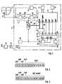
- FIG. 1
- a block diagram of a pacemaker constructed according to the invention, and
- FIG 2 u. 3rd
- the structure of the transmitted data.
In FIG 1 ist ein insgesamt mit (1) bezeichneter Herzschrittmacher dargestellt, der im VVI-Mode arbeitet. Demgemäss steht der Herzschrittmacher (1) über eine in das Ventrikel eines schematisch angedeuteten Herzens (2) eines Lebewesens eingesetzte Elektrode (3) mit dem Herzen (2) in Verbindung.1 shows a cardiac pacemaker, designated as a whole by (1), which operates in VVI mode. Accordingly, the pacemaker (1) is connected to the heart (2) via an electrode (3) inserted into the ventricle of a schematically indicated heart (2) of a living being.
Die Elektrode (3) dient einerseits dazu, ein der elektrischen Aktivität des Herzens (2) entsprechendes Signal zu erfassen und dem Herzschrittmacher (1) zuzuführen. Dort gelangt das Signal zu einer schematisch angedeuteten Detektorschaltung (4), in der das Signal ein EKG-Filter (4a) und einen Verstärker (4b) durchläuft und einer Pegelmesseinheit (4c) zugeführt wird, die bei Auftreten eines Ereignisses mit einer einem natürlichen Herzschlag entsprechenden Mindestamplitude und/oder einer bestimmten, für natürliche Herzschläge typischen Steilheit in dem Ausgangssignal des Verstärkers (4c) ein die Detektion eines natürlichen Herzschlages anzeigendes digitales Signal abgibt. Der Ausgang der Detektorschaltung (4) ist mit einem Eingang (5) einer Steuerlogik (6) verbunden, die anhand der von der Detektorschaltung (4) eingehenden digitalen Signale unter Heranziehung gespeicherter Daten entscheidet, ob und wann eine Stimulation des Herzens (2) erfolgen soll. Ist eine Stimulation des Herzens (2) erforderlich, gibt die Steuerlogik (6) über einen Ausgang (7) zum entsprechenden Zeitpunkt ein Signal an einen Stimulationspuls-Generator (8), der zur Erzeugung eines Stimulationspulses bestimmter Amplitude und Dauer dient.The electrode (3) serves on the one hand to detect a signal corresponding to the electrical activity of the heart (2) and to supply it to the pacemaker (1). There the signal arrives at a schematically indicated detector circuit (4), in which the signal passes through an EKG filter (4a) and an amplifier (4b) and is fed to a level measuring unit (4c) which, when an event occurs with a natural heartbeat corresponding minimum amplitude and / or a certain steepness typical of natural heartbeats in the output signal of the amplifier (4c) emits a digital signal indicating the detection of a natural heartbeat. The output of the detector circuit (4) is connected to an input (5) of a control logic (6) which, based on the digital signals coming in from the detector circuit (4) and using stored data, decides whether and when there is a stimulation of the heart (2) should. If stimulation of the heart (2) is required, the control logic (6) outputs an output (7) at the appropriate time to a signal to a stimulation pulse generator (8) which is used to generate a stimulation pulse of a certain amplitude and duration.
Die Elektrode (3) dient andererseits dazu, dem Herzen (2) Stimulationspulse zuzuführen. Der Ausgang des Stimulationspuls-Generators (8) ist daher mit der Elektrode (3) verbunden.The electrode (3) on the other hand serves to supply stimulation pulses to the heart (2). The output of the stimulation pulse generator (8) is therefore connected to the electrode (3).
Alle für die Funktion der Steuerlogik (6) erforderlichen Zeitsignale werden ausgehend von dem Signal eines Taktgenerators (9), z. B. eines Quarz-Oszillators, gewonnen, der mit einem Takteingang der Steuerlogik (6) verbunden ist. Ausserdem ist eine mit der Steuerlogik (6) verbundene Timerschaltung (21) vorhanden, die zur Messung einer definierten Zeitdauer dient und von der Steuerlogik (6) gestartet wird, sobald ein Stimulationspuls mittels des Stimulationspuls-Generators (8) abgegeben wird. Solange die definierte Zeitdauer läuft, die einer maximal zulässigen Folgefrequenz der Stimulationspulse entspricht, unterbindet die Steuerlogik (6) die Abgabe eines weiteren Stimulationspulses. Auf diese Weise ist vermieden, dass, z.B. im Falle von Störungen des Taktgenerators (9), eine Folgefrequenz der Stimulationspulse auftritt, die physiologisch nicht zulässig ist und den Patienten gefährden würde.All time signals required for the function of the control logic (6) are based on the signal of a clock generator (9), e.g. B. a quartz oscillator, which is connected to a clock input of the control logic (6). There is also a timer circuit (21) connected to the control logic (6), which is used to measure a defined period of time and is started by the control logic (6) as soon as a stimulation pulse is emitted by means of the stimulation pulse generator (8). As long as the defined period of time, which corresponds to a maximum permissible repetition frequency of the stimulation pulses, the control logic (6) prevents the delivery of a further stimulation pulse. In this way it is avoided that e.g. in the event of faults in the clock generator (9), a repetitive frequency of the stimulation pulses occurs that is not physiologically permissible and would endanger the patient.
Die Steuerlogik (6) weist eine Reihe von Ausgängen auf, die in FIG 1 die Bezeichnung REF, ARD, ARP und RAP tragen und jeweils entweder den Zustand logisch "1" oder logisch "0" annehmen können. Im einzelnen besitzt der Ausgang REF den Zustand logisch "1" solange die technische Refraktärzeit läuft. Der Ausgang ARD nimmt den Zustand logisch "1" an, sobald ein natürlicher Herzschlag detektiert wird und behält diesen Zustand bei, solange die absolute technische Refraktärzeit läuft. Der Ausgang ARP nimmt den Zustand logisch "1" an, sobald ein Stimulationspuls abgegeben wird und behält diesen Zustand für die Dauer der absoluten Refraktärzeit bei. Der Ausgang RAP nimmt immer dann, wenn die Timerschaltung (21) gestartet wird, für die Dauer der definierten Zeitdauer den Zustand logisch "1" an, so dass überprüft werden kann, ob die Timerschaltung (21) korrekt arbeitet.The control logic (6) has a series of outputs which in FIG. 1 have the designation REF, ARD, ARP and RAP and can each assume either the logic "1" or logic "0" state. In detail, the output REF has the status logic "1" as long as the technical refractory period is running. The output ARD assumes the state logic "1" as soon as a natural heartbeat is detected and maintains this state as long as the absolute technical refractory period is running. The output ARP assumes the state logic "1" as soon as a stimulation pulse is delivered and maintains this state for the duration of the absolute refractory period. The output RAP takes on the state for the duration of the defined period of time whenever the timer circuit (21) is started logic "1" so that it can be checked whether the timer circuit (21) is working correctly.
Einzelheiten bezüglich der in der Herzschrittmacher-Technologie gängigen Begriffe "technische Refraktärzeit" und "absolute technische Refraktärzeit" können der einschlägigen Literatur entnommen werden (siehe z.B. Druckschrift "DIALOG-Schrittmacher 728" - Gebrauchsanweisung, Oktober 1986, Siemens-Elema AB, Solna, Schweden).Details regarding the terms "technical refractory period" and "absolute technical refractory period" common in pacemaker technology can be found in the relevant literature (see, for example, publication "DIALOG-Pacemaker 728" - Instructions for Use, October 1986, Siemens-Elema AB, Solna, Sweden ).
Es wird somit deutlich, dass an den erwähnten Ausgängen der Steuerlogik (6) Daten zur Verfügung stehen, die dem momentanen logischen Zustand der Steuerlogik (6) entsprechen. Diese Daten können, beispielsweise in geeigneter Form und in korrekter zeitlicher Zuordnung zu einem Elektrodkardiogramm dargestellt, wichtige Aufschlüsse über das Zusammenspiel des Herzschrittmachers (1) mit dem Herzen (2) geben.It is thus clear that data are available at the mentioned outputs of the control logic (6) which correspond to the current logic state of the control logic (6). These data, for example in a suitable form and in the correct chronological assignment to an electrode cardiogram, can provide important information about the interaction of the pacemaker (1) with the heart (2).
Der Herzschrittmacher (1) besitzt daher eine mit den erwähnten Ausgängen der Steuerlogik (6) verbundene Telemetrieschaltung (11), die es gestattet, die dem logischen Zustand der Steuerlogik (6) entsprechenden Daten von dem in den Körper eines Lebewesens implantierten Herzschrittmacher (1) zu einem getrennten Empfänger (12) auf nicht-invasivem Wege zu übertragen.The pacemaker (1) therefore has a telemetry circuit (11) connected to the mentioned outputs of the control logic (6), which allows the data corresponding to the logical state of the control logic (6) to be obtained from the pacemaker (1) implanted in the body of a living being. to be transmitted to a separate receiver (12) in a non-invasive manner.
Die Übertragung der Daten erfolgt auf induktivem Wege, d.h. der Ausgang der Telemetrieschaltung (11) ist mit einer Sendespule (13) verbunden, in deren Nähe eine mit dem Eingang des Empfängers (12) verbundene Empfangsspule (14) derart angeordnet wird, dass diese mit der Sendespule (13) induktiv gekoppelt ist.The data is transmitted inductively, ie the output of the telemetry circuit (11) is connected to a transmitter coil (13), in the vicinity of which a receiver coil (14) connected to the input of the receiver (12) is arranged in such a way that it is connected to the transmitter the transmitter coil (13) is inductively coupled.
Vom Ausgang (15) des Empfängers (12) gelangen die Daten zu einem EKG-Rekorder oder einem anderen Gerät, das zur Auswertung bzw. Darstellung der Daten geeignet ist.From the output (15) of the receiver (12), the data arrive at an EKG recorder or another device that is suitable for evaluating or displaying the data.
Wie aus der FIG 1 ersichtlich ist, ist ein Taktgenerator (16) vorgesehen, der ein Taktsignal erzeugt, das zu einem Takteingang (17) der Telemetrieschaltung (11) gelangt. Bei dem Taktgenerator (16) handelt es sich um einen Oszillator, der ein Signal konstanter Periodendauer abgibt. Geeignete Schaltungen sind dem Fachmann bekannt. Das an dem Takteingang (17) der Telemetrieschaltung (11) anliegende Signal dient dazu, die Telemetrieschaltung (11) zu kontinuierlich, d.h. periodisch aufeinanderfolgenden Zeitpunkten zur Übertragung der dem logischen Zustand der Steuerlogik (6) entsprechenden Daten zu aktivieren.As can be seen from FIG. 1, a clock generator (16) is provided which generates a clock signal which arrives at a clock input (17) of the telemetry circuit (11). The clock generator (16) is an oscillator which emits a signal of constant period. Suitable circuits are known to the person skilled in the art. The signal present at the clock input (17) of the telemetry circuit (11) serves to make the telemetry circuit (11) too continuous, i.e. to activate periodically successive points in time for the transmission of the data corresponding to the logical state of the control logic (6).
Die Telemetrieschaltung (11) enthält ein Schieberegister (18) mit parallelen Eingängen, wobei jeweils einer der genannten Ausgänge der Steuerlogik (6) mit einem Eingang des Schieberegisters (18) verbunden ist, und einem seriellen Ausgang, der über eine Modulatorschaltung (19), z.B. einen FSK-Modulator, mit der Sendespule (13) verbunden ist. Das der Telemetrieschaltung (11) über den Takteingang (17) zugeführte Signal wird mittels einer Taktaufbereitungsschaltung (20) derart aufbereitet, dass es das Schieberegister (18) in einer solchen Weise steuert, dass dieses die unmittelbar vor Beginn einer Datenübertragung an seinen parallelen Eingängen vorhandenen logischen Zustände bzw. Daten speichert, die dann der Modulatorschaltung (19) seriell zugeführt werden. Die Taktaufbereitungsschaltung (20) erzeugt also die zum Betrieb des Schieberegisters (18) erforderlichen Parallel-Eingabe-Taktimpulse, Rückstell-Taktimpulse und Schiebe-Taktimpulse, die entsprechenden Engängen des Schieberegisters (18) zugeführt wird, die mit SET, RES und C1 bezeichnet sind. Das Ausgangssignal der Modulatorschaltung (19) gelangt über die Sendespule (13) und die Empfangsspule (14) zu dem Empfänger (12) und wird dort in geeigneter Weise demoduliert und steht am Ausgang (15) des Empfängers (12) als serieller Datenstrom zur Verfügung.The telemetry circuit (11) contains a shift register (18) with parallel inputs, one of the said outputs of the control logic (6) being connected to an input of the shift register (18) and a serial output which is connected via a modulator circuit (19), For example, an FSK modulator with which the transmitter coil (13) is connected. The signal supplied to the telemetry circuit (11) via the clock input (17) is processed by means of a clock processing circuit (20) in such a way that it controls the shift register (18) in such a way that the shift register (18) is present at its parallel inputs immediately before data transmission begins stores logical states or data, which are then fed to the modulator circuit (19) in series. The clock processing circuit (20) thus generates the parallel input clock pulses, reset clock pulses and shift clock pulses required for operating the shift register (18), the corresponding outputs of the shift register (18), which are supplied with SET, RES and C1 are designated. The output signal of the modulator circuit (19) reaches the receiver (12) via the transmitting coil (13) and the receiving coil (14) and is demodulated there in a suitable manner and is available at the output (15) of the receiver (12) as a serial data stream .
Es wird somit deutlich, dass bei dem erfindungsgemässen Herzschrittmacher (1) die Übertragung der dem logischen Zustand der Steuerlogik (6) entsprechenden Daten unabhängig von dem Auftreten irgendwelcher Ereignisse, z.B. der Detektion eines natürlichen Herzschlages oder der Abgabe eines Stimulationspulses, quasi-kontinuierlich zu periodisch aufeinanderfolgenden Zeitpunkten erfolgt. Dabei werden jeweils die zum Beginn einer Datenübertragung aktuellen Daten übertragen .It is thus clear that in the pacemaker (1) according to the invention, the transmission of the data corresponding to the logical state of the control logic (6) is independent of the occurrence of any events, e.g. the detection of a natural heartbeat or the delivery of a stimulation pulse takes place quasi-continuously at periodically successive times. The data that is current at the start of a data transmission is transmitted in each case.
Bekanntlich besitzt ein Herzschrittmacher eine sich in aufeinanderfolgenden Gerätezyklen vollziehende zyklische Arbeitsweise, wobei die kürzestmögliche Zyklusdauer der Dauer der technischen Refraktärzeit entspricht und die längstmögliche Zyklusdauer durch die Länge eines Zeitintervalles bestimmt ist, dessen Dauer sich aus der Frequenz ergibt, mit der der Herzschrittmacher das Herz im Bedarfsfalle stimuliert. Die Gesamtdauer der technischen Refraktärzeit liegt gewöhnlich in der Grössenordnung von 200 bis 500 ms. Die Taktfrequenz des Taktgenerators (16) ist derart gewählt, dass während eines Gerätezyklus, d.h. während des Ablaufs der jeweils gewählten technischen Refraktärzeit mehrere Datenübertragungen erfolgen. Geht man davon aus, dass im Interesse einer ausreichend zuverlässigen Datenübertragung während eines Gerätezyklus wenigstens 30 Datenübertragungen erfolgen sollen, müssen unter Zugrundelegung einer technischen Refraktärzeit von 240 ms die Datenübertragungen in Abständen von höchstens 8 ms aufeinanderfolgen.As is known, a pacemaker has a cyclical mode of operation which takes place in successive device cycles, the shortest possible cycle duration corresponding to the duration of the technical refractory period and the longest possible cycle duration being determined by the length of a time interval, the duration of which is determined by the frequency with which the pacemaker beats the heart in Stimulates need trap. The total duration of the technical refractory period is usually of the order of 200 to 500 ms. The clock frequency of the clock generator (16) is selected in such a way that several data transmissions take place during a device cycle, ie during the course of the technical refractory time selected in each case. If one assumes that, in the interest of sufficiently reliable data transmission, at least 30 data transmissions should take place during a device cycle, the data transmissions must be based on a technical refractory period of 240 ms at intervals of no more than 8 ms.
Wie aus der FIG 1 ersichtlich ist, gelangt das gefilterte und verstärkte Signal der Elektrode (3) zu einem Digital/Analog-Wandler (24) mit einer Auflösung von beispielsweise 6 bit, der seine Taktsignale von dem Taktgenerator (16) erhält. Das verstärkte und gefilterte Signal entspricht einem intrakardialen Elektrogramm (IEKG) und wird von dem Digital/Analog-Wandler (24) in digitalisierter Form über einen schematisch angedeuteten, 6 bit breiten Datenbus (25) zum einen zu einer elektronischen Schalteinrichtung (22) und zum anderen zu einem mit IEKG bezeichneten Eingang der Steuerlogik (6) geleitet. Wird die Schalteinrichtung (22) über eine Steuerleitung (23) mittels der Steuerlogik (6) in geeigneter Weise betätigt, gelangen die Ausgangsdaten des Analog/Digital-Wandlers (24) zu der Telemetrieschaltung (11), wobei jeweils eine Leitung des Datenbusses (25) mit einem Eingang des Schieberegisters (18) verbunden ist, das insgesamt eine Breite von 10 bit aufweist. Diese überträgt die dem IEKG entsprechenden Daten gemeinsam mit den dem logischen Zustand der Steuerlogik (6) entsprechenden Daten.As can be seen from FIG. 1, the filtered and amplified signal from the electrode (3) reaches a digital / analog converter (24) with a resolution of 6 bits, for example, which receives its clock signals from the clock generator (16). The amplified and filtered signal corresponds to an intracardiac electrogram (IEKG) and is digitized by the digital / analog converter (24) via a schematically indicated, 6 bit wide data bus (25) on the one hand to an electronic switching device (22) and on the other others routed to an input of the control logic (6) labeled IEKG. If the switching device (22) is actuated in a suitable manner via a control line (23) by means of the control logic (6), the output data of the analog / digital converter (24) reach the telemetry circuit (11), one line of the data bus (25 ) is connected to an input of the shift register (18), which has a total width of 10 bits. This transmits the data corresponding to the IEKG together with the data corresponding to the logical state of the control logic (6).
Dies geschieht gemäss FIG 2 in einem einzigen Datenwort mit den 10 bit D0 bis D9, wobei eine zusammenhängende Folge von 6 bit des Datenwortes die dem IEKG entsprechenden digitalen Ausgangssignale des Analog/Digital-Wandlers (24) und eine zusammenhängende Folge von 4 bit Datenwortes die dem logischen Zustand der Steuerlogik (6) entsprechenden Daten enthält.According to FIG. 2, this is done in a single data word with the 10 bits D0 to D9, a continuous sequence of 6 bits of the data word being the digital output signals of the analog / digital converter (24) corresponding to the IEKG and a continuous sequence of 4 bit data words being the contains data corresponding to the logical state of the control logic (6).
Die Steuerlogik (6) errechnet aus den ihr zugeführten digitalen Ausgangssignalen des Analog/Digital-Wandlers (24) und der Mindestamplitude, die das der elektrischen Aktivität des Herzens (2) entsprechende Signal aufweisen muss, um in der Pegelmesseinheit (4c) zur Detektion eines natürlichen Herzschlages zu führen, für jeden detektierten natürlichen Herzschlag das sogenannte Detektionsmarginal. Das Detektionsmarginal gibt an, um welches Mass die Amplitude des der elektrischen Aktivität des Herzens (2) entsprechenden Signals bei der Detektion eines natürlichen Herzschlages die Mindestamplitude übersteigt. Anhand des Detektionsmarginals, das eine wichtige Grösse zur Beurteilung des Betriebszustandes des Herzschrittmachers (1) darstellt, kann also festgestellt werden, ob der eingestellte Wert der Mindesamplitude so gewählt ist, dass alle auftretenden natürlichen Herzschläge mit hoher Wahrscheinlichkeit detektiert werden können. Ist das Detektionsmarginal zu gering, kann eine entsprechende Korrektur des Wertes der Mindestamplitude erfolgen. Dem Detektionsmarginal entsprechende Daten stehen an einem DET MARG bezeichneten Ausgang der Steuerlogik (6) zur Verfügung und sind über einen schematisch angedeuteten 6 bit breiten Datenbus (26) der Schalteinrichtung (22) zugeführt. Betätigt die Steuerlogik (6) die Schalteinrichtung (22) über die Steuerleitung (23) in geeigneter Weise, gelangen anstelle der Ausgangsdaten des Analog/Digital-Wandlers (24) die dem Detektionsmarginal entsprechenden digitalen Daten zu der Telemetrieschaltung (11) bzw. deren Schieberegister (18). Die Telemetrieschaltung (11) überträgt dann die dem Detektionsmarginal entsprechenden Daten gemeinsam mit den dem logischen Zustand der Steuerlogik (6) entsprechenden Daten. Dies geschieht gemäss FIG 3 wieder in einem einzigen Datenwort mit den 10 bit D0 bis D9, wobei eine zusammenhängende Folge von 6 bit des Datenwortes die dem Detektionsmarginal entsprechenden Daten und eine zusammenhängende Folge von 4 bit des Datenwortes die dem logischen Zustand der Steuerlogik (6) entsprechenden Daten enthält.The control logic (6) calculates from the supplied digital output signals of the analog / digital converter (24) and the minimum amplitude that the electrical Activity of the heart (2) must have the corresponding signal in order to lead to the detection of a natural heartbeat in the level measuring unit (4c), the so-called detection margin for each natural heartbeat detected. The detection margin indicates the extent to which the amplitude of the signal corresponding to the electrical activity of the heart (2) exceeds the minimum amplitude when a natural heartbeat is detected. On the basis of the detection margin, which is an important variable for assessing the operating state of the pacemaker (1), it can be determined whether the set value of the minimum amplitude is selected such that all occurring natural heartbeats can be detected with a high degree of probability. If the detection margin is too low, the value of the minimum amplitude can be corrected accordingly. Data corresponding to the detection margin is available at an output of the control logic (6) designated DET MARG and is supplied to the switching device (22) via a schematically indicated 6 bit wide data bus (26). If the control logic (6) actuates the switching device (22) in a suitable manner via the control line (23), instead of the output data of the analog / digital converter (24), the digital data corresponding to the detection margin arrive at the telemetry circuit (11) or its shift register (18). The telemetry circuit (11) then transmits the data corresponding to the detection margin together with the data corresponding to the logical state of the control logic (6). According to FIG. 3, this takes place again in a single data word with the 10 bits D0 to D9, a continuous sequence of 6 bits of the data word representing the data corresponding to the detection margin and a continuous sequence of 4 bits of the data word reflecting the logical state of the control logic (6). contains corresponding data.
Es besteht auch die Möglichkeit, dass die Steuerlogik (6) die Schalteinrichtung (22) in einer solchen Weise betätigt, dass diese als Multiplexer wirkt und die Telemetrieschaltung (11) abwechselnd ein Datenwort gemäss FIG 2 und ein Datenwort gemäss FIG 3 usw. überträgt.There is also the possibility that the control logic (6) actuates the switching device (22) in such a way that it acts as a multiplexer and the telemetry circuit (11) alternately transmits a data word according to FIG. 2 and a data word according to FIG.
Zusätzlich zu den Daten werden unter Umständen in nicht dargestellter und an sich bekannter Weise Synchronisierungsimpulse und Stop-bits zu dem Empfänger (12) übertragen.In addition to the data, synchronization pulses and stop bits may be transmitted to the receiver (12) in a manner not shown and known per se.
Im Falle des beschriebenen Ausführungsbeispieles ist ein besonderer Taktgenerator (16) vorgesehen, der die Telemetrieschaltung (11) zur Datenübertragung aktiviert. Die Funktion des Taktgenerators (16) kann aber auch von dem der Steuerlogik (6) zugeordneten Taktgenerator (9) wahrgenommen werden, wenn das Signal des Taktgenerators (9) in geeigneter Weise aufbereitet und dem Takteingang (18) der Telemetrieschaltung (11) zugeführt wird. In Fällen, in denen ein bidirektionaler Datenverkehr zwischen dem Herzschrittmacher (1) und einem externen Gerät stattfindet, dies ist z. B. im Falle von programmierbaren Herzschrittmachern der Fall, besteht auch die Möglichkeit, dass sich der Taktgenerator in dem externen Gerät befindet und die die Telemetrieschaltung (11) des Herzschrittmachers (1) zur Übertragung von Daten aktivierenden Signale telemetrisch zu der Telemetrieschaltung (11) übertragen werden. In diesem Falle können der Steuerlogik (6) zur Betätigung der Schalteinrichtung (22) dienende Signale telemetrisch zugeführt werden.In the case of the exemplary embodiment described, a special clock generator (16) is provided which activates the telemetry circuit (11) for data transmission. The function of the clock generator (16) can, however, also be performed by the clock generator (9) assigned to the control logic (6) if the signal of the clock generator (9) is processed in a suitable manner and supplied to the clock input (18) of the telemetry circuit (11) . In cases where there is bidirectional data traffic between the pacemaker (1) and an external device, this is e.g. B. in the case of programmable pacemakers, there is also the possibility that the clock generator is in the external device and the telemetry circuit (11) of the pacemaker (1) for transmitting data activating signals telemetrically to the telemetry circuit (11) become. In this case, the control logic (6) for actuating the switching device (22) can be fed telemetrically.
Die im Falle des beschriebenen Ausführungsbeispiels zur telemetrischen Übertragung bestimmten Daten sind nur beispielhaft zu verstehen. Es können auch weitere oder andere Daten übertragen werden.The data intended for telemetric transmission in the case of the exemplary embodiment described are only to be understood as examples. Additional or different data can also be transmitted.
Die Erfindung ist vorstehend zwar nur am Beispiel eines implantierbaren Herzschrittmachers beschrieben. Sie kann jedoch auch bei anderen implantierbaren medizinischen Geräten Anwendung finden.The invention has only been described above using the example of an implantable pacemaker. However, it can also be used with other implantable medical devices.
Claims (7)
- Medical apparatus (1) which can be implanted into the body of a living organism,
having means (3,4,4a,4b,4c) for the detection of physiological events and/or having means (3,8) for the stimulation of physiological processes,
having a control logic (6) which is provided with outputs and to which the detecting means (3,4,4a,4b,4c) and/or the stimulating means (3,8) are connected,
and having means (11,13) for the telemetric transmission of data concerning the logic state of the control logic (6) to an external receiver (12), the means (11,13) for the transmission of data being connected to the control logic (6), characterized in that
the means (11,13) for the transmission of data include means (17,18,20) for the acquisition of the data at the outputs of the control logic (6), these data corresponding to the instantaneous logic state of the control logic (6), and the means (17,18,20) for the acquisition of the data being activated substantially simultaneously with the transmission means (11,13),
the transmission means (11,13) additionally exhibit a clock generator (16), which repetitively activates the transmission means (11,13) and the means (17,18,20) for the acquisition of the data at the instants which are specified by the clock generator (16) and which are periodically successive, the frequency of the clock generator (16) being higher than the change-over frequency of the logic state of the control logic (6). - Apparatus according to Claim 1, which apparatus possesses a cyclic mode of operation which is implemented in successive apparatus cycles, characterized in that the clock generator (16) repeatedly activates the means (11,13) for the transmission of data during an apparatus cycle.
- Apparatus according to one of Claims 1 to 2, characterized in that the means (11,13) for the transmission of data transmit the data serially.
- Apparatus according to one of Claims 1 to 3, characterized in that the apparatus (1) is designed as cardiac pacemaker, in which the means (3,4,4a,4b,4c) for the detection of physiological events monitor the electrical activity of the heart (2) and the means (3,8) for the stimulation of physiological processes stimulate the heart (2).
- Apparatus according to one of Claims 1 to 4, characterized in that the means (3,4,4a,4b,4c) for the detection of physiological events form an electrical signal which corresponds to the associated physiological function and which is fed to an analog/digital converter (24), the digital output signal of which is fed to the means (11,13) for the transmission of data, which transmit said signal to the receiver (12).
- Apparatus according to one of Claims 1 to 5, characterized in that it is possible to feed to the means (11,13) for the transmission of data, besides data concerning the logic state of the control logic (6), further data concerning the operational state of the apparatus (1), which the means (11,13) for the transmission of data transmit to the receiver (12).
- Apparatus according to Claim 5 or 6, characterized in that the means (11,13) for the transmission of data transmit both the data corresponding to the logic state of the control logic (6) and also the digital output signals of the analog/digital converter (24) or the data concerning the operational state of the apparatus (1) in the form of a single data word (D0 to D9), in each instance a cohesive bit sequence (D0 to D3 or respectively D4 to D9) of the data word (D0 to D9) including the data corresponding to the logic state of the control logic (6) and the digital output signals of the analog/digital converter (24) or the data concerning the operational state of the apparatus (1).
Priority Applications (5)
| Application Number | Priority Date | Filing Date | Title |
|---|---|---|---|
| EP89106275AEP0392032B1 (en) | 1989-04-10 | 1989-04-10 | Medical implantable apparatus with telematic data transmission means |
| DE58908945TDE58908945D1 (en) | 1989-04-10 | 1989-04-10 | Implantable medical device with means for the telemetric transmission of data. |
| US07/505,509US5016634A (en) | 1989-04-10 | 1990-04-06 | Implantable medical device with means for telemetric transmission of data |
| AU53070/90AAU627017B2 (en) | 1989-04-10 | 1990-04-09 | An implantable medical instrument with means for telemetric data transmission |
| JP2094903AJPH02291874A (en) | 1989-04-10 | 1990-04-09 | Implantable medical device |
Applications Claiming Priority (1)
| Application Number | Priority Date | Filing Date | Title |
|---|---|---|---|
| EP89106275AEP0392032B1 (en) | 1989-04-10 | 1989-04-10 | Medical implantable apparatus with telematic data transmission means |
Publications (2)
| Publication Number | Publication Date |
|---|---|
| EP0392032A1 EP0392032A1 (en) | 1990-10-17 |
| EP0392032B1true EP0392032B1 (en) | 1995-01-25 |
Family
ID=8201197
Family Applications (1)
| Application Number | Title | Priority Date | Filing Date |
|---|---|---|---|
| EP89106275ARevokedEP0392032B1 (en) | 1989-04-10 | 1989-04-10 | Medical implantable apparatus with telematic data transmission means |
Country Status (5)
| Country | Link |
|---|---|
| US (1) | US5016634A (en) |
| EP (1) | EP0392032B1 (en) |
| JP (1) | JPH02291874A (en) |
| AU (1) | AU627017B2 (en) |
| DE (1) | DE58908945D1 (en) |
Families Citing this family (66)
| Publication number | Priority date | Publication date | Assignee | Title |
|---|---|---|---|---|
| AU645848B2 (en)* | 1991-01-15 | 1994-01-27 | Pacesetter Ab | A system and method for post-processing intracardiac signals |
| US5431691A (en)* | 1992-03-02 | 1995-07-11 | Siemens Pacesetter, Inc. | Method and system for recording and displaying a sequential series of pacing events |
| BR9306964A (en)* | 1992-08-31 | 1999-01-12 | Lipomatrix Inc | Medical information storage device for humans |
| US5383909A (en)* | 1993-01-29 | 1995-01-24 | Medtronic, Inc. | Diagnostic telemetry system for an apparatus for detection and treatment of tachycardia and fibrillation |
| US5423334A (en)* | 1993-02-01 | 1995-06-13 | C. R. Bard, Inc. | Implantable medical device characterization system |
| US5372607A (en)* | 1993-06-23 | 1994-12-13 | Medtronic, Inc. | Method and apparatus for monitoring pacemaker intervals |
| US5507786A (en)* | 1994-04-14 | 1996-04-16 | Pacesetter, Inc. | System and method for measuring and storing parametric data pertaining to operating characteristics of an implantable medical device |
| US5666958A (en)* | 1995-04-06 | 1997-09-16 | Rothenberg; Peter M. | Interface module for electrically connecting medical equipment |
| US6895281B1 (en) | 2000-03-31 | 2005-05-17 | Cardiac Pacemakers, Inc. | Inductive coil apparatus for bio-medical telemetry |
| US7342508B2 (en)* | 2003-12-26 | 2008-03-11 | Medtronic Minimed, Inc. | Telemetry system and method with variable parameters |
| US8836513B2 (en) | 2006-04-28 | 2014-09-16 | Proteus Digital Health, Inc. | Communication system incorporated in an ingestible product |
| US9198608B2 (en) | 2005-04-28 | 2015-12-01 | Proteus Digital Health, Inc. | Communication system incorporated in a container |
| US8802183B2 (en) | 2005-04-28 | 2014-08-12 | Proteus Digital Health, Inc. | Communication system with enhanced partial power source and method of manufacturing same |
| US8730031B2 (en) | 2005-04-28 | 2014-05-20 | Proteus Digital Health, Inc. | Communication system using an implantable device |
| US8912908B2 (en) | 2005-04-28 | 2014-12-16 | Proteus Digital Health, Inc. | Communication system with remote activation |
| EP3827747A1 (en) | 2005-04-28 | 2021-06-02 | Otsuka Pharmaceutical Co., Ltd. | Pharma-informatics system |
| US8547248B2 (en) | 2005-09-01 | 2013-10-01 | Proteus Digital Health, Inc. | Implantable zero-wire communications system |
| JP2009544338A (en) | 2006-05-02 | 2009-12-17 | プロテウス バイオメディカル インコーポレイテッド | Treatment regimen customized to the patient |
| EP2087589B1 (en) | 2006-10-17 | 2011-11-23 | Proteus Biomedical, Inc. | Low voltage oscillator for medical devices |
| SG175681A1 (en) | 2006-10-25 | 2011-11-28 | Proteus Biomedical Inc | Controlled activation ingestible identifier |
| US8718193B2 (en) | 2006-11-20 | 2014-05-06 | Proteus Digital Health, Inc. | Active signal processing personal health signal receivers |
| CN101686800A (en) | 2007-02-01 | 2010-03-31 | 普罗秋斯生物医学公司 | Ingestible Event Marker System |
| US8956288B2 (en) | 2007-02-14 | 2015-02-17 | Proteus Digital Health, Inc. | In-body power source having high surface area electrode |
| EP2063771A1 (en) | 2007-03-09 | 2009-06-03 | Proteus Biomedical, Inc. | In-body device having a deployable antenna |
| EP2124725A1 (en) | 2007-03-09 | 2009-12-02 | Proteus Biomedical, Inc. | In-body device having a multi-directional transmitter |
| US8115618B2 (en) | 2007-05-24 | 2012-02-14 | Proteus Biomedical, Inc. | RFID antenna for in-body device |
| DK2192946T3 (en) | 2007-09-25 | 2022-11-21 | Otsuka Pharma Co Ltd | In-body device with virtual dipole signal amplification |
| CN104376659B (en) | 2008-03-05 | 2019-10-25 | 普罗透斯数字保健公司 | The ingestible event flag of multi-modal communications and system, and the method using it |
| AU2009268827B2 (en) | 2008-07-08 | 2013-10-24 | Proteus Digital Health, Inc. | Ingestible event marker data framework |
| MY154217A (en) | 2008-08-13 | 2015-05-15 | Proteus Digital Health Inc | Ingestible circuitry |
| US8036748B2 (en) | 2008-11-13 | 2011-10-11 | Proteus Biomedical, Inc. | Ingestible therapy activator system and method |
| EP2358270A4 (en) | 2008-12-11 | 2014-08-13 | Proteus Digital Health Inc | Evaluation of gastrointestinal function using portable electroviscerography systems and methods of using the same |
| US9659423B2 (en) | 2008-12-15 | 2017-05-23 | Proteus Digital Health, Inc. | Personal authentication apparatus system and method |
| TWI503101B (en) | 2008-12-15 | 2015-10-11 | Proteus Digital Health Inc | Body-associated receiver and method |
| US9439566B2 (en) | 2008-12-15 | 2016-09-13 | Proteus Digital Health, Inc. | Re-wearable wireless device |
| SG172847A1 (en) | 2009-01-06 | 2011-08-29 | Proteus Biomedical Inc | Pharmaceutical dosages delivery system |
| KR20110103446A (en) | 2009-01-06 | 2011-09-20 | 프로테우스 바이오메디컬, 인코포레이티드 | Intake-Related Biofeedback and Individualized Medical Treatment Methods and Systems |
| WO2010111403A2 (en) | 2009-03-25 | 2010-09-30 | Proteus Biomedical, Inc. | Probablistic pharmacokinetic and pharmacodynamic modeling |
| EP3906845A1 (en) | 2009-04-28 | 2021-11-10 | Otsuka Pharmaceutical Co., Ltd. | Highly reliable ingestible event markers |
| EP2432458A4 (en) | 2009-05-12 | 2014-02-12 | Proteus Digital Health Inc | Ingestible event markers comprising an ingestible component |
| US8558563B2 (en) | 2009-08-21 | 2013-10-15 | Proteus Digital Health, Inc. | Apparatus and method for measuring biochemical parameters |
| TWI517050B (en) | 2009-11-04 | 2016-01-11 | 普羅托斯數位健康公司 | System for supply chain management |
| UA109424C2 (en) | 2009-12-02 | 2015-08-25 | PHARMACEUTICAL PRODUCT, PHARMACEUTICAL TABLE WITH ELECTRONIC MARKER AND METHOD OF MANUFACTURING PHARMACEUTICAL TABLETS | |
| BR112012019212A2 (en) | 2010-02-01 | 2017-06-13 | Proteus Digital Health Inc | data collection system |
| WO2011127252A2 (en) | 2010-04-07 | 2011-10-13 | Proteus Biomedical, Inc. | Miniature ingestible device |
| TWI557672B (en) | 2010-05-19 | 2016-11-11 | 波提亞斯數位康健公司 | Computer system and computer-implemented method to track medication from manufacturer to a patient, apparatus and method for confirming delivery of medication to a patient, patient interface device |
| JP2014504902A (en) | 2010-11-22 | 2014-02-27 | プロテウス デジタル ヘルス, インコーポレイテッド | Ingestible device with medicinal product |
| WO2012125425A2 (en) | 2011-03-11 | 2012-09-20 | Proteus Biomedical, Inc. | Wearable personal body associated device with various physical configurations |
| US9756874B2 (en) | 2011-07-11 | 2017-09-12 | Proteus Digital Health, Inc. | Masticable ingestible product and communication system therefor |
| WO2015112603A1 (en) | 2014-01-21 | 2015-07-30 | Proteus Digital Health, Inc. | Masticable ingestible product and communication system therefor |
| PH12014500174A1 (en) | 2011-07-21 | 2024-02-12 | Proteus Digital Health Inc | Mobile communication device, system, and method |
| US9235683B2 (en) | 2011-11-09 | 2016-01-12 | Proteus Digital Health, Inc. | Apparatus, system, and method for managing adherence to a regimen |
| EP2874886B1 (en) | 2012-07-23 | 2023-12-20 | Otsuka Pharmaceutical Co., Ltd. | Techniques for manufacturing ingestible event markers comprising an ingestible component |
| AU2013331417B2 (en) | 2012-10-18 | 2016-06-02 | Proteus Digital Health, Inc. | Apparatus, system, and method to adaptively optimize power dissipation and broadcast power in a power source for a communication device |
| CA3126430C (en) | 2012-11-12 | 2023-03-07 | Empi, Inc. | Systems and methods for wireless pairing and communication for electro-stimulation |
| US11149123B2 (en) | 2013-01-29 | 2021-10-19 | Otsuka Pharmaceutical Co., Ltd. | Highly-swellable polymeric films and compositions comprising the same |
| JP6498177B2 (en) | 2013-03-15 | 2019-04-10 | プロテウス デジタル ヘルス, インコーポレイテッド | Identity authentication system and method |
| WO2014144738A1 (en) | 2013-03-15 | 2014-09-18 | Proteus Digital Health, Inc. | Metal detector apparatus, system, and method |
| EP3005281A4 (en) | 2013-06-04 | 2017-06-28 | Proteus Digital Health, Inc. | System, apparatus and methods for data collection and assessing outcomes |
| US9796576B2 (en) | 2013-08-30 | 2017-10-24 | Proteus Digital Health, Inc. | Container with electronically controlled interlock |
| CA2965941C (en) | 2013-09-20 | 2020-01-28 | Proteus Digital Health, Inc. | Methods, devices and systems for receiving and decoding a signal in the presence of noise using slices and warping |
| WO2015044722A1 (en) | 2013-09-24 | 2015-04-02 | Proteus Digital Health, Inc. | Method and apparatus for use with received electromagnetic signal at a frequency not known exactly in advance |
| US10084880B2 (en) | 2013-11-04 | 2018-09-25 | Proteus Digital Health, Inc. | Social media networking based on physiologic information |
| US11051543B2 (en) | 2015-07-21 | 2021-07-06 | Otsuka Pharmaceutical Co. Ltd. | Alginate on adhesive bilayer laminate film |
| KR20210018961A (en) | 2016-07-22 | 2021-02-18 | 프로테우스 디지털 헬스, 인코포레이티드 | Electromagnetic sensing and detection of ingestible event markers |
| CN109963499B (en) | 2016-10-26 | 2022-02-25 | 大冢制药株式会社 | Method for manufacturing capsules with ingestible event markers |
Family Cites Families (8)
| Publication number | Priority date | Publication date | Assignee | Title |
|---|---|---|---|---|
| US4556063A (en)* | 1980-10-07 | 1985-12-03 | Medtronic, Inc. | Telemetry system for a medical device |
| US4374382A (en)* | 1981-01-16 | 1983-02-15 | Medtronic, Inc. | Marker channel telemetry system for a medical device |
| US4571589A (en)* | 1982-11-22 | 1986-02-18 | Cordis Corporation | Biomedical implant with high speed, low power two-way telemetry |
| EP0120250B1 (en)* | 1983-02-11 | 1989-06-21 | Vitatron Medical B.V. | Biomedical system with improved marker channel means and method |
| AU2883784A (en)* | 1983-06-15 | 1984-12-20 | Medtronic, Inc. | Organ capture detection for electrical stimulators |
| US4681111A (en)* | 1985-04-05 | 1987-07-21 | Siemens-Pacesetter, Inc. | Analog and digital telemetry system for an implantable device |
| US4705043A (en)* | 1985-07-05 | 1987-11-10 | Mieczslaw Mirowski | Electrophysiology study system using implantable cardioverter/pacer |
| EP0225839B1 (en)* | 1985-09-17 | 1993-12-01 | BIOTRONIK Mess- und Therapiegeräte GmbH & Co Ingenieurbüro Berlin | Heart pacemaker |
- 1989
- 1989-04-10EPEP89106275Apatent/EP0392032B1/ennot_activeRevoked
- 1989-04-10DEDE58908945Tpatent/DE58908945D1/ennot_activeRevoked
- 1990
- 1990-04-06USUS07/505,509patent/US5016634A/ennot_activeExpired - Lifetime
- 1990-04-09JPJP2094903Apatent/JPH02291874A/enactivePending
- 1990-04-09AUAU53070/90Apatent/AU627017B2/ennot_activeCeased
Non-Patent Citations (1)
| Title |
|---|
| A. Bruce Carlson, "Communication systems", McGraw Hill Book Company, 1986, Seiten 470 und 471* |
Also Published As
| Publication number | Publication date |
|---|---|
| AU5307090A (en) | 1990-10-11 |
| US5016634A (en) | 1991-05-21 |
| EP0392032A1 (en) | 1990-10-17 |
| AU627017B2 (en) | 1992-08-13 |
| JPH02291874A (en) | 1990-12-03 |
| DE58908945D1 (en) | 1995-03-09 |
Similar Documents
| Publication | Publication Date | Title |
|---|---|---|
| EP0392032B1 (en) | Medical implantable apparatus with telematic data transmission means | |
| DE2803366C2 (en) | ||
| DE3243094A1 (en) | IMPLANTABLE IRRITATING DEVICE | |
| DE69832639T2 (en) | Implantable pacemaker system | |
| DE3117075C2 (en) | Atrial synchronous pacemaker | |
| EP0422271A1 (en) | Medical apparatus implantable in the body of a livingbeing with means for stimulating tissue contraction and method of stimulation | |
| DE2929498A1 (en) | IMPLANTABLE ELECTRONIC DEVICE | |
| EP0464252B1 (en) | Device for tissue stimulation | |
| EP0399059B2 (en) | Implantable medical device with adjustable sensitivity to detect an event relating to a physiological function, and process for using same | |
| EP0793980A2 (en) | Signal storage device in an implantable medical apparatus | |
| DE2322836A1 (en) | MONITORING DEVICE | |
| DE3587786T2 (en) | MEASURING THE HEART BEAT INTERVAL OF A STIMULATED HEART, ADAPTING HEART PACEMAKER AND MODE. | |
| EP0416138A1 (en) | Medical apparatus cooperating with a living being for stimulating and/or monitoring a physiological function | |
| EP0108360A1 (en) | Heart pacemaker for arresting a tachycardia | |
| EP0783902A2 (en) | Extracorporal control device for an implantable medical device | |
| DE2944542A1 (en) | DEVICE FOR PROGRAMMING IMPLANTED ELECTRONIC DEVICES, IN PARTICULAR PACER GENERATORS | |
| DE69529326T2 (en) | Dual-chamber pacemaker system with improved switching between synchronous and asynchronous modes | |
| EP0490985B1 (en) | Medical appliance for stimulating tissue contractions | |
| DE69629876T2 (en) | Device for stimulating the heart with variable pulse energy | |
| EP0381799B2 (en) | Implantable cardiac pacer with a synchrous rate of stimulation of the cardiac muscle limited to a maximal value | |
| DE69632673T2 (en) | Pacemaker with evoked response detection | |
| DE4416779B4 (en) | Device for avoiding the temporal coincidence of stimulated and spontaneous cardiac reactions | |
| DE3303104A1 (en) | Device for monitoring cardiac action | |
| DE602006000649T2 (en) | Active implantable medical device, in particular pacemaker, resynchronizer, defibrillator and / or cardioverter, with tools for diagnosing the condition of a patient | |
| EP0077800A1 (en) | Pacemaker. |
Legal Events
| Date | Code | Title | Description |
|---|---|---|---|
| PUAI | Public reference made under article 153(3) epc to a published international application that has entered the european phase | Free format text:ORIGINAL CODE: 0009012 | |
| AK | Designated contracting states | Kind code of ref document:A1 Designated state(s):DE FR GB IT NL SE | |
| 17P | Request for examination filed | Effective date:19901220 | |
| 17Q | First examination report despatched | Effective date:19930713 | |
| GRAA | (expected) grant | Free format text:ORIGINAL CODE: 0009210 | |
| AK | Designated contracting states | Kind code of ref document:B1 Designated state(s):DE FR GB IT NL SE | |
| RAP1 | Party data changed (applicant data changed or rights of an application transferred) | Owner name:PACESETTER AB | |
| REF | Corresponds to: | Ref document number:58908945 Country of ref document:DE Date of ref document:19950309 | |
| ITF | It: translation for a ep patent filed | ||
| PG25 | Lapsed in a contracting state [announced via postgrant information from national office to epo] | Ref country code:SE Effective date:19950425 | |
| GBT | Gb: translation of ep patent filed (gb section 77(6)(a)/1977) | Effective date:19950328 | |
| ET | Fr: translation filed | ||
| PLBI | Opposition filed | Free format text:ORIGINAL CODE: 0009260 | |
| 26 | Opposition filed | Opponent name:BIOTRONIK MESS- UND THERAPIEGERAETE GMBH & CO INGE Effective date:19951025 | |
| PLBF | Reply of patent proprietor to notice(s) of opposition | Free format text:ORIGINAL CODE: EPIDOS OBSO | |
| NLR1 | Nl: opposition has been filed with the epo | Opponent name:BIOTRONIK MESS- UND THERAPIEGERAETE GMBH & CO INGE | |
| PLBF | Reply of patent proprietor to notice(s) of opposition | Free format text:ORIGINAL CODE: EPIDOS OBSO | |
| PLAW | Interlocutory decision in opposition | Free format text:ORIGINAL CODE: EPIDOS IDOP | |
| APAC | Appeal dossier modified | Free format text:ORIGINAL CODE: EPIDOS NOAPO | |
| APAE | Appeal reference modified | Free format text:ORIGINAL CODE: EPIDOS REFNO | |
| APAC | Appeal dossier modified | Free format text:ORIGINAL CODE: EPIDOS NOAPO | |
| APCC | Communication from the board of appeal sent | Free format text:ORIGINAL CODE: EPIDOS OBAPO | |
| PGFP | Annual fee paid to national office [announced via postgrant information from national office to epo] | Ref country code:GB Payment date:19980320 Year of fee payment:10 | |
| RAP2 | Party data changed (patent owner data changed or rights of a patent transferred) | Owner name:PACESETTER AB | |
| APCC | Communication from the board of appeal sent | Free format text:ORIGINAL CODE: EPIDOS OBAPO | |
| NLT2 | Nl: modifications (of names), taken from the european patent patent bulletin | Owner name:PACESETTER AB | |
| PG25 | Lapsed in a contracting state [announced via postgrant information from national office to epo] | Ref country code:GB Free format text:LAPSE BECAUSE OF NON-PAYMENT OF DUE FEES Effective date:19990410 | |
| PGFP | Annual fee paid to national office [announced via postgrant information from national office to epo] | Ref country code:NL Payment date:19990429 Year of fee payment:11 | |
| GBPC | Gb: european patent ceased through non-payment of renewal fee | Effective date:19990410 | |
| PG25 | Lapsed in a contracting state [announced via postgrant information from national office to epo] | Ref country code:NL Free format text:LAPSE BECAUSE OF NON-PAYMENT OF DUE FEES Effective date:20001101 | |
| NLV4 | Nl: lapsed or anulled due to non-payment of the annual fee | Effective date:20001101 | |
| RAP2 | Party data changed (patent owner data changed or rights of a patent transferred) | Owner name:ST. JUDE MEDICAL AB | |
| PLAB | Opposition data, opponent's data or that of the opponent's representative modified | Free format text:ORIGINAL CODE: 0009299OPPO | |
| PLBQ | Unpublished change to opponent data | Free format text:ORIGINAL CODE: EPIDOS OPPO | |
| R26 | Opposition filed (corrected) | Opponent name:BIOTRONIK MESS- UND THERAPIEGERAETE GMBH & CO INGE Effective date:19951025 | |
| PGFP | Annual fee paid to national office [announced via postgrant information from national office to epo] | Ref country code:DE Payment date:20030429 Year of fee payment:15 | |
| PLAB | Opposition data, opponent's data or that of the opponent's representative modified | Free format text:ORIGINAL CODE: 0009299OPPO | |
| R26 | Opposition filed (corrected) | Opponent name:BIOTRONIK GMBH & CO. KG Effective date:19951025 | |
| PGFP | Annual fee paid to national office [announced via postgrant information from national office to epo] | Ref country code:FR Payment date:20040330 Year of fee payment:16 | |
| APBU | Appeal procedure closed | Free format text:ORIGINAL CODE: EPIDOSNNOA9O | |
| RDAF | Communication despatched that patent is revoked | Free format text:ORIGINAL CODE: EPIDOSNREV1 | |
| RDAG | Patent revoked | Free format text:ORIGINAL CODE: 0009271 | |
| STAA | Information on the status of an ep patent application or granted ep patent | Free format text:STATUS: PATENT REVOKED | |
| 27W | Patent revoked | Effective date:20040213 | |
| APAH | Appeal reference modified | Free format text:ORIGINAL CODE: EPIDOSCREFNO | |
| PGFP | Annual fee paid to national office [announced via postgrant information from national office to epo] | Ref country code:IT Payment date:20060430 Year of fee payment:18 |