EP0391149B2 - Portable bridge and system for placing the bridge - Google Patents
Portable bridge and system for placing the bridgeDownload PDFInfo
- Publication number
- EP0391149B2 EP0391149B2EP90105406AEP90105406AEP0391149B2EP 0391149 B2EP0391149 B2EP 0391149B2EP 90105406 AEP90105406 AEP 90105406AEP 90105406 AEP90105406 AEP 90105406AEP 0391149 B2EP0391149 B2EP 0391149B2
- Authority
- EP
- European Patent Office
- Prior art keywords
- bridge
- section
- carriageway
- sections
- roadway
- Prior art date
- Legal status (The legal status is an assumption and is not a legal conclusion. Google has not performed a legal analysis and makes no representation as to the accuracy of the status listed.)
- Expired - Lifetime
Links
- 238000010276constructionMethods0.000description5
- 230000008878couplingEffects0.000description4
- 238000010168coupling processMethods0.000description4
- 238000005859coupling reactionMethods0.000description4
- 230000015572biosynthetic processEffects0.000description2
- 238000009434installationMethods0.000description2
- 239000000969carrierSubstances0.000description1
- 230000007123defenseEffects0.000description1
- 238000011161developmentMethods0.000description1
- 230000018109developmental processEffects0.000description1
- 238000000034methodMethods0.000description1
- 230000002787reinforcementEffects0.000description1
Images


Classifications
- E—FIXED CONSTRUCTIONS
- E01—CONSTRUCTION OF ROADS, RAILWAYS, OR BRIDGES
- E01D—CONSTRUCTION OF BRIDGES, ELEVATED ROADWAYS OR VIADUCTS; ASSEMBLY OF BRIDGES
- E01D15/00—Movable or portable bridges; Floating bridges
- E01D15/12—Portable or sectional bridges
- E01D15/127—Portable or sectional bridges combined with ground-supported vehicles for the transport, handling or placing of such bridges or of sections thereof
Definitions
- the inventionrelates to a layable bridge, which has one or more bridge sections provided with a roadway on the top, and a laying system.
- Such bridgeswhich are mostly used as pioneering bridges, are usually pushed and deposited over an obstacle (river, ditch) with the aid of a vehicle provided with a laying device, and in most cases also transported on this vehicle at the same time.
- the bridgescan - in relation to their longitudinal direction - be made in one piece, i.e. consist of only a single bridge section or element, or be composed of several individual bridge sections. All bridges have in common that a ramp is formed at both ends. Particularly with the shorter bridges of this type, particular difficulties arise from the fact that only a certain bridge length can be loaded on a vehicle, which is then available at the place of use, it often being impossible to predict which bridge length is currently required.
- a layable bridgewhich consists of bridge sections provided with a carriageway on the top.
- Each bridge sectionhas a lower flange, in the middle of which a roadway arrangement is articulated, which - seen from the side - consists of a roadway and two length-adjustable support struts, the support struts on the one hand at one end of the roadway and on the other hand together in are articulated in the middle of the lower flange.
- the shape of the triangular construction formed by the carriageway and the support strutscan be changed, as a result of which the average height of the carriageway provided with a support can be adjusted relative to the lower flange.
- the triangular constructioncan be swiveled around the middle of the lower chord, which also determines the inclination of the road. Due to the articulation of the triangular construction in only one joint axis, each individual bridge section is not stable in itself. A bridge must therefore consist of at least two coupled bridge sections.
- a bridgeconsisting of a bridge section or composed of several bridge sections, in which the or each bridge section over its entire length has a fixed lower flange and is provided with a roadway section which occupies half the length of the bridge section and is pivotably mounted about a horizontal axis running perpendicular to the longitudinal direction of the bridge.
- the bridge sectionscan individually span a narrow obstacle with the movable roadway folded down.
- two bridge sections that are coupled togethercan also span a wider obstacle, the movable roadway sections being folded up and supported at the coupled ends of the bridge sections.
- When laying the bridge sectionsthey slide on sliding pads of a laying device, which requires a considerable width of the laying device. Only to apply a counter torque in the case of an overhanging bridge section is provided at its rear end with rollers which engage in guide grooves in the laying device.
- the inventionhas for its object to design a relocatable bridge of the type mentioned so that in particular the bridge sections carried on a vehicle enable the construction of bridges of different lengths.
- the bridge sectionhas at least one fixed lower flange over its entire length and is provided with at least one joint having a horizontal and perpendicular axis to the longitudinal direction of the bridge, which is fixed in relation to side walls, supports or the like is arranged on the lower chord and around which a roadway section located in the end region of the bridge section, which makes up part of the length of the bridge section, can be pivoted, and that running rails are arranged on the lower chord.
- the roadway and the roadway sectionwhich only makes up part of the length of the bridge section, can be designed in one piece or - as is usually provided for pioneer bridges - as two parallel track lines. Due to the running rails arranged on the lower flange, the bridge section can be moved on a laying device. Instead of attaching rails to the lower flange, this can also be designed in the form of rails.
- the inventionenables a large number of different configurations of the bridge sections and, associated therewith, the formation of a greater number of different bridge lengths using a few bridge sections.
- a particularly advantageous design for the new bridge sectionsresults from the fact that the joint is arranged in the region of the top of the carriageway and that the carriageway section is provided with at least one carrier.
- the carriercan simultaneously form the side walls of the carriageway section, so that there is a stable U-shape for the cross section of the carriageway section.
- the articulated section of the carriagewayshould preferably be lockable at least in its end positions in order to stiffen the bridge in the event of a load. Shear stresses that occur can be distributed in a simple manner in the longitudinal direction of the bridge in that the determination in the lower position of the roadway section is formed by the engagement of a toothing.
- Linear motorspreferably hydraulic cylinders, are particularly suitable as adjusting devices, which are also particularly suitable for absorbing larger loads.
- An embodimentis particularly suitable for the formation of short bridges, in which the bridge section has two ramp-shaped areas, at least one of which is designed as a pivotable roadway section is trained. This has particular advantages if two such bridge sections can be loaded one above the other on a laying vehicle and can be coupled to one another with the roadway sections pivoted upwards. The loaded bridge sections can thus form two short bridges or be combined to form a bridge twice as long.
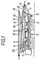
- the vehicle 2provided with a laying device 1 at its rear end carries two respectively identical bridge elements or sections 3 and 4, which lie one above the other on a frame 5 which can be pushed out towards the rear end of the vehicle 2.
- the frame 5also carries the laying device 1 and is further provided at its free end with floor support elements 6 which can be extended downwards.
- a lever 7 articulated at the front end of the frame 5also serves to lay the bridge parts.
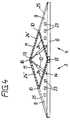
- the bridge sections 3 and 4each consist, in a known manner, of two parallel track tracks which are connected to one another via central struts or cross struts 23.
- Each trackhas two lower straps 8 extending over the entire length, to which, in the exemplary embodiment according to FIG. 4, a vertical triangular side wall 9 is connected at the top.
- a joint 10is arranged, which has an axis running horizontally and perpendicularly to the longitudinal direction of the bridge.
- a track section 11, which again consists of two parallel track tracks,is articulated on each bridge section 3, 4 so as to be pivotable about the joint 10.
- an inclined carriageway section 25is fixedly arranged for each track.
- Each lower flange 8is assigned a hydraulic cylinder 12, which is articulated with its extendable end at the end of the carriageway section 11 at a point 13 and with its other end in the region of the lower flange at a point 14.
- the ramp plates 33which are also articulated on the movable roadway sections 11, are folded down and supported against the lower flange 8 .
- the bridgeis moved in a known manner by means of the laying device 1 after the frame 5 has been extended.
- the lower chords 8 and the free ends of the carriageway sections 11each have the known coupling elements for coupling the bridge sections 3 and 4.
- the frame 5does not need to be extended due to the lower weight of the short bridges.
- the short bridgesare produced in a simple manner by retracting the hydraulic cylinders 12.
- the roadway sections 11are lowered and come to rest with their outer longitudinal edges on the side walls 9.
- toothings 24 and 24 ′are provided on the side walls 9 and on the roadway sections 11, as indicated in FIG. 4, in order to better distribute thrust forces over the length of the respective roadway section 11 or in the side walls 9 initiate. 4, the coupling elements 15 for the lower chords 8 and the coupling elements 16 for the roadway sections 11 are indicated.
- the central struts 23 for connecting the two track tracksare connected to the side walls 9.
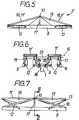
- FIG. 5shows a bridge section 3 ', the top of which consists of two adjoining road sections 11 'is formed, both of which can be pivoted about a joint 10 which is located at the top on a support 17 fastened to the lower flange 8.
- the joint 10is further stabilized in its position by a guy 18.
- the roadway sections 11 'have supports 19 for reinforcement, which can simultaneously form the side wall of the roadway section or the respective track of the roadway section.
- the carriers 19, which have a triangular shape,can lie against one another in the region of the joint 10 in the folded state and rest with their lower edges on the lower straps 8.
- the supports 19form supports which make the roadway sections 11 ′ rigid.
- the hydraulic cylinders 12are, as shown in FIG.
- This embodimentcan be used as a finished bridge (FIG. 5), as a bridge section with the same continuous height (FIG. 7) and also as a ramp section if one carriageway section 11 'is opened and the other is closed.
- the inner lower straps 8are expanded to form U-shaped rails 34.
- Groups of rollers 35are arranged on the laying device 1, only the main or central axis 36 of which is indicated in FIGS. 1 and 3. The rollers 35 engage in the rails 34 and allow the bridge sections 3, 4 to be moved or moved on the laying device 1.
- the bridge section 26 shown schematically in FIGS. 8 to 10has - like the bridge section 3 or 4 - a rigid and a foldable roadway section 27 or 11 "with respect to the upper side, but with the side also the rigid roadway section 27 is not ramp-like wedge-shaped, but is of a constant height.
- a bridge or ramp sectioncan be coupled again to the free end of the rigid part 20 with the roadway section 27.
- the foldable roadway section 11 "is folded in Fig. 8 and shown in Fig. 10 extended to its upper end position. 9 shows the position of the carriageway section 11 ′′ in a central position in which it can be fixed. In this position, an extension ramp 21 can be coupled by appropriate devices.
- the hydraulic cylinders 12 ′are in the central region of the carriageway section 11 "hinged to it so that the bridge field to be supported is halved.
- the bridge section 28 in the embodiment shown in FIG. 11, like the design according to FIGS. 5 to 7,has two foldable roadway sections 31, 32, which, however, have a rigid intermediate section 22 with a fixed roadway section 30 are interconnected, so that there are two joints 10 on the top of this bridge section 28.
- This embodimentlike that of FIG. 5, has the particular advantage that when using this bridge section as a ramp, the bridge section does not have to be rotated through 180 ° of the horizontal plane before laying.
Landscapes
- Engineering & Computer Science (AREA)
- Architecture (AREA)
- Civil Engineering (AREA)
- Structural Engineering (AREA)
- Bridges Or Land Bridges (AREA)
- Aerials With Secondary Devices (AREA)
- Auxiliary Methods And Devices For Loading And Unloading (AREA)
- Road Paving Structures (AREA)
- Input Circuits Of Receivers And Coupling Of Receivers And Audio Equipment (AREA)
- Details Of Aerials (AREA)
- Telephone Function (AREA)
- Internal Circuitry In Semiconductor Integrated Circuit Devices (AREA)
Abstract
Description
Translated fromGermanDie Erfindung bezieht sich auf eine verlegbare Brücke, die einen oder mehrere an der Oberseite mit einer Fahrbahn versehene Brücken-Abschnitte aufweist, und auf ein Verlegesystem.The invention relates to a layable bridge, which has one or more bridge sections provided with a roadway on the top, and a laying system.
Derartige Brücken, die meist als Pionierbrücken verwendet werden, werden in der Regel mit Hilfe eines mit einer Verlegereinrichtung versehenen Fahrzeugs über ein Hindernis (Fluß, Graben) geschoben und abgelegt, und in den meisten Fällen auch auf diesem Fahrzeug gleichzeitig transportiert. Die Brücken können - bezogen auf Ihre Längsrichtung - einteilig ausgebildet, d.h. aus nur einem einzigen Brücken-Abschnitt oder -Element bestehend, oder aus mehreren einzelnen Brücken-Abschnitten zusammengesetzt sein. Allen Brücken ist gemeinsam, daß an beiden Enden eine Rampe ausgebildet wird. Insbesondere bei den kürzeren Brücken dieser Art ergeben sich besondere Schwierigkeiten dadurch, daß nur eine bestimmte Brückenlänge auf einem Fahrzeug verladen werden kann, die dann am Einsatzort verfügbar ist, wobei oftmals nicht vorhersehbar ist, welche Brückenlänge gerade benötigt wird. So istz.B. aus der EP-B-0 093 873 eine aus zwei Rampenabschnitten zusammensetzbare Brücke bekannt, die auf einem Kraftfahrzeug transportiert wird und eine bestimmte Länge - in der Regel 26 m - aufweist. Andererseits wird in der DE-A-33 20 633 ein Brückenlegegerät beschrieben, bei dem auf einem Fahrzeug zwei jeweils 12 Meter messende Kurzbrücken transportiert und durch dieses einzeln verlegt werden können. Ein Zusammensetzen der beiden Kurzbrücken zu einer Brücke von doppelter Länge ist nicht möglich.Such bridges, which are mostly used as pioneering bridges, are usually pushed and deposited over an obstacle (river, ditch) with the aid of a vehicle provided with a laying device, and in most cases also transported on this vehicle at the same time. The bridges can - in relation to their longitudinal direction - be made in one piece, i.e. consist of only a single bridge section or element, or be composed of several individual bridge sections. All bridges have in common that a ramp is formed at both ends. Particularly with the shorter bridges of this type, particular difficulties arise from the fact that only a certain bridge length can be loaded on a vehicle, which is then available at the place of use, it often being impossible to predict which bridge length is currently required. For example, from EP-B-0 093 873 a bridge that can be assembled from two ramp sections is known, which is transported on a motor vehicle and has a certain length - generally 26 m. On the other hand, DE-A-33 20 633 describes a bridge-laying device in which two short bridges measuring 12 meters each can be transported on a vehicle and laid individually by this. It is not possible to assemble the two short bridges into a bridge of double length.
Aus der Veröffentlichung, "Internationales Wehrtechnisches Symposium 'Militärische Brücken', 28.-30. Juni 1988", Punkt 12 "Aktive mechanische Systeme im militärischen Brückenbau" von H. Baier, W. Charon (Fa. Dornier System), Friedrichshafen (DE), der Bundesakademie für Wehrtechnik, Mannheim, ist eine verlegbare Brücke bekannt, die aus an der Oberseite mit einer Fahrbahn versehenen Brücken-Abschnitten besteht. Jeder Brücken-Abschnitt weist einen Untergurt auf, in dessen Mitte eine Fahrbahnanordnung angelenkt ist, die - von der Seite gesehen - aus einer Fahrbahn und zwei in der Länge veränderbaren Stützstreben besteht, wobei die Stützstreben einerseits jeweils an einem Ende der Fahrbahn und andererseits gemeinsam in der Mitte des Untergurts angelenkt sind. Die durch die Fahrbahn und die Stützstreben gebildete dreieckförmige Konstruktion kann in ihrer Form verändert werden, wodurch auch die mittlere Höhe der mit einem Träger versehenen Fahrbahn gegenüber dem Untergurt einstellbar ist. Die dreieckförmige Konstruktion ist insgesamt um die Mitte des Untergurts schwenkbar, wodurch die Neigung der Fahrbahn mitbestimmt wird. Durch die Anlenkung der dreieckförmigen Konstruktion in nur einer Gelenkachse ist jeder einzelne Brücken-Abschnitt für sich nicht stabil. Eine Brücke muß deshalb aus mindestens zwei zusammengekoppelten Brücken-Abschnitten bestehen.From the publication, "International Defense Technical Symposium 'Military Bridges', June 28-30, 1988",
Aus der DE-A1-35 17 724 ist schließlich ein Verlegepanzer mit zwei "Kurzbrücken" ohne schwenkbare Fahrbahn-Abschnitte bekannt, die am Untergurt U-förmige Laufschienen aufweisen, in denen Stützrollen des Verlegepanzers eingreifen.From DE-A1-35 17 724, finally, an installation armor with two "short bridges" without pivotable roadway sections is known, which have U-shaped rails on the lower flange, in which support rollers of the installation armor engage.
Aus der älteren EP-Patentanmeldung 89 403 399.2 (EP-A-0 374 019) ist eine aus einem Brücken-Abschnitt bestehende oder aus mehreren Brücken-Abschnitten zusammengesetzte verlegbare Brücke bekannt, bei der der bzw. jeder Brücken-Abschnitt über seine ganze Länge einen festen Untergurt aufweist und mit einem Fahrbahn-Abschnitt versehen ist, der die halbe Länge des Brücken-Abschnitts einnimmt und um eine senkrecht zur Brückenlängsrichtung verlaufende horizontale Achse schwenkbar gelagert ist. Die Brücken-Abschnitte können einzeln mit heruntergeklappter beweglicher Fahrbahn ein schmales Hindernis überspannen. Es können aber auch zwei miteinander gekuppelte Brücken-Abschnitte zusammen ein breiteres Hindernis überspannen, wobei bei den gekuppelten Enden der Brücken-Abschnitte die bewegbaren Fahrbahn-Abschnitte hochgeklappt und abgestützt sind. Beim Verlegen der Brücken-Abschnitte gleiten diese auf Gleitkissen einer Verlegeeinrichtung, was eine erhebliche Breite der Verlegeeinrichtung bedingt. Lediglich zum Aufbringen eines Gegenmomentes bei überhängendem Brücken-Abschnitt ist dieser an seinem hinteren Ende mit Rollen versehen, die in Führungsnuten der Verlegeeinrichtung eingreifen.From the earlier EP patent application 89 403 399.2 (EP-A-0 374 019) a bridge consisting of a bridge section or composed of several bridge sections is known, in which the or each bridge section over its entire length has a fixed lower flange and is provided with a roadway section which occupies half the length of the bridge section and is pivotably mounted about a horizontal axis running perpendicular to the longitudinal direction of the bridge. The bridge sections can individually span a narrow obstacle with the movable roadway folded down. However, two bridge sections that are coupled together can also span a wider obstacle, the movable roadway sections being folded up and supported at the coupled ends of the bridge sections. When laying the bridge sections, they slide on sliding pads of a laying device, which requires a considerable width of the laying device. Only to apply a counter torque in the case of an overhanging bridge section is provided at its rear end with rollers which engage in guide grooves in the laying device.
Der Erfindung liegt die Aufgabe zugrunde, eine verlegbare Brücke der eingangs genannten Art so zu gestalten, daß insbesondere die auf einem Fahrzeug mitgeführten Brücken-Abschnitte den Bau von Brücken verschiedener Längen ermöglichen.The invention has for its object to design a relocatable bridge of the type mentioned so that in particular the bridge sections carried on a vehicle enable the construction of bridges of different lengths.
Diese Aufgabe wird erfindungsgemäß dadurch gelöst, daß der Brücken-Abschnitt über seine ganze Länge mindestens einen festen Untergurt aufweist und mit mindestens einem eine horizontal und senkrecht zur Brückenlängsrichtung verlaufende Achse aufweisenden Gelenk versehen ist, das über Seitenwände, Stützen od. dgl. fest in Bezug auf den Untergurt angeordnet ist und um welches ein im Endbereich des Brücken-Abschnitts befindlicher Fahrbahn-Abschnitt schwenkbar ist, der einen Teil der Länge des Brücken-Abschnitts ausmacht, und daß an dem Untergurt Laufschienen angeordnet sind. Die Fahrbahn und der Fahrbahn-Abschnitt, der nur einen Teil der Länge des Brücken-Abschnitts ausmacht, können einteilig oder- wie bei Pionierbrücken in der Regel vorgesehen - als zwei parallel Spurbahnen ausgebildet sein. Durch die an dem Untergurt angeordneten Laufschienen kann der Brücken-Abschnitt auf einer Verlegeeinrichtung verfahren werden. Anstatt Laufschienen am Untergurt anzubringen, kann dieser auch in Form von Laufschienen ausgebildet sein.This object is achieved in that the bridge section has at least one fixed lower flange over its entire length and is provided with at least one joint having a horizontal and perpendicular axis to the longitudinal direction of the bridge, which is fixed in relation to side walls, supports or the like is arranged on the lower chord and around which a roadway section located in the end region of the bridge section, which makes up part of the length of the bridge section, can be pivoted, and that running rails are arranged on the lower chord. The roadway and the roadway section, which only makes up part of the length of the bridge section, can be designed in one piece or - as is usually provided for pioneer bridges - as two parallel track lines. Due to the running rails arranged on the lower flange, the bridge section can be moved on a laying device. Instead of attaching rails to the lower flange, this can also be designed in the form of rails.
Die Erfindung ermöglicht eine Vielzahl von verschiedenen Ausbildungen der Brücken-Abschnitte und damit verbunden die Bildung einer größeren Anzahl von verschiedenen Brückenlängen unter Verwendung von wenigen Brücken-Abschnitten.The invention enables a large number of different configurations of the bridge sections and, associated therewith, the formation of a greater number of different bridge lengths using a few bridge sections.
Vorteilhafte Weiterbildungen der Erfindung sind in den Unteransprüchen beschrieben. Eine besonders vorteilhafte Kontruktion für die neuen Brücken-Abschnitte ergibt sich daraus, daß das Gelenk im Bereich der Oberseite der Fahrbahn angeordnet ist und daß dabei der Fahrbahnabschnitt mit mindestens einem Träger versehen ist. Der Träger kann dabei gleichzeitig die Seitenwände des Fahrbahnabschnitts bilden, so daß sich für den Querschnitt des Fahrbahnabschnitts eine tragfähige U-Form ergibt.Advantageous developments of the invention are described in the subclaims. A particularly advantageous design for the new bridge sections results from the fact that the joint is arranged in the region of the top of the carriageway and that the carriageway section is provided with at least one carrier. The carrier can simultaneously form the side walls of the carriageway section, so that there is a stable U-shape for the cross section of the carriageway section.
Der angelenkte Fahrbahn-Abschnitt soll vorzugsweise mindestens in seinen Endstellungen feststellbar sein, um die Brücke im Lastfall zu versteifen. Auftretende Schubspannungen können auf einfache Weise in Brückenlängsrichtung dadurch verteilt werden, daß die Feststellung in der unteren Stellung des Fahrbahn-Abschnitts durch den Eingriff einer Verzahnung gebildet ist.The articulated section of the carriageway should preferably be lockable at least in its end positions in order to stiffen the bridge in the event of a load. Shear stresses that occur can be distributed in a simple manner in the longitudinal direction of the bridge in that the determination in the lower position of the roadway section is formed by the engagement of a toothing.
Als Verstelleinrichtungen eignen sich insbesondere Linear-Motore, vorzugsweise Hydrozylinder, die insbesondere auch zur Aufnahme größerer Lasten geeignet sind.Linear motors, preferably hydraulic cylinders, are particularly suitable as adjusting devices, which are also particularly suitable for absorbing larger loads.
Besonders geeignet für die Bildung von Kurzbrücken ist eine Ausführungsform, bei der der Brücken-Abschnitt zwei rampenförmige Bereiche aufweist, von denen mindestens einer als schwenkbarer Fahrbahn-Abschnitt ausgebildet ist. Hierbei ergeben sich besondere Vorteile, wenn zwei solcher Brücken-Abschnitte übereinander auf einem Verlegefahrzeug verlastbar und mit hochgeschwenkten Fahrbahn-Abschnitten an diesen miteinander koppelbar sind. Die verlasteten Brücken-Abschnitte können somit zwei Kurzbrücken bilden oder zu einer doppelt so langen Brücke zusammengesetzt werden.An embodiment is particularly suitable for the formation of short bridges, in which the bridge section has two ramp-shaped areas, at least one of which is designed as a pivotable roadway section is trained. This has particular advantages if two such bridge sections can be loaded one above the other on a laying vehicle and can be coupled to one another with the roadway sections pivoted upwards. The loaded bridge sections can thus form two short bridges or be combined to form a bridge twice as long.
In der Zeichnung sind mehrere Ausführungsbeispiele der Erfindung schematisch dargestellt, die anschließend näher erläutert werden. Es zeigen:
- Fig. 1 bis 3
- einen Brückenleger des Typs, wie er in der EP-B-0 093 873 offenbart ist, in drei verschiedenen Stellungen der verlasteten Brückenteile jeweils in Ansicht,
- Fig. 4
- eine solche aus zwei Abschnitten zusammengesetzte Brücke in Ansicht,
- Fig. 5
- eine andere Ausführungsform eines Brücken-Abschnitts in Ansicht,
- Fig. 6
- einen Schnitt nach der Linie VI-VI in Fig. 7,
- Fig. 7
- den Brücken-Abschnitt nach Fig.5 mit hochgeklappten Fahrbahn abschnitten,
- Fig. 8 bis 10
- eine weitere Ausführungsform eines Brückenabschnitts in drei verschiedenen Stellungen in Ansicht und
- Fig. 11
- - ebenfalls in Ansicht - ein erneut abgeändertes Ausführungsbeispiel einer neuen Brücke bzw. eines Brücken-Abschnitts.
- 1 to 3
- a bridge layer of the type as disclosed in EP-B-0 093 873, in three different positions of the loaded bridge parts, each in view,
- Fig. 4
- such a bridge made up of two sections in view,
- Fig. 5
- another embodiment of a bridge section in view,
- Fig. 6
- 7 shows a section along the line VI-VI in FIG. 7,
- Fig. 7
- cut the bridge section according to Fig. 5 with the roadway folded up,
- 8 to 10
- a further embodiment of a bridge section in three different positions in view and
- Fig. 11
- - also in view - another modified embodiment of a new bridge or a bridge section.
Wie aus Fig. 1 zu ersehen, trägt das an seinem hinteren Ende mit einer Verlegeeinrichtung 1 versehene Fahrzeug 2 zwei jeweils gleichgestaltete Brücken-Elemente oder -Abschnitte 3 und 4, die auf einem zum rückwärtigen Ende des Fahrzeugs 2 hin ausschiebbaren Rahmengestell 5 übereinanderliegen. Das Rahmengestell 5 trägt auch die Verlegeeinrichtung 1 und ist ferner an seinem freien Ende mit nach unten hin ausfahrbaren Bodenabstützelementen 6 versehen. Zum Verlegen der Brückenteile dient auch ein am vorderen Ende des Rahmengestells 5 angelenkter Hebel 7.As can be seen from FIG. 1, the
Die Brücken-Abschnitte 3 und 4 bestehen in bekannter Weise jeweils aus zwei parallel verlaufenden Spurbahnen, die über Mittelstreben oder Querstreben 23 miteinander verbunden sind. Jede Spurbahn weist zwei über die ganze Länge reichende Untergurte 8 auf, an die sich bei dem Ausführungsbeispiel nach Fig. 4 nach oben hin jeweils eine senkrechte dreieckförmige Seitenwand 9 anschließt. Im Bereich der Spitze dieses nach oben weisenden Dreiecks ist ein Gelenk 10 angeordnet, welches eine horizontal und senkrecht zur Brückenlängsrichtung verlaufende Achse aufweist. Um das Gelenk 10 schwenkbar ist an jedem Brücken-Abschnitt 3, 4 ein Fahrbahn-Abschnitt 11, der ebenfalls wieder aus zwei parallelen Spurbahnen besteht, angelenkt. Zwischen der Achse des Gelenks 10 und dem dem schwenkbaren Fahrbahn-Abschnitt 11 gegenüberliegenden Ende des Brücken-Abschnitts 3 bzw. 4 ist - für jede Spurbahn getrennt - ein schräger Fahrbahn-Abschnitt 25 fest angeordnet.The
Jedem Untergurt 8 ist ein Hydraulikzylinder 12 zugeordnet, der mit seinem ausfahrbaren Ende jeweils am Ende des Fahrbahn-Abschnitts 11 in einem Punkt 13 und mit seinem anderen Ende im Bereich des Untergurts in einem Punkt 14 angelenkt ist.Each
Im verladenen Zustand der Brücken-Abschnitte 3, 4 sind die Hydraulikzylinder 12 soweit ausgefahren, daß der feste Fahrbahn-Abschnitt 25 mit dem jeweiligen schwenkbaren Fahrbahn-Abschnitt 11 jeweils in einer Ebene liegt (vgl. Fig. 1 und 2). In diesem Zustand sind zwei fertige Brücken-Abschnitte 3, 4 gebildet, die mittels der Verlegereinrichtung 1 auf dem Fahrzeug 2 verfahren und zu einer langen Brücke zusammengesetzt werden können, wie aus Fig. 2 hervorgeht.In the loaded state of the
Zum Feststellen der beweglichen Fahrbahn-Abschnitte 11 in ihrer oberen Endstellung und damit zum Versteifen einer aus zwei solcher Brücken-Abschnitte 3, 4 zusammengesetzten Brücke werden die auch an den beweglichen Fahrbahn-Abschnitten 11 angelenkten Rampenplatten 33 nach unten geklappt und gegen den Untergurt 8 abgestütz.To fix the
Die Brücke wird mittels der Verlegereinrichtung 1 nach Ausfahren des Rahmengestells 5 in bekannter Weise verlegt. Die Untergurte 8 und die freien Enden der Fahrbahn- Abschnitte 11 weisen zum Koppeln der Brücken-Abschnitte 3 und 4 jeweils die bekannten Kopplungs-Elemente auf.The bridge is moved in a known manner by means of the laying device 1 after the
Fig. 3 zeigt die alternative Verlegemöglichkeit von zwei Kurzbrücken, die dementsprechend die halbe Länge aufweisen und einzeln durch die Verlegereinrichtung 1 verlegt werden können. Für den Verlegevorgang braucht das Rahmengestell 5 wegen des geringeren Gewichts der Kurzbrücken nicht ausgefahren zu werden. Die Kurzbrücken werden in einfacher Weise durch Einfahren der Hydraulikzylinder 12 hergestellt. Dabei werden die Fahrbahn-Abschnitte 11 abgesenkt und kommen mit ihren äußeren Längskanten auf den Seitenwänden 9 zur Anlage. Dabei sind an den Seitenwänden 9 und an den Fahrbahn-Abschnitten 11 Verzahnungen 24 bzw. 24' vorgesehen, wie sie in Fig. 4 angedeutet sind, um Schubkräfte besser auf die Länge des jeweiligen Fahrbahn-Abschnitts 11 zu verteilen bzw. in die Seitenwände 9 einzuleiten. In Fig. 4 sind ferner die Kopplungselemente 15 für die Untergurte 8 und die Kopplungselemente 16 für die Fahrbahn-Abschnitte 11 angedeutet. Die Mittelstreben 23 zum Verbinden der beiden Spurbahnen sind mit den Seitenwänden 9 verbunden.3 shows the alternative possibility of laying two short bridges, which accordingly have half the length and can be laid individually by the laying device 1. For the laying process, the
Fig.5 zeiteinen Brücken-Abschnitt 3', dessen Oberseite aus zwei aneinander anschließenden Fahrbahn-Abschnitten 11' gebildet ist, die beide um ein Gelenk 10 schwenkbar sind, das sich oben an einer am Untergurt 8 befestigten Stütze 17 befindet. Das Gelenk 10 wird ferner durch eine Abspannung 18 in seiner Lage stabilisiert. Die Fahrbahn-Abschnitte 11' weisen zur Verstärkung Träger 19 auf, die gleichzeitig die Seitenwand des Fahrbahn-Abschnitts bzw. der jeweiligen Spurbahn des Fahrbahn-Abschnitts bilden können. Die eine Dreieckform aufweisenden Träger 19 können im zusammengeklappten Zustand im Bereich des Gelenks 10 aneinanderliegen und mit ihren unteren Kanten auf den Untergurten 8 aufliegen. Wie aus Fig. 7 erkennbar, bilden die Träger 19 Unterstützungen, die die Fahrbahn-Abschnitte 11' biegesteif gestalten. Die Hydraulikzylinder 12 sind, wie es Fig. 6 zeigt, an den - bezogen auf die Spurbahnen - Innenseiten der Untergurte 8 angelenkt. Diese Ausführungsform kann als fertige Brücke (Fig. 5), als Brücken-Abschnitt mit gleicher durchgehender Höhe (Fig. 7) sowie auch als Rampen-Abschnitt eingesetzt werden, wenn ein Fahrbahn-Abschnitt 11' aufgeklappt und der andere eingeklappt ist.5 shows a bridge section 3 ', the top of which consists of two adjoining road sections 11 'is formed, both of which can be pivoted about a joint 10 which is located at the top on a
Aus Fig. 6 ist weiter ersichtlich, daß (dies gilt auch für die übrigen Ausführungsbeispiele) die innen angeordneten Untergurte 8 zu U-förmigen Laufschienen 34 erweitert sind. An der Verlegeeinrichtung 1 sind Gruppen von Laufrollen 35 angeordnet, von denen in den Fig. 1 und 3 lediglich deren Haupt- oder Mittelachse 36 angedeutet ist. Die Laufrollen 35 greifen in die Laufschienen 34 ein und ermöglichen ein Verschieben bzw. Verfahren der Brücken-Abschnitte 3, 4 auf der Verlegeeinrichtung 1.From Fig. 6 it can further be seen that (this also applies to the other exemplary embodiments) the inner
Der in den Fig. 8 bis 10 schematisch dargestellte Brücken-Abschnitt 26 weist - wie der Brücken-Abschnitt 3 oder 4 - im Hinblick auf die Oberseite einen starren und einen klappbaren Fahrbahn-Abschnitt 27 bzw. 11" auf, wobei jedoch die Seite mit dem starren Fahrbahn-Abschnitt 27 nicht rampenartig keilförmig, sondern mit gleichbleibender Höhe ausgebildet ist. An das freie Ende des starren Teils 20 mit dem Fahrbahn-Abschnitt 27 kann wieder ein Brücken- oder Rampen-Abschnitt angekuppelt werden. Der klappbare Fahrbahn-Abschnitt 11" ist in Fig. 8 eingeklappt und in Fig. 10 bis in seine obere Endstellung ausgeklappt gezeigt. Fig. 9 zeigt die Lage des Fahrbahn- Abschnitts 11" in einer Mittelstellung, in der er festsetzbar ist. In dieser Stellung kann durch entsprechende Einrichtungen eine Verlängerungs- Rampe 21 angekuppelt werden. Die Hydraulikzylinder 12' sind im mittleren Bereich des Fahrbahn- Abschnitts 11" an diesem angelenkt, so daß das zu unterstützende Brückenfeld halbiert wird.The
Der Brücken-Abschnitt 28 in der in Fig. 11 gezeigten Ausführungsform weist - wie die Ausbildung nach Fig.5 bis 7 - zwei klappbare Fahrbahn-Abschnitte 31, 32 auf, die jedoch über ein starres, zwischengeschaltetes Mittelteil 22 mit festem Fahrbahn-Abschnitt 30 miteinander verbunden sind, so daß sich an der Oberseite dieses Brücken-Abschnitts 28 zwei Gelenke 10 ergeben. Diese Ausführungsform weist, wie die nach Fig. 5, insbesondere den Vorteil auf, daß bei Verwendung dieses Brücken-Abschnitts als Rampe der Brücken-Abschnitt vor dem Verlegen nicht erst um 180° der horizontalen Ebene gedreht werden muß.The
Claims (10)
- Portable bridge having one or more bridge sections provided with a carriageway on the upper side,
characterised by
the bridge section (3, 4; 3'; 26; 28) having at least one fixed bottom chord (8) over ist entire length, and provided with at least one articulation (10) with a horizontal axis perpendicular tok the logitudinal direction of the bridge, the articulation being permanently arranged with respect to the bottom chord (8) via side walls (9), supports (17) or the like and on which one carriageway section (11; 11'; 11"; 31) extending over part of the length of the bridge section (3, 4; 3'; 26, 28) and located in the end zone of the bridge section can be tilted, and that rails (34) are arranged on the bottom chord (8). - Bridge as claim 1, characterised by the articulation (10) being arranged in the zone of the upper side of the carriageway.
- Bridge as claims 1 or 2, characterised by the carriageway section (11; 11'; 11"; 31, 32) being provided with at least one support (19).
- Bridge as claim 3, characterized by the support (19) forming at least one side wall of the carriageway section (11; 11'; 11"; 31, 32).
- Bridge as one of the preceding claims, characterised by the carriageway section (11; 11'; 11"; 31, 32) being locked in its final positions.
- Bridge as claim 5, characterised by designing the locking of the tilting carriadgeway section (11; 11'; 11"; 31. 32) In its lower position by engaging a gear tooth system (24, 24').
- Bridge as one of the preceding claims, characterised by the use of at least one linear motor, preferably a hydrocylinder (12, 12') as adjusting mechanism for tilting the carriageway section (11; 11'; 11"; 31, 32).
- Bridge as claim 7, characterised by the linear motor (12) acting on the carriageway (11; 11') in an articulated manner In the zone of its free end.
- Bridge as one of the claims 1 to 8, characterised by the bridge section (3, 4; 3') having two ramp-form end zones, of which at least one is designed as a tilting carriageway section (11; 11').
- Bridge laying system for a bridge as one of the claims 1 to 9, characterised by the two bridge sections (3, 4) being loaded on a laying vehicle (2) and coupled together one over the other at the carriageway sections (11) being tilted up.
Priority Applications (1)
| Application Number | Priority Date | Filing Date | Title |
|---|---|---|---|
| AT90105406TATE90127T1 (en) | 1989-04-07 | 1990-03-22 | DEPLOYABLE BRIDGE AND SYSTEM FOR DEPLOYING THE BRIDGE. |
Applications Claiming Priority (2)
| Application Number | Priority Date | Filing Date | Title |
|---|---|---|---|
| DE3911266ADE3911266A1 (en) | 1989-04-07 | 1989-04-07 | LAYABLE BRIDGE AND SYSTEM FOR LAYING THE BRIDGE |
| DE3911266 | 1989-04-07 |
Publications (4)
| Publication Number | Publication Date |
|---|---|
| EP0391149A2 EP0391149A2 (en) | 1990-10-10 |
| EP0391149A3 EP0391149A3 (en) | 1990-12-05 |
| EP0391149B1 EP0391149B1 (en) | 1993-06-02 |
| EP0391149B2true EP0391149B2 (en) | 1996-02-28 |
Family
ID=6378064
Family Applications (1)
| Application Number | Title | Priority Date | Filing Date |
|---|---|---|---|
| EP90105406AExpired - LifetimeEP0391149B2 (en) | 1989-04-07 | 1990-03-22 | Portable bridge and system for placing the bridge |
Country Status (5)
| Country | Link |
|---|---|
| US (1) | US5063630A (en) |
| EP (1) | EP0391149B2 (en) |
| AT (1) | ATE90127T1 (en) |
| DE (2) | DE3911266A1 (en) |
| ES (1) | ES2041066T3 (en) |
Cited By (3)
| Publication number | Priority date | Publication date | Assignee | Title |
|---|---|---|---|---|
| DE102007041579A1 (en)* | 2007-09-01 | 2009-04-09 | General Dynamics Santa Bárbara Sistemas GmbH | Hitch for transporting and laying military bridges |
| DE202009015857U1 (en) | 2009-11-19 | 2010-03-25 | General Dynamics European Land Systems-Germany Gmbh | Attachment for laying military bridges |
| DE102010055574A1 (en) | 2010-12-21 | 2012-06-21 | General Dynamics European Land Systems-Germany Gmbh | Modular bridge element |
Families Citing this family (14)
| Publication number | Priority date | Publication date | Assignee | Title |
|---|---|---|---|---|
| DE4127106C2 (en)* | 1991-08-16 | 1994-12-08 | Gutehoffnungshuette Man | Mobile bridge laying device |
| DE4305764A1 (en)* | 1993-02-25 | 1994-09-01 | Krupp Foerdertechnik Gmbh | Layable bridge and device for laying the bridge |
| EP0640723B1 (en)* | 1993-08-31 | 1998-09-16 | Krupp Fördertechnik GmbH | Portable bridge |
| EP0640722A1 (en)* | 1993-08-31 | 1995-03-01 | Krupp Fördertechnik GmbH | Portable bridge |
| US5504956A (en)* | 1994-09-23 | 1996-04-09 | Fordertechnik Gmbh | Guide groove at bridge sections or the like of portable bridges and method for repairing the same |
| DE19724771C1 (en)* | 1997-06-12 | 1998-10-01 | Dornier Gmbh | Modular bridge structure |
| DE19750490A1 (en) | 1997-11-14 | 1999-05-27 | Ewk Gmbh | Bridge element for the formation of bridges which can be laid by means of a laying vehicle |
| DE10127136B4 (en)* | 2001-06-02 | 2010-07-15 | General Dynamics Santa Bárbara Sistemas GmbH | Military quick-build bridge system |
| DE102004049969B8 (en)* | 2004-10-14 | 2006-03-23 | Military Mobile Bridges Gmbh | Modular scissor bridge and installation device and method for laying collapsible bridges |
| DE102006042251A1 (en)* | 2006-09-08 | 2008-03-27 | General Dynamics Santa Bárbara Sistemas GmbH | bridge element |
| US20100281635A1 (en)* | 2009-05-05 | 2010-11-11 | Tactical & Rescue Gear, Ltd. | Connection assembly for a modular footbridge |
| CN103938535B (en)* | 2014-05-18 | 2016-01-20 | 虞萍萍 | Be arranged on the fastening devices in interim overline bridge column |
| DE102017100815A1 (en)* | 2017-01-17 | 2018-07-19 | Krauss-Maffei Wegmann Gmbh & Co. Kg | Bridge laying device for laying a particular one-piece bridge |
| CN113699900B (en)* | 2021-09-10 | 2023-01-03 | 中铁第五勘察设计院集团有限公司 | Beam pier structure for bridge emergency repair and application thereof |
Family Cites Families (12)
| Publication number | Priority date | Publication date | Assignee | Title |
|---|---|---|---|---|
| DE151730C (en)* | ||||
| DE1816876A1 (en)* | 1968-12-24 | 1971-05-27 | Welz Hans Joachim Dipl Ing | Component for the production of transportable bridges, runways, containers or the like. |
| DE1945676A1 (en)* | 1969-09-10 | 1971-03-11 | Krupp Gmbh | Components for dismountable bridges and the superstructure of such |
| SU837994A1 (en)* | 1979-09-26 | 1981-06-15 | Okulov Pavel D | Span structure of power-operated bridge |
| FR2495657A1 (en)* | 1980-08-21 | 1982-06-11 | France Etat | AUTOMATIC ASSEMBLY DEVICE CLOSING TWO BRIDGE ELEMENTS AND BRIDGE ELEMENT COMPRISING SAME |
| US4521932A (en)* | 1981-12-08 | 1985-06-11 | Fairey Engineering Limited | Transportable bridge structure |
| DE3217435A1 (en)* | 1982-05-08 | 1983-11-17 | IBEK Ingenieurbüro Echtler Kaiserslautern GmbH, 6750 Kaiserslautern | MOTOR VEHICLE FOR TRANSPORTING AND LAYING A FIXED BRIDGE |
| US4534079A (en)* | 1982-06-17 | 1985-08-13 | The Secretary Of State For Defence In Her Britannic Majesty's Government Of The United Kingdom Of Great Britain And Northern Ireland | Transportable folding bridge |
| DE3320633A1 (en)* | 1983-06-08 | 1984-12-13 | Dornier System Gmbh, 7990 Friedrichshafen | Bridge-laying device |
| DE3628273A1 (en)* | 1986-08-20 | 1988-03-03 | Krupp Gmbh | INSTALLATION SYSTEM FOR A DISASSEMBLABLE BRIDGE |
| GB8623184D0 (en)* | 1986-09-26 | 1986-10-29 | Steadman B | Structures |
| IT1226581B (en)* | 1988-08-02 | 1991-01-24 | Reiter & Crippa Ind S P A | BRIDGE, RAMP AND SIMILAR OF SELF-ASSEMBLING TYPE |
- 1989
- 1989-04-07DEDE3911266Apatent/DE3911266A1/ennot_activeWithdrawn
- 1990
- 1990-03-22ESES199090105406Tpatent/ES2041066T3/ennot_activeExpired - Lifetime
- 1990-03-22EPEP90105406Apatent/EP0391149B2/ennot_activeExpired - Lifetime
- 1990-03-22DEDE9090105406Tpatent/DE59001588D1/ennot_activeExpired - Lifetime
- 1990-03-22ATAT90105406Tpatent/ATE90127T1/ennot_activeIP Right Cessation
- 1990-04-06USUS07/505,690patent/US5063630A/ennot_activeExpired - Fee Related
Cited By (7)
| Publication number | Priority date | Publication date | Assignee | Title |
|---|---|---|---|---|
| DE102007041579A1 (en)* | 2007-09-01 | 2009-04-09 | General Dynamics Santa Bárbara Sistemas GmbH | Hitch for transporting and laying military bridges |
| DE102007041579B4 (en)* | 2007-09-01 | 2009-07-30 | General Dynamics Santa Bárbara Sistemas GmbH | Hitch for transporting and laying military bridges |
| US7568252B2 (en) | 2007-09-01 | 2009-08-04 | General Dynamics European Land Systems-Germany Gmbh | Attachments for transporting and launching military bridges |
| DE202009015857U1 (en) | 2009-11-19 | 2010-03-25 | General Dynamics European Land Systems-Germany Gmbh | Attachment for laying military bridges |
| DE102010055574A1 (en) | 2010-12-21 | 2012-06-21 | General Dynamics European Land Systems-Germany Gmbh | Modular bridge element |
| WO2012084230A1 (en)* | 2010-12-21 | 2012-06-28 | General Dynamics European Land Systems-Germany Gmbh | Modular bridge element |
| DE102010055574B4 (en)* | 2010-12-21 | 2012-08-09 | General Dynamics European Land Systems-Germany Gmbh | Modular bridge element |
Also Published As
| Publication number | Publication date |
|---|---|
| DE59001588D1 (en) | 1993-07-08 |
| ES2041066T3 (en) | 1993-11-01 |
| EP0391149A2 (en) | 1990-10-10 |
| EP0391149A3 (en) | 1990-12-05 |
| DE3911266A1 (en) | 1990-10-11 |
| ATE90127T1 (en) | 1993-06-15 |
| EP0391149B1 (en) | 1993-06-02 |
| US5063630A (en) | 1991-11-12 |
Similar Documents
| Publication | Publication Date | Title |
|---|---|---|
| EP0391149B2 (en) | Portable bridge and system for placing the bridge | |
| DE4419203C2 (en) | Bridge composed of longitudinal beam sections, cross beams and road slabs | |
| DE2459497A1 (en) | TRANSPORTABLE BRIDGE | |
| EP0523757B1 (en) | Portable bridge | |
| DE68908893T2 (en) | FOLDABLE TRANSPORTABLE BRIDGE. | |
| EP0612886B1 (en) | Portable bridge and device for placing the bridge | |
| DE7415898U (en) | BRIDGING DEVICE FOR AN EXPANSION JOINT IN A ROAD | |
| DE9116635U1 (en) | Switch transport wagon | |
| DE2550030B1 (en) | Tunnel shuttering with support carriage - has adjustable flexible panelling on support and extensible bearers off main frame | |
| EP0916769A1 (en) | Bridge element for making portable bridges with a laying vehicle | |
| DE69003230T2 (en) | Modular bridge system and method for laying it. | |
| DE60021591T2 (en) | STRUCTURE FOR PROTECTING A STAGE STRUCTURE | |
| DE102004016983B4 (en) | Bridge laying device | |
| DE2931243C2 (en) | Switch for trough-like roads | |
| DE3027090A1 (en) | Level crossing prefab. reinforced concrete railway slabs - have supporting elastic layer, and protruding connecting rods hinged to rail | |
| DE3719508C2 (en) | ||
| DE2146286C2 (en) | Weather and privacy shield | |
| DE102010055574B4 (en) | Modular bridge element | |
| EP0798419A1 (en) | Accessible and/or practicable device | |
| DE3017048A1 (en) | Expansion joint cover for bridges - has intermediate cross member supported on rubber blocks mounted on cantilevers | |
| DE19625819A1 (en) | Device that can be walked on and / or driven over | |
| DE2422892C3 (en) | Support for a temporary bridge | |
| DE19719300A1 (en) | Trough bridge formed from segments | |
| DE2541095A1 (en) | Structural variable height joint gap spanning device - with lamellae stems linked to one edge by sliding rods | |
| DE3240819A1 (en) | DEVICE FOR RESTRAINING SUBSTANCES TRANSPORTED IN BUCKETS ON TRUCKS |
Legal Events
| Date | Code | Title | Description |
|---|---|---|---|
| PUAI | Public reference made under article 153(3) epc to a published international application that has entered the european phase | Free format text:ORIGINAL CODE: 0009012 | |
| AK | Designated contracting states | Kind code of ref document:A2 Designated state(s):AT CH DE ES FR GB IT LI SE | |
| PUAL | Search report despatched | Free format text:ORIGINAL CODE: 0009013 | |
| AK | Designated contracting states | Kind code of ref document:A3 Designated state(s):AT CH DE ES FR GB IT LI SE | |
| 17P | Request for examination filed | Effective date:19901208 | |
| 17Q | First examination report despatched | Effective date:19911223 | |
| GRAA | (expected) grant | Free format text:ORIGINAL CODE: 0009210 | |
| AK | Designated contracting states | Kind code of ref document:B1 Designated state(s):AT CH DE ES FR GB IT LI SE | |
| PG25 | Lapsed in a contracting state [announced via postgrant information from national office to epo] | Ref country code:GB Effective date:19930602 | |
| REF | Corresponds to: | Ref document number:90127 Country of ref document:AT Date of ref document:19930615 Kind code of ref document:T | |
| GBT | Gb: translation of ep patent filed (gb section 77(6)(a)/1977) | Effective date:19930609 | |
| REF | Corresponds to: | Ref document number:59001588 Country of ref document:DE Date of ref document:19930708 | |
| ET | Fr: translation filed | ||
| ITF | It: translation for a ep patent filed | ||
| REG | Reference to a national code | Ref country code:ES Ref legal event code:FG2A Ref document number:2041066 Country of ref document:ES Kind code of ref document:T3 | |
| PGFP | Annual fee paid to national office [announced via postgrant information from national office to epo] | Ref country code:CH Payment date:19940211 Year of fee payment:5 | |
| PLBI | Opposition filed | Free format text:ORIGINAL CODE: 0009260 | |
| PGFP | Annual fee paid to national office [announced via postgrant information from national office to epo] | Ref country code:AT Payment date:19940225 Year of fee payment:5 | |
| 26 | Opposition filed | Opponent name:DORNIER GMBH Effective date:19940219 | |
| EAL | Se: european patent in force in sweden | Ref document number:90105406.4 | |
| PGFP | Annual fee paid to national office [announced via postgrant information from national office to epo] | Ref country code:GB Payment date:19950213 Year of fee payment:6 | |
| PGFP | Annual fee paid to national office [announced via postgrant information from national office to epo] | Ref country code:SE Payment date:19950221 Year of fee payment:6 | |
| PGFP | Annual fee paid to national office [announced via postgrant information from national office to epo] | Ref country code:ES Payment date:19950313 Year of fee payment:6 | |
| PG25 | Lapsed in a contracting state [announced via postgrant information from national office to epo] | Ref country code:AT Effective date:19950322 | |
| PG25 | Lapsed in a contracting state [announced via postgrant information from national office to epo] | Ref country code:SE Free format text:LAPSE BECAUSE OF NON-PAYMENT OF DUE FEES Effective date:19950323 | |
| PG25 | Lapsed in a contracting state [announced via postgrant information from national office to epo] | Ref country code:LI Effective date:19950331 Ref country code:CH Effective date:19950331 | |
| REG | Reference to a national code | Ref country code:CH Ref legal event code:PL | |
| PUAH | Patent maintained in amended form | Free format text:ORIGINAL CODE: 0009272 | |
| STAA | Information on the status of an ep patent application or granted ep patent | Free format text:STATUS: PATENT MAINTAINED AS AMENDED | |
| 27A | Patent maintained in amended form | Effective date:19960228 | |
| AK | Designated contracting states | Kind code of ref document:B2 Designated state(s):AT CH DE ES FR GB IT LI SE | |
| RAP2 | Party data changed (patent owner data changed or rights of a patent transferred) | Owner name:KRUPP FOERDERTECHNIK GMBH | |
| REG | Reference to a national code | Ref country code:CH Ref legal event code:AEN Free format text:AUFRECHTERHALTUNG DES PATENTES IN GEAENDERTER FORM | |
| PG25 | Lapsed in a contracting state [announced via postgrant information from national office to epo] | Ref country code:ES Free format text:LAPSE BECAUSE OF THE APPLICANT RENOUNCES Effective date:19960323 | |
| ET3 | Fr: translation filed ** decision concerning opposition | ||
| GBV | Gb: ep patent (uk) treated as always having been void in accordance with gb section 77(7)/1977 [no translation filed] | Effective date:19930602 | |
| PGFP | Annual fee paid to national office [announced via postgrant information from national office to epo] | Ref country code:FR Payment date:19990216 Year of fee payment:10 | |
| PGFP | Annual fee paid to national office [announced via postgrant information from national office to epo] | Ref country code:DE Payment date:19990224 Year of fee payment:10 | |
| REG | Reference to a national code | Ref country code:FR Ref legal event code:TP | |
| PG25 | Lapsed in a contracting state [announced via postgrant information from national office to epo] | Ref country code:DE Free format text:LAPSE BECAUSE OF THE APPLICANT RENOUNCES Effective date:19991215 | |
| REG | Reference to a national code | Ref country code:ES Ref legal event code:FD2A Effective date:19991102 | |
| PG25 | Lapsed in a contracting state [announced via postgrant information from national office to epo] | Ref country code:FR Free format text:LAPSE BECAUSE OF NON-PAYMENT OF DUE FEES Effective date:20001130 | |
| REG | Reference to a national code | Ref country code:FR Ref legal event code:ST | |
| PG25 | Lapsed in a contracting state [announced via postgrant information from national office to epo] | Ref country code:IT Free format text:LAPSE BECAUSE OF NON-PAYMENT OF DUE FEES;WARNING: LAPSES OF ITALIAN PATENTS WITH EFFECTIVE DATE BEFORE 2007 MAY HAVE OCCURRED AT ANY TIME BEFORE 2007. THE CORRECT EFFECTIVE DATE MAY BE DIFFERENT FROM THE ONE RECORDED. Effective date:20050322 |