EP0390935A1 - Calibration method for multichannel squid systems with gradiometers in any order - Google Patents
Calibration method for multichannel squid systems with gradiometers in any orderDownload PDFInfo
- Publication number
- EP0390935A1 EP0390935A1EP89105569AEP89105569AEP0390935A1EP 0390935 A1EP0390935 A1EP 0390935A1EP 89105569 AEP89105569 AEP 89105569AEP 89105569 AEP89105569 AEP 89105569AEP 0390935 A1EP0390935 A1EP 0390935A1
- Authority
- EP
- European Patent Office
- Prior art keywords
- gradiometer
- coils
- calibration
- coil
- order
- Prior art date
- Legal status (The legal status is an assumption and is not a legal conclusion. Google has not performed a legal analysis and makes no representation as to the accuracy of the status listed.)
- Withdrawn
Links
Images


Classifications
- G—PHYSICS
- G01—MEASURING; TESTING
- G01R—MEASURING ELECTRIC VARIABLES; MEASURING MAGNETIC VARIABLES
- G01R33/00—Arrangements or instruments for measuring magnetic variables
- G—PHYSICS
- G01—MEASURING; TESTING
- G01R—MEASURING ELECTRIC VARIABLES; MEASURING MAGNETIC VARIABLES
- G01R33/00—Arrangements or instruments for measuring magnetic variables
- G01R33/02—Measuring direction or magnitude of magnetic fields or magnetic flux
- G01R33/022—Measuring gradient
- Y—GENERAL TAGGING OF NEW TECHNOLOGICAL DEVELOPMENTS; GENERAL TAGGING OF CROSS-SECTIONAL TECHNOLOGIES SPANNING OVER SEVERAL SECTIONS OF THE IPC; TECHNICAL SUBJECTS COVERED BY FORMER USPC CROSS-REFERENCE ART COLLECTIONS [XRACs] AND DIGESTS
- Y10—TECHNICAL SUBJECTS COVERED BY FORMER USPC
- Y10S—TECHNICAL SUBJECTS COVERED BY FORMER USPC CROSS-REFERENCE ART COLLECTIONS [XRACs] AND DIGESTS
- Y10S505/00—Superconductor technology: apparatus, material, process
- Y10S505/825—Apparatus per se, device per se, or process of making or operating same
- Y10S505/842—Measuring and testing
- Y10S505/843—Electrical
- Y10S505/845—Magnetometer
Definitions
- the inventionrelates to a method for calibrating multi-channel squid systems with gradiometers of any order according to the preamble of claim 1 and arrangements for performing this method.
- Gradiometers with squid systems of the type mentioned aboveare used to measure weak magnetic fields and to locate their current sources.
- Multichannel systems of this typein particular have gained importance in medical technology for measuring the magnetic fields emanating from the brain and the heart. These signals are required for the production of magnetoencephalograms (MEG) and magnetocardiograms (MKG) in order to record the temporal course of action flows of these organs and their spatial assignment.
- MEGmagnetoencephalograms
- MKGmagnetocardiograms
- Calibrationmeans determining the conversion factor as the ratio of the magnetic flux density at the sensor coil (pickup coil) to the electrical voltage at the output of the control electronics of the Squid system.
- Such a calibration device for multichannel systems of this typeis described in IEEE Transactions in Biomedical Engineering (in Press 1988) under the title "SQUID ARRAYS FOR SIMULTANEOUS MAGNETIC MEASUREMENTS: CALIBRATION AND SOURCE LOCALIZATION PERFORMANCE" by P. Costa Ribeiro, SJ Williamson and L. Kaufman described.
- the object of the inventionis to avoid this effort and to create a calibration system in which a gradiometer mismatch does not enter into the calibration measurement.
- Fig. 1the coil arrangement of an axial gradiometer of the first order is shown schematically.
- Thisconsists of two coils arranged at an axial distance from each other, electrically connected in series with parallel coil levels.
- the lower coilwhich is assigned to the magnetic field to be measured, is the so-called pickup coil 1, while the upper, as compensation coil 2, interacts with the pickup coil in such a way that homogeneous magnetic fields originating from distant sources penetrate both coils because of the Opposites of the coil windings can be compensated.
- Both coilsare connected via an inductive coupling to a Superconducting Quantum Interference Device (Squid) and enclosed by a Dewar vessel, which is kept at a temperature of 4.2 ° K by cooling with liquid helium.
- SquidSuperconducting Quantum Interference Device
- the coil arrangement of a second-order gradiometer shown in FIG. 2has, in addition to the two coils mentioned, a central coil 3 arranged between them, the two turns of which are wound in the same direction and electrically in series are switched.
- the winding direction of the two windings of the central coil 3is opposite to that of the pickup coil 1 and the compensation coil 2.
- the winding direction of the compensation coil 2is aligned with that of the pickup coil 1. All three coils are electrically connected in series and connected to the assigned squid via an inductive coupling (not shown).
- a calibration coilis arranged in the plane of the pickup coil 1 and generates a magnetic field which, in the case of a first-order gradiometer, penetrates both the pickup coil 1 and the compensation coil 2 to different degrees.
- the size of the field strength in the plane of the pickup coil and the compensation coilis first calculated numerically.
- the difference between the two fieldsis then formed and this difference value is divided by the measuring voltage V which arises at the output of the pickup amplifier.
- the value obtained in this wayis the so-called calibration factor k.
- a real gradiometerhas a mismatch, which causes the current generated by the two coils due to the fields penetrating them to deviate from the current actually generated due to the gradient field.
- the degree of deviationcan be expressed in an error voltage Vf which falsifies the measuring voltage V. With precise knowledge of the mismatch factor f, this error voltage Vf can be calculated and subtracted from the measurement voltage V.
- An accurate measurement of the mismatch factor fis very complex because it requires the generation of a very homogeneous compensation magnetic field and, for nth order gradiometers, additional exact field gradients up to (n-1) th order.
- the calibration coils 4 and 5are axially symmetrical and are arranged at equal intervals 1 of the parallel coil planes.
- the calibration coils 4 and 5are electrically connected in series and have the same number of turns.
- the winding sense of the compensation coils 4 and 5is directed in the opposite direction.
- the field gradientis calculated via the gradiometer coils and divided by the measured voltage V at the output of the SQUID electronics.
- This field distributioncan be generated by three or even more calibration coils arranged symmetrically in height around the gradiometer coils. It depends on the distances between the calibration coils and the gradiometer coils and the ratio of the number of turns between the calibration coils. In principle, the shape of the calibration coils used can be as long as the magnetic field generated can be calculated numerically or analytically at the locations of the gradiometer coils.
- the principle showncan be extended to gradiometers of any high order.
- n-order gradiometersit is only necessary to ensure that the field distributions generated by the calibration coils are selected such that the field gradients become zero up to the (n-1) -th order.
- the field distribution required for thiscan be read directly from the formula for the field gradient that the respective gradiometer measures.
- At least (n + 1) calibration coilsare required, where n is the order of the gradiometer.
- the exact distance between the calibration coils and the gradiometer coils and the ratio of the number of turns between the calibration coils, which are required to generate a certain field distribution,can be determined using an optimization calculation.
Landscapes
- Physics & Mathematics (AREA)
- Condensed Matter Physics & Semiconductors (AREA)
- General Physics & Mathematics (AREA)
- Measurement And Recording Of Electrical Phenomena And Electrical Characteristics Of The Living Body (AREA)
- Measuring Magnetic Variables (AREA)
Abstract
Description
Translated fromGermanDie Erfindung betrifft ein Verfahren zum Kalibrieren von Mehrkanal-Squid-Systemen mit Gradiometern beliebiger Ordnung nach dem Oberbegriff des Patentanspruchs 1 und Anordnungen zur Durchführung dieses Verfahrens.The invention relates to a method for calibrating multi-channel squid systems with gradiometers of any order according to the preamble of claim 1 and arrangements for performing this method.
Gradiometer mit Squid-Systemen der oben genannten Art dienen dazu, schwache magnetische Felder zu messen und deren Stromquellen zu lokalisieren. Insbesondere Mehrkanalsysteme dieser Art haben in der medizinischen Technik zur Messung der vom Hirn und vom Herzen ausgehenden magnetischen Felder Bedeutung erlangt. Diese Signale werden zur Anfertigung von Magnetoenzephalogrammen (MEG) und Magnetokardiogrammen (MKG) benötigt, um den zeitlichen Verlauf von Aktionsströmen dieser Organe und deren räumliche Zuordnung zu erfassen.Gradiometers with squid systems of the type mentioned above are used to measure weak magnetic fields and to locate their current sources. Multichannel systems of this type in particular have gained importance in medical technology for measuring the magnetic fields emanating from the brain and the heart. These signals are required for the production of magnetoencephalograms (MEG) and magnetocardiograms (MKG) in order to record the temporal course of action flows of these organs and their spatial assignment.
Eine wesentliche Voraussetzung für eine genaue Quellenlokalisation mit Hilfe von Mehrkanal-Squid-Systemen mit Gradiometern ist eine exakte Kalibrierung jedes dieser Systeme. Dabei bedeutet Kalibrierung die Bestimmung des Wandlungsfaktors als Verhältnis der magnetischen Flußdichte an der Sensorspule (Pickup-Spule) zu der elektrischen Spannung am Ausgang der Ansteuerelektronik des Squid-Systems. Eine solche Kalibrierungseinrichtung für Mehrkanal-Systeme dieser Art ist in IEEE Transactions in Biomedical Engineering (in Press 1988) unter dem Titel "SQUID ARRAYS FOR SIMULTANEOUS MAGNETIC MEASUREMENTS: CALIBRATION AND SOURCE LOCALIZATION PERFORMANCE" von P. Costa Ribeiro, S.J. Williamson und L. Kaufman beschrieben. Dieses bekannte Verfahren arbeitet zwar gegenüber älteren Verfahren, die lediglich eine Genauigkeit von etwa 10 % erreichten, mit einer erheblich größeren Genauigkeit von etwa 2 %. Dabei ist aber ein ideales Gradiometer vorausgesetzt, das keinen Fehlabgleich des homogenen Anteils des angelegten Feldes hervorruft. Ein reales Gradiometer besitzt jedoch einen solchen Fehlabgleich, der dazu führt, daß der homogene Anteil des angelegten Kalibrierungsfeldes eine Spannung Vf am Verstärkerausgang hervorruft, der die Meßspannung V verfälscht und der bei Gradiometern zweiter und höherer Ordnung noch steigt. Es ist zwar möglich, bei genauer Kenntnis des Fehlabgleichfaktors f diese Spannung Vf zu berechnen und von der Meßspannung V zu subtrahieren. Eine genaue Messung des Fehlabgleichfaktors f ist jedoch sehr aufwendig. Es ist nämlich dazu erforderlich, ein sehr homogenes Magnetfeld und für Gradiometer n-ter Ordnung zusätzlich exakte Feldgradienten bis (n-1)-ter Ordnung zu erzeugen.An essential prerequisite for an exact source localization with the help of multi-channel squid systems with gradiometers is an exact calibration of each of these systems. Calibration means determining the conversion factor as the ratio of the magnetic flux density at the sensor coil (pickup coil) to the electrical voltage at the output of the control electronics of the Squid system. Such a calibration device for multichannel systems of this type is described in IEEE Transactions in Biomedical Engineering (in Press 1988) under the title "SQUID ARRAYS FOR SIMULTANEOUS MAGNETIC MEASUREMENTS: CALIBRATION AND SOURCE LOCALIZATION PERFORMANCE" by P. Costa Ribeiro, SJ Williamson and L. Kaufman described. This known method works compared to older methods, which only achieved an accuracy of about 10%, with a considerably greater accuracy of about 2%. However, an ideal gradiometer is required that does not cause a misalignment of the homogeneous portion of the field applied. However, a real gradiometer has such a mismatch that the homogeneous part of the applied calibration field causes a voltage Vf at the amplifier output, which falsifies the measuring voltage V and which increases with second and higher order gradiometers. It is possible to calculate this voltage Vf and to subtract it from the measurement voltage V if the mismatch factor f is known precisely. However, an accurate measurement of the mismatch factor f is very complex. This is because it is necessary to generate a very homogeneous magnetic field and, for n-order gradiometers, additional exact field gradients up to (n-1) -th order.
Der Erfindung liegt die Aufgabe zugrunde, diesen Aufwand zu vermeiden und ein Kalibrierungssystem zu schaffen, bei dem ein Gradiometer-Fehlabgleich nicht in die Kalibrierungsmessung eingeht.The object of the invention is to avoid this effort and to create a calibration system in which a gradiometer mismatch does not enter into the calibration measurement.
Diese Aufgabe wird erfindungsgemäß durch das im Patentanspruch 1 angegebene Verfahren gelöst. Durch ein solches Verfahren mit symmetrisch entgegengesetzt gerichteten Magnetfeldern ist erreicht, daß der homogene Feldanteil zu Null wird und dadurch ein Fehlabgleich eines realen Gradiometers nicht zu einer Fehlerspannung Vf am Ausgang der SQUID-Elektronik führen kann.This object is achieved by the method specified in claim 1. Such a method with symmetrically opposing magnetic fields ensures that the homogeneous field component becomes zero and, as a result, an incorrect adjustment of a real gradiometer cannot lead to an error voltage Vf at the output of the SQUID electronics.
Weitere Einzelheiten der Erfindung sind in den Unteransprüchen gekennzeichnet.Further details of the invention are characterized in the subclaims.
Ein Ausführungsbeispiel wird anhand von schematischen Darstellungen im folgenden näher erläutert. Darin zeigen:
- Fig. 1 ein Gradiometer erster Ordnung;
- Fig. 2 ein Gradiometer zweiter Ordnung;
- Fig. 3 ein Gradiometer erster Ordnung mit zugeordneten Kalibrierungsspulen;
- Fig. 4 eine schematische Darstellung einer Kalibrierungsanordnung für ein Gradiometer erster Ordnung; und
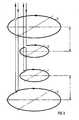
- Fig. 5 eine schematische Darstellung einer Kalibrierungsanordnung für ein Gradiometer zweiter Ordnung.
- 1 shows a first order gradiometer;
- 2 shows a second order gradiometer;
- 3 shows a first order gradiometer with associated calibration coils;
- 4 shows a schematic representation of a calibration arrangement for a first order gradiometer; and
- Fig. 5 is a schematic representation of a calibration arrangement for a second order gradiometer.
In Fig. 1 ist die Spulenanordnung eines axialen Gradiometers erster Ordnung schematisch dargestellt. Dieses besteht aus zwei in einem axialen Abstand voneinander angeordneten, elektrisch in Serie geschalteten Spulen mit parallelliegenden Spulenebenen. Die untere, dem zu messenden Magnetfeld zugeordnete Spule, ist die sogenannte Pickup-Spule 1, während die obere als Kompensationsspule 2 in der Weise mit der Pickup-Spule zusammenwirkt, daß homogene, von entfernten Quellen stammende Magnetfelder, die beide Spulen durchdringen, wegen der Gegensinnigkeit der Spulenwicklungen kompensiert werden. Beide Spulen sind über eine induktive Kopplung mit einem Superconducting Quantum Interference Device (Squid) verbunden und von einem Dewar-Gefäß umschlossen, welches durch Kühlung mit flüssigem Helium auf einer Temperatur von 4,2° K gehalten wird. Der Aufbau und die Funktion eines solchen Gradiometers ist in der Zeitschrift "Bild der Wissenschaft", Heft 8, 1986, Seiten 76-83 beschrieben und bedarf daher keiner näheren Erläuterung.In Fig. 1 the coil arrangement of an axial gradiometer of the first order is shown schematically. This consists of two coils arranged at an axial distance from each other, electrically connected in series with parallel coil levels. The lower coil, which is assigned to the magnetic field to be measured, is the so-called pickup coil 1, while the upper, as
Die in Fig. 2 dargestellte Spulenanordnung eines Gradiometers zweiter Ordnung besitzt zusätzlich zu den beiden genannten Spulen eine zwischen diesen angeordnete Zentralspule 3, deren zwei Windungen gleichsinnig gewickelt und elektrisch in Serie geschaltet sind. Der Wicklungssinn der beiden Wicklungen der Zentralspule 3 ist entgegengesetzt demjenigen der Pickup-Spule 1 und der Kompensationsspule 2. Dabei ist der Wicklungssinn der Kompensationsspule 2 demjenigen der Pickup-Spule 1 gleichgerichtet. Alle drei Spulen sind elektrisch in Serie geschaltet und über eine nicht dargestellte induktive Kopplung mit dem zugeordneten Squid verbunden. Die Art des Zusammenwirkens der drei Spulen eines solchen Gradiometers zweiter Ordnung ist in IEEE Transactions in Biomedical Engineering unter dem Titel "SQUID ARRAYS FOR SIMULTANEOUS MAGNETIC MEASUREMENTS: CALIBRATION AND SOURCE LOCALIZATION PERFORMANCE" von P. Costa Ribeiro, S.J. Williamson und L. Kaufman, Seite 3 unter A. "Large-Coil Calibration Technique" beschrieben und bedarf daher keiner näheren Erläuterung.The coil arrangement of a second-order gradiometer shown in FIG. 2 has, in addition to the two coils mentioned, a
Bei dem in dieser Arbeit ebenfalls beschriebenen Kalibrierungsverfahren wird eine Kalibrierungsspule in der Ebene der Pickup-Spule 1 angeordnet und erzeugt ein Magnetfeld, welches bei einem Gradiometer erster Ordnung sowohl die Pickup-Spule 1 wie die Kompensationsspule 2 in unterschiedlicher Stärke durchdringt. Die Größe der Feldstärke in der Ebene der Pickup-Spule und der Kompensationsspule wird zunächst numerisch berechnet. Dann wird die Differenz der beiden Felder gebildet und dieser Differenzwert durch die am Ausgang des Pickup-Verstärkers entstehende Meßspannung V dividiert. Der so erhaltene Wert ist der sogenannte Kalibrierungsfaktor k. Nun besitzt ein reales Gradiometer einen Fehlabgleich, der bewirkt, daß der von den beiden Spulen aufgrund der sie durchdringenden Felder erzeugte Strom von dem aufgrund des Gradientenfeldes tatsächlich erzeugten Strom abweicht. Der Grad der Abweichung läßt sich in einer Fehlerspannung Vf ausdrücken, die die Meßspannung V verfälscht. Bei genauer Kenntnis des Fehlabgleichfaktors f kann diese Fehlerspannung Vf berechnet und von der Meßspannung V subtrahiert werden. Eine genaue Messung des Fehlabgleichfaktors f ist jedoch deshalb sehr aufwendig, weil es dazu der Erzeugung eines sehr homogenen Kompensationsmagnetfeldes und für Gradiometer n-ter Ordnung zusätzlich exakter Feldgradienten bis (n-1)-ter Ordnung bedarf.In the calibration method also described in this work, a calibration coil is arranged in the plane of the pickup coil 1 and generates a magnetic field which, in the case of a first-order gradiometer, penetrates both the pickup coil 1 and the
Dieser Aufwand kann durch eine in Fig. 3 dargestellte Kalibrierungsspulenanordnung bei gleicher Genauigkeit erheblich vermindert werden. Zunächst ist davon auszugehen, daß die Fehlerspannung Vf von den homogenen Magnetfeldanteilen in den Spulenebenen hervorgerufen wird. Dieser homogene Anteil Bh ist die Summe der Magnetfelder in den Ebenen der beteiligten Spulen: Bh = B1 + B2, wobei B1 das Feld in der Ebene der Pick-up-Spule 1 und B2 das Feld in der Ebene der Kompensationsspule 2 bei einem Gradiometer erster Ordnung gemäß Fig. 1 ist. Wird nun dafür gesorgt, daß ein homogener Feldanteil nicht auftritt, d.h. Null ist, so geht ein Gradiometer-Fehlabgleich grundsätzlich nicht in die Kalibrierungsmessung ein. Dies läßt sich durch eine Anordnung gemäß Fig. 3 erreichen. Dort ist ein Gradiometer erster Ordnung mit der Pickup-Spule 1 und der Kompensationsspule 2 dargestellt. Dies entspricht einer Anordnung nach Fig. 1. Die Kalibrierungsspulen 4 und 5 sind achssymmetrisch und in gleichen Abständen 1 der parallelliegenden Spulenebenen angeordnet. Die Kalibrierungsspulen 4 und 5 sind elektrisch in Serie geschaltet und besitzen die gleichen Windungszahlen. Der Wicklungssinn der Kompensationsspulen 4 und 5 ist entgegengesetzt gerichtet.This effort can be significantly reduced by a calibration coil arrangement shown in FIG. 3 with the same accuracy. First of all, it can be assumed that the error voltage Vf is caused by the homogeneous magnetic field components in the coil planes. This homogeneous component Bh is the sum of the magnetic fields in the levels of the coils involved: Bh = B1 + B2, with B1 the field in the level of the pick-up coil 1 and B2 the field in the level of the
Diese Anordnung ist in Fig. 4 stark schematisiert dargestellt. Der durch die Kalibrierungsspulen 4 und 5 fließende Wechselstrom I erzeugt an der Pickup-Spule 1 des Gradiometers ein Feld B1 = B und an der Kompensationsspule 2 ein Feld B2 = -B. Demzufolge gilt für den homogenen Feldanteil Bh:
Bh = B1 + B2 = B - B = 0.
Gemessen wird dabei der erste Feldgradient Bg1:
Bg1 = B1 - B2 = B - (-B) = 2B.This arrangement is shown in a highly schematic manner in FIG. 4. The alternating current I flowing through the
Bh = B1 + B2 = B - B = 0.
The first field gradient Bg1 is measured:
Bg1 = B1 - B2 = B - (-B) = 2B.
Für die Kalibrierung wird der Feldgradient über den Gradiometerspulen berechnet und durch die gemessene Meßspannung V am Ausgang der SQUID-Elektronik dividiert.For the calibration, the field gradient is calculated via the gradiometer coils and divided by the measured voltage V at the output of the SQUID electronics.
In Fig. 5 sind die Verhältnisse an einem Gradiometer zweiter Ordnung gemäß Fig. 2 dargestellt. Dabei liegt in der Ebene der Zentralspule 3 eine weitere Kalibrierungsspule 6. Die Abstände zwischen der Pickup-Spule 1 und der Zentralspule 3 sowie zwischen dieser und der Kompensationsspule 2 sind mit 1₁ bezeichnet. Bei dieser Anordnung muß dafür gesorgt werden, daß sowohl das homogene Magnetfeld Bh über den Gradiometerspulen als auch der Gradient erster Ordnung Bg1 zu Null werden.
Bh = B1 + B2 + B3 = 0
Bg1 = (B1 - B3) + (B3 - B2) = B1 - B2 = 0
Am Gradiometer wird der Gradient zweiter Ordnung Bg2 gemessen:
Bg2 = (B1 - B3) - (B3 - B2) = B1 - 2 B3 + B25 shows the relationships on a second order gradiometer according to FIG. 2. There is a further calibration coil 6 in the plane of the
Bh = B1 + B2 + B3 = 0
Bg1 = (B1 - B3) + (B3 - B2) = B1 - B2 = 0
The second order gradient Bg2 is measured on the gradiometer:
Bg2 = (B1 - B3) - (B3 - B2) = B1 - 2 B3 + B2
Damit nun Bh = 0 und Bg1 = 0 werden, muß durch die Kalibrierungsspulen 4, 5, 6 folgende Feldverteilung am Gradiometer herrschen:
B1 = B; B3 = B und B2 = - 2 B;
daraus ergibt sich:
Bg2 = 6 B; Bg1 = 0 und Bh = 0.So that Bh = 0 and Bg1 = 0, the following field distribution on the gradiometer must prevail through the calibration coils 4, 5, 6:
B1 = B; B3 = B and B2 = - 2 B;
this results in:
Bg2 = 6 B; Bg1 = 0 and Bh = 0.
Diese Feldverteilung kann durch drei oder auch mehr symmetrisch in der Höhe um die Gradiometerspulen verteilt angeordnete Kalibrierungsspulen erzeugt werden. Dabei kommt es auf die Abstände der Kalibrierungsspulen zu den Gradiometerspulen und das Verhältnis der Windungszahlen zwischen den Kalibrierungsspulen an. Die Form der verwendeten Kalibrierungsspulen ist im Prinzip beliebig, solange das erzeugte Magnetfeld numerisch oder analytisch an den Orten der Gradiometerspulen berechnet werden kann.This field distribution can be generated by three or even more calibration coils arranged symmetrically in height around the gradiometer coils. It depends on the distances between the calibration coils and the gradiometer coils and the ratio of the number of turns between the calibration coils. In principle, the shape of the calibration coils used can be as long as the magnetic field generated can be calculated numerically or analytically at the locations of the gradiometer coils.
Das gezeigte Prinzip läßt sich auf Gradiometer beliebiger hoher Ordnung erweitern. Für Gradiometer n-ter Ordnung muß lediglich dafür gesorgt werden, daß die von den Kalibrierungsspulen erzeugten Feldverteilungen derart gewählt werden, daß die Feldgradienten bis zur (n-1)-ten Ordnung zu Null werden. Die hierfür benötigte Feldverteilung kann direkt aus der Formel für den Feldgradienten, den das jeweilige Gradiometer mißt, abgelesen werden. Um diese Magnetfeldverteilung zu erzeugen, sind mindestens (n + 1) Kalibrierungsspulen erforderlich, wobei n die Ordnung des Gradiometers ist.The principle shown can be extended to gradiometers of any high order. For n-order gradiometers, it is only necessary to ensure that the field distributions generated by the calibration coils are selected such that the field gradients become zero up to the (n-1) -th order. The field distribution required for this can be read directly from the formula for the field gradient that the respective gradiometer measures. To generate this magnetic field distribution, at least (n + 1) calibration coils are required, where n is the order of the gradiometer.
Der exakte Abstand der Kalibrierungsspulen zu den Gradiometerspulen und das Verhältnis der Windungszahlen zwischen den Kalibrierungsspulen, die benötigt werden, um eine bestimmte Feldverteilung zu erzeugen, läßt sich mit Hilfe einer Optimierungsrechnung ermitteln.The exact distance between the calibration coils and the gradiometer coils and the ratio of the number of turns between the calibration coils, which are required to generate a certain field distribution, can be determined using an optimization calculation.
Claims (3)
Translated fromGermandadurch gekennzeichnet, daß bei einem Gradiometer ersten Grades die den beiden Gradiometerspulen (1, 2) zugeordneten Kalibrierungsspulen (4, 5) um gleiche axiale Abstände gegenüber den zugeordneten Gradiometerspulen (1, 2) nach außen versetzt angeordnet sind.2. Arrangement for performing the method according to claim 1,
characterized in that in the case of a gradiometer of the first degree, the calibration coils (4, 5) assigned to the two gradiometer coils (1, 2) are arranged offset to the outside by the same axial distances from the assigned gradiometer coils (1, 2).
dadurch gekennzeichnet, daß bei einem Gradiometer zweiten Grades die den beiden äußeren Gradiometerspulen (1, 2) zugeordneten Kalibrierungsspulen (5, 6) um gleiche axiale Abstände gegenüber den zugeordneten Gradiometerspulen nach außen versetzt angeordnet sind und die Spulenebenen der mittleren Gradiometerspule (3) und der dieser zugeordneten Kalibrierungsspule (6) zusammenfallen.3. Arrangement for performing the method according to claim 1,
characterized in that, in the case of a second degree gradiometer, the calibration coils (5, 6) assigned to the two outer gradiometer coils (1, 2) are arranged offset by the same axial distances from the associated gradiometer coils and the coil planes of the middle gradiometer coil (3) and the this associated calibration coil (6) coincide.
Priority Applications (4)
| Application Number | Priority Date | Filing Date | Title |
|---|---|---|---|
| EP89105569AEP0390935A1 (en) | 1989-03-29 | 1989-03-29 | Calibration method for multichannel squid systems with gradiometers in any order |
| FI901324AFI901324A7 (en) | 1989-03-29 | 1990-03-16 | Method for calibrating multichannel SQUID systems comprising gradiometers of any order |
| JP2075354AJPH02281170A (en) | 1989-03-29 | 1990-03-23 | Method and equipment for correcting multichannel squid equipment |
| US07/498,617US4983912A (en) | 1989-03-29 | 1990-03-26 | Method for calibrating SQUID gradiometers of an arbitrary order |
Applications Claiming Priority (1)
| Application Number | Priority Date | Filing Date | Title |
|---|---|---|---|
| EP89105569AEP0390935A1 (en) | 1989-03-29 | 1989-03-29 | Calibration method for multichannel squid systems with gradiometers in any order |
Publications (1)
| Publication Number | Publication Date |
|---|---|
| EP0390935A1true EP0390935A1 (en) | 1990-10-10 |
Family
ID=8201147
Family Applications (1)
| Application Number | Title | Priority Date | Filing Date |
|---|---|---|---|
| EP89105569AWithdrawnEP0390935A1 (en) | 1989-03-29 | 1989-03-29 | Calibration method for multichannel squid systems with gradiometers in any order |
Country Status (4)
| Country | Link |
|---|---|
| US (1) | US4983912A (en) |
| EP (1) | EP0390935A1 (en) |
| JP (1) | JPH02281170A (en) |
| FI (1) | FI901324A7 (en) |
Cited By (1)
| Publication number | Priority date | Publication date | Assignee | Title |
|---|---|---|---|---|
| CN110297202A (en)* | 2019-07-19 | 2019-10-01 | 广东省计量科学研究院(华南国家计量测试中心) | The flexible current sensor verification system and method for the ampere-turns coil such as based superconductive |
Families Citing this family (27)
| Publication number | Priority date | Publication date | Assignee | Title |
|---|---|---|---|---|
| WO2002018959A2 (en)* | 2000-08-29 | 2002-03-07 | Cardiomag Imaging, Inc. | Calibrating squid channels |
| US6650107B2 (en) | 2001-08-23 | 2003-11-18 | Cariomag Imaging, Inc. | Calibrating SQUID channels |
| US7319331B2 (en)* | 2004-05-07 | 2008-01-15 | Baker Hughes Incorporated | Two loop calibrator |
| GB2425610A (en)* | 2005-04-29 | 2006-11-01 | Univ London | Magnetic properties sensing system |
| EP1843177A1 (en)* | 2006-04-06 | 2007-10-10 | Leica Geosystems AG | Calibration method and calibration apparatus for a hand-held locating device |
| US10634741B2 (en) | 2009-12-04 | 2020-04-28 | Endomagnetics Ltd. | Magnetic probe apparatus |
| US9427186B2 (en) | 2009-12-04 | 2016-08-30 | Endomagnetics Ltd. | Magnetic probe apparatus |
| EP2968560B1 (en) | 2013-03-11 | 2020-04-29 | Endomagnetics Ltd. | Hypoosmotic solutions for lymph node detection |
| US9239314B2 (en) | 2013-03-13 | 2016-01-19 | Endomagnetics Ltd. | Magnetic detector |
| WO2014140567A2 (en)* | 2013-03-13 | 2014-09-18 | Endomagnetics Ltd. | Magnetic detector |
| US9234877B2 (en) | 2013-03-13 | 2016-01-12 | Endomagnetics Ltd. | Magnetic detector |
| CN104569884B (en)* | 2013-10-18 | 2017-10-27 | 中国科学院上海微系统与信息技术研究所 | The caliberating device and method of a kind of SPUID three axis magnetometer |
| US9921331B2 (en) | 2014-12-17 | 2018-03-20 | Cgg Services Sas | Multi-sensor system for airborne geophysical prospecting and method |
| JP6821665B2 (en) | 2015-06-04 | 2021-01-27 | エンドマグネティクス リミテッド | Magnetic marker |
| JP6748287B2 (en)* | 2016-04-15 | 2020-08-26 | サウジ アラビアン オイル カンパニー | Magnetic induction-based localization for underground sensor reservoir wireless sensor networks |
| US11723579B2 (en) | 2017-09-19 | 2023-08-15 | Neuroenhancement Lab, LLC | Method and apparatus for neuroenhancement |
| US11717686B2 (en) | 2017-12-04 | 2023-08-08 | Neuroenhancement Lab, LLC | Method and apparatus for neuroenhancement to facilitate learning and performance |
| US11273283B2 (en) | 2017-12-31 | 2022-03-15 | Neuroenhancement Lab, LLC | Method and apparatus for neuroenhancement to enhance emotional response |
| US12280219B2 (en) | 2017-12-31 | 2025-04-22 | NeuroLight, Inc. | Method and apparatus for neuroenhancement to enhance emotional response |
| US11364361B2 (en) | 2018-04-20 | 2022-06-21 | Neuroenhancement Lab, LLC | System and method for inducing sleep by transplanting mental states |
| EP3849410A4 (en) | 2018-09-14 | 2022-11-02 | Neuroenhancement Lab, LLC | SLEEP ENHANCEMENT SYSTEM AND METHOD |
| US11786694B2 (en) | 2019-05-24 | 2023-10-17 | NeuroLight, Inc. | Device, method, and app for facilitating sleep |
| US11835675B2 (en) | 2019-08-07 | 2023-12-05 | Saudi Arabian Oil Company | Determination of geologic permeability correlative with magnetic permeability measured in-situ |
| US11879328B2 (en) | 2021-08-05 | 2024-01-23 | Saudi Arabian Oil Company | Semi-permanent downhole sensor tool |
| US11860077B2 (en) | 2021-12-14 | 2024-01-02 | Saudi Arabian Oil Company | Fluid flow sensor using driver and reference electromechanical resonators |
| US11867049B1 (en) | 2022-07-19 | 2024-01-09 | Saudi Arabian Oil Company | Downhole logging tool |
| US11913329B1 (en) | 2022-09-21 | 2024-02-27 | Saudi Arabian Oil Company | Untethered logging devices and related methods of logging a wellbore |
Citations (1)
| Publication number | Priority date | Publication date | Assignee | Title |
|---|---|---|---|---|
| GB2115552A (en)* | 1982-02-16 | 1983-09-07 | Emi Ltd | Improvements relating to magnetic field gradiometers |
Family Cites Families (5)
| Publication number | Priority date | Publication date | Assignee | Title |
|---|---|---|---|---|
| US4079730A (en)* | 1974-10-02 | 1978-03-21 | The Board Of Trustees Of The Leland Stanford Junior University | Apparatus for measuring externally of the human body magnetic susceptibility changes |
| US3980076A (en)* | 1974-10-02 | 1976-09-14 | The Board Of Trustees Of Leland Stanford Junior University | Method for measuring externally of the human body magnetic susceptibility changes |
| US4109199A (en)* | 1977-10-17 | 1978-08-22 | The United States Of America As Represented By The Secretary Of The Navy | Three axis magnetometer calibration checking method and apparatus |
| US4349781A (en)* | 1980-01-07 | 1982-09-14 | The Regents Of The University Of California | Superconducting gradiometer-magnetometer array for magnetotelluric logging |
| FR2564601B1 (en)* | 1984-05-15 | 1987-02-06 | Petroles Cie Francaise | MAGNETIC EXPLORATION APPARATUS FOR A BOREHOLE |
- 1989
- 1989-03-29EPEP89105569Apatent/EP0390935A1/ennot_activeWithdrawn
- 1990
- 1990-03-16FIFI901324Apatent/FI901324A7/ennot_activeIP Right Cessation
- 1990-03-23JPJP2075354Apatent/JPH02281170A/enactivePending
- 1990-03-26USUS07/498,617patent/US4983912A/ennot_activeExpired - Fee Related
Patent Citations (1)
| Publication number | Priority date | Publication date | Assignee | Title |
|---|---|---|---|---|
| GB2115552A (en)* | 1982-02-16 | 1983-09-07 | Emi Ltd | Improvements relating to magnetic field gradiometers |
Non-Patent Citations (3)
| Title |
|---|
| IEEE TRANSACTIONS ON BIOMEDICAL ENGINEERING, Band 35, No. 7, Juli 1988, Seiten 351-560, IEEE, New York, US; P.C. RIBEIRO et al.: "Squid arrays for simultaneous magnetic meausrements: Calibration and source localization performance"* |
| PATENT ABSTRACTS OF JAPAN, (P-384), 31. August 1985; & JP-A-60 073 474 (NIPPON HOSO KYOKAI) 30-09-1983* |
| REVIEW OF SCENTIFIC INSTRUMENTS, Band 53, Nr. 12, Dezember 1982, Seiten 1815-1845, American Institute of Physics, New York, US; G.L. ROMANI et al.: "Biomagnetic instrumentation"* |
Cited By (1)
| Publication number | Priority date | Publication date | Assignee | Title |
|---|---|---|---|---|
| CN110297202A (en)* | 2019-07-19 | 2019-10-01 | 广东省计量科学研究院(华南国家计量测试中心) | The flexible current sensor verification system and method for the ampere-turns coil such as based superconductive |
Also Published As
| Publication number | Publication date |
|---|---|
| JPH02281170A (en) | 1990-11-16 |
| FI901324A7 (en) | 1990-09-30 |
| US4983912A (en) | 1991-01-08 |
| FI901324A0 (en) | 1990-03-16 |
Similar Documents
| Publication | Publication Date | Title |
|---|---|---|
| EP0390935A1 (en) | Calibration method for multichannel squid systems with gradiometers in any order | |
| EP0061520B2 (en) | Transducer without magnetic core for contactless measurement of a current | |
| EP0111827B2 (en) | Multichannel apparatus measuring varying weak magnetic fields, and method of manufacturing the same | |
| DE69707536T2 (en) | Inductive linear position sensor device | |
| DE69919723T2 (en) | Inductive magnetic sensor with several closely coupled windings | |
| EP0313132A2 (en) | Device for multichannel measuring of weak magnetic fields | |
| DE4419730A1 (en) | RF probe for nuclear spin tomography | |
| EP0130490A1 (en) | Super-conductive gradiometer coil system for a device for the multichannel testing of weak, changing magnetic fields | |
| DE69217142T2 (en) | Nuclear magnetic resonance device with decoupled receiving coils | |
| CH651152A5 (en) | Messwandler for measuring an especially a measuring electricity generated magnetic field. | |
| EP0274767A1 (en) | Method and circuit for determining the pick-off position of a remotely controlled resistance transmitter | |
| EP0386824B1 (en) | Superconductive gradiometer for weak magnetic-field measurement, and method of producing same | |
| DE68928063T2 (en) | Position sensor with opposing coils for improved linearity and temperature compensation | |
| DE4425903A1 (en) | Device with a measuring transformer for detecting the position of a linearly movable object | |
| DE3228145A1 (en) | FINE BALANCE DEVICE FOR THREE-COIL GRADIOMETERS | |
| WO1998016839A1 (en) | Method and device for measuring current | |
| DE1448760B2 (en) | Use of a Hall plate to determine the deflection of an object with a magnetic field from a normal position | |
| DE2625354B2 (en) | Transmitter for direct and alternating current signals with a ferromagnetic core that allows at least two independent magnetic fluxes | |
| CH664218A5 (en) | METHOD AND ARRANGEMENT FOR AT LEAST PARTIAL ELIMINATION OF AN INTERFERENCE SIGNAL FROM A TOTAL SIGNAL. | |
| DE3828407A1 (en) | HIGH FREQUENCY COIL | |
| DE2646467C3 (en) | Superconducting coil arrangement for measurement purposes | |
| EP0029903B1 (en) | Measuring arrangement for electric currents | |
| DE3409448C2 (en) | ||
| DE2437887C2 (en) | ||
| DE3109212A1 (en) | GRADIENT KNIFE FOR MEASURING SPATIAL LEADS OF A MAGNETIC FIELD H |
Legal Events
| Date | Code | Title | Description |
|---|---|---|---|
| PUAI | Public reference made under article 153(3) epc to a published international application that has entered the european phase | Free format text:ORIGINAL CODE: 0009012 | |
| AK | Designated contracting states | Kind code of ref document:A1 Designated state(s):DE FR IT NL | |
| RBV | Designated contracting states (corrected) | Designated state(s):DE IT NL | |
| 17P | Request for examination filed | Effective date:19901026 | |
| 17Q | First examination report despatched | Effective date:19920717 | |
| STAA | Information on the status of an ep patent application or granted ep patent | Free format text:STATUS: THE APPLICATION IS DEEMED TO BE WITHDRAWN | |
| 18D | Application deemed to be withdrawn | Effective date:19921128 |