EP0389720B1 - Radar detection of targets at short and long range - Google Patents
Radar detection of targets at short and long rangeDownload PDFInfo
- Publication number
- EP0389720B1 EP0389720B1EP89313356AEP89313356AEP0389720B1EP 0389720 B1EP0389720 B1EP 0389720B1EP 89313356 AEP89313356 AEP 89313356AEP 89313356 AEP89313356 AEP 89313356AEP 0389720 B1EP0389720 B1EP 0389720B1
- Authority
- EP
- European Patent Office
- Prior art keywords
- output
- input
- mixer
- bandpass filter
- pulse
- Prior art date
- Legal status (The legal status is an assumption and is not a legal conclusion. Google has not performed a legal analysis and makes no representation as to the accuracy of the status listed.)
- Expired - Lifetime
Links
- 238000001514detection methodMethods0.000titledescription8
- 238000007906compressionMethods0.000claimsdescription63
- 230000006835compressionEffects0.000claimsdescription62
- 230000001131transforming effectEffects0.000claimsdescription3
- 230000005540biological transmissionEffects0.000description6
- 230000005855radiationEffects0.000description4
- 238000000034methodMethods0.000description3
- 238000005311autocorrelation functionMethods0.000description2
- 230000001427coherent effectEffects0.000description2
- 238000002955isolationMethods0.000description2
- 238000005070samplingMethods0.000description2
- 238000006243chemical reactionMethods0.000description1
- 239000002131composite materialSubstances0.000description1
- 238000010586diagramMethods0.000description1
- 230000000694effectsEffects0.000description1
- 239000000203mixtureSubstances0.000description1
- 238000012986modificationMethods0.000description1
- 230000004048modificationEffects0.000description1
- 230000000717retained effectEffects0.000description1
- 230000001629suppressionEffects0.000description1
- 230000001360synchronised effectEffects0.000description1
Images

Classifications
- G—PHYSICS
- G01—MEASURING; TESTING
- G01S—RADIO DIRECTION-FINDING; RADIO NAVIGATION; DETERMINING DISTANCE OR VELOCITY BY USE OF RADIO WAVES; LOCATING OR PRESENCE-DETECTING BY USE OF THE REFLECTION OR RERADIATION OF RADIO WAVES; ANALOGOUS ARRANGEMENTS USING OTHER WAVES
- G01S13/00—Systems using the reflection or reradiation of radio waves, e.g. radar systems; Analogous systems using reflection or reradiation of waves whose nature or wavelength is irrelevant or unspecified
- G01S13/02—Systems using reflection of radio waves, e.g. primary radar systems; Analogous systems
- G01S13/06—Systems determining position data of a target
- G01S13/08—Systems for measuring distance only
- G01S13/10—Systems for measuring distance only using transmission of interrupted, pulse modulated waves
- G01S13/26—Systems for measuring distance only using transmission of interrupted, pulse modulated waves wherein the transmitted pulses use a frequency- or phase-modulated carrier wave
- G01S13/28—Systems for measuring distance only using transmission of interrupted, pulse modulated waves wherein the transmitted pulses use a frequency- or phase-modulated carrier wave with time compression of received pulses
- G01S13/284—Systems for measuring distance only using transmission of interrupted, pulse modulated waves wherein the transmitted pulses use a frequency- or phase-modulated carrier wave with time compression of received pulses using coded pulses
- G—PHYSICS
- G01—MEASURING; TESTING
- G01S—RADIO DIRECTION-FINDING; RADIO NAVIGATION; DETERMINING DISTANCE OR VELOCITY BY USE OF RADIO WAVES; LOCATING OR PRESENCE-DETECTING BY USE OF THE REFLECTION OR RERADIATION OF RADIO WAVES; ANALOGOUS ARRANGEMENTS USING OTHER WAVES
- G01S13/00—Systems using the reflection or reradiation of radio waves, e.g. radar systems; Analogous systems using reflection or reradiation of waves whose nature or wavelength is irrelevant or unspecified
- G01S13/02—Systems using reflection of radio waves, e.g. primary radar systems; Analogous systems
- G01S13/06—Systems determining position data of a target
- G01S13/08—Systems for measuring distance only
- G01S13/10—Systems for measuring distance only using transmission of interrupted, pulse modulated waves
- G01S13/30—Systems for measuring distance only using transmission of interrupted, pulse modulated waves using more than one pulse per radar period
Definitions
- the inventionrelates to a pulse compression radar system. More specifically, the invention relates to such a system which includes a generator for generating for transmission, frequency or phase modulated pulses, each pulse consisting of two or more sub pulses each of which is modulated by a different pulse compression code for detecting targets at short range and long range, the compression codes having low cross-correlation properties, the sub pulses having the same centre frequency, one of the sub pulses being substantially longer than the other sub pulse.
- the two pulsesare separated in frequency (centre frequency of the modulated pulses) to ensure isolation and thus two separate channels and a combiner are required in the transmitter; and a splitter and two separate paths are required in the receiver.
- a second variation of this systemis described in U.S. Patent 4,524,361, Teulings, June 18, 1985, which modulates the short pulse for improved range resolution at the shorter ranges.
- the centre frequencies of the two modulated pulsesare still different to ensure isolation of one pulse from the other in the receiver channel.
- the ′746 patentteaches an apparatus for generating a modulation signal in the transmitter of a pulse compression system, and specifically, a chirp modulation signal.
- the ′926 patentrelates to improved expansion and compression devices for transmitter pulses and receiver pulses of pulse compression systems.
- the ′478 patentteaches an MTI pulse compression system wherein two side by side pulses of equal length (see Figure 2b of the patent) are transmitted.
- the first pulseis compression coded with an up chirp and the second pulse is compression coded with a down chirp.
- the system in the ′478 patentcan be used only for a single range.
- the compressed pulsesare substracted in the I.F. differencer (28 or Fig. 1 of the patent).
- the ′900 patentdiscloses two complimentary phase-coded signals which are synchronously transmitted in a pulse compression system such that, the two autocorrelation functions, when combined, are mutually cancelling except at the synchronous occurrence of the maxima of the autocorrelation functions.
- a doppler tolerant pulse compression systemis described in the ′562 patent.
- An analogtype linear FM modulated transmission pulseis used, and its echo is processed by baseband sampling at the Nyquist sampling rate and then converted to IF.
- the ′720 patentrelates to a radar system where long and short pulses are alternately transmitted. However, this system does not use pulse compression techniques.
- the ′779 patentrelates to a decoder for a pulse compression system.
- Both the ′362 and ′863 patentsteach pulse compression systems using a fast Fourier transform circuit in a matched filter.
- a system for generating continuous waves useful in pulse compression systemsis described.
- a processor for a pulse compression signal useful in a pulse compression systemis described. The object of the processor is to enhance the resolvability of the returns.
- the primary objective of the inventionis to provide a radar pulse compression system which has good target detection at both long range and relatively short range using minimal hardware for savings in cost and complexity.
- This objectiveis met by generating, transmitting, receiving and compressing two or more frequency or phase coded pulses at the same centre frequency as one another.
- the pulsesare coded with pulse compression waveforms; however, one pulse is substantially longer than the other.
- the longer pulsecontains more energy for detection of targets at long range.
- the shorter pulseis coded for optimal target detection at shorter ranges.
- the pulse compression codesare designed with low cross correlation properties so that the matched filter or compressor corresponding to each code decorrelates or rejects the other.
- These two or more pulsesmay be generated contiguously in time so that they form one long pulse comprised of the two or more sub pulses or they may be transmitted separately in any sequence, as dictated by the radar system requirements. It is expected that the most commonly used method will be to transmit two sub pulses in immediate succession, the first one being the longer pulse used for long range detection followed by the shorter pulse for close in target detection. This configuration is used when a general search of all ranges is required since the short sub pulse is received as soon as possible after it is transmitted, covering as short a range as possible.
- a pulse compression radar systemcomprising: a transmitting channel including means for generating frequency or phase code modulated pulses having a centre frequency, and means for transforming said pulses to a desired transmitting frequency; means for radiating said transformed frequency pulses and for receiving return signals; and a receiver for processing said return signals, said receiver including a pulse compressor means for compressing said return signals; each said pulse to be transmitted comprising two or more sub pulses (T L , T S ) of substantially different lengths, each sub pulse being coded with a different compression code, the compression of each sub pulse code having a low cross-correlation property with the compression codes of all other sub pulses, all said sub pulses having the same centre frequency; and characterised in that the receiver comprises a single channel including said pulse compressor means through which all return signals pass serially, the pulse compression means compressing said return pulses by means of a plurality of sets of coefficients each of which sets correlates with a respective different one of said sub pulses and decorrelates with the others.
- the pulse compression systemcomprises a pulse generator unit 1, a timing and control unit 2 and pulse compressor means 3.
- the pulse generatorgenerates two sub pulses, which, as above mentioned, can be contiguous to one another.
- Each of the sub pulsesis frequency or phase modulated about a centre frequency, and each sub pulse is coded with a different compression code, the different compression code of each pulse having a low cross-correlation property to the compression codes of every other sub pulses. All sub pulses have the same centre frequency.
- the pulsesare transmitted to the antenna for radiation.
- the generated transmit pulsesare coherent with the clock system which is accomplished by timing signals provided by the timing and control unit 2.
- the transmit pulseis produced in the pulse generator unit, either by generating the in-phase and quadrature components of the complex waveform at baseband and modulating with an IF carrier, or by generating directly at IF. Techniques for accomplishing waveform generation of this type are well known in the prior art relating to radar systems.
- the pulse compression codes of each of the sub pulsesare designed such that the compression code for each sub pulse decorrelates or suppresses the other codes.
- the pulse compression means 3may contain a single pulse compressor unit with two or more sets of coefficients, wherein one set of coefficients will correlate with the compression code of one of the pulses and will decorrelate with the compression codes of the other sub pulses, and other sets of coefficients will correlate with the compression codes of the other sub pulses and will decorrelate with the compression code of the one sub pulse.
- a switch meansillustrated schematically at 6, will switch in one set of coefficients at a time. The first set of coefficients will be switched in at the time that a pulse is transmitted and will stay switched in for a time equal to the maximum range of the short range pulse. The second set of coefficients will then be switched in until the next pulse is transmitted.
- one of the pulse compressor unitswill have coefficients which correlate with the compression code of one of the sub pulses but which decorrelate with the other ones of the sub pulses.
- Another pulse compressor unitwill have coefficients which correlate with another one of the sub pulses but decorrelate with the remainder of the sub pulses, etc.
- there are two compressor unitsindicating two sub pulses.
- One or the other pulse compressor unitswill be switched into circuit by a switch illustrated schemetically at 6A. Alternatively, both compressor units can be switched on at all times.
- Figure 2Aillustrates the composition of a transmitted pulse when each pulse consists of only two sub pulses. This transmitted pulse will also appear at the input of the pulse compressor means 3. As seen in Figure 2A, the pulse consists of a long pulse T l and a short pulse T s . The two pulses, as shown in the Figure 2A, are contiguous. However, they may be spaced from each other. In either case, the short pulse will follow the long pulse.
- the Ratio T l /T smay vary from 2/1 to 100/1 but is typically 10/1. Typically T l will be 100 microseconds long and T s will be 10 microseconds long.
- the outputcontains the compressed pulse corresponding to the correlation of the long sub pulse with the long sub pulse coefficients, and the interference introduced by the presence of the shorter sub pulse. This interference is suppressed relative to the compressed pulse by the compression gain, G l plus the short sub pulse rejection, R ls .
- the output of the compressor having the coefficients of the shorter sub pulseshown in Figure 2C, contains the compressed pulse corresponding to the correlation to the short sub pulse with the short sub pulse coefficients as well as interference introduced by the longer sub pulse which is suppressed relative to the compressed sub pulse by G s plus R sl .
- a well known example of two mutually exclusive compression codeswhich can be used in the system of the present invention, is a linear FM coding where an up chirp is used for one sub pulse and a down chirp is used for the other sub pulse.
- the compression coefficients in the pulse compressor for each sub pulsemay or may not have weighting by a window for range side lobe suppression, standard practice in linear FM pulse compression design.
- the inventionis herein illustrated with a two sub pulse generator, it is conceivable that more than two sub pulses would be desirable. For example, if a third, longer range were to be added, a third sub pulse would be used.
- the third sub pulsewould be substantially longer than the first sub pulse (T l ) and would precede T l . It would have the same centre frequency as the first two sub pulses and its compression code would have low cross-correlation properties with the compression codes of the first and second sub pulses.
- FIG. 3A preferred embodiment of the invention is illustrated in Figure 3.
- the preferred embodimentincludes the pulse generator unit 1, the system timing and control unit 2 and the pulse compressor unit 3.
- Figure 3also illustrates a stable oscillator 7 for driving the system timing and control unit.
- Pulse generator unit 1is in the transmit channel which includes the pulse generator unit 1 as well as means for transforming the frequency of the generated pulses to a desired transmitting frequency.
- Such meansinclude a first mixer 8, having one input fed from the pulse generator unit 1 and a second input fed from a first local oscillator 9.
- the output of the first mixer 8is fed to a bandpass filter 10 which passes only the desired product of the mixer 8 output.
- the output of the first bandpass filter 10is connected to a second mixer 11 whose second output is fed from a second local oscillator 12.
- the output of the second mixer 11is fed to a second bandpass filter 13 which, once again, passes only the desired products of the second mixer 11.
- the ouput of the bandpass filter 13is fed through an R.F. amplifier 14.
- the output of the transmit channelis fed to an antenna unit 300 which includes antenna 15 and circulator or duplexer 16.
- the output of amplifier 14is fed to the circulator for transmission to the antenna for radiation through space.
- the circulator or duplexer 16will pass signals from the transmit channel to the antenna 15 for such radiation, and will pass signals from the antenna 15 to the receive channel 200 for processing.
- the circulator or duplexer 16is connected to a low noise amplifier 17 whose output is connected to a third bandpass filter 18 to remove any undesired out of band effects.
- the output of the third bandpass filter 18is fed to a third mixer 19 whose other output may be fed from the second local oscillator 12, or from a local oscillator at a different frequency as dictated by the requirements of further processing elements in the receiver channel 200.
- the output of the third mixer 19is fed to a fourth bandpass filter 20 to eliminate any undesired out of band frequencies.
- the output of the fourth bandpass filter 20is fed to a fourth mixer 21 whose second input is fed from the first local oscillator 9.
- a local oscillator of a different frequencycould be used.
- the output of the fourth mixer 21is fed to a fifth bandpass filter 22 whose output is fed to an analogue-to-digital converter and demodulator 23.
- the output of 23is fed to pulse compressor unit 3 where it is processed as discussed with respect to Figure 2 above.
- the output of the receive channel 200is then fed to further processing elements of the radar for further signal processing as required.
- the timing and control unitprovides the timing signals to the pulse generator unit 1, so that the pulses can be transmitted at the desired pulse repetition frequencies (PRFs) and may be maintained coherent with the system clock.
- the pulse compressor unit 3also receives signals from the timing and control unit 2 to co-ordinate the timing of the compression process with the rest of the system as above described.
- the timing and control unit 2may comprise several separate units in any particular radar system, each responsible for the control of a different area of the radar. Only the functions required to control the pulse compression system are described here.
- the transmit pulsesoriginate in the timing and control unit 1.
- the pulsesmay be produced either by generating the component in-phase and quadrature signals at baseband and then modulating the carrier signal, or the modulated IF carrier may be generated directly.
- the output of the pulse generator unit 1is a carrier signal modulated by the pulse compression code of the long and/or the short sub pulses as appropriate.
- the modulated signalis then mixed to the final transmit frequency by two mixer stages 8 and 11.
- the carrier frequency at the output of each mixeris determined by the centre frequency of the input signal and the frequencies of the local oscillators 9 and 12 respectively.
- Each mixeris followed by a bandpass filter stage 10 and 13 respectively which suppress all but the desired mixer sidebands for transmission.
- the signalis then amplified and transmitted through the antenna unit 300.
- the antenna unit 300may comprise both a transmitting and a receiving antenna or may comprise one antenna with a circulator or duplexer 16 or some other suitable duplexing system.
- a single antenna 15 with a circulator or duplexer 16 to separate and isolate the transmit and receive signalsis shown in Figure 3.
- the pulse compressionis performed digitally.
- a digital pulse compressorwill normally require separate in-phase and quadrature digital inputs.
- a different assumptionwill dictate a different A/D, demodulator combination.
- the A/D conversionmay be done before the demodulation in which case the centre frequency of the signal at the mixer output will be dictated by the speed of the A/D converter.
- a pulse generated by the pulse generator unit 1is transformed to the desired radiation frequency and radiated by the antenna.
- Returned signalswill be processed in the receive channel 200 which, during the period of the short range, will include either a pulse compressor, (in the case of two compressors), or a pulse compressor (in the case of a single pulse compressor unit), which has in use the coefficients which correlate with the compression on the short range sub pulse.
- the pulse compressor unit 3will have either a pulse compressor (in the case of two pulse compressors), or a pulse compressor (in the case of a single pulse compressor) which has in use the coefficients which correlate with the compression code of a long range sub pulse.
Landscapes
- Engineering & Computer Science (AREA)
- Radar, Positioning & Navigation (AREA)
- Remote Sensing (AREA)
- Computer Networks & Wireless Communication (AREA)
- Physics & Mathematics (AREA)
- General Physics & Mathematics (AREA)
- Radar Systems Or Details Thereof (AREA)
Description
- The invention relates to a pulse compression radar system. More specifically, the invention relates to such a system which includes a generator for generating for transmission, frequency or phase modulated pulses, each pulse consisting of two or more sub pulses each of which is modulated by a different pulse compression code for detecting targets at short range and long range, the compression codes having low cross-correlation properties, the sub pulses having the same centre frequency, one of the sub pulses being substantially longer than the other sub pulse.
- Traditionally, because of limited peak transmission power, pulse compression systems with relatively high compression ratios, and therefore long frequency or phase modulated pulses, have been used for long range detection in radar systems. The pulse compression code allows the range resolution performance of a short pulse to be retained; however, these systems are limited in their ability to detect targets at short ranges since the radar is usually unable to receive the reflected pulse until- transmission has ceased. To overcome this limitation, a system described in U.S. Patent 4,136,341, Mulder et al, January 23, 1979, was introduced in which a second pulse is generated and the two different pulses are transmitted. While the first pulse is phase or frequency modulated, the second pulse is not modulated and its length is optimized to ensure adequate detection at ranges not covered by the long modulated pulse. The two pulses are separated in frequency (centre frequency of the modulated pulses) to ensure isolation and thus two separate channels and a combiner are required in the transmitter; and a splitter and two separate paths are required in the receiver. A second variation of this system is described in U.S. Patent 4,524,361, Teulings, June 18, 1985, which modulates the short pulse for improved range resolution at the shorter ranges. The centre frequencies of the two modulated pulses are still different to ensure isolation of one pulse from the other in the receiver channel.
- The prior art has further teachings relating to pulse compression systems as, for example, in U.S. Patent Nos. 3,852,746, Lowenschuss et al, December 3, 1974; 3,860,926, Gillmer, January 14, 1975; 4,096,478, Chavez, June 20, 1978; 4,153,900, Novak et al, May 8, 1979; 4,404,562, Kretschmer, Jr. et al, September 13, 1983; 4,490,720, Kuntman, December 25, 1984; 4,521,779, Lewis, June 4, 1985; 4,524,362, Lewis, June 18, 1985; 4,524,363, Kretschmer, June 18, 1985; 4,560,961, Kestenbaum, December 24, 1985; 4,626,853, Lee et al, December 2, 1986.
- The ′746 patent teaches an apparatus for generating a modulation signal in the transmitter of a pulse compression system, and specifically, a chirp modulation signal. The ′926 patent relates to improved expansion and compression devices for transmitter pulses and receiver pulses of pulse compression systems.
- The ′478 patent teaches an MTI pulse compression system wherein two side by side pulses of equal length (see Figure 2b of the patent) are transmitted. The first pulse is compression coded with an up chirp and the second pulse is compression coded with a down chirp. However, because the pulses are of equal length, the system in the ′478 patent can be used only for a single range. In addition, the compressed pulses are substracted in the I.F. differencer (28 or Fig. 1 of the patent).
- The ′900 patent discloses two complimentary phase-coded signals which are synchronously transmitted in a pulse compression system such that, the two autocorrelation functions, when combined, are mutually cancelling except at the synchronous occurrence of the maxima of the autocorrelation functions. A doppler tolerant pulse compression system is described in the ′562 patent. An analogtype linear FM modulated transmission pulse is used, and its echo is processed by baseband sampling at the Nyquist sampling rate and then converted to IF.
- The ′720 patent relates to a radar system where long and short pulses are alternately transmitted. However, this system does not use pulse compression techniques.
- The ′779 patent relates to a decoder for a pulse compression system. Both the ′362 and ′863 patents teach pulse compression systems using a fast Fourier transform circuit in a matched filter. In the ′961 patent, a system for generating continuous waves useful in pulse compression systems is described. In the ′853 patent, a processor for a pulse compression signal useful in a pulse compression system is described. The object of the processor is to enhance the resolvability of the returns.
- The primary objective of the invention is to provide a radar pulse compression system which has good target detection at both long range and relatively short range using minimal hardware for savings in cost and complexity.
- This objective is met by generating, transmitting, receiving and compressing two or more frequency or phase coded pulses at the same centre frequency as one another. The pulses are coded with pulse compression waveforms; however, one pulse is substantially longer than the other. The longer pulse contains more energy for detection of targets at long range. The shorter pulse is coded for optimal target detection at shorter ranges. The pulse compression codes are designed with low cross correlation properties so that the matched filter or compressor corresponding to each code decorrelates or rejects the other.
- These two or more pulses may be generated contiguously in time so that they form one long pulse comprised of the two or more sub pulses or they may be transmitted separately in any sequence, as dictated by the radar system requirements. It is expected that the most commonly used method will be to transmit two sub pulses in immediate succession, the first one being the longer pulse used for long range detection followed by the shorter pulse for close in target detection. This configuration is used when a general search of all ranges is required since the short sub pulse is received as soon as possible after it is transmitted, covering as short a range as possible.
- In accordance with the invention there is provided a pulse compression radar system, comprising:
a transmitting channel including means for generating frequency or phase code modulated pulses having a centre frequency, and means for transforming said pulses to a desired transmitting frequency;
means for radiating said transformed frequency pulses and for receiving return signals; and
a receiver for processing said return signals, said receiver including a pulse compressor means for compressing said return signals;
each said pulse to be transmitted comprising two or more sub pulses (TL, TS) of substantially different lengths, each sub pulse being coded with a different compression code, the compression of each sub pulse code having a low cross-correlation property with the compression codes of all other sub pulses, all said sub pulses having the same centre frequency;
and characterised in that the receiver comprises a single channel including said pulse compressor means through which all return signals pass serially, the pulse compression means compressing said return pulses by means of a plurality of sets of coefficients each of which sets correlates with a respective different one of said sub pulses and decorrelates with the others. - The invention will be better understood by an examination of the following description, together with the accompanying drawings, in which:
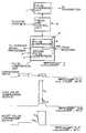
- FIGURE 1 illustrates a pulse compression system in block diagram form in accordance with the invention;
- FIGURES 2A, 2B and 2C illustrate the relationships between the waveforms at the inputs and outputs of the Pulse Compression Unit; and
- FIGURE 3 illustrates, in schematic form, a pulse compression radar system using the inventive pulse compression system.
- Referring to Figure 1, the pulse compression system comprises a pulse generator unit 1, a timing and
control unit 2 and pulse compressor means 3. The pulse generator generates two sub pulses, which, as above mentioned, can be contiguous to one another. Each of the sub pulses is frequency or phase modulated about a centre frequency, and each sub pulse is coded with a different compression code, the different compression code of each pulse having a low cross-correlation property to the compression codes of every other sub pulses. All sub pulses have the same centre frequency. - The pulses, as will be seen below, are transmitted to the antenna for radiation.
- The generated transmit pulses are coherent with the clock system which is accomplished by timing signals provided by the timing and
control unit 2. The transmit pulse is produced in the pulse generator unit, either by generating the in-phase and quadrature components of the complex waveform at baseband and modulating with an IF carrier, or by generating directly at IF. Techniques for accomplishing waveform generation of this type are well known in the prior art relating to radar systems. - The pulse compression codes of each of the sub pulses are designed such that the compression code for each sub pulse decorrelates or suppresses the other codes. The pulse compression means 3 may contain a single pulse compressor unit with two or more sets of coefficients, wherein one set of coefficients will correlate with the compression code of one of the pulses and will decorrelate with the compression codes of the other sub pulses, and other sets of coefficients will correlate with the compression codes of the other sub pulses and will decorrelate with the compression code of the one sub pulse. A switch means, illustrated schematically at 6, will switch in one set of coefficients at a time. The first set of coefficients will be switched in at the time that a pulse is transmitted and will stay switched in for a time equal to the maximum range of the short range pulse. The second set of coefficients will then be switched in until the next pulse is transmitted.
- If two or more pulse compressor units are used, then one of the pulse compressor units will have coefficients which correlate with the compression code of one of the sub pulses but which decorrelate with the other ones of the sub pulses. Another pulse compressor unit will have coefficients which correlate with another one of the sub pulses but decorrelate with the remainder of the sub pulses, etc. In the illustrated embodiment, there are two compressor units indicating two sub pulses. One or the other pulse compressor units will be switched into circuit by a switch illustrated schemetically at 6A. Alternatively, both compressor units can be switched on at all times.
- Figure 2A illustrates the composition of a transmitted pulse when each pulse consists of only two sub pulses. This transmitted pulse will also appear at the input of the pulse compressor means 3. As seen in Figure 2A, the pulse consists of a long pulse Tl and a short pulse Ts. The two pulses, as shown in the Figure 2A, are contiguous. However, they may be spaced from each other. In either case, the short pulse will follow the long pulse.
- The Ratio Tl/Ts may vary from 2/1 to 100/1 but is typically 10/1. Typically Tl will be 100 microseconds long and Ts will be 10 microseconds long.
- When the composite pulse, shown in Figure 2A, is processed by a pulse compressor having the coefficients of the longer sub pulse, the output, as shown in Figure 2B, contains the compressed pulse corresponding to the correlation of the long sub pulse with the long sub pulse coefficients, and the interference introduced by the presence of the shorter sub pulse. This interference is suppressed relative to the compressed pulse by the compression gain, Gl plus the short sub pulse rejection, Rls. Similarly, the output of the compressor having the coefficients of the shorter sub pulse, shown in Figure 2C, contains the compressed pulse corresponding to the correlation to the short sub pulse with the short sub pulse coefficients as well as interference introduced by the longer sub pulse which is suppressed relative to the compressed sub pulse by Gs plus Rsl.
- A well known example of two mutually exclusive compression codes, which can be used in the system of the present invention, is a linear FM coding where an up chirp is used for one sub pulse and a down chirp is used for the other sub pulse. The compression coefficients in the pulse compressor for each sub pulse may or may not have weighting by a window for range side lobe suppression, standard practice in linear FM pulse compression design.
- Although the invention is herein illustrated with a two sub pulse generator, it is conceivable that more than two sub pulses would be desirable. For example, if a third, longer range were to be added, a third sub pulse would be used. The third sub pulse would be substantially longer than the first sub pulse (Tl) and would precede Tl. It would have the same centre frequency as the first two sub pulses and its compression code would have low cross-correlation properties with the compression codes of the first and second sub pulses.
- A preferred embodiment of the invention is illustrated in Figure 3. Turning to Figure 3, it can be seen that the preferred embodiment includes the pulse generator unit 1, the system timing and
control unit 2 and thepulse compressor unit 3. - Figure 3 also illustrates a
stable oscillator 7 for driving the system timing and control unit. - Pulse generator unit 1 is in the transmit channel which includes the pulse generator unit 1 as well as means for transforming the frequency of the generated pulses to a desired transmitting frequency. Such means include a
first mixer 8, having one input fed from the pulse generator unit 1 and a second input fed from a first local oscillator 9. The output of thefirst mixer 8 is fed to abandpass filter 10 which passes only the desired product of themixer 8 output. The output of thefirst bandpass filter 10 is connected to a second mixer 11 whose second output is fed from a secondlocal oscillator 12. The output of the second mixer 11 is fed to asecond bandpass filter 13 which, once again, passes only the desired products of the second mixer 11. The ouput of thebandpass filter 13 is fed through an R.F.amplifier 14. - The output of the transmit channel is fed to an
antenna unit 300 which includesantenna 15 and circulator orduplexer 16. The output ofamplifier 14 is fed to the circulator for transmission to the antenna for radiation through space. As is well known, the circulator orduplexer 16 will pass signals from the transmit channel to theantenna 15 for such radiation, and will pass signals from theantenna 15 to the receivechannel 200 for processing. - For the latter purpose, the circulator or
duplexer 16 is connected to alow noise amplifier 17 whose output is connected to athird bandpass filter 18 to remove any undesired out of band effects. The output of thethird bandpass filter 18 is fed to athird mixer 19 whose other output may be fed from the secondlocal oscillator 12, or from a local oscillator at a different frequency as dictated by the requirements of further processing elements in thereceiver channel 200. The output of thethird mixer 19 is fed to afourth bandpass filter 20 to eliminate any undesired out of band frequencies. The output of thefourth bandpass filter 20 is fed to afourth mixer 21 whose second input is fed from the first local oscillator 9. Once again, a local oscillator of a different frequency could be used. - The output of the
fourth mixer 21 is fed to afifth bandpass filter 22 whose output is fed to an analogue-to-digital converter anddemodulator 23. The output of 23 is fed topulse compressor unit 3 where it is processed as discussed with respect to Figure 2 above. The output of the receivechannel 200 is then fed to further processing elements of the radar for further signal processing as required. - The timing and control unit,
item 2, provides the timing signals to the pulse generator unit 1, so that the pulses can be transmitted at the desired pulse repetition frequencies (PRFs) and may be maintained coherent with the system clock. Thepulse compressor unit 3, also receives signals from the timing andcontrol unit 2 to co-ordinate the timing of the compression process with the rest of the system as above described. The timing andcontrol unit 2 may comprise several separate units in any particular radar system, each responsible for the control of a different area of the radar. Only the functions required to control the pulse compression system are described here. - The transmit pulses originate in the timing and control unit 1. The pulses may be produced either by generating the component in-phase and quadrature signals at baseband and then modulating the carrier signal, or the modulated IF carrier may be generated directly. In either case, the output of the pulse generator unit 1 is a carrier signal modulated by the pulse compression code of the long and/or the short sub pulses as appropriate. The modulated signal is then mixed to the final transmit frequency by two
mixer stages 8 and 11. The carrier frequency at the output of each mixer is determined by the centre frequency of the input signal and the frequencies of thelocal oscillators 9 and 12 respectively. Each mixer is followed by abandpass filter stage antenna unit 300. Theantenna unit 300 may comprise both a transmitting and a receiving antenna or may comprise one antenna with a circulator orduplexer 16 or some other suitable duplexing system. Asingle antenna 15 with a circulator orduplexer 16 to separate and isolate the transmit and receive signals is shown in Figure 3. - In the described embodiments the pulse compression is performed digitally. A digital pulse compressor will normally require separate in-phase and quadrature digital inputs. A different assumption will dictate a different A/D, demodulator combination. The A/D conversion may be done before the demodulation in which case the centre frequency of the signal at the mixer output will be dictated by the speed of the A/D converter.
- In operation, a pulse generated by the pulse generator unit 1 is transformed to the desired radiation frequency and radiated by the antenna. Returned signals will be processed in the receive
channel 200 which, during the period of the short range, will include either a pulse compressor, (in the case of two compressors), or a pulse compressor (in the case of a single pulse compressor unit), which has in use the coefficients which correlate with the compression on the short range sub pulse. Following the short range period and until the end of a long range period, thepulse compressor unit 3 will have either a pulse compressor (in the case of two pulse compressors), or a pulse compressor (in the case of a single pulse compressor) which has in use the coefficients which correlate with the compression code of a long range sub pulse. - Although a single embodiment has been described, this was for the purpose of illustrating, but not limiting, the invention. Various modifications, which will come readily to the mind of one skilled in the art, are within the scope of the invention as defined in the appended claims.
Claims (10)
- A pulse compression radar system, comprising:
a transmitting channel (100) including means (1) for generating frequency or phase code modulated pulses having a centre frequency, and means (8 to 14) for transforming said pulses to a desired transmitting frequency;
means (15,16) for radiating said transformed frequency pulses and for receiving return signals; and
a receiver (200) for processing said return signals, said receiver including a pulse compressor means (3) for compressing said return signals;
each said pulse to be transmitted comprising two or more sub pulses (TL, TS) of substantially different lengths, each sub pulse being coded with a different compression code, the compression of each sub pulse code having a low cross-correlation property with the compression codes of all other sub pulses, all said sub pulses having the same centre frequency;
and characterised in that the receiver comprises a single channel (200) including said pulse compressor means (3) through which all return signals pass serially, the pulse compression means (3) compressing said return pulses by means of a plurality of sets of coefficients each of which sets correlates with a respective different one of said sub pulses and decorrelates with the others. - A system as defined in Claim 1, characterised in that each pulse comprises two sub pulses.
- A system as defined in Claim 2, characterised in that said transmit channel has at least one mixer (8,11), one bandpass filter (10,13) and one local oscillator (9,12).
- A system as defined in Claim 3, characterised in that said receiver channel has at least one mixer (19,21), one local oscillator (12,9) and one bandpass filter (18,20) having a passband sufficient to pass all of said sub pulses.
- A system as defined in any preceding claim, characterised in that said pulse compression means comprises two pulse compressor units (3), one of said pulse compressor units having coefficients which correlate with one of said sub pulses and which decorrelate with the other one of said sub pulses, the other one of said pulse compressor units having coefficients which correlate with the other one of said sub pulses and which decorrelate with the one of said sub pulses.
- A system as defined in Claim 5 and further including a second timing and control unit (2).
- A system as defined in Claim 6, characterised in that said means for generating frequency or phase code modulated pulses comprises a pulse generator unit (1) having an output and a control input;A) and in that said transmitting channel (100) comprises:
a first mixer (8) having a first input, a second input and an output, and means connecting said output of said pulse generator unit to said first input of said first mixer;
a first local oscillator (9) having a first output and a second output and a control input, means connecting said first output of said first local oscillator to said second input of said first mixer;
a first bandpass filter (10) having an input and an output, means connecting said output of said first mixer to said input of said bandpass filter;
a second mixer (11) having a first input a second input and an output, means connecting said output of said first bandpass filter to said first input of said second mixer;
a second local oscillator (12) having a first output and a second output, means connecting said first output of said second local oscillator to said second input of said second mixer;
a second bandpass filter (13) having an input and an output, means connecting said output of said second mixer to said input of said second bandpass filter;B) and in that antenna means (15,16) comprises:
a duplexer means (16) having a first input, a second input, a first output and a second output, means connecting said output of said second bandpass filter to said first input of said duplexer means; and
an antenna (15) having a first input and a first output, means connecting said first output of said duplexer means to said input of said antenna, means connecting said output of said antenna to said second input of said duplexer means;C) and in that said receiver channel means (200) comprises:
a low noise amplifier (17) having an input and an output, means connecting said second output of said duplexer means to said input of said low noise amplifier;
a third bandpass filter (18) having an input and an output, means connecting said input of said third bandpass filter to said output of said low noise amplifier;
a third mixer (19) having a first input, a second input and an output, means connecting said output of said third bandpass filter to said first input of said third mixer, means connecting said second output of said second local oscillator to said second input of said third mixer;
a fourth bandpass filter (20) having an input and an output, means connecting said output of said third mixer to said input of said fourth bandpass filter;
a fourth mixer (21) having a first input, a second input and an output, means connecting said output of said fourth bandpass filter to said first input of said fourth mixer, means connecting said second output of said first local oscillator to said second input of said fourth mixer;
a fifth bandpass filter (22) having an input and an output, means connecting said output of said fourth mixer to said input of said fifth bandpass filter;
analogue-to-digital converter and demodulator means (23) having an input and an output, means connecting said output of said fifth bandpass filter to said input of said analogue-to-digital converter and demodulator means;
a pulse compressor unit (3) having an input and a control input, means connecting said output of said analogue-to-digital converter and demodulator means to said input of said pulse compressor unit;D) and in that said system timing and control unit (2) comprises:
a system timer and controller having a first output, a second output and a third output, said first output of said system timer and controller being connected to the control input of said pulse generator unit (1), said second output of said system timer and controller being connected to the control input of said first local oscillator (9), and said third output of said system timer and controller being connected to the control input of said pulse compressor unit (3). - The system as defined in any of Claims 1 to 4, characterised in that said pulse compressor unit comprises a single pulse compressor having a first set of coefficients which correlates with one of said sub pulses and decorrelates with the other one of said sub pulses, and a second set of coefficients which correlates with the other one of said sub pulses and decorrelates with the one of said sub pulses;
means for switching said sets of coefficients into circuit one at a time. - A system as defined in Claim 8, and further including a system timing and control unit (2).
- A system as defined in Claim 9, characterised in that said means for generating frequency or phase code modulated pulses comprises a pulse generator unit (1) having an ouptut and a control input;A) and in that said transmitting channel (100) further comprises:
a first mixer (8) having a first input, a second input and an output, and means connecting said output of said pulse generator unit to said first input of said first mixer;
a first local oscillator (9) having a first output a second output and a control input, means connecting said first output of said first local oscillator to said second input of said first mixer;
a first bandpass filter (10) having an input and an output, means connecting said output of said first mixer to said output of said bandpass filter;
a second mixer (11) having a first input a second input and an output, means connecting said output of said first bandpass filter to said first input of said second mixer;
a second local oscillator (12) having a first output and a second output, means connecting said first output of said second oscillator to said second input of said second mixer;
a second bandpass filter (13) having an input and an output, means connecting said output of said second mixer to said input of said second bandpass filter;B) and in that antenna means comprises:
a duplexer means (16) having a first input, a second input, a first output and a second output, means connecting said output of said second bandpass filter to said first input of said duplexer means;
an antenna (15) having a first input and a first output, means connecting said first output of said duplexer means to said input of said antenna, means connecting said output of said antenna to said second input of said duplexer means;C) and in that receiver channel means (200) comprises:
a low noise amplifier (17) having an input and an output, means connecting said second output of said duplexer means to said input of said low noise amplifier;
a third bandpass filter (18) having an input and an output, means connecting said input of said third bandpass filter to said output of said low noise amplifier;
a third mixer (19) having a first input, a second input and an output, means connecting said output of said third bandpass filter to said first input of said third mixer, means connecting said second output of said second local oscillator (12) to said second input of said third mixer;
a fourth bandpass filter (20) having an input and an output, means connecting said output of said third mixer to said input of said fourth bandpass filter;
a fourth mixer (21) having a first input, a second input and an output, means connecting said output of said fourth bandpass filter to said first input of said fourth mixer, means connecting said second output of said first local oscillator to said second input of said fourth mixer;
a fifth bandpass filter (22) having an input and an output, means connecting said output of said fourth mixer to said input of said fifth bandpass filter;
analogue-to-digital converter and demodulator means (23) having an input and an ouput, means connecting said output of said fifth bandpass filter to said input of said analogue-to-digital converter and demodulator means; and
a pulse compressor unit (3) having an input and control input, means connecting said output of said analogue-to-digital converter and demodulator means to said input of said pulse compressor unit;D) and in that said system timing and control unit comprises:
a system timer and controller having a first output, a second output and a third output, said first output of said system timer and controller being connected to the control input of said pulse generator unit (1), said second output of said system timer and controller being connected to the control input of said first local oscillator, and said third output of said system timer and controller being connected to the control input of said pulse compressor unit (3).
Applications Claiming Priority (2)
| Application Number | Priority Date | Filing Date | Title |
|---|---|---|---|
| US07/329,886US4983979A (en) | 1989-03-28 | 1989-03-28 | Radar detection of targets at short and long range |
| US329886 | 1989-03-28 |
Publications (2)
| Publication Number | Publication Date |
|---|---|
| EP0389720A1 EP0389720A1 (en) | 1990-10-03 |
| EP0389720B1true EP0389720B1 (en) | 1995-03-01 |
Family
ID=23287439
Family Applications (1)
| Application Number | Title | Priority Date | Filing Date |
|---|---|---|---|
| EP89313356AExpired - LifetimeEP0389720B1 (en) | 1989-03-28 | 1989-12-20 | Radar detection of targets at short and long range |
Country Status (3)
| Country | Link |
|---|---|
| US (1) | US4983979A (en) |
| EP (1) | EP0389720B1 (en) |
| CA (1) | CA1334442C (en) |
Cited By (1)
| Publication number | Priority date | Publication date | Assignee | Title |
|---|---|---|---|---|
| US8579439B2 (en) | 2005-12-14 | 2013-11-12 | Digital Signal Corporation | System and method for tracking eyeball motion |
Families Citing this family (22)
| Publication number | Priority date | Publication date | Assignee | Title |
|---|---|---|---|---|
| US5140332A (en)* | 1989-07-13 | 1992-08-18 | Westinghouse Electric Corp. | Short pulse radar system with a long pulse transmitter |
| US5128681A (en)* | 1991-06-27 | 1992-07-07 | United Technologies Corporation | Multi-pulse pulse compression radar system |
| US5389933A (en)* | 1992-10-07 | 1995-02-14 | Grumman Aerospace Corporation | Linear pulse compression radar system and method |
| US5552793A (en)* | 1994-12-02 | 1996-09-03 | Hughes Missile Systems Company | Self calibrated act pulse compression system |
| US6128286A (en)* | 1996-12-03 | 2000-10-03 | Motorola, Inc. | Method and apparatus for using the sidelobe of a long range antenna for a short range communication link |
| CA2526133C (en)* | 2003-05-22 | 2012-04-10 | General Atomics | Ultra-wideband radar system using sub-band coded pulses |
| US8190162B2 (en)* | 2003-09-15 | 2012-05-29 | Broadcom Corporation | Radar detection circuit for a WLAN transceiver |
| AU2005286872B2 (en)* | 2004-09-21 | 2012-03-08 | Digital Signal Corporation | System and method for remotely monitoring physiological functions |
| GB0501043D0 (en)* | 2005-01-19 | 2005-06-01 | Smiths Group Plc | Radar apparatus |
| US7511824B2 (en) | 2005-02-14 | 2009-03-31 | Digital Signal Corporation | Chirped coherent laser radar system and method |
| US8081670B2 (en) | 2006-02-14 | 2011-12-20 | Digital Signal Corporation | System and method for providing chirped electromagnetic radiation |
| JP4928171B2 (en) | 2006-06-13 | 2012-05-09 | 古野電気株式会社 | Radar apparatus and radar image display method |
| US7773028B2 (en)* | 2006-12-06 | 2010-08-10 | Raytheon Company | Method and system for concatenation of radar pulses |
| AU2010257107B2 (en) | 2009-02-20 | 2015-07-09 | Digital Signal Corporation | System and method for generating three dimensional images using lidar and video measurements |
| US7688257B1 (en) | 2009-03-24 | 2010-03-30 | Honeywell International Inc. | Marine radar systems and methods |
| US8902103B2 (en)* | 2011-03-16 | 2014-12-02 | Electronics And Telecommunications Research Institute | Radar apparatus supporting short and long range radar operation |
| US9372259B2 (en)* | 2011-08-12 | 2016-06-21 | Panasonic Corporation | Radar apparatus |
| US9354306B1 (en) | 2013-05-10 | 2016-05-31 | Rockwell Collins, Inc. | Single antenna altimeter system and related method |
| US9658325B2 (en)* | 2014-07-31 | 2017-05-23 | James Francis Harvey | Secondary surveillance radar signals as primary surveillance radar |
| US10120069B2 (en)* | 2014-08-19 | 2018-11-06 | Navico Holding As | Multiple ranges for pulse compression radar |
| US10338207B2 (en)* | 2016-11-04 | 2019-07-02 | Intelligent Fusion Technology, Inc. | Gated range scanning LFMCW radar structure |
| US10630249B2 (en) | 2017-08-04 | 2020-04-21 | Texas Instruments Incorporated | Low power mode of operation for mm-wave radar |
Family Cites Families (21)
| Publication number | Priority date | Publication date | Assignee | Title |
|---|---|---|---|---|
| US3860926A (en)* | 1960-05-16 | 1975-01-14 | Hughes Aircraft Co | High compression ratio pulse forming system |
| US4153900A (en)* | 1967-12-20 | 1979-05-08 | Rockwell International Corporation | Phase-coded pulse compression type pulsed energy system |
| US4096478A (en)* | 1971-07-06 | 1978-06-20 | International Telephone And Telegraph Corporation | Intra-pulse MTI system with range ambiguity suppression |
| US3852746A (en)* | 1972-11-14 | 1974-12-03 | Raytheon Co | Pulse compression radar |
| US3887918A (en)* | 1973-05-09 | 1975-06-03 | Itt | Multi-level digital coincidence detection |
| US4053884A (en)* | 1976-03-26 | 1977-10-11 | The United States Of America As Represented By The Secretary Of The Navy | High prf unambiguous range radar |
| NL183210C (en)* | 1976-11-12 | 1988-08-16 | Hollandse Signaalapparaten Bv | TWO KINDS OF PULSE WORK RADAR SYSTEM. |
| US4521779A (en)* | 1980-04-24 | 1985-06-04 | The United States Of America As Represented By The Secretary Of The Navy | Pulse compression system |
| US4404562A (en)* | 1980-08-25 | 1983-09-13 | The United States Of America As Represented By The Secretary Of The Navy | Low sidelobe linear FM chirp system |
| DE3175682D1 (en)* | 1980-09-27 | 1987-01-15 | Marconi Co Ltd | Radar, sonar and similar systems |
| EP0051361B1 (en)* | 1980-09-27 | 1986-12-03 | The Marconi Company Limited | Radar apparatus |
| US4490720A (en)* | 1981-03-30 | 1984-12-25 | The Bendix Corporation | Multipulse signal processing for radar system |
| GB2098020B (en)* | 1981-05-05 | 1984-10-10 | Hollandse Signaalapparaten Bv | Improvements in or relating to radar systems employing two kinds of pulses |
| NL8103178A (en)* | 1981-07-02 | 1983-02-01 | Hollandse Signaalapparaten Bv | SEARCH RADAR DEVICE. |
| US4524362A (en)* | 1982-05-11 | 1985-06-18 | The United States Of America As Represented By The Secretary Of The Navy | Phase coded pulse expander-compressor |
| US4524363A (en)* | 1982-05-11 | 1985-06-18 | The United States Of America As Represented By The Secretary Of The Navy | P2 Polyphase code expander-compressor |
| US4560961A (en)* | 1983-01-26 | 1985-12-24 | Republic Electronics, Inc. | Method and means for generating pulse compression pulses |
| US4573050A (en)* | 1983-02-17 | 1986-02-25 | The United States Of America As Represented By The Secretary Of The Navy | Dual scan rate radar |
| NL8301568A (en)* | 1983-05-04 | 1984-12-03 | Hollandse Signaalapparaten Bv | IMPULSE RADAR DEVICE. |
| US4626853A (en)* | 1984-07-20 | 1986-12-02 | Westinghouse Electric Corp. | Pulse compression radar signal processor |
| US4733237A (en)* | 1985-01-07 | 1988-03-22 | Sanders Associates, Inc. | FM/chirp detector/analyzer and method |
- 1989
- 1989-03-28USUS07/329,886patent/US4983979A/ennot_activeExpired - Fee Related
- 1989-04-27CACA000598054Apatent/CA1334442C/ennot_activeExpired - Fee Related
- 1989-12-20EPEP89313356Apatent/EP0389720B1/ennot_activeExpired - Lifetime
Cited By (1)
| Publication number | Priority date | Publication date | Assignee | Title |
|---|---|---|---|---|
| US8579439B2 (en) | 2005-12-14 | 2013-11-12 | Digital Signal Corporation | System and method for tracking eyeball motion |
Also Published As
| Publication number | Publication date |
|---|---|
| US4983979A (en) | 1991-01-08 |
| EP0389720A1 (en) | 1990-10-03 |
| CA1334442C (en) | 1995-02-14 |
Similar Documents
| Publication | Publication Date | Title |
|---|---|---|
| EP0389720B1 (en) | Radar detection of targets at short and long range | |
| US4042925A (en) | Pseudo-random code (PRC) surveilance radar | |
| US5376939A (en) | Dual-frequency, complementary-sequence pulse radar | |
| US5726657A (en) | Phase coherent radar system using fast frequency agile waveform synthesis | |
| US4443799A (en) | Spread spectrum radar | |
| US4219812A (en) | Range-gated pulse doppler radar system | |
| US4388622A (en) | Double sideband linear frequency modulation system for radar applications | |
| US5140332A (en) | Short pulse radar system with a long pulse transmitter | |
| US4379295A (en) | Low sidelobe pulse compressor | |
| US4359736A (en) | Frequency-phase coding device | |
| NO342921B1 (en) | radar device | |
| WO2003038462A2 (en) | Spread spectrum radar with leak compensation at baseband | |
| EP0928427B1 (en) | Radar systems | |
| US4926185A (en) | Multiple radio frequency single receiver radar operation | |
| JP3142364B2 (en) | Radar equipment | |
| US4161732A (en) | Gated pulse compression radar | |
| JPS61133885A (en) | Inter-pulse interference removing system for composite pulse radar | |
| US5057845A (en) | Radar apparatus employing different kinds of pulses | |
| US7495598B2 (en) | Methods and systems for avoidance of partial pulse interference in radar | |
| JPH06138215A (en) | Radar signal processing method | |
| US4661819A (en) | Doppler tolerant binary phase coded pulse compression system | |
| JP2000206227A (en) | ECM radar device | |
| US7755538B2 (en) | Radar apparatus | |
| US4121212A (en) | Double sideband pulse radar | |
| US3176296A (en) | Pulse compression radar system |
Legal Events
| Date | Code | Title | Description |
|---|---|---|---|
| PUAI | Public reference made under article 153(3) epc to a published international application that has entered the european phase | Free format text:ORIGINAL CODE: 0009012 | |
| AK | Designated contracting states | Kind code of ref document:A1 Designated state(s):ES FR GB GR IT NL | |
| 17P | Request for examination filed | Effective date:19910327 | |
| 17Q | First examination report despatched | Effective date:19930706 | |
| GRAA | (expected) grant | Free format text:ORIGINAL CODE: 0009210 | |
| AK | Designated contracting states | Kind code of ref document:B1 Designated state(s):ES FR GB GR IT NL | |
| PG25 | Lapsed in a contracting state [announced via postgrant information from national office to epo] | Ref country code:ES Free format text:THE PATENT HAS BEEN ANNULLED BY A DECISION OF A NATIONAL AUTHORITY Effective date:19950301 Ref country code:GR Free format text:LAPSE BECAUSE OF FAILURE TO SUBMIT A TRANSLATION OF THE DESCRIPTION OR TO PAY THE FEE WITHIN THE PRESCRIBED TIME-LIMIT Effective date:19950301 | |
| ET | Fr: translation filed | ||
| ITF | It: translation for a ep patent filed | ||
| PG25 | Lapsed in a contracting state [announced via postgrant information from national office to epo] | Ref country code:NL Effective date:19950616 | |
| PG25 | Lapsed in a contracting state [announced via postgrant information from national office to epo] | Ref country code:GB Effective date:19951220 | |
| PLBE | No opposition filed within time limit | Free format text:ORIGINAL CODE: 0009261 | |
| STAA | Information on the status of an ep patent application or granted ep patent | Free format text:STATUS: NO OPPOSITION FILED WITHIN TIME LIMIT | |
| 26N | No opposition filed | ||
| GBPC | Gb: european patent ceased through non-payment of renewal fee | Effective date:19951220 | |
| PG25 | Lapsed in a contracting state [announced via postgrant information from national office to epo] | Ref country code:FR Effective date:19960830 | |
| REG | Reference to a national code | Ref country code:FR Ref legal event code:ST | |
| PG25 | Lapsed in a contracting state [announced via postgrant information from national office to epo] | Ref country code:IT Free format text:LAPSE BECAUSE OF NON-PAYMENT OF DUE FEES Effective date:20051220 |