EP0383971A1 - Supply circuit for a multisystem locomotive - Google Patents
Supply circuit for a multisystem locomotiveDownload PDFInfo
- Publication number
- EP0383971A1 EP0383971A1EP89103111AEP89103111AEP0383971A1EP 0383971 A1EP0383971 A1EP 0383971A1EP 89103111 AEP89103111 AEP 89103111AEP 89103111 AEP89103111 AEP 89103111AEP 0383971 A1EP0383971 A1EP 0383971A1
- Authority
- EP
- European Patent Office
- Prior art keywords
- voltage
- converter
- circuit
- input
- bridge branch
- Prior art date
- Legal status (The legal status is an assumption and is not a legal conclusion. Google has not performed a legal analysis and makes no representation as to the accuracy of the status listed.)
- Withdrawn
Links
- 230000003137locomotive effectEffects0.000titleclaimsabstractdescription11
- 239000003990capacitorSubstances0.000claimsabstractdescription20
- 238000004804windingMethods0.000claimsdescription11
- 230000001105regulatory effectEffects0.000description7
- 238000010586diagramMethods0.000description4
- 230000001276controlling effectEffects0.000description1
- 230000000694effectsEffects0.000description1
- 230000000717retained effectEffects0.000description1
- 230000003313weakening effectEffects0.000description1
Images


Classifications
- B—PERFORMING OPERATIONS; TRANSPORTING
- B60—VEHICLES IN GENERAL
- B60L—PROPULSION OF ELECTRICALLY-PROPELLED VEHICLES; SUPPLYING ELECTRIC POWER FOR AUXILIARY EQUIPMENT OF ELECTRICALLY-PROPELLED VEHICLES; ELECTRODYNAMIC BRAKE SYSTEMS FOR VEHICLES IN GENERAL; MAGNETIC SUSPENSION OR LEVITATION FOR VEHICLES; MONITORING OPERATING VARIABLES OF ELECTRICALLY-PROPELLED VEHICLES; ELECTRIC SAFETY DEVICES FOR ELECTRICALLY-PROPELLED VEHICLES
- B60L9/00—Electric propulsion with power supply external to the vehicle
- B60L9/16—Electric propulsion with power supply external to the vehicle using AC induction motors
- B60L9/30—Electric propulsion with power supply external to the vehicle using AC induction motors fed from different kinds of power-supply lines
- H—ELECTRICITY
- H02—GENERATION; CONVERSION OR DISTRIBUTION OF ELECTRIC POWER
- H02M—APPARATUS FOR CONVERSION BETWEEN AC AND AC, BETWEEN AC AND DC, OR BETWEEN DC AND DC, AND FOR USE WITH MAINS OR SIMILAR POWER SUPPLY SYSTEMS; CONVERSION OF DC OR AC INPUT POWER INTO SURGE OUTPUT POWER; CONTROL OR REGULATION THEREOF
- H02M5/00—Conversion of AC power input into AC power output, e.g. for change of voltage, for change of frequency, for change of number of phases
- H02M5/40—Conversion of AC power input into AC power output, e.g. for change of voltage, for change of frequency, for change of number of phases with intermediate conversion into DC
- H02M5/42—Conversion of AC power input into AC power output, e.g. for change of voltage, for change of frequency, for change of number of phases with intermediate conversion into DC by static converters
- H02M5/44—Conversion of AC power input into AC power output, e.g. for change of voltage, for change of frequency, for change of number of phases with intermediate conversion into DC by static converters using discharge tubes or semiconductor devices to convert the intermediate DC into AC
- H02M5/443—Conversion of AC power input into AC power output, e.g. for change of voltage, for change of frequency, for change of number of phases with intermediate conversion into DC by static converters using discharge tubes or semiconductor devices to convert the intermediate DC into AC using devices of a thyratron or thyristor type requiring extinguishing means
- H02M5/45—Conversion of AC power input into AC power output, e.g. for change of voltage, for change of frequency, for change of number of phases with intermediate conversion into DC by static converters using discharge tubes or semiconductor devices to convert the intermediate DC into AC using devices of a thyratron or thyristor type requiring extinguishing means using semiconductor devices only
- H02M5/4505—Conversion of AC power input into AC power output, e.g. for change of voltage, for change of frequency, for change of number of phases with intermediate conversion into DC by static converters using discharge tubes or semiconductor devices to convert the intermediate DC into AC using devices of a thyratron or thyristor type requiring extinguishing means using semiconductor devices only having a rectifier with controlled elements
- B—PERFORMING OPERATIONS; TRANSPORTING
- B60—VEHICLES IN GENERAL
- B60L—PROPULSION OF ELECTRICALLY-PROPELLED VEHICLES; SUPPLYING ELECTRIC POWER FOR AUXILIARY EQUIPMENT OF ELECTRICALLY-PROPELLED VEHICLES; ELECTRODYNAMIC BRAKE SYSTEMS FOR VEHICLES IN GENERAL; MAGNETIC SUSPENSION OR LEVITATION FOR VEHICLES; MONITORING OPERATING VARIABLES OF ELECTRICALLY-PROPELLED VEHICLES; ELECTRIC SAFETY DEVICES FOR ELECTRICALLY-PROPELLED VEHICLES
- B60L2200/00—Type of vehicles
- B60L2200/26—Rail vehicles
Definitions
- the inventionrelates to a feed circuit for a multi-system locomotive, the feed circuit containing a first and a second converter, each of which is electrically conductively connected to a first and a second inverter by means of a first and a second intermediate circuit capacitor.
- Multi-system locomotivesare designed for DC and AC operation.
- the intermediate circuit capacitorsare each connected to a DC voltage network via a switch or a series circuit comprising at least two intermediate circuit capacitors.
- the primary winding of the traction transformeris connected to an AC voltage network 15 kV 16 2/3 Hz or 25 kV 50 Hz, the secondary windings of which are connected to an actuator, also called a 4-quadrant actuator 4 qS, via AC connections of an actuator.
- an actuatoralso called a 4-quadrant actuator 4 qS
- a predetermined intermediate circuit voltagecan be set on each intermediate circuit capacitor, regardless of the AC input voltage of the AC voltage network.
- the direct voltage networkis connected to either an intermediate circuit capacitor or to a series circuit of at least two intermediate circuit capacitors, depending on the mains voltage. Therefore, mains voltage fluctuations also have a full effect on the DC link voltage. As a result, the respective downstream inverter is not supplied from a rigid intermediate circuit, which means that losses in traction in the field weakening range caused by mains voltage drops have to be accepted.
- the inventionis based on the object of specifying a feed circuit for a multi-system locomotive, as a result of which a regulated intermediate circuit voltage is present regardless of the input DC voltage even with a direct voltage supply at the intermediate circuit.
- the intermediate circuit voltagecan also be regulated to a predetermined intermediate circuit target voltage in the case of a direct voltage supply. In this way, an intermediate circuit voltage regulated to a target voltage is always obtained at the intermediate circuit, regardless of the mains voltage of a feeding DC voltage network.
- a secondary winding of a transformer with a large scatteris provided as an inductor, the primary winding being able to be bridged in the case of direct voltage feed.
- the feed-in circuitcan be used for DC voltage feed-in and for AC voltage feed-in without additional component expenditure, since the large leakage inductance acts as connection inductance in DC voltage operation, and two connected in parallel with AC voltage feed-in by connecting the two converters in parallel Actuators or four-quadrant actuators are created that feed on a common busbar.
- a feed circuitis obtained which generates a regulated capacitor voltage at the intermediate circuit capacitor, regardless of the mains voltage supply and independent of the mains voltage.
- the three-phase motor 2 or 4is supplied from an intermediate circuit capacitor 10 or 12 by means of an inverter 6 or 8.
- Thyristors, transistors and GTO thyristorscan be used as converter valves 14 of the two inverters 6 and 8, GTO thyristors being provided in this illustration.
- the two intermediate circuit capacitors 10 and 12are linked on the input side to a feed circuit 16.
- the feed circuit 16consists of a first and a second self-commutated four-pulse converter 18 and 20.
- the AC input 22 of a first bridge branch 24 of the first converter 18is linked via an inductor 26 to an AC input 28 of a first bridge branch 30 of the second converter 20.
- An AC-side input 32 of a second bridge branch 34 of the first converter 18is likewise connected via an inductor 36 to an AC-side input 38 of a second bridge branch 40 of the second converter 20.
- GTO thyristorsare provided as converter valves V11 to V14 of the first converter 18, each of which is provided with an anti-parallel diode.
- the converter valves V2l to V24 of the second converter 20are GTO thyristors, which are also each provided with an anti-parallel diode.
- the two converters 18 and 20can be connected in parallel in the case of an AC voltage supply by means of the switches S1 and S2.
- the primary winding 44 of this transformer 42can be bridged in the case of direct voltage supply by means of a switch S3.
- the primary winding 44can be connected to an AC voltage network via a switch S4 and a current collector.
- a 15 kV 16 2/3 Hz or a 25 kV 50 Hz networkcan be provided as the AC voltage network, for example.
- a positive DC side connection 46 of the second converter 20can be connected to a DC voltage network via a switch S5 and a current collector, and a 1.5 kV or 3.0 kV network can be provided as the DC voltage network.
- a negative DC connection 48 of the first converter 18can be connected to the ground potential via a switch S6.
- a support capacitor 50is electrically connected in parallel with these DC connections 46 and 48.
- a control circuit 52which is supplied with a DC input voltage U E and a DC link set voltage U Ksoll depending on the input DC voltage U E based on the DC link set voltage U Ksoll, control signals for the converter valves V13 and V14 of the first converter 18 and for the converter valves V21 and V22 of the second converter 20.
- this control circuit 52On the input side, this control circuit 52 has a comparator 54, the output of which is linked to a tax rate 56. Depending on the polarity of the output signal of the comparator 54, this control set 56 generates control signals for the converter valves V14 and V21 or for the converter valves V13 and V22. 56 control signals are present at the outputs of the control rate as control signals.
- the converter valves V11 and V12 of the first converter 18 and the converter valves V23 and V24 of the second converter 20receive pulse-width-modulated control signals from a further control circuit 58.
- This control circuit 58contains on the input side a difference former 60, which is followed by a voltage regulator 62.
- the output of this voltage regulator 62is linked to a control set 64, which forms pulse-width-modulated control signals for the converter valves V11, V12, V23 and V24 of the converters 18 and 20 from the control voltage u St generated by the voltage regulator 62.
- the control voltage u Stis determined by means of the difference generator 60, which determines the difference voltage between the actual intermediate circuit voltage U K1 of an intermediate circuit and a predetermined intermediate circuit voltage U Ksoll , and is supplied to the voltage regulator 62.
- FIG. 2shows a circuit variant of the feed circuit 16, the first and second inverters 6 and 8 with a three-phase motor 2 and 4 being shown as resistors 64 and 66, which are each electrically connected in parallel to the intermediate circuit capacitors 10 and 12.
- This circuit variantarises from the feed 16 according to FIG. 1 when the converter valve V14 of the second bridge branch 34 of the first converter 18 and the converter valve V21 of the the first bridge branch 30 of the second converter 20 is turned on.
- the AC-side input 22 of the first bridge branch 24 of the first converter 18, also called the steeper 24is electrically conductively connected via the inductor 26 to a negative DC-side terminal 68 of the second bridge branch 40 of the second converter 20.
- the AC-side input 38 of the second bridge branch 40 of the second converter 20, also called the actuator 40,is connected in an electrically conductive manner via the inductance 36 to a positive DC-side connection 70 of the first bridge branch 24 of the first converter 18.
- the feed circuit 16 according to FIG. 1has become a feed circuit 16, consisting of two step-up actuators, by controlling the converter valves V14 and V21.
- the converter valves V14 and V21are actuated by the control circuit 52, as a result of which this circuit variant of the feed circuit 16 is retained.
- an actuator control ais set, which is proportional to the control voltage u St of the voltage regulator 62.
- the intermediate circuit capacitors 10 and 12are electrically connected in parallel.
- the intermediate circuit capacitors 10 and 12are electrically connected in series.
- the further control circuit 58generates pulse-width-modulated control signals for the converter valves V11 and V12 of the first actuator 24 and for the converter valves V23 and V24 of the second actuator.
- FIG. 3shows a further circuit variant of the feed circuit 16 according to FIG. 1.
- This circuit variantarises when the converter valve V13 of the second bridge branch 34 of the first converter 18 and the converter valve V22 of the first bridge branch 30 of the second converter 20 are switched through by means of the control circuit 52.
- the AC-side input 22 of the first bridge branch 24 of the first converter 18 or actuator 24is connected via the inductor 26 with the positive DC-side connection 46 of the second actuator 40 and the AC-side input 38 of the second bridge branch 40 of the second converter 20 or the second actuator 40 via the inductance 36 with the negative DC-side terminal 48 of the first actuator 24 electrically connected.
- the converter valves V13 and V22are actuated by the control circuit 50 precisely when the input DC voltage U E is smaller than the intermediate circuit target voltage U Ksoll .
- the converter valve V12 of the first actuator 24 and the converter valve V23 of the second actuator 40are controlled so that the DC link capacitors 10 and 12 each have a DC link actual voltage U K1 and U K2 that is regulated to the DC link target voltage U Ksoll .
- the intermediate circuit capacitors 10 and 12are thus electrically connected in parallel.
- the converter valves V11 and V12 of the first actuator 24 and the converter valves V23 and V24 of the second actuator 40are controlled with pulse-width-modulated control signals in such a way that the actuator 24 and the actuator 40 work in conjunction with the inductors 26 and 36 as step-up actuators , so that at the DC voltage connections 48 and 70 of the first actuator 24 and at the DC voltage connections 68 and 46 of the second actuator 40 there is a DC link voltage U K1 and U K2 which is regulated to the DC link nominal voltage U Ksoll .
- switches S3, S5 and S6are opened and switches S1, S2 and S4 are closed.
- the first converter 18 and the second converter 20are electrically connected in parallel
- the one secondary winding 26 of the Transformer 42has the AC input 22 of the first bridge branch 24 of the first converter 18 with the AC input 28 of the first bridge branch 30 of the second converter 20
- the secondary winding 36 of the transformer 42has the AC input 32 of the second bridge branch 34 of the first converter 18 with the AC input 39 electrically connect the second bridge branch 40 of the second converter 20.
- the first bridge branch 24 of the first converter 18 and the first bridge branch 30 of the second converter 20form a first four-quadrant regulator and the second bridge branch 34 of the first converter 18 and the second bridge branch 40 of the second converter 20 form a second four-quadrant regulator.
- These two four-quadrant actuatorsfeed into a common DC voltage rail, to which the two intermediate circuit capacitors 10 and 12 are connected in parallel with inverters 6 and 8 connected in series.
- a regulated intermediate circuit voltage U K1 and U K2is always obtained with direct voltage feed and with alternating voltage feed.
- FIG. 6shows a traction drive with three AC motors, the inverter with a connected AC motor being shown as a resistor 64, 66 and 72.
- the traction drive according to FIG. 1has thus been expanded to include a drive.
- the same components in FIG. 1 and FIG. 6are therefore provided with the same reference symbols.
- a second feed circuit 74is provided, the first converter 76 of which is electrically connected in parallel to the second converter 20 of the feed circuit 16.
- the further structure of the feed circuit 74corresponds to the structure of the feed circuit 16.
- the bridge branches 78, 80, 82 and 84 of the twoalso Power converters 76 and 86 of the feed circuit 74 are connected to one another by means of inductors 88 and 90.
- the converters 76 and 86can be electrically connected in parallel as soon as an AC voltage is fed in.
- the feed circuit 16 and 74 according to the inventioncan also be used in multi-system locomotives in which three AC motors are accommodated in a bogie.
Landscapes
- Engineering & Computer Science (AREA)
- Power Engineering (AREA)
- Mechanical Engineering (AREA)
- Sustainable Development (AREA)
- Sustainable Energy (AREA)
- Transportation (AREA)
- Life Sciences & Earth Sciences (AREA)
- Electric Propulsion And Braking For Vehicles (AREA)
- Inverter Devices (AREA)
- Control Of Multiple Motors (AREA)
- Electronic Switches (AREA)
- Logic Circuits (AREA)
- Remote Monitoring And Control Of Power-Distribution Networks (AREA)
- Dc-Dc Converters (AREA)
Abstract
Description
Translated fromGermanDie Erfindung bezieht sich auf eine Einspeiseschaltung für eine Mehrsystemlokomotive, wobei die Einspeiseschaltung einen ersten und zweiten Stromrichter enthält, die jeweils mittels eines ersten und zweiten Zwischenkreiskondensators mit einem ersten und zweiten Wechselrichter elektrisch leitend verbunden sind.The invention relates to a feed circuit for a multi-system locomotive, the feed circuit containing a first and a second converter, each of which is electrically conductively connected to a first and a second inverter by means of a first and a second intermediate circuit capacitor.
Mehrsystemlokomotiven sind für Gleichspannungs- und Wechselspannungsbetrieb ausgelegt. Im Gleichspannungsbetrieb werden die Zwischenkreiskondensatoren jeweils über einen Schalter oder eine Reihenschaltung aus wenigstens zwei Zwischenkreiskondensatoren mit einem Gleichspannungsnetz verbunden. Im Wechselspannungsbetrieb wird die Primärwicklung des Traktionstransformators mit einem Wechselspannungsnetz 15 kV 16 2/3 Hz bzw. 25 kV 50 Hz verbunden, dessen Sekundärwicklungen jeweils über Wechselstromanschlüsse eines Stellgliedes mit einem Stellglied, auch Vierquadrantensteller 4 q-S genannt, verbunden sind. Mittels der Steller kann an jedem Zwischenkreiskondensator eine vorbestimmte Zwischenkreisspannung eingestellt werden, unabhängig von der Eingangswechselspannung des Wechselspannungsnetzes. Beim Gleichspannungsbetrieb ist das Gleichspannungsnetz in Abhängigkeit der Netzspannung entweder jeweils mit einem Zwischenkreiskondensator oder mit einer Reihenschaltung wenigstens zweier Zwischenkreiskondensatoren verbunden. Deshalb wirken sich Netzspannungsschwankungen auch voll auf die Zwischenkreisspannung aus. Dadurch wird der jeweilige nachgeschaltete Wechselrichter nicht aus einem starren Zwischenkreis versorgt, wodurch Einbußen in der Zugkraft im Feldschwächbereich, verursacht durch Netzspannungseinbrüche, in Kauf genommen werden müssen.Multi-system locomotives are designed for DC and AC operation. In DC voltage operation, the intermediate circuit capacitors are each connected to a DC voltage network via a switch or a series circuit comprising at least two intermediate circuit capacitors. In AC operation, the primary winding of the traction transformer is connected to an AC voltage network 15
Der Erfindung liegt nun die Aufgabe zugrunde, eine Einspeiseschaltung für eine Mehrsystemlokomotive anzugeben, wodurch auch bei Gleichspannungsversorgung am Zwischenkreis eine geregelte Zwischenkreisspannung unahbängig von der Eingangsgleichspannung ansteht.The invention is based on the object of specifying a feed circuit for a multi-system locomotive, as a result of which a regulated intermediate circuit voltage is present regardless of the input DC voltage even with a direct voltage supply at the intermediate circuit.
Diese Aufgabe wird erfindungsgemäß durch die kennzeichnenden Merkmale des Anspruchs 1 gelöst.This object is achieved according to the invention by the characterizing features of
Durch die Verbindung des ersten Brückenzweiges des ersten Stromrichters mit dem ersten Brückenzweig des zweiten Stromrichters und des zweiten Brückenzweiges des ersten Stromrichters mit dem zweiten Brückenzweig des zweiten Stromrichters jeweils mittels einer Induktivität, kann man in Abhängigkeit der Eingangsspannung bezogen auf die Zwischenkreissollspannung und der daraus resultierenden Steuerspannung die beiden Zwischenkreiskondensatoren parallel oder in Reihe schalten. Durch pulsbreitenmodulierte Steuerspannungen für die Stromrichterventile des zweiten Brückenzweiges des ersten Stromrichters und des ersten Brückenzweiges des zweiten Stromrichters kann man die Zwischenkreisspannung auch bei einer Gleichspannungsversorgung auf eine vorbestimmte Zwischenkreis-Sollspannung regeln. Somit erhält man am Zwischenkreis immer eine auf eine Sollspannung geregelte Zwischenkreisspannung unabhängig von der Netzspannung eines speisenden Gleichspannungsnetzes.By connecting the first bridge branch of the first converter to the first bridge branch of the second converter and the second bridge branch of the first converter to the second bridge branch of the second converter, each by means of an inductor, one can, depending on the input voltage, based on the intermediate circuit target voltage and the resulting control voltage connect the two DC link capacitors in parallel or in series. By means of pulse-width-modulated control voltages for the converter valves of the second bridge branch of the first converter and of the first bridge branch of the second converter, the intermediate circuit voltage can also be regulated to a predetermined intermediate circuit target voltage in the case of a direct voltage supply. In this way, an intermediate circuit voltage regulated to a target voltage is always obtained at the intermediate circuit, regardless of the mains voltage of a feeding DC voltage network.
In einer vorteilhaften Ausgestaltung der Einspeiseschaltung ist jeweils als Induktivität eine Sekundärwicklung eines Transformators mit großer Streuung vorgesehen, wobei bei Gleichspannungseinspeisung die Primärwicklung überbrückbar ist. Dadurch kann man ohne zusätzlichen Bauteileaufwand die Einspeiseschaltung bei einer Gleichspannungseinspeisung und bei einer Wechselspannungseinspeisung verwenden, da bei Gleichspannungsbetrieb jeweils die große Streuinduktivität als Verbindungsinduktivität wirksam wird und bei Wechselspannungseinspeisung durch Parallelschalten der beiden Stromrichter zwei parallel geschaltete Stellglieder bzw. Vierquadrantensteller entstehen, die auf eine gemeinsame Stromschiene speisen. Somit erhält man ohne eine große Anzahl von Schützen und Schaltern eine Einspeiseschaltung, die am Zwischenkreiskondensator eine geregelte Kondensatorspannung erzeugt, unabhängig von der Netzspannungsversorgung und unabhängig von der Netzspannung.In an advantageous embodiment of the feed circuit, a secondary winding of a transformer with a large scatter is provided as an inductor, the primary winding being able to be bridged in the case of direct voltage feed. As a result, the feed-in circuit can be used for DC voltage feed-in and for AC voltage feed-in without additional component expenditure, since the large leakage inductance acts as connection inductance in DC voltage operation, and two connected in parallel with AC voltage feed-in by connecting the two converters in parallel Actuators or four-quadrant actuators are created that feed on a common busbar. Thus, without a large number of contactors and switches, a feed circuit is obtained which generates a regulated capacitor voltage at the intermediate circuit capacitor, regardless of the mains voltage supply and independent of the mains voltage.
Zur weiteren Erläuterung der Erfindung wird auf die Zeichnung Bezug genommen, in der Ausführungsbeispiele nach der Erfindung schematisch veranschaulicht sind.
Figur 1 zeigt einen Traktionsantrieb für eine Mehrsystemlokomotive mit der erfindungsgemäßen Speiseschaltung, inFigur 2 ist eine erzeugte Schaltungsvariante der Einspeiseschaltung dargestellt,- Figur 3 veranschaulicht eine weitere Erfindungsvariante der Einspeiseschaltung, in
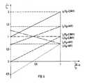
- Figur 4 sind der Eingangsstrom und die Stellerströme der Einspeiseschaltung in einem Diagramm über dem Lastverteilfaktor k dargestellt, in
Figur 5 sind der Eingangsstrom und die Stellerströme der Einspeiseschaltung im Bremsbetrieb in einem Diagramm über dem Laststrom aufgetragen und dieFigur 6 zeigt eine weitere Ausführungsform der Einspeiseschaltung für drei Antriebe.
- FIG. 1 shows a traction drive for a multi-system locomotive with the feed circuit according to the invention, in
- FIG. 2 shows a generated circuit variant of the feed circuit,
- FIG. 3 illustrates a further variant of the invention of the feed circuit, in
- FIG. 4 shows the input current and the actuator currents of the feed circuit in a diagram over the load distribution factor k, in
- Figure 5 shows the input current and the actuator currents of the feed circuit in braking mode in a diagram over the load current and the
- FIG. 6 shows a further embodiment of the feed circuit for three drives.
In Figur 1 ist ein Traktionsantrieb mit zwei Drehstrommotoren 2 und 4 für eine Mehrsystemlokomotive dargestellt. Der Drehstrommotor 2 bzw. 4 wird mittels eines Wechselrichters 6 bzw. 8 aus einem Zwischenkreiskondensator 10 bzw. 12 versorgt. Als Stromrichterventile 14 der beiden Wechselrichter 6 und 8 können Thyristoren, Transistoren und GTO-Thyristoren (Gate Turn Off) verwendet werden, wobei in dieser Darstellung GTO-Thyristoren vorgesehen sind. Die beiden Zwischenkreiskondensatoren 10 und 12 sind eingangsseitig mit einer Einspeiseschaltung 16 verknüpft.1 shows a traction drive with two three-
Die Einspeiseschaltung 16 besteht aus einem ersten und zweiten selbstgeführten vierpulsigen Stromrichter 18 und 20. Der wechselstromseitige Eingang 22 eines ersten Brückenzweiges 24 des ersten Stromrichters 18 ist über eine Induktivität 26 mit einem wechselstromseitigen Eingang 28 eines ersten Brückenzweiges 30 des zweiten Stromrichters 20 verknüpft. Ein wechselstromseitiger Eingang 32 eines zweiten Brückenzweiges 34 des ersten Stromrichters 18 ist ebenfalls über eine Induktivität 36 mit einem wechselstromseitigen Eingang 38 eines zweiten Brückenzweiges 40 des zweiten Stromrichters 20 verbunden. Als Stromrichterventile V11 bis V14 des ersten Stromrichters 18 sind GTO-Thyristoren vorgesehen, die jeweils mit einer antiparallelen Diode versehen sind. Auch die Stromrichterventile V2l bis V24 des zweiten Stromrichters 20 sind GTO-Thyristoren, die ebenfalls jeweils mit einer antiparallelen Diode versehen sind. Die beiden Stromrichter 18 und 20 sind bei Wechselspannungsversorgung mittels der Schalter S1 und S2 parallel schaltbar. Als Induktivität 26 bzw. 36 ist eine Sekundärwicklung eines Transformators 42, mit großer Streuinduktivität, auch Traktionstransformator genannt, vorgesehen. Die Primärwicklung 44 dieses Transformators 42 ist bei Gleichspannungsversorgung mittels eines Schalters S3 überbrückbar. Außerdem ist die Primärwicklung 44 über einen Schalter S4 und einem Stromabnehmer mit einem Wechselspannungsnetz verbindbar. Als Wechselspannungsnetz kann beispielsweise ein 15 kV 16 2/3 Hz- bzw. ein 25 kV 50 Hz-Netz vorgesehen sein. Ein positiver gleichstromseitiger Anschluß 46 des zweiten Stromrichters 20 ist über einen Schalter S5 und einen Stromabnehmer mit einem Gleichspannungsnetz verbindbar, wobei als Gleichspannungsnetz ein 1,5 kV- bzw. ein 3,0 kV-Netz vorgesehen sein kann. Ein negativer gleichstromseitiger Anschluß 48 des ersten Stromrichters 18 ist über einen Schalter S6 mit dem Erdpotential verbindbar. Zu diesen gleichstromseitigen Anschlüssen 46 und 48 ist ein Stützkondensator 50 elektrisch parallel geschaltet.The
Eine Steuerschaltung 52, der eine Eingangsgleichspannung UE und eine Zwischenkreis-Sollspannung UKsoll zugeführt ist, erzeugt in Abhängigkeit der Eingangsgleichspannung UE bezogen auf die Zwischenkreis-Sollspannung UKsoll Steuersignale für die Stromrichterventile V13 und V14 des ersten Stromrichters 18 und für die Stromrichterventile V21 und V22 des zweiten Stromrichters 20. Eingangsseitig weist dieses Steuerschaltung 52 einen Komparator 54 auf, dessen Ausgang mit einem Steuersatz 56 verknüpft ist. Dieser Steuersatz 56 erzeugt in Abhängigkeit der Polarität des Ausgangssignals des Komparators 54 Steuersignale für die Stromrichterventile V14 und V21 oder für die Stromrichterventile V13 und V22. Als Steuersignale stehen an den Ausgängen des Steuersatzes 56 Dauersignale an.A
Die Stromrichterventile V11 und V12 des ersten Stromrichters 18 und die Stromrichterventile V23 und V24 des zweiten Stromrichters 20 erhalten pulsbreitenmodulierte Steuersignale von einer weiteren Steuerschaltung 58. Diese Steuerschaltung 58 enthält eingangsseitig einen Differenzbildner 60, dem ein Spannungsregler 62 nachgeschaltet ist. Der Ausgang dieses Spannungsreglers 62 ist mit einem Steuersatz 64 verknüpft, der aus der vom Spannungsregler 62 erzeugten Steuerspannung uSt pulsbreitenmodulierte Steuersignale für die Stromrichterventile V11, V12, V23 und V24 der Stromrichter 18 und 20 bildet. Die Steuerspannung uSt wird mittels des Differenzbildners 60 der die Differenzspannung zwischen der Zwischenkreis-Istspannung UK1 eines Zwischenkreises und einer vorbestimmten Zwischenkreis-Sollspannung UKsoll ermittelt, gebildet und dem Spannungsregler 62 zugeführt.The converter valves V11 and V12 of the
Die Figur 2 zeigt eine erzeugte Schaltungsvariante der Einspeiseschaltung 16, wobei der erste und zweite Wechselrichter 6 und 8 mit nachgeschaltetem Drehstrommotor 2 und 4 jeweils als Widerstand 64 und 66 dargestellt sind, der jeweils elektrisch parallel zum Zwischenkreiskondensator 10 und 12 geschaltet ist. Diese Schaltungsvariante entsteht aus der Einspeisung 16 nach Figur 1, wenn das Stromrichterventil V14 des zweiten Brückenzweiges 34 des ersten Stromrichters 18 und das Stromrichterventil V21 des ersten Brückenzweiges 30 des zweiten Stromrichters 20 durchgesteuert wird. Dadurch wird der wechselstromseitige Eingang 22 des ersten Brückenzweiges 24 des ersten Stromrichters 18, auch Steiler 24 genannt, über die Induktivität 26 mit einem negativen gleichspannungsseitigen Anschluß 68 des zweiten Brückenzweiges 40 des zweiten Stromrichters 20 elektrisch leitend verbunden. Der wechselstromseitige Eingang 38 des zweiten Brückenzweiges 40 des zweiten Stromrichters 20, auch Steller 40 genannt, ist elektrisch leitend über die Induktivität 36 mit einem positiven gleichspannungsseitigen Anschluß 70 des ersten Brückenzweiges 24 des ersten Stromrichters 18 verbunden. Somit ist aus der Einspeiseschaltung 16 nach Figur 1 eine Einspeiseschaltung 16, bestehend aus zwei Aufwärtsstellern, durch Durchsteuern der Stromrichterventile V14 und V21 geworden. Solange die Eingangsgleichspannung UE größer gleich der Zwischenkreis-Sollspannung UKsoll und kleiner gleich der doppelten Zwischenkreis-Sollspannung UKsoll ist, werden die Stromrichterventile V14 und V21 von der Steuerschaltung 52 angesteuert, wodurch diese Schaltungsvariante der Einspeiseschaltung 16 erhalten bleibt.FIG. 2 shows a circuit variant of the
In Abhängigkeit der Zwischenkreis-Sollspannung UKsoll zur Zwischenkreis-Istspannung UK1 bzw. UK2 stellt sich jeweils eine Stelleraussteuerung a, die proportional zur Steuerspannung uSt des Spannungsreglers 62 ist, ein. Bei einer Eingangsgleichspannung UE gleich der Zwischenkreis-Sollspannung UKsoll stellt sich eine Stelleraussteuerung a = 1 ein, so daß die Zwischenkreis-Istspannung UK1 bzw. UK2 gleich der Zwischenkreis-Sollspannung UKsoll ist. Die Stelleraussteuerung a = 1 bedeutet, daß das Stromrichterventil V11 des ersten Stellers 24 und das Stromrichterventil V24 des zweiten Stellers 40 durchgesteuert sind. Dadurch sind die Zwischenkreiskondensatoren 10 und 12 elektrisch parallel geschaltet. Wenn nun die Eingangsgleichspannung UE gleich der doppelten Zwischenkreis-Sollspannung UKsoll ist, stellt sich eine Stelleraussteuerung a = 0 ein, so daß die Zwischenkreis-Istspannung UK1 bzw. UK2 gleich der Zwischenkreis-Sollspannung UKsoll ist. Die Stelleraussteuerung a = 0 bedeutet, daß das Stromrichterventil V12 des ersten Stellers 24 und das Stromrichterventil V23 des zweiten Stellers 40 durchgesteuert sind. Dadurch sind die Zwischenkreiskondensatoren 10 und 12 elektrisch in Reihe geschaltet. Für die Stelleraussteuerungen a, die größer Null und kleiner Eins sind, erzeugt die weitere Steuerschaltung 58 für die Stromrichterventile V11 und V12 des ersten Stellers 24 und für die Stromrichterventile V23 und V24 des zweiten Stellers 40 pulsbreitenmodulierte Steuersignale. In der Figur 4 sind der Eingangsstrom iE und die Stellerströme i₁ und i₂ in Abhängigkeit eines Lastverteilfaktors k = iL2/iL1 in einem Diagramm dargestellt. Dabei ist einmal für die Eingangsgleichspannung UE der Wert der Zwischenkreis-Sollspannung UKsoll = 2,8 kV und einmal eine Überspannung der Eingangsgleichspannung mit einem Wert UE = 4 kV angenommen worden. Außerdem ist eine unsymmetrische Lastverteilung, nämlich iL1 = konstant und iL2 variabel, angenommen worden. In Abhängigkeit der Stelleraussteuerung a > 0 ist jede beliebige Lastverteilung möglich.Depending on the intermediate circuit target voltage UKsoll to the actual intermediate circuit voltage UK1 or UK2 , an actuator control a is set, which is proportional to the control voltage uSt of the
Die Figur 3 zeigt eine weitere erzeugte Schaltungsvariante der Einspeiseschaltung 16 nach Figur 1. Diese Schaltungsvariante entsteht, wenn mittels der Steuerschaltung 52 das Stromrichterventil V13 des zweiten Brückenzweiges 34 des ersten Stromrichters 18 und das Stromrichterventil V22 des ersten Brückenzweiges 30 des zweiten Stromrichters 20 durchgeschaltet werden. Dadurch wird der wechselstromseitige Eingang 22 des ersten Brückenzweiges 24 des ersten Stromrichters 18 bzw. Stellers 24 über die Induktivität 26 mit dem positiven gleichspannungsseitigen Anschluß 46 des zweiten Stellers 40 und der wechselstromseitige Eingang 38 des zweiten Brückenzweiges 40 des zweiten Stromrichters 20 bzw. des zweiten Stellers 40 über die Induktivität 36 mit dem negativen gleichspannungsseitigen Anschluß 48 des ersten Stellers 24 elektrisch leitend verbunden. Die Stromrichterventile V13 und V22 werden genau dann von der Steuerschaltung 50 angesteuert, wenn die Eingangsgleichspannung UE kleiner ist als die Zwischenkreis-Sollspannung UKsoll. Damit an den Zwischenkreiskondensatoren 10 und 12 jeweils eine auf die Zwischenkreis-Sollspannung UKsoll geregelte Zwischenkreis-Istspannung UK1 bzw. UK2 ansteht, werden das Stromrichterventil V12 des ersten Stellers 24 und das Stromrichterventil V23 des zweiten Stellers 40 durchgesteuert. Somit sind die Zwischenkreiskondensatoren 10 und 12 elektrisch parallel geschaltet. Bei sinkender Eingangsgleichspannung UE werden die Stromrichterventile V11 und V12 des ersten Stellers 24 und die Stromrichterventile V23 und V24 des zweiten Stellers 40 derart mit pulsbreitenmodulierten Steuersignalen angesteuert, daß der Steller 24 und der Steller 40 in Verbindung mit den Induktivitäten 26 und 36 als Aufwärtssteller arbeiten, so daß an den gleichspannungsseitigen Anschlüssen 48 und 70 des ersten Stellers 24 und an den gleichspannungsseitigen Anschlüssen 68 und 46 des zweiten Stellers 40 jeweils eine auf die Zwischenkreis-Sollspannung UKsoll geregelte Zwischenkreis-Istspannung UK1 und UK2 ansteht.FIG. 3 shows a further circuit variant of the
Mit der Einspeiseschaltung 16 nach Figur 1 bzw. der Schaltungsvarianten nach Figuren 2 und 3 ist auch eine Nutzbremsung möglich. In Figur 5 sind der Eingangsstrom iE und die Stellerströme i₁ und i₂ in einem Diagramm über dem Laststrom iL2 aufgetragen, wobei ein Laststrom IL1 = -500 A und eine Zwischenkreisspannung UK1 = UK2 = 2,8 kV angenommen ist.With the
Somit erhält man mit der Einspeiseschaltung 16 nach Figur 1 einen Gleichspannungsstellbereich ohne Umschaltung von Eingangsgleichspannung UE größer gleich Null bis Eingangsgleichspannung UE kleiner gleich doppelter Wert der Zwischenkreis-Sollspannung UKsoll.Thus, with the
Bei Wechselspannungseinspeisung aus einem 15 kV 16 2/3 Hz- bzw. 15 kV 50 Hz-Netz werden die Schalter S3, S5 und S6 geöffnet und die Schalter S1, S2 und S4 geschlossen. Dadurch sind der erste Stromrichter 18 und der zweite Stromrichter 20 elektrisch parallel geschaltet, wobei die eine Sekundärwicklung 26 des Transformators 42 den wechselstromseitigen Eingang 22 des ersten Brückenzweiges 24 des ersten Stromrichters 18 mit dem wechselstromseitigen Eingang 28 des ersten Brückenzweiges 30 des zweiten Stromrichters 20 und die Sekundärwicklung 36 des Transformators 42 den wechselstromseitigen Eingang 32 des zweiten Brückenzweiges 34 des ersten Stromrichters 18 mit dem wechselstromseitigen Eingang 39 des zweiten Brückenzweiges 40 des zweiten Stromrichters 20 elektrisch leitend verbinden. Dadurch bilden bei Wechselspannungseinspeisung der erste Brückenzweig 24 des ersten Stromrichters 18 und der erste Brückenzweig 30 des zweiten Stromrichters 20 einen ersten Vierquadrantensteller und der zweite Brückenzweig 34 des ersten Stromrichters 18 und der zweite Brückenzweig 40 des zweiten Stromrichters 20 einen zweiten Vierquadrantensteller. Diese beiden Vierquadrantensteller speisen in eine gemeinsame Gleichspannungsschiene, an der die beiden Zwischenkreiskondensatoren 10 und 12 mit nachgeschalteten Wechselrichtern 6 und 8 elektrisch parallel angeschlossen sind.When AC voltage is fed in from a 15 kV 16 2/3 Hz or 15 kV 50 Hz network, switches S3, S5 and S6 are opened and switches S1, S2 and S4 are closed. As a result, the
Durch die Gestaltung der erfindungsgemäßen Einspeiseschaltung 16 für eine Mehrsystemlokomotive erhält man bei Gleichspannungseinspeisung und bei Wechselspannungseinspeisung immer eine geregelte Zwischenkreisspannung UK1 und UK2.By designing the
In Figur 6 ist ein Traktionsantrieb mit drei Wechselstrommotoren dargestellt, wobei jeweils der Wechselrichter mit nachgeschalteten Wechselstrommotor als Widerstand 64, 66 und 72 dargestellt ist. Der Traktionsantrieb gemäß Figur 1 ist somit um einen Antrieb erweitert worden. Deshalb sind gleiche Bauelemente der Figur 1 und der Figur 6 mit denselben Bezugszeichen versehen. Gegenüber der Ausführungsform nach Figur 1 ist eine zweite Einspeiseschaltung 74 vorgesehen, deren erster Stromrichter 76 elektrisch parallel zum zweiten Stromrichter 20 der Einspeiseschaltung 16 geschaltet ist. Der weitere Aufbau der Einspeiseschaltung 74 entspricht dem Aufbau der Einspeiseschaltung 16. Auch die Brückenzweige 78, 80, 82 und 84 der beiden Stromrichter 76 und 86 der Einspeiseschaltung 74 sind mittels Induktivitäten 88 und 90 untereinander verbunden. Mit Hilfe zweier weiterer Schalter S7 und S8 sind die Stromrichter 76 und 86 elektrisch parallel schaltbar, sobald eine Wechselspannung eingespeist wird. Durch die Erweiterung des Traktionsantriebs nach Figur 1 auf drei Antriebsmotoren kann die erfindungsgemäße Einspeiseschaltung 16 und 74 auch bei Mehrsystemlokomotiven verwendet werden, bei denen jeweils drei Wechselstrommotoren in einem Drehgestell untergebracht sind.FIG. 6 shows a traction drive with three AC motors, the inverter with a connected AC motor being shown as a
Claims (5)
Translated fromGermandadurch gekennzeichnet,
characterized,
Priority Applications (7)
| Application Number | Priority Date | Filing Date | Title |
|---|---|---|---|
| EP89103111AEP0383971A1 (en) | 1989-02-22 | 1989-02-22 | Supply circuit for a multisystem locomotive |
| AT90102421TATE98575T1 (en) | 1989-02-22 | 1990-02-07 | FEED CIRCUIT FOR A MULTI-SYSTEM LOCOMOTIVE. |
| ES199090102421TES2046546T3 (en) | 1989-02-22 | 1990-02-07 | POWER SUPPLY CIRCUIT FOR A MULTISYSTEM LOCOMOTIVE. |
| DE90102421TDE59003822D1 (en) | 1989-02-22 | 1990-02-07 | Feed circuit for a multi-system locomotive. |
| EP90102421AEP0384222B1 (en) | 1989-02-22 | 1990-02-07 | Supply circuit for a multisystem locomotive |
| DK90102421.6TDK0384222T3 (en) | 1989-02-22 | 1990-02-07 | Supply circuit for a multi-system locomotive |
| PT93223APT93223B (en) | 1989-02-22 | 1990-02-21 | FOOD CIRCUIT FOR A MULTI-SYSTEM LOCOMOTIVE |
Applications Claiming Priority (1)
| Application Number | Priority Date | Filing Date | Title |
|---|---|---|---|
| EP89103111AEP0383971A1 (en) | 1989-02-22 | 1989-02-22 | Supply circuit for a multisystem locomotive |
Publications (1)
| Publication Number | Publication Date |
|---|---|
| EP0383971A1true EP0383971A1 (en) | 1990-08-29 |
Family
ID=8200993
Family Applications (2)
| Application Number | Title | Priority Date | Filing Date |
|---|---|---|---|
| EP89103111AWithdrawnEP0383971A1 (en) | 1989-02-22 | 1989-02-22 | Supply circuit for a multisystem locomotive |
| EP90102421AExpired - LifetimeEP0384222B1 (en) | 1989-02-22 | 1990-02-07 | Supply circuit for a multisystem locomotive |
Family Applications After (1)
| Application Number | Title | Priority Date | Filing Date |
|---|---|---|---|
| EP90102421AExpired - LifetimeEP0384222B1 (en) | 1989-02-22 | 1990-02-07 | Supply circuit for a multisystem locomotive |
Country Status (6)
| Country | Link |
|---|---|
| EP (2) | EP0383971A1 (en) |
| AT (1) | ATE98575T1 (en) |
| DE (1) | DE59003822D1 (en) |
| DK (1) | DK0384222T3 (en) |
| ES (1) | ES2046546T3 (en) |
| PT (1) | PT93223B (en) |
Cited By (18)
| Publication number | Priority date | Publication date | Assignee | Title |
|---|---|---|---|---|
| DE4224795A1 (en)* | 1991-08-08 | 1993-02-11 | Siemens Ag | Generation of stable regulating action for power supply circuit e.g. for electric railway - comparing output with reference valve to provide error, and adding to control signals to apply correction for adjustment of supply |
| DE4138256A1 (en)* | 1991-11-21 | 1993-05-27 | Asea Brown Boveri | METHOD AND CIRCUIT FOR FORMING ELECTRICAL ENERGY |
| DE4238197A1 (en)* | 1992-11-12 | 1994-05-19 | Abb Patent Gmbh | Multi-system vehicle |
| EP0637121A1 (en)* | 1993-07-28 | 1995-02-01 | ABBPATENT GmbH | Power converter assembly for the supply of an intermediate DC circuit |
| EP0657321A1 (en)* | 1993-12-13 | 1995-06-14 | Gec Alsthom Transport Sa | High availability multi-current supply system for a locomotive |
| EP0666641A1 (en)* | 1994-02-07 | 1995-08-09 | Siemens Aktiengesellschaft | Supply circuit for a multisystem locomotive |
| EP0666640A1 (en)* | 1994-02-07 | 1995-08-09 | Siemens Aktiengesellschaft | Supply circuit for a DC locomotive |
| EP0756221A3 (en)* | 1995-07-21 | 1998-01-07 | ABB Daimler-Benz Transportation (Italia) S.p.A. | Method and apparatus for controlling the tension in circuits for transport vehicles |
| DE19742429C1 (en)* | 1997-09-25 | 1999-01-07 | Siemens Ag | Circuit arrangement e.g. for supplying electrical traction motor in multi-stage vehicle traction devices |
| CN101141108B (en)* | 2007-01-10 | 2010-10-13 | 龚秋声 | DC motor bridge full thyristor speeder |
| EP2515424A3 (en)* | 2011-04-20 | 2016-03-09 | Platinum GmbH | Direct current converter |
| EP1841616B1 (en) | 2005-01-27 | 2016-12-21 | Alstom Grid SAS | Transformer for multicurrent motor vehicle |
| CN106379339A (en)* | 2016-09-30 | 2017-02-08 | 株洲中车时代电气股份有限公司 | Double heading control circuit device and method for implementing locomotive wireless double heading |
| US9673630B2 (en) | 2007-10-15 | 2017-06-06 | Ampt, Llc | Protected conversion solar power system |
| EP3176933A1 (en)* | 2013-03-15 | 2017-06-07 | Ampt, Llc | High efficiency interleaved solar power supply system |
| US10032939B2 (en) | 2009-10-19 | 2018-07-24 | Ampt, Llc | DC power conversion circuit |
| US10116140B2 (en) | 2013-03-15 | 2018-10-30 | Ampt, Llc | Magnetically coupled solar power supply system |
| US10326282B2 (en) | 2009-04-17 | 2019-06-18 | Ampt, Llc | Safety methods and apparatus for adaptive operation of solar power systems |
Families Citing this family (5)
| Publication number | Priority date | Publication date | Assignee | Title |
|---|---|---|---|---|
| ATE126947T1 (en)* | 1991-05-24 | 1995-09-15 | Siemens Ag | CONVERTER ARRANGEMENT. |
| DE19756245C1 (en)* | 1997-12-17 | 1999-05-27 | Siemens Ag | Power supply circuit arrangement e.g. for AC/DC drive railway locomotives |
| DE102010039697A1 (en)* | 2010-08-24 | 2012-03-01 | Siemens Aktiengesellschaft | Multi-system traction converter |
| FR2993729B1 (en)* | 2012-07-18 | 2015-06-19 | Sncf | POWER SUPPLY CIRCUIT FOR A RAILWAY VEHICLE, TRACTION CHAIN, AND RAILWAY VEHICLE COMPRISING SUCH A CIRCUIT. |
| DE202014010539U1 (en)* | 2014-11-13 | 2015-11-27 | Siemens Aktiengesellschaft | Electrical circuit and rail vehicle |
Citations (1)
| Publication number | Priority date | Publication date | Assignee | Title |
|---|---|---|---|---|
| EP0204690B1 (en)* | 1985-05-31 | 1989-11-02 | ELIN-UNION Aktiengesellschaft für elektrische Industrie | Supply circuit |
Family Cites Families (1)
| Publication number | Priority date | Publication date | Assignee | Title |
|---|---|---|---|---|
| EP0330055B1 (en)* | 1988-02-22 | 1992-12-02 | Siemens Aktiengesellschaft | Process for the symmetrical subdivision of a dc voltage in series with a voltage divider consisting of n capacitors, and circuitry for carrying out the process |
- 1989
- 1989-02-22EPEP89103111Apatent/EP0383971A1/ennot_activeWithdrawn
- 1990
- 1990-02-07ESES199090102421Tpatent/ES2046546T3/ennot_activeExpired - Lifetime
- 1990-02-07DKDK90102421.6Tpatent/DK0384222T3/enactive
- 1990-02-07ATAT90102421Tpatent/ATE98575T1/ennot_activeIP Right Cessation
- 1990-02-07EPEP90102421Apatent/EP0384222B1/ennot_activeExpired - Lifetime
- 1990-02-07DEDE90102421Tpatent/DE59003822D1/ennot_activeExpired - Fee Related
- 1990-02-21PTPT93223Apatent/PT93223B/ennot_activeIP Right Cessation
Patent Citations (1)
| Publication number | Priority date | Publication date | Assignee | Title |
|---|---|---|---|---|
| EP0204690B1 (en)* | 1985-05-31 | 1989-11-02 | ELIN-UNION Aktiengesellschaft für elektrische Industrie | Supply circuit |
Non-Patent Citations (2)
| Title |
|---|
| ELEKTRISCHE BAHNEN. vol. 85, no. 11, November 1987, MUNCHEN DE Seiten 367 - 372; G. PROKISCH: "DIE ZWEIFREQUENZLOKOMOTIVE Rh 1146 DER OESTERREICHISCHEN BUNDESBAHNEN IN DREHSTROMANTRIEBSTECHNIK"* |
| ELEKTRISCHE BAHNEN. vol. 86, no. 1, Januar 1988, MUNCHEN DE Seiten 22 - 39; H. GATHMANN ET AL: "UEBERSICHT UEBER DIE JUENGSTEN ENTWICKLUNGEN DER DREHSTROMANTRIEBSTECHNIK BEI ELEKTRISCHEN BAHNEN"* |
Cited By (38)
| Publication number | Priority date | Publication date | Assignee | Title |
|---|---|---|---|---|
| DE4224795A1 (en)* | 1991-08-08 | 1993-02-11 | Siemens Ag | Generation of stable regulating action for power supply circuit e.g. for electric railway - comparing output with reference valve to provide error, and adding to control signals to apply correction for adjustment of supply |
| DE4138256A1 (en)* | 1991-11-21 | 1993-05-27 | Asea Brown Boveri | METHOD AND CIRCUIT FOR FORMING ELECTRICAL ENERGY |
| DE4238197A1 (en)* | 1992-11-12 | 1994-05-19 | Abb Patent Gmbh | Multi-system vehicle |
| EP0637121A1 (en)* | 1993-07-28 | 1995-02-01 | ABBPATENT GmbH | Power converter assembly for the supply of an intermediate DC circuit |
| US5629591A (en)* | 1993-12-13 | 1997-05-13 | Gec Alsthom Transport Sa | High-availability multicurrent power supply system for the traction unit of a railway locomotive |
| EP0657321A1 (en)* | 1993-12-13 | 1995-06-14 | Gec Alsthom Transport Sa | High availability multi-current supply system for a locomotive |
| FR2713565A1 (en)* | 1993-12-13 | 1995-06-16 | Gec Alsthom Transport Sa | High availability multicurrent power system for railway locomotive. |
| EP0666641A1 (en)* | 1994-02-07 | 1995-08-09 | Siemens Aktiengesellschaft | Supply circuit for a multisystem locomotive |
| EP0666640A1 (en)* | 1994-02-07 | 1995-08-09 | Siemens Aktiengesellschaft | Supply circuit for a DC locomotive |
| EP0756221A3 (en)* | 1995-07-21 | 1998-01-07 | ABB Daimler-Benz Transportation (Italia) S.p.A. | Method and apparatus for controlling the tension in circuits for transport vehicles |
| DE19742429C1 (en)* | 1997-09-25 | 1999-01-07 | Siemens Ag | Circuit arrangement e.g. for supplying electrical traction motor in multi-stage vehicle traction devices |
| EP1841616B1 (en) | 2005-01-27 | 2016-12-21 | Alstom Grid SAS | Transformer for multicurrent motor vehicle |
| CN101141108B (en)* | 2007-01-10 | 2010-10-13 | 龚秋声 | DC motor bridge full thyristor speeder |
| US11070062B2 (en) | 2007-10-15 | 2021-07-20 | Ampt, Llc | Photovoltaic conversion systems |
| US11070063B2 (en) | 2007-10-15 | 2021-07-20 | Ampt, Llc | Method for alternating conversion solar power |
| US9673630B2 (en) | 2007-10-15 | 2017-06-06 | Ampt, Llc | Protected conversion solar power system |
| US12027867B2 (en) | 2007-10-15 | 2024-07-02 | Ampt, Llc | Coordinated converter reactively altering disabling photovoltaic electrical energy power system |
| US12027869B2 (en) | 2007-10-15 | 2024-07-02 | Ampt, Llc | Optimized photovoltaic conversion configuration |
| US12003110B2 (en) | 2007-10-15 | 2024-06-04 | Ampt, Llc | Optimized conversion system |
| US11289917B1 (en) | 2007-10-15 | 2022-03-29 | Ampt, Llc | Optimized photovoltaic conversion system |
| US10326283B2 (en) | 2007-10-15 | 2019-06-18 | Ampt, Llc | Converter intuitive photovoltaic electrical energy power system |
| US11228182B2 (en) | 2007-10-15 | 2022-01-18 | Ampt, Llc | Converter disabling photovoltaic electrical energy power system |
| US10608437B2 (en) | 2007-10-15 | 2020-03-31 | Ampt, Llc | Feedback based photovoltaic conversion systems |
| US10886746B1 (en) | 2007-10-15 | 2021-01-05 | Ampt, Llc | Alternating conversion solar power system |
| US10938219B2 (en) | 2009-04-17 | 2021-03-02 | Ampt, Llc | Dynamic methods and apparatus for adaptive operation of solar power systems |
| US10326282B2 (en) | 2009-04-17 | 2019-06-18 | Ampt, Llc | Safety methods and apparatus for adaptive operation of solar power systems |
| US11411126B2 (en) | 2009-10-19 | 2022-08-09 | Ampt, Llc | DC power conversion circuit |
| US12034087B2 (en) | 2009-10-19 | 2024-07-09 | Ampt, Llc | Solar panel power conversion circuit |
| US10032939B2 (en) | 2009-10-19 | 2018-07-24 | Ampt, Llc | DC power conversion circuit |
| US10714637B2 (en) | 2009-10-19 | 2020-07-14 | Ampt, Llc | DC power conversion circuit |
| EP2515424A3 (en)* | 2011-04-20 | 2016-03-09 | Platinum GmbH | Direct current converter |
| US10116140B2 (en) | 2013-03-15 | 2018-10-30 | Ampt, Llc | Magnetically coupled solar power supply system |
| US11967653B2 (en) | 2013-03-15 | 2024-04-23 | Ampt, Llc | Phased solar power supply system |
| US11121556B2 (en) | 2013-03-15 | 2021-09-14 | Ampt, Llc | Magnetically coupled solar power supply system for battery based loads |
| EP3176933A1 (en)* | 2013-03-15 | 2017-06-07 | Ampt, Llc | High efficiency interleaved solar power supply system |
| US12057514B2 (en) | 2013-03-15 | 2024-08-06 | Ampt, Llc | Converter controlled solar power supply system for battery based loads |
| CN106379339B (en)* | 2016-09-30 | 2018-12-11 | 株洲中车时代电气股份有限公司 | For realizing the device and method for the reconnection control circuit that locomotive wirelessly joins again |
| CN106379339A (en)* | 2016-09-30 | 2017-02-08 | 株洲中车时代电气股份有限公司 | Double heading control circuit device and method for implementing locomotive wireless double heading |
Also Published As
| Publication number | Publication date |
|---|---|
| PT93223B (en) | 1996-01-31 |
| EP0384222A1 (en) | 1990-08-29 |
| DE59003822D1 (en) | 1994-01-27 |
| EP0384222B1 (en) | 1993-12-15 |
| PT93223A (en) | 1990-08-31 |
| ES2046546T3 (en) | 1994-02-01 |
| ATE98575T1 (en) | 1994-01-15 |
| DK0384222T3 (en) | 1994-04-11 |
Similar Documents
| Publication | Publication Date | Title |
|---|---|---|
| EP0384222B1 (en) | Supply circuit for a multisystem locomotive | |
| EP0832006B1 (en) | High voltage power converter system | |
| EP2586646B1 (en) | Electrical power supply assembly for drive units, for operating a rail vehicle on electrical supply networks | |
| DE102010039699A1 (en) | Drive system for a rail vehicle | |
| EP0597409B1 (en) | Multisystem vehicle | |
| DE3817652C2 (en) | ||
| DE2461191B2 (en) | SINGLE-PHASE BRIDGE CIRCUIT CONSTRUCTED FROM FOUR CONTROLLED RECTIFIER VALVES, FOR OPTIONAL OPERATION AS AC-DC CONVERTER OR DC CHOPPER | |
| EP0204690B1 (en) | Supply circuit | |
| EP0670236A1 (en) | Power supply device for train passenger coaches | |
| EP0300392B1 (en) | Rectifier circuit for supplying dc voltage to an intermediate circulating current circuit | |
| DE3915211C2 (en) | ||
| DE4344709C2 (en) | Process for converting DC or AC voltages of different sizes into an arbitrarily specified voltage | |
| DE19817752A1 (en) | Electrical circuit arrangement for supplying an electrical drive system | |
| DE4018930A1 (en) | Bridge circuit for pulse operated inverter - switches power semiconductors in overlapping sequence using inductively short-circuited feed voltages | |
| EP0534242B1 (en) | Method to reduce voltage oscillations of a neutral point connection of a three-level inverter | |
| EP0326681B1 (en) | Arc welding apparatus for direct and alternating current supply | |
| DE4325275A1 (en) | Converter circuit for feeding a DC link | |
| EP0534285B1 (en) | Filter circuit | |
| DE2714152C2 (en) | Circuit arrangement for generating voltages with alternating polarity from a direct voltage | |
| DE4403762C1 (en) | Feed circuit for a multi-system locomotive | |
| DE2853619A1 (en) | RECTIFIER ARRANGEMENT | |
| DE2646745C3 (en) | Circuit arrangement for feeding a DC voltage consumer | |
| DE3907940A1 (en) | Method for symmetrising the voltage sharing in power converters having multi-point connection | |
| DE2943324A1 (en) | Polyphase converter system - uses currents or voltages made up to given duration at load by superimposition | |
| DE10323218A1 (en) | High voltage converter for rail traction, is formed from input current converter based on series-connected power semiconductor switches, intermediate circuit and high-voltage inverter |
Legal Events
| Date | Code | Title | Description |
|---|---|---|---|
| PUAI | Public reference made under article 153(3) epc to a published international application that has entered the european phase | Free format text:ORIGINAL CODE: 0009012 | |
| AK | Designated contracting states | Kind code of ref document:A1 Designated state(s):DE | |
| STAA | Information on the status of an ep patent application or granted ep patent | Free format text:STATUS: THE APPLICATION IS DEEMED TO BE WITHDRAWN | |
| 18D | Application deemed to be withdrawn | Effective date:19900223 |