EP0381202B1 - Shaft lock device with coil spring inserted in rotational shaft of hinge mechanism and portable information processing apparatus with shaft lock device - Google Patents
Shaft lock device with coil spring inserted in rotational shaft of hinge mechanism and portable information processing apparatus with shaft lock deviceDownload PDFInfo
- Publication number
- EP0381202B1 EP0381202B1EP90101936AEP90101936AEP0381202B1EP 0381202 B1EP0381202 B1EP 0381202B1EP 90101936 AEP90101936 AEP 90101936AEP 90101936 AEP90101936 AEP 90101936AEP 0381202 B1EP0381202 B1EP 0381202B1
- Authority
- EP
- European Patent Office
- Prior art keywords
- rotational shaft
- shaft
- coil spring
- diameter
- display device
- Prior art date
- Legal status (The legal status is an assumption and is not a legal conclusion. Google has not performed a legal analysis and makes no representation as to the accuracy of the status listed.)
- Expired - Lifetime
Links
Images


Classifications
- F—MECHANICAL ENGINEERING; LIGHTING; HEATING; WEAPONS; BLASTING
- F16—ENGINEERING ELEMENTS AND UNITS; GENERAL MEASURES FOR PRODUCING AND MAINTAINING EFFECTIVE FUNCTIONING OF MACHINES OR INSTALLATIONS; THERMAL INSULATION IN GENERAL
- F16D—COUPLINGS FOR TRANSMITTING ROTATION; CLUTCHES; BRAKES
- F16D49/00—Brakes with a braking member co-operating with the periphery of a drum, wheel-rim, or the like
- F16D49/02—Brakes with a braking member co-operating with the periphery of a drum, wheel-rim, or the like shaped as a helical band or coil with more than one turn, with or without intensification of the braking force by the tension of the band or contracting member
- F—MECHANICAL ENGINEERING; LIGHTING; HEATING; WEAPONS; BLASTING
- F16—ENGINEERING ELEMENTS AND UNITS; GENERAL MEASURES FOR PRODUCING AND MAINTAINING EFFECTIVE FUNCTIONING OF MACHINES OR INSTALLATIONS; THERMAL INSULATION IN GENERAL
- F16D—COUPLINGS FOR TRANSMITTING ROTATION; CLUTCHES; BRAKES
- F16D7/00—Slip couplings, e.g. slipping on overload, for absorbing shock
- F16D7/02—Slip couplings, e.g. slipping on overload, for absorbing shock of the friction type
- F16D7/022—Slip couplings, e.g. slipping on overload, for absorbing shock of the friction type with a helical band or equivalent member co-operating with a cylindrical torque limiting coupling surface
- E—FIXED CONSTRUCTIONS
- E05—LOCKS; KEYS; WINDOW OR DOOR FITTINGS; SAFES
- E05D—HINGES OR SUSPENSION DEVICES FOR DOORS, WINDOWS OR WINGS
- E05D11/00—Additional features or accessories of hinges
- E05D11/08—Friction devices between relatively-movable hinge parts
- E05D11/082—Friction devices between relatively-movable hinge parts with substantially radial friction, e.g. cylindrical friction surfaces
- E05D11/084—Friction devices between relatively-movable hinge parts with substantially radial friction, e.g. cylindrical friction surfaces the friction depending on direction of rotation or opening angle of the hinge
- E—FIXED CONSTRUCTIONS
- E05—LOCKS; KEYS; WINDOW OR DOOR FITTINGS; SAFES
- E05Y—INDEXING SCHEME ASSOCIATED WITH SUBCLASSES E05D AND E05F, RELATING TO CONSTRUCTION ELEMENTS, ELECTRIC CONTROL, POWER SUPPLY, POWER SIGNAL OR TRANSMISSION, USER INTERFACES, MOUNTING OR COUPLING, DETAILS, ACCESSORIES, AUXILIARY OPERATIONS NOT OTHERWISE PROVIDED FOR, APPLICATION THEREOF
- E05Y2999/00—Subject-matter not otherwise provided for in this subclass
Definitions
- the present inventionrelates to a shaft lock device for a hinge mechanism with a rotational shaft, and to a portable information processing apparatus provided with the shaft lock device.
- desktop apparatusesare being replaced by laptop apparatuses that are small, light, and portable.
- laptop type information processing apparatusesgenerally comprise a main body, which contains a keyboard, a disk drive, etc., and a display unit pivotably supported on the main body by means of a hinge mechanism.
- the hinge mechanismhas a shaft lock device for locking the display unit at a desired angular position.
- the lock devicecomprises a metal rotational shaft supported so as to rotate in response to the pivoting motion of the display unit, and a coil spring rigidly wound around the rotational shaft and having one end fixed to the main body of the apparatus.
- One end of the shaftis engaged with a first bracket of the display unit so that the shaft rotates along with the display unit.
- the other end of the shaftis rotatably supported by a second bracket attached to the main body.
- One end of the coil springis fixed to the second bracket.
- the coil spring with a predetermined lengthis wound around the rotational shaft, and the shaft is fixed at its one end to the first bracket of the display unit and is rotatably supported at its other end by the second bracket of the main body. Therefore, the entire length of the lock device is always larger than that of the coil spring. Further, under the mechanical strength of the device, the rotational shaft should be made of a metal, thus increasing the weight of the device.
- the present inventionhas been contrived in consideration of these circumstances, and its object is to provide a compact and light shaft lock device, and a portable information processing apparatus provided therewith.
- a deviceis constructed utilizing the slipping performance of a coil spring. If a coil spring is subjected to stress in its coiling direction, its coil diameter is reduced. If it is subjected to stress in the direction opposite the coiling direction, on the other hand, the coil diameter increases.
- the coil springis located in a rotatable hollow member, whose rotation is dampened by applying the coil spring with stress in the coiling direction or in the opposite direction to control the frictional force between the spring and the member.
- the shaft lock device of the present inventioncomprises: a cylindrical rotational shaft having outer and inner circumferential surfaces coaxial with each other; a first member supporting one end portion of the rotational shaft so that the shaft is rotatable around the axis thereof; a second member fixed to the other end portion of the rotational shaft and pivotable integrally with the rotational shaft; and a coil spring coiled in a predetermined direction and having a coil diameter greater than the inner diameter of the rotational shaft, the coil spring being arranged in the rotational shaft along the axial direction thereof while the outer surface of the coil spring is in contact with the inner circumferential surface of the rotational shaft, and having one end anchored to the first member and a free end situated on the second member side, the coil spring being adapted to expand in its radial direction to restrain the rotational shaft from rotating, when the second member is pivoted in the direction opposite the coiling direction, and adapted to contract in its radial direction to allow the rotational shaft to rotate, when the second member is pivoted in the coiling direction.
- an electronic apparatusis claimed in claim 7, which comprises among others the aforementioned shaft lock device.
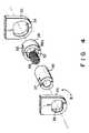
- Figs. 1 to 5show a laptop personal computer with a shaft lock device according to a first embodiment of the present invention, in which:
- Figs. 1 to 3show laptop personal computer 10 which is provided with a shaft lock device according to a first embodiment of the present invention.
- Computer 10comprises main body 12 and display unit 15 which is pivotably supported on the main body by means of a pair of shaft lock devices 22 (mentioned later).
- Main body 12is provided with keyboard 13, floppy disk drive 14, etc.
- Display unit 15includes flat-plate display 16, outer cover 15a covering the back side of display 16, and inner cover 15b having a display window.
- Unit 15further includes a pair of legs 20.
- On the central portion of the upper surface of main body 12is mounted cable duct 19 through which cables extend from main body 12 to display unit 15.
- Duct 19is rotatably supported by legs 20.
- Display unit 15 and main body 12are provided with latch 17 and notch 18, respectively, which cooperate with each other.
- latch 17engages notch 18, thereby locking unit 15 in the closed position.
- An operatorcan disengage latch 17 from notch 18 by pressing the latch.
- the operatorcan pivot display unit 15 between the closed position and an open position, in which keyboard 13 is ready for operation, while observing display 16.
- Computer 10is provided with shaft lock devices 22 which are used to hold display unit 15 at a desired angle in the open position.
- each shaft lock device 22includes bracket 24 for use as a second member. Brackets 24 are fixed to their corresponding legs 20 of display unit 15 by screws 24a and situated on either side of duct 19.
- each shaft lock device 22includes cylindrical rotational shaft 26, which has inner and outer circumferential surfaces 26b and 26a, coaxial with each other.
- the right-hand end portion of shaft 26is rotatably supported by cylindrical support member 28 for use as a first member, which is fixed to its corresponding bracket 30 of main body 12.
- Support hole 32which has an inner diameter substantially equal to the outer diameter of shaft 26, is formed in support member 28.
- the right-hand end portion of support member 28is formed as retaining portion 33, which has an oblate cross section. The retaining portion is fitted in oblate retaining hole 34 of the corresponding bracket 30.
- support member 28is unrotatably fixed to main body 12 through bracket 30, and the right-hand end portion of rotational shaft 26 is rotatably fitted in support hole 32 of its corresponding support member 28. In this manner, shaft 26 is supported to be rotatable around its central axis by member 28.
- shaft 26is formed as retaining portion 37, which has an oblate cross section. Retaining portion 37 is fitted in oblate engaging hole 36 formed in its corresponding bracket 24. Thus, shaft 26 is coupled with bracket 24 and prevented from rotating relative to bracket 24. Accordingly, when display unit 15 is opened or closed, shaft 26 is rotated around its central axis together with display unit 15.
- Coil spring 38is coaxially arranged inside shaft 26. It is coiled so that its coil diameter is a little greater than the inner diameter of shaft 26. Thus, spring 38 is inserted in shaft 26 while being contracted in its radial direction, so that the outer surface of the spring is always pressed against inner circumferential surface 26b of shaft 26 by its own restoring force. Right-hand end 38a of spring 38 is fitted in engaging groove 40, formed on the right end of support member 28, while the left-hand end of the spring is free. Spring 38 is coiled in the direction of arrow B in Fig. 4, which is coincident with the closing direction (direction of arrow B in Fig. 2) of display unit 15.
- Cable 50 for electrically connecting main body 12 with display unit 15extends through rotational shaft 26.
- latch 17is first unfastened, and display unit 15 is then pivoted in the direction of arrow A in Fig. 2 from the closed position shown in Fig. 1, by means of a certain pivoting force.
- rotational shafts 26 of shaft lock devices 22rotate together with unit 15, also in the direction of arrow A.
- Coil spring 38is contractedly squeezed in shaft 26, while its one end 38a is fixed to support member 28.
- frictional forceis produced between inner circumferential surface 26b of shaft 26 and the outer surface of spring 38 by the expansive force of the spring.
- spring 38also rotates in the direction of arrow A in Fig. 4.
- display unit 15can be easily locked in any desired angular position. If an excessive pivoting force is applied to unit 15, however, spring 38 slips, so that shaft 26 is unlocked. Accordingly, bracket 24 and shaft 26 can be prevented from being broken or bent, and spring 38 can be protected against snapping.
- the pivoting force to cause the slip of spring 38may be adjusted to a desired value by changing the number of turns and coil diameter of spring 38.
- display unit 15can be securely locked to any desired angular position by utilizing the increase or decrease of the coil diameter of coil spring 38. Also, unit 15 can be easily returned to the closed position without using any special unlocking mechanism. Thus, the operating efficiency of the computer is greatly improved.
- coil spring 38is housed in rotational shaft 26, a compact shaft lock device can be realized. Specifically, the distance between brackets 24 and 30 supporting rotational shaft 26 can be shorter than the axial length of coil spring 38, thereby reducing the axial length of shaft lock device 22.
- Fig. 7shows a shaft lock device according to a second embodiment of the present invention.
- Like reference numeralsrefer to like portions throughout the drawings.
- support hole 32 of support member 28is stepped. More specifically, hole 32 has large-diameter portion 32a on the left-end side and small-diameter portion 32b on the right-end side.
- the diameter of portion 32ais substantially equal to the outer diameter of rotational shaft 26, while that of portion 32b is substantially equal to the inner diameter of the shaft.
- the right-hand end portion of shaft 26is rotatably fitted in large-diameter portion 32a.
- the left- and right-hand end portions of coil spring 38are located inside shaft 26 and small-diameter portion 32b, respectively.
- the coil diameter of spring 38is a little greater than the inner diameter of shaft 26 and the diameter of portion 32b.
- spring 38is always pressed against the respective inner circumferential surfaces of shaft 26 and small-diameter portion 32b. Both ends of spring 38 are free ends, and the spring is fixedly retained by support member 28, by pressing its right-hand end portion against the inner circumferential surface of small-diameter portion 32b.
- the second embodimentcan provide the same advantages as the first embodiment.
- Support member 28may be formed of relatively soft material, such as plastic.
- the friction between spring 38 and the inner circumferential surface of small-diameter portion 32bis lowered. Since both ends of spring 38 are free ends, moreover, spring 38 can slip by means of a smaller pivoting force than in the first embodiment.
- display unit 15can be opened or closed with a relatively small pivoting force, so that the operating efficiency of computer 10 is further improved.
- right-hand end 38a of coil spring 38may be fixedly fitted in engaging groove 40 bored through support member 28, as shown in Fig. 8.
Landscapes
- Engineering & Computer Science (AREA)
- General Engineering & Computer Science (AREA)
- Mechanical Engineering (AREA)
- Pivots And Pivotal Connections (AREA)
- Hinge Accessories (AREA)
- Braking Arrangements (AREA)
- Casings For Electric Apparatus (AREA)
- Devices For Indicating Variable Information By Combining Individual Elements (AREA)
Description
- The present invention relates to a shaft lock device for a hinge mechanism with a rotational shaft, and to a portable information processing apparatus provided with the shaft lock device.
- Presently, in the field of a personal computer or a ward processor, desktop apparatuses are being replaced by laptop apparatuses that are small, light, and portable.
- As disclosed in US-A- 4,864,523, laptop type information processing apparatuses generally comprise a main body, which contains a keyboard, a disk drive, etc., and a display unit pivotably supported on the main body by means of a hinge mechanism.
- The hinge mechanism has a shaft lock device for locking the display unit at a desired angular position. The lock device comprises a metal rotational shaft supported so as to rotate in response to the pivoting motion of the display unit, and a coil spring rigidly wound around the rotational shaft and having one end fixed to the main body of the apparatus. One end of the shaft is engaged with a first bracket of the display unit so that the shaft rotates along with the display unit. The other end of the shaft is rotatably supported by a second bracket attached to the main body. One end of the coil spring is fixed to the second bracket. The operation of the lock device with the above-mentioned structure is disclosed, e.g., in US-A- 3,064,766.
- With the conventional shaft lock device, the coil spring with a predetermined length is wound around the rotational shaft, and the shaft is fixed at its one end to the first bracket of the display unit and is rotatably supported at its other end by the second bracket of the main body. Therefore, the entire length of the lock device is always larger than that of the coil spring. Further, under the mechanical strength of the device, the rotational shaft should be made of a metal, thus increasing the weight of the device.
- The present invention has been contrived in consideration of these circumstances, and its object is to provide a compact and light shaft lock device, and a portable information processing apparatus provided therewith.
- In order to achieve the above object, a device according to the present invention is constructed utilizing the slipping performance of a coil spring. If a coil spring is subjected to stress in its coiling direction, its coil diameter is reduced. If it is subjected to stress in the direction opposite the coiling direction, on the other hand, the coil diameter increases. According to the device of the invention, the coil spring is located in a rotatable hollow member, whose rotation is dampened by applying the coil spring with stress in the coiling direction or in the opposite direction to control the frictional force between the spring and the member.
- More specifically, the shaft lock device of the present invention comprises: a cylindrical rotational shaft having outer and inner circumferential surfaces coaxial with each other; a first member supporting one end portion of the rotational shaft so that the shaft is rotatable around the axis thereof; a second member fixed to the other end portion of the rotational shaft and pivotable integrally with the rotational shaft; and a coil spring coiled in a predetermined direction and having a coil diameter greater than the inner diameter of the rotational shaft, the coil spring being arranged in the rotational shaft along the axial direction thereof while the outer surface of the coil spring is in contact with the inner circumferential surface of the rotational shaft, and having one end anchored to the first member and a free end situated on the second member side, the coil spring being adapted to expand in its radial direction to restrain the rotational shaft from rotating, when the second member is pivoted in the direction opposite the coiling direction, and adapted to contract in its radial direction to allow the rotational shaft to rotate, when the second member is pivoted in the coiling direction.
- Moreover, an electronic apparatus is claimed in claim 7, which comprises among others the aforementioned shaft lock device.
- Additional objects and advantages of the invention will be set forth in the description which follows, and in part will be obvious from the description, or may be learned by practice of the invention. The objects and advantages of the invention may be realized and obtained by means of the instrumentalities and combinations particularly pointed out in the appended claims.
- The accompanying drawings, which are incorporated in and constitute a part of the specification, illustrate presently preferred embodiments of the invention, and together with the general description given above and the detailed description of the preferred embodiments given below, serve to explain the principles of the invention.
- Figs. 1 to 5 show a laptop personal computer with a shaft lock device according to a first embodiment of the present invention, in which:
- Fig. 1 is a perspective view of the computer with its display unit closed;
- Fig. 2 is a perspective view of the computer with the display unit open;
- Fig. 3 is an exploded perspective view of the computer with its inner cover and a flat panel display of the display unit off;
- Fig. 4 is an exploded perspective view of the shaft lock device; and
- Fig. 5 is a longitudinal sectional view of the shaft lock device;
- Fig. 6 is a longitudinal sectional view of a shaft lock device according to a second embodiment of the invention; and
- Fig. 7 is a longitudinal sectional view of a shaft lock device according to a third embodiment of the invention.
- The preferred embodiments of the present invention will now be described in detail, with reference to the accompanying drawings.
- Figs. 1 to 3 show laptop
personal computer 10 which is provided with a shaft lock device according to a first embodiment of the present invention.Computer 10 comprisesmain body 12 anddisplay unit 15 which is pivotably supported on the main body by means of a pair of shaft lock devices 22 (mentioned later).Main body 12 is provided withkeyboard 13,floppy disk drive 14, etc.Display unit 15 includes flat-plate display 16,outer cover 15a covering the back side ofdisplay 16, andinner cover 15b having a display window.Unit 15 further includes a pair oflegs 20. On the central portion of the upper surface ofmain body 12 is mountedcable duct 19 through which cables extend frommain body 12 to displayunit 15. Duct 19 is rotatably supported bylegs 20. Display unit 15 andmain body 12 are provided withlatch 17 andnotch 18, respectively, which cooperate with each other. Whenunit 15 is pivoted to the closed position shown in Fig. 1, in which it coverskeyboard 13,latch 17 engagesnotch 18, thereby lockingunit 15 in the closed position. An operator can disengagelatch 17 fromnotch 18 by pressing the latch. Thus, the operator can pivotdisplay unit 15 between the closed position and an open position, in whichkeyboard 13 is ready for operation, while observingdisplay 16.Computer 10 is provided withshaft lock devices 22 which are used to holddisplay unit 15 at a desired angle in the open position. As shown in Fig. 3, eachshaft lock device 22 includesbracket 24 for use as a second member.Brackets 24 are fixed to theircorresponding legs 20 ofdisplay unit 15 byscrews 24a and situated on either side ofduct 19.- As shown in Figs. 3 to 5, each
shaft lock device 22 includes cylindricalrotational shaft 26, which has inner and outercircumferential surfaces shaft 26 is rotatably supported bycylindrical support member 28 for use as a first member, which is fixed to itscorresponding bracket 30 ofmain body 12.Support hole 32, which has an inner diameter substantially equal to the outer diameter ofshaft 26, is formed insupport member 28. The right-hand end portion ofsupport member 28 is formed as retainingportion 33, which has an oblate cross section. The retaining portion is fitted inoblate retaining hole 34 of thecorresponding bracket 30. Thus,support member 28 is unrotatably fixed tomain body 12 throughbracket 30, and the right-hand end portion ofrotational shaft 26 is rotatably fitted insupport hole 32 of itscorresponding support member 28. In this manner,shaft 26 is supported to be rotatable around its central axis bymember 28. - The left-hand end portion of
shaft 26 is formed as retainingportion 37, which has an oblate cross section. Retainingportion 37 is fitted in oblateengaging hole 36 formed in itscorresponding bracket 24. Thus,shaft 26 is coupled withbracket 24 and prevented from rotating relative tobracket 24. Accordingly, whendisplay unit 15 is opened or closed,shaft 26 is rotated around its central axis together withdisplay unit 15. Coil spring 38 is coaxially arranged insideshaft 26. It is coiled so that its coil diameter is a little greater than the inner diameter ofshaft 26. Thus,spring 38 is inserted inshaft 26 while being contracted in its radial direction, so that the outer surface of the spring is always pressed against innercircumferential surface 26b ofshaft 26 by its own restoring force. Right-hand end 38a ofspring 38 is fitted inengaging groove 40, formed on the right end ofsupport member 28, while the left-hand end of the spring is free.Spring 38 is coiled in the direction of arrow B in Fig. 4, which is coincident with the closing direction (direction of arrow B in Fig. 2) ofdisplay unit 15.Cable 50 for electrically connectingmain body 12 withdisplay unit 15 extends throughrotational shaft 26.- The following is a description of the operation of
computer 10 constructed in this manner, especially ofshaft lock devices 22. - In starting the operation of
computer 10,latch 17 is first unfastened, anddisplay unit 15 is then pivoted in the direction of arrow A in Fig. 2 from the closed position shown in Fig. 1, by means of a certain pivoting force. Thereupon,rotational shafts 26 ofshaft lock devices 22 rotate together withunit 15, also in the direction of arrowA. Coil spring 38 is contractedly squeezed inshaft 26, while its oneend 38a is fixed to supportmember 28. Thus, frictional force is produced between innercircumferential surface 26b ofshaft 26 and the outer surface ofspring 38 by the expansive force of the spring. Asshaft 26 rotates, therefore,spring 38 also rotates in the direction of arrow A in Fig. 4. Since rotating direction A is opposite to the coiling direction B ofspring 38, the spring tends to expand in the radial direction, and is pressed against innercircumferential surface 26b ofshaft 26 with ever greater force. Accordingly, the rotation ofshaft 26 is stopped by the frictional force betweenspring 38 and the shaft, so thatdisplay unit 15 is locked in the position to which it is pivoted. - If the pivoting force in the direction of arrow A is increased, in this state, it resists the expansive force of
spring 38 and the frictional force between the spring andshaft 26, so that the shaft rotates sliding on the outer surface of the spring. Thus, slip is caused betweenspring 38 andshaft 26. Ifdisplay unit 15, further pivoted to a desired angular position, is released from the pivoting force,shaft 26 anddevice 15 are again locked in the desired position by the frictional force betweenshaft 26 andspring 38. - In this manner,
display unit 15 can be easily locked in any desired angular position. If an excessive pivoting force is applied tounit 15, however,spring 38 slips, so thatshaft 26 is unlocked. Accordingly,bracket 24 andshaft 26 can be prevented from being broken or bent, andspring 38 can be protected against snapping. The pivoting force to cause the slip ofspring 38 may be adjusted to a desired value by changing the number of turns and coil diameter ofspring 38. - If
display unit 15 is to be pivoted in the direction of arrow B, from the aforesaid pivoted position to the closed position,coil spring 38 rotates together withshaft 26, also in the direction of arrow B. Since this rotating direction is coincident with the coiling direction B ofspring 38, the coil diameter of thespring 38 is reduced, so that the force of the contact pressure between the spring and innercircumferential surface 26b ofshaft 26 is reduced. Thus,display unit 15 can be returned to the closed position with relatively little pivoting force. - According to the shaft lock device constructed in this manner,
display unit 15 can be securely locked to any desired angular position by utilizing the increase or decrease of the coil diameter ofcoil spring 38. Also,unit 15 can be easily returned to the closed position without using any special unlocking mechanism. Thus, the operating efficiency of the computer is greatly improved. At the same time, sincecoil spring 38 is housed inrotational shaft 26, a compact shaft lock device can be realized. Specifically, the distance betweenbrackets rotational shaft 26 can be shorter than the axial length ofcoil spring 38, thereby reducing the axial length ofshaft lock device 22. - Fig. 7 shows a shaft lock device according to a second embodiment of the present invention. Like reference numerals refer to like portions throughout the drawings.
- According to this second embodiment,
support hole 32 ofsupport member 28 is stepped. More specifically,hole 32 has large-diameter portion 32a on the left-end side and small-diameter portion 32b on the right-end side. The diameter ofportion 32a is substantially equal to the outer diameter ofrotational shaft 26, while that ofportion 32b is substantially equal to the inner diameter of the shaft. The right-hand end portion ofshaft 26 is rotatably fitted in large-diameter portion 32a. The left- and right-hand end portions ofcoil spring 38 are located insideshaft 26 and small-diameter portion 32b, respectively. The coil diameter ofspring 38 is a little greater than the inner diameter ofshaft 26 and the diameter ofportion 32b. Thus,spring 38 is always pressed against the respective inner circumferential surfaces ofshaft 26 and small-diameter portion 32b. Both ends ofspring 38 are free ends, and the spring is fixedly retained bysupport member 28, by pressing its right-hand end portion against the inner circumferential surface of small-diameter portion 32b. - Constructed in this manner, the second embodiment can provide the same advantages as the first embodiment.
Support member 28 may be formed of relatively soft material, such as plastic. In this case, the friction betweenspring 38 and the inner circumferential surface of small-diameter portion 32b is lowered. Since both ends ofspring 38 are free ends, moreover,spring 38 can slip by means of a smaller pivoting force than in the first embodiment. Thus,display unit 15 can be opened or closed with a relatively small pivoting force, so that the operating efficiency ofcomputer 10 is further improved. - In the second embodiment, right-
hand end 38a ofcoil spring 38 may be fixedly fitted in engaginggroove 40 bored throughsupport member 28, as shown in Fig. 8. - Additional advantages and modifications will readily occur to those skilled in the art. Therefore, the invention in its broader aspects is not limited to the specific details, representative devices, and illustrated examples shown and described. Accordingly, departures may be made from such details without departing from the spirit or scope of the general inventive concept as defined by the appended claims.
Claims (10)
- A shaft lock device comprising:
a rotational shaft (26);
a first member (28) supporting one end portion of the rotational shaft so that the shaft is rotatable around the axis thereof;
a second member (24) fixed to the other end portion of the rotational shaft and rotatable integral with the rotational shaft; and
a coil spring (38) engaged with the rotational shaft so as to control the rotation of the shaft;
characterized in that:
said rotational shaft (26) is cylindrical and has inner and outer circumferential surfaces (26b, 26a); and
said coil spring (38) is coiled in a predetermined direction and has a coil diameter greater than the inner diameter of the rotational shaft (26), said coil spring being arranged in the rotational shaft along the axial direction of the shaft while the outer surface of the coil spring is pressed against the inner circumferential surface of the rotational shaft, and having one end anchored to the first member (28) and a free end situated on the second member (24) side, said coil spring being adapted to expand in its radial direction to restrain the rotational shaft from rotating, when the second member is rotated in the direction opposite the coiling direction, and adapted to contract in its radial direction to allow the rotational shaft to rotate, when the second member is rotated in the coiled direction. - A device according to claim 1, characterized in that the number of turns and coil diameter of said coil spring (38) are set so that the coil spring slips on the inner circumferential surface of the rotational shaft (26) when the second member (24) is rotated in the direction opposite the coiling direction with a rotating force of a value not smaller than a predetermined value.
- A device according to claim 1, characterized in that said first member (28) has a support hole (32) having an inner diameter substantially equal to the outer diameter of the rotational shaft (26), one end portion of said rotational shaft being rotatably fitted in said support hole.
- A device according to claim 3, characterized in that said first member (28) has a retaining portion (40), one end (38a) of said coil spring (38) being fixedly inserted in the retaining portion.
- A device according to claim 1, characterized in that said first member (28) has a stepped support hole (32), including a large-diameter portion (32a) having a diameter substantially equal to the outer diameter of the rotational shaft (26) and a small-diameter portion (32b) having a diameter substantially equal to the inner diameter of the rotational shaft, one end portion of said rotational shaft being rotatably fitted in the large-diameter portion, and said coil spring (38) has one end portion fitted in the rotational shaft and the other end portion fitted in the small-diameter portion.
- A device according to claim 5, characterized in that said first member (28) has a retaining portion (40), one end (38a) of said coil spring (38) being fixedly inserted in the retaining portion.
- An electronic apparatus comprising:
a main body (12) including input means (13) for inputting informations;
a display device (15) including display means (16) for displaying informations; and
shaft lock means (22) for supporting the display device on the main body (12) so that the display device (15, 24) is rotatable between a closed position and an open position, and for locking the display device (15, 24) to a desired angular position;
said lock means (22) including a rotational shaft (26) which has one end portion fixed to the display device (15, 24) and the other end portion rotatably supported on the main body (12, 28) so that the shaft (26) is rotatable integral with the display device (15, 24) around the axis of the shaft (26), and a coil spring (38) engaged with the rotational shaft (26) and so as to control the rotation of the shaft (26),
whereby
said rotational shaft (26) is cylindrical and has inner and outer circumferential surfaces (26b, 26a); and
said coil spring (38) is coiled in a predetermined direction and having a coil diameter greater than the inner diameter of the rotational shaft (20), said coil spring (38) being arranged in the rotational shaft (26) along the axial direction thereof while the outer surface of the coil spring (38) is pressed against the inner circumferential surface, (26b), and having one end anchored to the main body (12, 28) and a free end situated on the display device (15, 24), said coil spring (38) being adapted to expand in its radial direction to restrain the rotational shaft (26) from rotating, when the display device (15, 24) is rotated in the direction opposite the coiling direction, and adapted to contract in the radial direction allow the rotational shaft (26) to rotate, when the display device (15, 24) is rotated in the coiling direction. - An electronic apparatus according to claim 7, characterized in that the coiling direction of said coil spring (38) is coincident with the direction of the rotation of the display device (15) from the closed position to the open position.
- An electronic apparatus according to claim 7, characterized in that the number of turns and coil diameter of said coil spring (38) are set so that the coil spring slips on the inner circumferential surface of the rotational shaft (26) when the display device (15) is rotated in the direction opposite the coiling direction with a rotating force of a value not smaller than a predetermined value.
- An electronic apparatus according to claim 7, characterized in that said coil spring (38) has one end (38a) anchored to the main body (12), and one free end.
Applications Claiming Priority (2)
| Application Number | Priority Date | Filing Date | Title |
|---|---|---|---|
| JP1989010047UJPH02102029U (en) | 1989-01-31 | 1989-01-31 | |
| JP10047/89U | 1989-01-31 |
Publications (2)
| Publication Number | Publication Date |
|---|---|
| EP0381202A1 EP0381202A1 (en) | 1990-08-08 |
| EP0381202B1true EP0381202B1 (en) | 1993-08-11 |
Family
ID=11739485
Family Applications (1)
| Application Number | Title | Priority Date | Filing Date |
|---|---|---|---|
| EP90101936AExpired - LifetimeEP0381202B1 (en) | 1989-01-31 | 1990-01-31 | Shaft lock device with coil spring inserted in rotational shaft of hinge mechanism and portable information processing apparatus with shaft lock device |
Country Status (4)
| Country | Link |
|---|---|
| US (1) | US5088156A (en) |
| EP (1) | EP0381202B1 (en) |
| JP (1) | JPH02102029U (en) |
| DE (1) | DE69002645T2 (en) |
Cited By (1)
| Publication number | Priority date | Publication date | Assignee | Title |
|---|---|---|---|---|
| CN110735846A (en)* | 2016-11-04 | 2020-01-31 | 华为技术有限公司 | Terminal equipment's installation component and terminal equipment |
Families Citing this family (25)
| Publication number | Priority date | Publication date | Assignee | Title |
|---|---|---|---|---|
| US5217316A (en)* | 1990-10-12 | 1993-06-08 | Nhk Spring Co., Ltd. | Slow-acting rotation shaft device |
| JPH04203517A (en)* | 1990-11-29 | 1992-07-24 | Toshiba Corp | axis pivot device |
| US5572769A (en)* | 1994-03-17 | 1996-11-12 | Emc Corporation | Adjustable cable-supporting hinge assembly |
| US5503491A (en)* | 1994-10-06 | 1996-04-02 | Lu; Sheng N. | Positioning pivot |
| US5564163A (en)* | 1994-11-08 | 1996-10-15 | Cema Technologies, Inc. | Lockable hinge assembly |
| FR2734872B1 (en)* | 1995-05-31 | 1997-07-04 | Morin Freres | DEVICE FOR PROTECTING A SPRING DRIVING A ROTATING MEMBER |
| US5697125A (en)* | 1995-11-27 | 1997-12-16 | Reell Precision Manufacturing Corporation | Clip friction hinge |
| KR100190843B1 (en)* | 1996-07-31 | 1999-06-01 | 윤종용 | Lock for folding laptop computer |
| US5771539A (en)* | 1996-09-17 | 1998-06-30 | Reell Precision Manufacturing Corporation | Torsion friction spring hinge |
| US6182330B1 (en) | 1997-11-20 | 2001-02-06 | Cema Technologies, Inc. | Self-latching hinge |
| US6249426B1 (en)* | 1999-08-30 | 2001-06-19 | Dell Usa Corp | Portable computer having a sealed hinge clutch |
| TW484716U (en)* | 2000-01-28 | 2002-04-21 | Hon Hai Prec Ind Co Ltd | Rotating shaft structure |
| US6561333B2 (en) | 2000-07-14 | 2003-05-13 | Reell Precision Manufacturing Corporation | Spring clutch utilizing torque slip clips |
| FR2816016B1 (en)* | 2000-10-27 | 2003-02-07 | Zurfluh Feller | TORQUE LIMITER |
| US6657856B1 (en)* | 2002-07-08 | 2003-12-02 | Lu Sheng-Nan | Hinge for a notebook computer |
| US7469451B2 (en)* | 2003-12-18 | 2008-12-30 | Nokia Corporation | Hinge assembly |
| TWI245833B (en)* | 2004-02-25 | 2005-12-21 | Avision Inc | Hinge assembly capable of housing a cable and being easily assembled |
| KR100541457B1 (en)* | 2004-05-12 | 2006-01-10 | 삼성전자주식회사 | Display device |
| US7606024B2 (en)* | 2007-08-16 | 2009-10-20 | International Business Machines Corporation | Computer lock system |
| US8432688B2 (en)* | 2010-07-08 | 2013-04-30 | Dell Products L.P. | IHS securing system |
| EP2976538B1 (en) | 2013-03-21 | 2018-10-10 | Reell Precision Manufacturing Corporation | Ball-and-socket multi-axis clip hinge |
| WO2015038640A1 (en) | 2013-09-10 | 2015-03-19 | Reell Precision Manufacturing Corporation | Torque element retention system |
| US9823638B2 (en) | 2015-08-13 | 2017-11-21 | Apple Inc. | Variable resistance electronic device brake clutch |
| US10605347B2 (en) | 2015-09-16 | 2020-03-31 | Reell Precision Manufacturing Corporation | Ring clip assembly |
| US10954983B2 (en) | 2018-12-14 | 2021-03-23 | Raytheon Company | Weight-triggered locking feature |
Citations (2)
| Publication number | Priority date | Publication date | Assignee | Title |
|---|---|---|---|---|
| US3064766A (en)* | 1960-11-30 | 1962-11-20 | Gen Electric | Spring lock for x-ray apparatus |
| US4864523A (en)* | 1986-09-04 | 1989-09-05 | Kabushiki Kaisha Toshiba | Portable apparatus having a cable guide duct mounted between a base housing and a display and pivotally connected to the base housing |
Family Cites Families (9)
| Publication number | Priority date | Publication date | Assignee | Title |
|---|---|---|---|---|
| GB497223A (en)* | 1937-06-11 | 1938-12-12 | Herbert Linwood Sleigh | Improvements in or relating to friction joints, hinges or the like |
| CH277226A (en)* | 1949-11-12 | 1951-08-31 | Walz Fritz | Hinge, in particular for windows and glass doors. |
| FR1397277A (en)* | 1964-02-25 | 1965-04-30 | Moteur Moderne Le | Operating torque limiter |
| JPS5999111A (en)* | 1982-11-29 | 1984-06-07 | Nhk Spring Co Ltd | Locking device for shaft |
| JPS61137982A (en)* | 1984-12-07 | 1986-06-25 | 白木金属工業株式会社 | Brake mechanism |
| US4781422A (en)* | 1985-11-14 | 1988-11-01 | Random Corporation | Adjustable clutch mechanism |
| JPS646531A (en)* | 1987-06-29 | 1989-01-11 | Sankyo Seiki Seisakusho Kk | One-way acting friction rotary body |
| DE8800180U1 (en)* | 1988-01-09 | 1988-02-18 | Mendel, Hans Wolfgang, 5630 Remscheid | Mechanical return spring brake |
| KR960002058B1 (en)* | 1988-03-04 | 1996-02-10 | 니혼핫죠 가부시기가이샤 | Shaft locking device |
- 1989
- 1989-01-31JPJP1989010047Upatent/JPH02102029U/jaactivePending
- 1990
- 1990-01-30USUS07/472,573patent/US5088156A/ennot_activeExpired - Fee Related
- 1990-01-31EPEP90101936Apatent/EP0381202B1/ennot_activeExpired - Lifetime
- 1990-01-31DEDE90101936Tpatent/DE69002645T2/ennot_activeExpired - Fee Related
Patent Citations (2)
| Publication number | Priority date | Publication date | Assignee | Title |
|---|---|---|---|---|
| US3064766A (en)* | 1960-11-30 | 1962-11-20 | Gen Electric | Spring lock for x-ray apparatus |
| US4864523A (en)* | 1986-09-04 | 1989-09-05 | Kabushiki Kaisha Toshiba | Portable apparatus having a cable guide duct mounted between a base housing and a display and pivotally connected to the base housing |
Cited By (1)
| Publication number | Priority date | Publication date | Assignee | Title |
|---|---|---|---|---|
| CN110735846A (en)* | 2016-11-04 | 2020-01-31 | 华为技术有限公司 | Terminal equipment's installation component and terminal equipment |
Also Published As
| Publication number | Publication date |
|---|---|
| JPH02102029U (en) | 1990-08-14 |
| DE69002645T2 (en) | 1994-01-13 |
| US5088156A (en) | 1992-02-18 |
| EP0381202A1 (en) | 1990-08-08 |
| DE69002645D1 (en) | 1993-09-16 |
Similar Documents
| Publication | Publication Date | Title |
|---|---|---|
| EP0381202B1 (en) | Shaft lock device with coil spring inserted in rotational shaft of hinge mechanism and portable information processing apparatus with shaft lock device | |
| US5566048A (en) | Hinge assembly for a device having a display | |
| US5195213A (en) | Hinge device for coupling rotatable member to another member | |
| EP0374721B1 (en) | Joint device for connecting two rotatable members | |
| JP2680195B2 (en) | Friction hinge device | |
| US5165145A (en) | Hinge for use with portable electronic apparatus | |
| US7055215B1 (en) | Hinge assembly | |
| US6754081B2 (en) | Pop-up friction hinge having multiple levels of torque | |
| US6223393B1 (en) | Redundant hinge element for a notebook computer | |
| US6505382B1 (en) | Hinge apparatus with cam mechanism | |
| US5197704A (en) | Angle adjusting device for a display device | |
| US20020069483A1 (en) | Apparatus for opening hand held electronic device | |
| WO2001071138A1 (en) | Hinge device | |
| JPH03199708A (en) | Shaft lock device | |
| US5636102A (en) | Portable information processing apparatus with hinge for enlarged LCD display | |
| WO2018031248A1 (en) | Axial cam hinge | |
| EP1573159B1 (en) | A mobile terminal with a hinge, a method of operating the mobile terminal and a hinge | |
| JP3718776B2 (en) | Information processing apparatus and rotation control apparatus | |
| JP4520009B2 (en) | Folding mobile phone device | |
| JP2810960B2 (en) | Opening hinge for opening and closing body | |
| US4995579A (en) | Angle adjustment device in display device | |
| US6873522B2 (en) | System and method for pivotably securing display housing to computer system | |
| US6446308B1 (en) | Tilt hinge | |
| JP2010027991A (en) | Rotary door mechanism of case and video-audio apparatus using the mechanism | |
| JP2602161Y2 (en) | Tilt hinge |
Legal Events
| Date | Code | Title | Description |
|---|---|---|---|
| PUAI | Public reference made under article 153(3) epc to a published international application that has entered the european phase | Free format text:ORIGINAL CODE: 0009012 | |
| 17P | Request for examination filed | Effective date:19900223 | |
| AK | Designated contracting states | Kind code of ref document:A1 Designated state(s):DE FR GB IT | |
| 17Q | First examination report despatched | Effective date:19920218 | |
| RBV | Designated contracting states (corrected) | Designated state(s):DE FR GB | |
| GRAA | (expected) grant | Free format text:ORIGINAL CODE: 0009210 | |
| AK | Designated contracting states | Kind code of ref document:B1 Designated state(s):DE FR GB | |
| REF | Corresponds to: | Ref document number:69002645 Country of ref document:DE Date of ref document:19930916 | |
| ET | Fr: translation filed | ||
| PLBE | No opposition filed within time limit | Free format text:ORIGINAL CODE: 0009261 | |
| STAA | Information on the status of an ep patent application or granted ep patent | Free format text:STATUS: NO OPPOSITION FILED WITHIN TIME LIMIT | |
| 26N | No opposition filed | ||
| PGFP | Annual fee paid to national office [announced via postgrant information from national office to epo] | Ref country code:FR Payment date:19960109 Year of fee payment:7 | |
| PGFP | Annual fee paid to national office [announced via postgrant information from national office to epo] | Ref country code:GB Payment date:19960122 Year of fee payment:7 | |
| PGFP | Annual fee paid to national office [announced via postgrant information from national office to epo] | Ref country code:DE Payment date:19960215 Year of fee payment:7 | |
| PG25 | Lapsed in a contracting state [announced via postgrant information from national office to epo] | Ref country code:GB Effective date:19970131 | |
| GBPC | Gb: european patent ceased through non-payment of renewal fee | Effective date:19970131 | |
| PG25 | Lapsed in a contracting state [announced via postgrant information from national office to epo] | Ref country code:FR Effective date:19970930 | |
| PG25 | Lapsed in a contracting state [announced via postgrant information from national office to epo] | Ref country code:DE Effective date:19971001 | |
| REG | Reference to a national code | Ref country code:FR Ref legal event code:ST |