EP0378523B1 - Modular building connecting means - Google Patents
Modular building connecting meansDownload PDFInfo
- Publication number
- EP0378523B1 EP0378523B1EP87906334AEP87906334AEP0378523B1EP 0378523 B1EP0378523 B1EP 0378523B1EP 87906334 AEP87906334 AEP 87906334AEP 87906334 AEP87906334 AEP 87906334AEP 0378523 B1EP0378523 B1EP 0378523B1
- Authority
- EP
- European Patent Office
- Prior art keywords
- connector
- flange
- extending
- tube
- rod
- Prior art date
- Legal status (The legal status is an assumption and is not a legal conclusion. Google has not performed a legal analysis and makes no representation as to the accuracy of the status listed.)
- Expired - Lifetime
Links
Images
Classifications
- E—FIXED CONSTRUCTIONS
- E04—BUILDING
- E04B—GENERAL BUILDING CONSTRUCTIONS; WALLS, e.g. PARTITIONS; ROOFS; FLOORS; CEILINGS; INSULATION OR OTHER PROTECTION OF BUILDINGS
- E04B1/00—Constructions in general; Structures which are not restricted either to walls, e.g. partitions, or floors or ceilings or roofs
- E04B1/348—Structures composed of units comprising at least considerable parts of two sides of a room, e.g. box-like or cell-like units closed or in skeleton form
- E04B1/34815—Elements not integrated in a skeleton
- E04B1/3483—Elements not integrated in a skeleton the supporting structure consisting of metal
- E—FIXED CONSTRUCTIONS
- E04—BUILDING
- E04B—GENERAL BUILDING CONSTRUCTIONS; WALLS, e.g. PARTITIONS; ROOFS; FLOORS; CEILINGS; INSULATION OR OTHER PROTECTION OF BUILDINGS
- E04B1/00—Constructions in general; Structures which are not restricted either to walls, e.g. partitions, or floors or ceilings or roofs
- E04B1/18—Structures comprising elongated load-supporting parts, e.g. columns, girders, skeletons
- E04B1/24—Structures comprising elongated load-supporting parts, e.g. columns, girders, skeletons the supporting parts consisting of metal
- E04B1/2403—Connection details of the elongated load-supporting parts
- E04B2001/2463—Connections to foundations
- E—FIXED CONSTRUCTIONS
- E04—BUILDING
- E04B—GENERAL BUILDING CONSTRUCTIONS; WALLS, e.g. PARTITIONS; ROOFS; FLOORS; CEILINGS; INSULATION OR OTHER PROTECTION OF BUILDINGS
- E04B1/00—Constructions in general; Structures which are not restricted either to walls, e.g. partitions, or floors or ceilings or roofs
- E04B1/35—Extraordinary methods of construction, e.g. lift-slab, jack-block
- E04B2001/3583—Extraordinary methods of construction, e.g. lift-slab, jack-block using permanent tensioning means, e.g. cables or rods, to assemble or rigidify structures (not pre- or poststressing concrete), e.g. by tying them around the structure
- Y—GENERAL TAGGING OF NEW TECHNOLOGICAL DEVELOPMENTS; GENERAL TAGGING OF CROSS-SECTIONAL TECHNOLOGIES SPANNING OVER SEVERAL SECTIONS OF THE IPC; TECHNICAL SUBJECTS COVERED BY FORMER USPC CROSS-REFERENCE ART COLLECTIONS [XRACs] AND DIGESTS
- Y10—TECHNICAL SUBJECTS COVERED BY FORMER USPC
- Y10T—TECHNICAL SUBJECTS COVERED BY FORMER US CLASSIFICATION
- Y10T403/00—Joints and connections
- Y10T403/32—Articulated members
- Y10T403/32606—Pivoted
- Y10T403/32819—Pivoted including tension or take-up means
- Y10T403/32836—Acting through tapered surface on bearing component
Definitions
- This inventionrelates to a modular building connecting system.
- construction tolerancesare strict because the construction and placement of components of each story depend upon the shape and position of the various portions of the immediately preceding story. Field measurements are continuously required, especially for the interior structures which must rely upon actual finished, as built, conditions for their installation. Modifications to hold specified construction tolerances are usually designed into the connecting system for the skeleton of a building. For example, bolted connections in steel construction have oversized or slotted holes to accommodate dimensional errors by adjusting the placement of a nut and bolt.
- Modular buildingssuch as those disclosed in U.S. Patent No. 3,758,998, issued to Ollis et at., and U.S. Patent No. 3,925,679, issued to Berman et al., provide for the construction of the various stories of a multi-story structure at a factory and its assembly at the site. Because the fit of each story can be tested at the factory, less in-field measurements are required and changes are more conveniently implemented.
- a connecting system for a concrete building utilising a string of tensioned rodsis shown in U.S. Patent No. 3,782,061 issued to Minutoli and Locke.
- a string of aligned rodspass through conduits in concrete building panels and are connected by nuts.
- the present inventionprovides an improved connecting system which is particularly suitable for modular steel buildings.
- a connectorhas a plate with a central bore, two sleeve members coaxial to the central bore projecting to the two sides of the plate and a plurality of peripheral engaging members fixed to the flange of the plate.
- Vertical tubescan be engaged with the sleeve members of the connector while horizontal members supported by a tube can be engaged with the peripheral engaging members.
- the tube and horizontal membersare secured against the plate by a tensile cable connected to a coupler in the central bore of the connector.
- a steel building constructionfor fastening structural members of a steel building together comprising: a plurality of rigid, solid connectors, circular in section, each with an axial bore, a flat top surface and bottom surface perpendicular to the bore, a ring-shaped flange midway between the top surface and the bottom surface, a first sloping surface extending from the top surface toward the flange, a second sloping surface extending from the bottom surface toward the flange, wherein the circumference of the connector as defined by the sloping surfaces increases as the flange is approached, a first vertical surface extending from said first sloping surface to said flange and a second vertical surface extending from said second sloping surface to said flange, said flange having an axial dimension less than a distance from said top surface to said flange; a plurality of rods with a threaded first end and a threaded second end, the first end of each rod passing through the bore
- the structural members of the buildingare steel modules.
- a number of tubes within each moduleare arranged vertically with rods running vertically through the tubes.
- the rodsare connected by the connector, a washer and a coupler nut which has a threaded interior for engaging the threaded ends of two connecting rods, one of which also runs through the washer and the connector.
- Each tubehas metal plates attached to its top and bottom through which the rods extend and each metal plate defines a recess for engaging one end of the connector.
- This connecting systemacts as a shock absorber for the building.
- the sloping surface of the connectorserves to transmit lateral shear forces applied to the building into tensile forces along the vertical steel rod, thereby increasing the buildings tolerance to external forces.
- the connectorthus prevents shear forces from being applied to the vertical steel rods.
- the inclusion of a space between the recess in a structural member and the sloping surface of the connector near the flangeenhances the transmission of shear forces into vertical tensile forces.
- the spaceallows the structural member to slide slightly sideways, and the sloped surface of the connector forces the structural member upward, thus changing the horizontal movement into vertical movement.
- the spacealso allows unimpeded horizontal movement and prevents sheer forces from being applied directly to the vertical rod.
- the connectorcan be molded with a sintered powder metal process, thereby greatly reducing the production costs associated with machined parts.
- the sintered metal processallows the achievement of a variety of characteristics for the connector that would otherwise be difficult to achieve (e.g., corrosion resistant metals can be readily amalgamated).
- a double cone connectorFor adjacent modules in a building, a double cone connector is used to provide a secure interconnection.
- the double cone connectoressentially connects the flanges of two connectors to form a single flange which surrounds two conical protrusions on each side.
- the single flangeprovides continuity of lateral forces between modules by serving as the transmitter of such forces.
- the tensile forces transmitted to the vertical steel rods in adjacent moduleswill be substantially the same, thereby virtually eliminating relative movements between modules.
- 3, 4 or more connectorsmay be so combined, such as at the corner of several modules or at a corridor intersection in the building.
- the inventionalso allows the prestressing of each story in a simple manner by adjusting the coupler nut as each story is erected to stress the rod extending through each such story with an erection tension sufficient to hold the modules together.
- the entire string of rodscan be further tensioned to achieve the desired tensile value. This will cause the coupler nut adjacent each connector in the lower stories to be pulled up off its washer and 'float' due to further elongation of the string of rods.
- the string of rodsthus effectively becomes a single rod with correspondingly better shock absorbing characteristics.
- the tension at any connectorcan be specified in accordance with a computer analysis to effectively 'tune' the building to resist destructive harmonic vibrations. This is possible because the unique shape of the connector and the dimensional integrity with its mating parts in the structural members allows a precision of predictability of responses not possible with conventional building techniques.
- the modular designenhances accurate computer analysis of the building. Because the invention combines a molded connector with modular stories which can be individually adjusted by the coupler nut in the field, strict construction tolerances are dispensed with and construction costs are accordingly reduced.
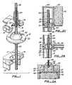
- Figure 1is an exploded perspective view of the preferred embodiment of the connecting system for an intermediate story of a building.
- Figures 2A-Cshow fragmentary, sectional views of the preferred embodiment of the connecting system for the top story, and intermediate story, and the bottom story of a building, respectively.
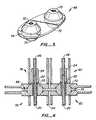
- Figure 3is a perspective view of the preferred embodiment of a double cone connector.
- Figure 4is a sectional view of the preferred embodiment of the double cone connector in an intermediate story of a building.
- a conical connector 10is attached between a tube 12 within a first module (not shown) and a tube 14 within a second module (not shown).
- a metal plate 16which defines a recess 17 to engage one end of connector 10
- a metal plate 18which defines a recess 19 to engage the other end of connector 10.
- a connecting steel rod 20extends through tube 14 and connector 10 into tube 12.
- a washer 22is placed so that the top end of rod 20 passes through washer 22 and washer 22 is flush with connector 10.
- a hexagonal coupler nut 24is threaded onto the top end of rod 20 flush against washer 22. Coupler nut 24 can be tightened to apply a predetermined amount of stress to rod 20.
- the top of connector 10has a flat surface 28, a sloping surface 30 and a flange 32 around its center.
- the bottom of connector 10is identical to the top. Lateral movement of the building causes a shearing force to be applied to the connector. Sloping surface 30 of the connector translates the shearing force into an axially directed expansion force which causes compression of tubes 12 and 14 and applies a tensile force to rods 20 and 26. Rods 20 and 26 are already highly tensioned and are able to absorb the tensile force.
- Figure 2Bshows a sectional view of connector 10 in place in an intermediate story of a building. Tubes 12 and 14 are connected to plates 16 and 18, respectively, which are in turn connected to connector 10.
- Plate 16is welded to tube 12 and is attached to a metal ceiling 36 of one module on one story of the building.
- Plate 18is welded to tube 14 and is welded to a metal floor 38 which is the floor of a module on another story of the building.
- Coupler nut 24 in each of the lower storieswill be pulled up off washer 22 due to further elongation of rods 20, 26. Coupler nut 24 will thus "float,” and the string of rods 20, 26 will effectively act as a single rod with better shock absorbing characteristics. This also virtually eliminates eccentric forces at coupler nut 24.
- Figure 2Ashows the connection of a bottom connecting rod 40 to a foundation 42.
- Rod 40extends from the bottom of the first story tube (not shown) and is threaded into an anchor cone 44.
- the upper end of anchor cone 44is shaped to fit a recess in the plate (not shown) on the bottom of the first story tube in the manner shown in Figure 1.
- Anchor cone 44is welded to a continuous metal plate 45 which is long enough to anchor a number of anchor cones 44.
- Rod 40may extend through plate 45 and be anchored by a nut 46.
- Plate 45is welded to a pair of reinforcing bars 47. Reinforcing bars 47 loop through perpendicular reinforcing bars 48 between connections to plate 45. Additional reinforcing bars 49 loop through bars 48 to provide additional structural integrity.
- Figure 2Cshows the connection of an uppermost steel rod 52 to the top of a tube 54 for the top story of a building.
- Connector 10, washer 20, and coupler nut 22are present and connected in a manner shown in Figures 1 and 2B.
- a second coupler nut 56is also threadedly attached to the end of rod 52.
- the upper end of connector 10is engaged by a disc 58 which is held in place by a sleeve 60.
- Sleeve 60is threadedly attached to a pipe sleeve 62, and a cap 64 is threadedly attached to the top of pipe sleeve 62.
- pipe sleeve 62 and cap 64are attached to enclose and protect the upper end of rod 52.
- the pipe sleeve 62 and cap 64can then be encased or embedded in a concrete roof slab 66.
- Connector 68has two conical portions 70 and 72 surrounded by a single flange 74.
- Figure 4shows connector 68 in place between adjacent modules 76, 78 on the left and 80, 82 on the right.
- the use of coupler nut 24, washer 22 and steel rods 20, 26is the same as shown in Figure 2B.
- a space 84will exist between modules 76, 78 and modules 80, 82.
- flange 74 of connector 68will transmit shear forces between modules 76, 78 and modules 80, 82. These shear forces will be transferred into tensile forces along rods 20, 26 so that substantially equal forces will be transferred by cones 70 and 72 of connector 68.
- relative movement between modules 76, 78 and modules 80, 82is greatly reduced.
- Triple or 4 cone connectorscan also be used for corner junctions of modules or at the edges of corridors, etc. Additional cones can be added by simply extending the flange so that effectively the flanges of several connectors are connected to form a single continuous flange.
- the use of the connecting system of the present inventionhas many advantages, including the ability to easily add to or disassemble (rather than demolish) existing buildings using the connecting system of the present invention.
Landscapes
- Engineering & Computer Science (AREA)
- Architecture (AREA)
- Physics & Mathematics (AREA)
- Electromagnetism (AREA)
- Civil Engineering (AREA)
- Structural Engineering (AREA)
- Joining Of Building Structures In Genera (AREA)
- Buildings Adapted To Withstand Abnormal External Influences (AREA)
- Installation Of Indoor Wiring (AREA)
Abstract
Description
- This invention relates to a modular building connecting system.
- In conventional high-rise buildings, construction tolerances are strict because the construction and placement of components of each story depend upon the shape and position of the various portions of the immediately preceding story. Field measurements are continuously required, especially for the interior structures which must rely upon actual finished, as built, conditions for their installation. Modifications to hold specified construction tolerances are usually designed into the connecting system for the skeleton of a building. For example, bolted connections in steel construction have oversized or slotted holes to accommodate dimensional errors by adjusting the placement of a nut and bolt.
- Computer analysis of the design of a building is often done to predict how the building will respond to external forces, such as earthquakes, so the building design can be modified to reduce the effect of such forces. Movements in a conventional building are difficult to predict because the locations of bolted connections can vary to give a virtually infinite number of combinations. Thus computer analysis is difficult because the values for friction and stress cannot be accurately established.
- Modular buildings, such as those disclosed in U.S. Patent No. 3,758,998, issued to Ollis et at., and U.S. Patent No. 3,925,679, issued to Berman et al., provide for the construction of the various stories of a multi-story structure at a factory and its assembly at the site. Because the fit of each story can be tested at the factory, less in-field measurements are required and changes are more conveniently implemented.
- A connecting system for a concrete building utilising a string of tensioned rods is shown in U.S. Patent No. 3,782,061 issued to Minutoli and Locke. A string of aligned rods pass through conduits in concrete building panels and are connected by nuts. The present invention provides an improved connecting system which is particularly suitable for modular steel buildings.
- Another connecting system is shown in FR-A-1455379, wherein a connector has a plate with a central bore, two sleeve members coaxial to the central bore projecting to the two sides of the plate and a plurality of peripheral engaging members fixed to the flange of the plate. Vertical tubes can be engaged with the sleeve members of the connector while horizontal members supported by a tube can be engaged with the peripheral engaging members. The tube and horizontal members are secured against the plate by a tensile cable connected to a coupler in the central bore of the connector.
- According to one aspect of the present invention there is provided a steel building construction for fastening structural members of a steel building together comprising:
a plurality of rigid, solid connectors, circular in section, each with an axial bore, a flat top surface and bottom surface perpendicular to the bore, a ring-shaped flange midway between the top surface and the bottom surface, a first sloping surface extending from the top surface toward the flange, a second sloping surface extending from the bottom surface toward the flange, wherein the circumference of the connector as defined by the sloping surfaces increases as the flange is approached, a first vertical surface extending from said first sloping surface to said flange and a second vertical surface extending from said second sloping surface to said flange, said flange having an axial dimension less than a distance from said top surface to said flange;
a plurality of rods with a threaded first end and a threaded second end, the first end of each rod passing through the bore in a connector;
a plurality of coupler nuts, each located proximate to a connector and having a threaded through bore for receiving the first end of one rod and the second end of another rod; and
a plurality of spaced structural members of a building, each structural member having a mating portion defining a recess within each of its ends shaped to couple with the portion of the connector extending outward from one of the surfaces of the flange, each said mating portion of said structural member having a sloped surface complementary to one of said connector sloped surfaces and a vertical surface joined to said mating portion sloped surface and complementary to one of said connector vertical surfaces and offset from said connector vertical surface such that a gap is defined so that said structural member sloped surface may slide along said connector sloped surface when subjected to a horizontal force, the structural members being aligned with each other, with a string of the rods extending through the structural members, coupler nuts and connectors. - In the preferred embodiment, the structural members of the building are steel modules. A number of tubes within each module are arranged vertically with rods running vertically through the tubes. The rods are connected by the connector, a washer and a coupler nut which has a threaded interior for engaging the threaded ends of two connecting rods, one of which also runs through the washer and the connector. Each tube has metal plates attached to its top and bottom through which the rods extend and each metal plate defines a recess for engaging one end of the connector.
- This connecting system acts as a shock absorber for the building. The sloping surface of the connector serves to transmit lateral shear forces applied to the building into tensile forces along the vertical steel rod, thereby increasing the buildings tolerance to external forces. The connector thus prevents shear forces from being applied to the vertical steel rods. The inclusion of a space between the recess in a structural member and the sloping surface of the connector near the flange enhances the transmission of shear forces into vertical tensile forces. The space allows the structural member to slide slightly sideways, and the sloped surface of the connector forces the structural member upward, thus changing the horizontal movement into vertical movement. The space also allows unimpeded horizontal movement and prevents sheer forces from being applied directly to the vertical rod.
- The connector can be molded with a sintered powder metal process, thereby greatly reducing the production costs associated with machined parts. The sintered metal process allows the achievement of a variety of characteristics for the connector that would otherwise be difficult to achieve (e.g., corrosion resistant metals can be readily amalgamated).
- For adjacent modules in a building, a double cone connector is used to provide a secure interconnection. The double cone connector essentially connects the flanges of two connectors to form a single flange which surrounds two conical protrusions on each side. The single flange provides continuity of lateral forces between modules by serving as the transmitter of such forces. Thus the tensile forces transmitted to the vertical steel rods in adjacent modules will be substantially the same, thereby virtually eliminating relative movements between modules. In some cases, 3, 4 or more connectors may be so combined, such as at the corner of several modules or at a corridor intersection in the building.
- The invention also allows the prestressing of each story in a simple manner by adjusting the coupler nut as each story is erected to stress the rod extending through each such story with an erection tension sufficient to hold the modules together. Progressively, at certain intermediate stories, and particularly after the top story is added, the entire string of rods can be further tensioned to achieve the desired tensile value. This will cause the coupler nut adjacent each connector in the lower stories to be pulled up off its washer and 'float' due to further elongation of the string of rods. The string of rods thus effectively becomes a single rod with correspondingly better shock absorbing characteristics.
- The tension at any connector can be specified in accordance with a computer analysis to effectively 'tune' the building to resist destructive harmonic vibrations. This is possible because the unique shape of the connector and the dimensional integrity with its mating parts in the structural members allows a precision of predictability of responses not possible with conventional building techniques.
- The modular design enhances accurate computer analysis of the building. Because the invention combines a molded connector with modular stories which can be individually adjusted by the coupler nut in the field, strict construction tolerances are dispensed with and construction costs are accordingly reduced.
- The dimensional integrity and predictable responses allowed by the MODULOC system make it ideally suited for complete design of structures by computer graphics.
- Figure 1 is an exploded perspective view of the preferred embodiment of the connecting system for an intermediate story of a building.
- Figures 2A-C show fragmentary, sectional views of the preferred embodiment of the connecting system for the top story, and intermediate story, and the bottom story of a building, respectively.
- Figure 3 is a perspective view of the preferred embodiment of a double cone connector.
- Figure 4 is a sectional view of the preferred embodiment of the double cone connector in an intermediate story of a building.
- As shown in Figure 1, a
conical connector 10 is attached between atube 12 within a first module (not shown) and atube 14 within a second module (not shown). At the end oftube 12 is attached ametal plate 16 which defines arecess 17 to engage one end ofconnector 10, and at the end oftube 14 is attached ametal plate 18 which defines arecess 19 to engage the other end ofconnector 10. A connectingsteel rod 20 extends throughtube 14 andconnector 10 intotube 12. Awasher 22 is placed so that the top end ofrod 20 passes throughwasher 22 andwasher 22 is flush withconnector 10. Ahexagonal coupler nut 24 is threaded onto the top end ofrod 20 flush againstwasher 22.Coupler nut 24 can be tightened to apply a predetermined amount of stress torod 20. After a second module (not shown) is placed on top of the first module (not shown), asecond rod 26 is extended throughtube 14 within the second module and is threaded into the upper end ofcoupler nut 24. - The top of
connector 10 has aflat surface 28, a slopingsurface 30 and aflange 32 around its center. The bottom ofconnector 10 is identical to the top. Lateral movement of the building causes a shearing force to be applied to the connector. Slopingsurface 30 of the connector translates the shearing force into an axially directed expansion force which causes compression oftubes Rods - Figure 2B shows a sectional view of
connector 10 in place in an intermediate story of a building.Tubes plates connector 10. Plate 16 is welded totube 12 and is attached to ametal ceiling 36 of one module on one story of the building.Plate 18 is welded totube 14 and is welded to a metal floor 38 which is the floor of a module on another story of the building.- After
coupler nut 24 has been threaded ontorod 20 to apply tension sufficient for erection of the building, amodule containing tube 14 and floor 38 is placed on top of themodule containing tube 12 andceiling 36.Rod 26 is then inserted intotube 14 and threadedly attached tocoupler nut 24. The process is repeated for each succeeding story. - Progressively, at desired intermediate stories, and particularly after the top story is added, the entire string of
rods Coupler nut 24 in each of the lower stories will be pulled up offwasher 22 due to further elongation ofrods Coupler nut 24 will thus "float," and the string ofrods coupler nut 24. - It can be seen that lateral shear forces will be transmitted through floor 38 and
plate 18 toconnector 10, and throughceiling 36 andplate 16 toconnector 10.Connector 10 then transfers the shear forces into axial forces along the rodstring including rods spaces 39 betweenplates connector 10 allow some horizontal movement ofplates connector 10. This horizontal movement is translated into vertical movement by the interaction of the slopingsurface 30 ofconnector 10 and the corresponding surfaces ofplates rods - Figure 2A shows the connection of a
bottom connecting rod 40 to afoundation 42.Rod 40 extends from the bottom of the first story tube (not shown) and is threaded into ananchor cone 44. The upper end ofanchor cone 44 is shaped to fit a recess in the plate (not shown) on the bottom of the first story tube in the manner shown in Figure 1.Anchor cone 44 is welded to acontinuous metal plate 45 which is long enough to anchor a number ofanchor cones 44.Rod 40 may extend throughplate 45 and be anchored by anut 46.Plate 45 is welded to a pair of reinforcing bars 47. Reinforcingbars 47 loop through perpendicular reinforcingbars 48 between connections to plate 45. Additional reinforcingbars 49 loop throughbars 48 to provide additional structural integrity. - Figure 2C shows the connection of an
uppermost steel rod 52 to the top of atube 54 for the top story of a building.Connector 10,washer 20, andcoupler nut 22 are present and connected in a manner shown in Figures 1 and 2B. Asecond coupler nut 56 is also threadedly attached to the end ofrod 52. The upper end ofconnector 10 is engaged by adisc 58 which is held in place by a sleeve 60. Sleeve 60 is threadedly attached to apipe sleeve 62, and acap 64 is threadedly attached to the top ofpipe sleeve 62. After adjustment of the tension ofrod 52 with a calibrated ram applied tocoupler nuts pipe sleeve 62 andcap 64 are attached to enclose and protect the upper end ofrod 52. Thepipe sleeve 62 andcap 64 can then be encased or embedded in aconcrete roof slab 66. - Referring to Figures 3 and 4, the preferred embodiment of a
double cone connector 68 is shown.Connector 68 has twoconical portions single flange 74. Figure 4 showsconnector 68 in place betweenadjacent modules coupler nut 24,washer 22 andsteel rods space 84 will exist betweenmodules modules flange 74 ofconnector 68 will transmit shear forces betweenmodules modules rods cones connector 68. Thus relative movement betweenmodules modules - Triple or 4 cone connectors can also be used for corner junctions of modules or at the edges of corridors, etc. Additional cones can be added by simply extending the flange so that effectively the flanges of several connectors are connected to form a single continuous flange.
- The use of the connecting system of the present invention has many advantages, including the ability to easily add to or disassemble (rather than demolish) existing buildings using the connecting system of the present invention.
- While the invention has been shown and described with reference to a preferred embodiment thereof, it will be understood by those skilled in the art that various changes in form and detail may be made therein without departing from the scope of the invention as defined in the appended claims.
Claims (15)
- A steel building construction for fastening structural members of a steel building together comprising:
a plurality of rigid, solid connectors (10, 68), circular in section, each with an axial bore, a flat top surface (28) and bottom surface perpendicular to the bore, a ring-shaped flange (32, 74) midway between the top surface and the bottom surface, a first sloping surface (30) extending from the top surface toward the flange, a second sloping surface extending from the bottom surface toward the flange, wherein the circumference of the connector as defined by the sloping surfaces increases as the flange is approached, a first vertical surface extending from said first sloping surface to said flange and a second vertical surface extending from said second sloping surface to said flange, said flange having an axial dimension less than a distance from said top surface to said flange;
a plurality of rods (20, 26, 40, 52) with a threaded first end and a threaded second end, the first end of each rod passing through the bore in a connector;
a plurality of coupler nuts (24), each located proximate to a connector and having a threaded through bore for receiving the first end of one rod and the second end of another rod; and
a plurality of spaced structural members of a building, each structural member having a mating portion (16, 18) defining a recess (17, 19) within each of its ends shaped to couple with the portion of the connector extending outward from one of the surfaces of the flange, each said mating portion of said structural member having a sloped surface complementary to one of said connector sloped surfaces and a vertical surface joined to said mating portion sloped surface and complementary to one of said connector vertical surfaces and offset from said connector vertical surface such that a gap (39) is defined so that said structural member sloped surface may slide along said connector sloped surface when subjected to a horizontal force, the structural members being aligned with each other, with a string of the rods extending through the structural members, coupler nuts and connectors. - The building construction of claim 1 further comprising a plurality of washers (22), through each of which passes a rod and each being located between a connector and a coupler nut.
- The building construction of claim 1 or claim 2 wherein the structural members include tubes (12, 14, 54) enclosing said rods.
- The building construction of claim 3 wherein each tube is connected to a module of a modular building.
- The building construction of claim 3 or claim 4 further comprising a second coupler nut (56) threadedly attached to the first end of the rod (52) extending through the top of the uppermost tube (54).
- The building construction of claim 5 further comprising a pipe sleeve (62) encasing the first end of the rod extending through the top of the uppermost tube and a cap (64) threadedly attached to the top of the pipe sleeve.
- The building construction of any one of claims 3 to 6 comprising a foundation (42) and an anchor cone (44) threadedly attached to the end of the rod (40) extending through the bottom of the lowermost tube and having an upward facing surface identical in shape to the upward half of a connector, the bottom end of said anchor cone being secured to the foundation.
- The building construction of claim 7 wherein the foundation includes a recess and further comprising a platform (45) attached to the bottom of the anchor cone (44) and a plurality of elongated members (41) attaching the platform to the bottom of the recess in the foundation.
- The building construction of any one of claims 3 to 8 further comprising a plurality of metal plates (16, 18), each metal plate attached to an end of a tube, and each metal plate defining one of the recesses (17, 19) in each tube.
- The building construction of claim 9, further comprising a plurality of metal ceilings (36), each ceiling being attached to the top end of a tube and the metal plate at the top of such tube.
- The building construction of claim 9 or claim 10 further comprising a plurality of metal floors (38), each floor being attached to the bottom end of a tube and the metal plate at the bottom of such tube.
- The building construction of any one of the preceding claims wherein at least two said connectors are joined at their flanges in the same plane, with the joined flanges forming a single continuous flange (74).
- The building construction of any one of the preceding claims wherein the coupler nuts are hexagonal nuts.
- A steel building construction for fastening structural members of a steel building together comprising:
a plurality of rigid, solid connectors (10, 68), circular in section, each with an axial bore, a flat top surface (28), and bottom surface perpendicular to the bore, a ring-shaped flange (32, 74) midway between the top surface and the bottom surface, a first sloping surface (30) extending from the top surface toward the flange, a second sloping surface extending from the bottom surface toward the flange, wherein the circumference of the connector as defined by the sloping surfaces increases as the flange is approached, a first vertical surface extending from said first sloping surface to said flange and a second vertical surface extending from said second sloping surface to said flange, said flange having an axial dimension less than a distance from said top surface to said flange;
a plurality of rods (20, 26, 40, 52) with a first threaded end and a second threaded end, the first end passing through the bore in a connector;
a plurality of cylindrical hexagonal coupler nuts (24), each located proximate to a connector and having a threaded through bore for receiving the first end of one rod and the second end of another rod;
a plurality of washers (22), through each of which passes a rod and each being located between a connector and a coupler nut;
a plurality of spaced tubes (12, 14, 54), the tubes being aligned with each other, with a string of the rods extending through the tubes, coupler nuts, connectors and washers, and with each tube forming part of a building module;
a plurality of metal plated (16, 18), each metal plate attached to an end of a tube, and each metal plate having a mating portion defining a recess (17, 19) shaped to couple with the portion of the connector extending outward from one of the surfaces of the flange, each said mating portion of said metal plate having a sloped surface complementary to one of said connector sloped surfaces and a vertical surface joined to said mating portion sloped surface and complementary to one of said connector vertical surfaces and offset from said connector vertical surface such that a gap (39) is defined so that said metal plate sloped surface may slide along said connector sloped surface when subjected to a horizontal force,
a second coupler nut (56) threadedly attached to the first end of the rod extending through the top of the uppermost tube;
a pipe sleeve (62) encasing the first end of the rod extending through the top of the uppermost tube and a cap (64) threadedly attached to the top of the pipe sleeve;
a foundation with a recess;
an anchor cone (44) threadedly attached to the end of the rod (40) extending through the bottom of the lowermost tube and having an upward facing surface identical in shape to the upward half of a connector;
a platform (45) attached to the bottom of the anchor cone;
a plurality of elongated members (47) attaching the platform to the bottom of the recess in the foundation;
a plurality of metal ceilings (36), each ceiling forming part of a building module and being attached to the top end of a tube and the metal plate at the top of such tube; and
a plurality of metal floors (38), each floor forming part of a building module and being attached to the bottom end of a tube and the metal plate and the bottom of such tube. - A steel building construction for fastening structural members of a steel building together comprising:
a plurality of rigid, solid connectors (10, 68), circular in section, each with an axial bore, a flat top surface (28) and bottom surface perpendicular to the bore, a ring-shaped flange (32, 74) midway between the top surface and the bottom surface, a first sloping surface (30) extending from the top surface toward the flange, a second sloping surface extending from the bottom surface toward the flange, wherein the circumference of the connector as defined by the sloping surfaces increases as the flange is approached, a first vertical surface extending from said first sloping surface to said flange and a second vertical surface extending from said second sloping surface to said flange, said flange having an axial dimension less than a distance from said top surface to said flange, said sloping surface being at an angle of approximately 45° relative to said flange;
a plurality of rods (20, 26, 40, 52) with a threaded first end and a threaded second end, the first end of each rod passing through the bore in a connector;
a plurality of coupler nuts (24), each located proximate to a connector and having a threaded through bore for receiving the first end of one rod and the second end of another rod; and
a plurality of spaced structural members of a building each structural member having a mating portion (16, 18) defining a recess (17, 19) within each of its ends shaped to couple with the portion of the connector extending outward from one of the surfaces of the flange each said mating portion of said structural member having a sloped surface complementary to one of said connector sloped surfaces and a vertical surface joined to said mating portion sloped surface and complementary to one of said connector vertical surfaces and offset from said connector vertical surface such that a gap (39) is defined so that said structural member sloped surface may slide along said connector sloped surface when subjected to a horizontal force, the structural members being aligned with each other, with a string of the rods extending through the structural members, coupler nuts and connectors.
Applications Claiming Priority (1)
| Application Number | Priority Date | Filing Date | Title |
|---|---|---|---|
| US06/669,154US4694621A (en) | 1984-11-07 | 1984-11-07 | Modular building connecting means |
Publications (3)
| Publication Number | Publication Date |
|---|---|
| EP0378523A1 EP0378523A1 (en) | 1990-07-25 |
| EP0378523A4 EP0378523A4 (en) | 1990-10-24 |
| EP0378523B1true EP0378523B1 (en) | 1993-03-03 |
Family
ID=24685278
Family Applications (1)
| Application Number | Title | Priority Date | Filing Date |
|---|---|---|---|
| EP87906334AExpired - LifetimeEP0378523B1 (en) | 1984-11-07 | 1987-08-31 | Modular building connecting means |
Country Status (4)
| Country | Link |
|---|---|
| US (1) | US4694621A (en) |
| EP (1) | EP0378523B1 (en) |
| AU (1) | AU609066B2 (en) |
| WO (1) | WO1989002013A1 (en) |
Cited By (4)
| Publication number | Priority date | Publication date | Assignee | Title |
|---|---|---|---|---|
| US6026618A (en)* | 1997-10-29 | 2000-02-22 | Reginald A. J. Locke | Masonry reinforcement system |
| US6871453B2 (en) | 2003-03-19 | 2005-03-29 | Reginald A. J. Locke | Modular building connector |
| DE102018131066A1 (en)* | 2018-12-05 | 2020-06-10 | Max Bögl Modul AG | Reinforcement, concrete element, module connection, module block and building |
| US11225789B2 (en) | 2018-05-17 | 2022-01-18 | Spanminx Limited | Structural module with vertical ties |
Families Citing this family (35)
| Publication number | Priority date | Publication date | Assignee | Title |
|---|---|---|---|---|
| IL91978A (en)* | 1989-10-12 | 1991-12-15 | Igal Erel | Modular prefabricated structure,the elements comprising it and a method for combining them |
| US5152118A (en)* | 1990-08-13 | 1992-10-06 | Richmond Screw Anchor Co., Inc. | Couplings for concrete reinforcement bars |
| US5826384A (en)* | 1996-11-12 | 1998-10-27 | Lucasey Manufacturing Company | Modular truss system |
| US6505450B1 (en) | 1997-10-29 | 2003-01-14 | Reginald A. J. Locke | Masonry reinforcement system |
| US6330773B1 (en) | 1999-04-16 | 2001-12-18 | Steelcase Development Corporation | Stacking bracket for partitions |
| US6151850A (en)* | 1999-04-26 | 2000-11-28 | Sorkin; Felix L. | Intermediate anchorage system utilizing splice chuck |
| US6431797B2 (en)* | 1999-06-14 | 2002-08-13 | Pyramid Retaining Walls, Llc | Masonry retainer wall system and method |
| US6632048B2 (en) | 1999-06-14 | 2003-10-14 | Pyramid Retaining Walls, Llc | Masonry retainer wall system and method |
| US6351917B1 (en) | 1999-07-30 | 2002-03-05 | Steelcase Development Corporation | Stacking connector for partitions |
| ES2285877B1 (en)* | 2004-08-12 | 2008-10-16 | Compact-Habit, S.L. | STRUCTURAL SYSTEM FOR BUILDINGS. |
| ES2284306B1 (en)* | 2005-03-03 | 2008-09-16 | Compact-Habit, S.L. | MODULAR CONSTRUCTION SYSTEM. |
| ES2303457B1 (en)* | 2006-12-01 | 2009-08-03 | Habidite, S.A. | CONSTRUCTION SYSTEM. |
| US8272806B2 (en)* | 2008-01-22 | 2012-09-25 | Ford Contracting, Inc. | Panel connector |
| WO2010107352A1 (en)* | 2009-03-19 | 2010-09-23 | Telefonaktiebolaget L M Ericsson (Publ) | Tubular telecom tower structure |
| FI20090170L (en)* | 2009-04-28 | 2010-10-29 | Shippax Ltd Oy | Arrangement and method for attaching prefabricated load-bearing room units to each other |
| WO2010151539A1 (en) | 2009-06-22 | 2010-12-29 | Barnet Liberman | Modular building system for constructing multi-story buildings |
| US20110232543A1 (en)* | 2010-03-24 | 2011-09-29 | Paramount Structures Inc. | Attachment mechanism for blast resistant modular buildings |
| JP5707418B2 (en)* | 2010-11-24 | 2015-04-30 | ▲勧▼ 渡辺 | Concatenation method for container-type unit construction |
| ITMI20112372A1 (en)* | 2011-12-23 | 2013-06-24 | D L C S R L | PREFABRICATED STRUCTURE IN CONCRETE FOR CIVIL BUILDINGS ASSEMBLED BY DRY |
| CN102653953B (en)* | 2012-03-15 | 2013-11-20 | 北京市轨道交通建设管理有限公司 | Inner tensioning pre-stressed concrete single-layer variable section plate box-type structure |
| CN102653957B (en)* | 2012-03-15 | 2013-09-11 | 中国建筑科学研究院 | Inner tensioning pre-stressed concrete double-layer T-shaped framework box-type structure |
| CN102653954B (en)* | 2012-03-15 | 2013-09-11 | 北京市轨道交通建设管理有限公司 | Inner tensioning pre-stressed concrete double-layer variable section plate box-type structure |
| CN102653955B (en)* | 2012-03-15 | 2013-11-20 | 北京市轨道交通建设管理有限公司 | Inner tension prestressed concrete single-layer T-shaped frame box structure |
| CN102653958B (en)* | 2012-03-15 | 2013-09-11 | 北京市轨道交通建设管理有限公司 | Inner tensioning pre-stressed concrete double-layer I-shaped framework box-type structure |
| WO2014074508A1 (en)* | 2012-11-06 | 2014-05-15 | FC+Skanska Modular, LLC | Modular building unit connection system |
| EP3037608A1 (en)* | 2014-12-24 | 2016-06-29 | Rv Lizenz AG | Installation system for modular industrial installations |
| WO2016118430A1 (en)* | 2015-01-24 | 2016-07-28 | Su Hao | Seismic-proof connectors to protect buildings and bridges from earthquake hazards and enable fast construction |
| US10024047B2 (en)* | 2015-08-17 | 2018-07-17 | Tindall Corporation | Method and apparatus for constructing a concrete structure |
| SG10201510782WA (en)* | 2015-12-30 | 2017-07-28 | Dragages Singapore Pte Ltd | Apparatus For Connecting Prefinished Prefabricated Volumetric Construction Units |
| CA3052830A1 (en) | 2017-02-15 | 2018-08-23 | Tindall Corporation | Methods and apparatuses for constructing a concrete structure |
| EP3502368B1 (en)* | 2017-12-21 | 2023-12-06 | Tomba Enterprises Pty Ltd | Structural connector |
| US10920412B2 (en)* | 2018-12-29 | 2021-02-16 | Hall Labs Llc | Modular building unit and system |
| US11951652B2 (en) | 2020-01-21 | 2024-04-09 | Tindall Corporation | Grout vacuum systems and methods |
| AU2021414233A1 (en) | 2020-12-31 | 2023-07-20 | Mitek Holdings, Inc. | Rapid assembly construction modules and methods for use |
| CN113513087B (en)* | 2021-08-03 | 2025-01-24 | 上海鹄鸫重工股份有限公司 | Eight-sided end plate assembly, structural unit and assembly structure thereof |
Family Cites Families (15)
| Publication number | Priority date | Publication date | Assignee | Title |
|---|---|---|---|---|
| US537491A (en)* | 1895-04-16 | Pitman-box | ||
| US1012422A (en)* | 1909-04-06 | 1911-12-19 | Benjamin Franklin Orewiler | Hose-supporter clasp. |
| US1188485A (en)* | 1910-09-03 | 1916-06-27 | Underpinning & Foundation Company | Tube joint and guide. |
| US1012423A (en)* | 1910-12-27 | 1911-12-19 | William J W Orr | Sectional concrete telegraph-pole. |
| US1786631A (en)* | 1928-04-25 | 1930-12-30 | Stephen W Borden | Supporting pole for electrical conductors |
| FR1455379A (en)* | 1965-09-01 | 1966-04-01 | Vallourec | Pretended tubular frame |
| GB1311876A (en)* | 1969-06-20 | 1973-03-28 | Timber Research Dev Ass | Multistorey building block |
| GB1268995A (en)* | 1970-07-23 | 1972-03-29 | Sture Magne Martinsson | A joint arrangement for concrete piles |
| US3782061A (en)* | 1972-03-23 | 1974-01-01 | A Minutoli | Concrete building construction with improved post tensioning means |
| US3999355A (en)* | 1974-01-31 | 1976-12-28 | Credelca Ag | Method of constructing a transportable prefabricated room element |
| US3965627A (en)* | 1974-07-15 | 1976-06-29 | Miroslav Fencl | Interconnection of modular structures |
| US4081936A (en)* | 1976-11-24 | 1978-04-04 | The Flexicore Co., Inc. | Structural framework with improved connector |
| SU633997A1 (en)* | 1977-06-09 | 1978-11-25 | Ордена Трудового Красного Знамени Центральный Научно-Исследовательский Институт Им. В.А.Кучеренко Госстроя Ссср | Device for joining panels |
| US4161089A (en)* | 1977-12-14 | 1979-07-17 | Omansky Martin B | Modular building structure system |
| US4294051A (en)* | 1979-05-21 | 1981-10-13 | Hughes Jr William J | Modular building system |
- 1984
- 1984-11-07USUS06/669,154patent/US4694621A/ennot_activeExpired - Lifetime
- 1987
- 1987-08-31AUAU80315/87Apatent/AU609066B2/ennot_activeCeased
- 1987-08-31EPEP87906334Apatent/EP0378523B1/ennot_activeExpired - Lifetime
- 1987-08-31WOPCT/US1987/002178patent/WO1989002013A1/enactiveIP Right Grant
Cited By (4)
| Publication number | Priority date | Publication date | Assignee | Title |
|---|---|---|---|---|
| US6026618A (en)* | 1997-10-29 | 2000-02-22 | Reginald A. J. Locke | Masonry reinforcement system |
| US6871453B2 (en) | 2003-03-19 | 2005-03-29 | Reginald A. J. Locke | Modular building connector |
| US11225789B2 (en) | 2018-05-17 | 2022-01-18 | Spanminx Limited | Structural module with vertical ties |
| DE102018131066A1 (en)* | 2018-12-05 | 2020-06-10 | Max Bögl Modul AG | Reinforcement, concrete element, module connection, module block and building |
Also Published As
| Publication number | Publication date |
|---|---|
| AU8031587A (en) | 1989-03-31 |
| AU609066B2 (en) | 1991-04-26 |
| EP0378523A4 (en) | 1990-10-24 |
| WO1989002013A1 (en) | 1989-03-09 |
| US4694621A (en) | 1987-09-22 |
| EP0378523A1 (en) | 1990-07-25 |
Similar Documents
| Publication | Publication Date | Title |
|---|---|---|
| EP0378523B1 (en) | Modular building connecting means | |
| US5561956A (en) | Concrete elements and connectors therefor | |
| US6871453B2 (en) | Modular building connector | |
| US6550200B1 (en) | Anchor interconnect device | |
| KR20120120233A (en) | Panelized structural system for building construction | |
| US7007431B2 (en) | Multi-story building and method for construction thereof | |
| US20170009477A1 (en) | Retrofitting structure for existing building | |
| AU2022287672A1 (en) | Connection system | |
| KR20190072336A (en) | Building Core System using Precast Concrete Panel with Column in the Center | |
| JPH03501984A (en) | Tightening structure of steel buildings | |
| GB1572843A (en) | Building and/or a building method using columns of cruciform section and beams | |
| JP2001254445A (en) | Upper and lower joint structure of prefabricated building | |
| JPS602462B2 (en) | Precast concrete shear wall assembly method | |
| JP3742703B2 (en) | Reinforcement structure for bolt-shaped fixtures and building and structure reinforcement structures using the same | |
| CN223048319U (en) | Reinforcing steel bar mechanical connection structure and combined structure of core tube and peripheral floor slab | |
| CN219060368U (en) | Novel assembled building light steel joist connection structure | |
| JP7572180B2 (en) | Reinforced concrete structure | |
| JPS6351215B2 (en) | ||
| KR200271767Y1 (en) | Concrete beam | |
| WO2024058728A1 (en) | Modular building connection system | |
| WO2001075241A1 (en) | Structure | |
| KR20250103949A (en) | Connection structure of modular unit using multi-connectors | |
| WO2024224160A1 (en) | 3d connector for modular construction of multi-story buildings | |
| JPH0130482Y2 (en) | ||
| JPH09221829A (en) | Vibration control system for reinforced concrete structures |
Legal Events
| Date | Code | Title | Description |
|---|---|---|---|
| PUAI | Public reference made under article 153(3) epc to a published international application that has entered the european phase | Free format text:ORIGINAL CODE: 0009012 | |
| 17P | Request for examination filed | Effective date:19900226 | |
| AK | Designated contracting states | Kind code of ref document:A1 Designated state(s):AT BE CH DE FR GB IT LI LU NL SE | |
| A4 | Supplementary search report drawn up and despatched | Effective date:19900905 | |
| AK | Designated contracting states | Kind code of ref document:A4 Designated state(s):AT BE CH DE FR GB IT LI LU NL SE | |
| RBV | Designated contracting states (corrected) | Designated state(s):DE FR GB IT NL | |
| 17Q | First examination report despatched | Effective date:19920109 | |
| GRAA | (expected) grant | Free format text:ORIGINAL CODE: 0009210 | |
| AK | Designated contracting states | Kind code of ref document:B1 Designated state(s):DE FR GB IT NL | |
| RBV | Designated contracting states (corrected) | Designated state(s):GB | |
| PLBE | No opposition filed within time limit | Free format text:ORIGINAL CODE: 0009261 | |
| STAA | Information on the status of an ep patent application or granted ep patent | Free format text:STATUS: NO OPPOSITION FILED WITHIN TIME LIMIT | |
| 26N | No opposition filed | ||
| REG | Reference to a national code | Ref country code:GB Ref legal event code:IF02 | |
| PGFP | Annual fee paid to national office [announced via postgrant information from national office to epo] | Ref country code:GB Payment date:20040825 Year of fee payment:18 | |
| PG25 | Lapsed in a contracting state [announced via postgrant information from national office to epo] | Ref country code:GB Free format text:LAPSE BECAUSE OF NON-PAYMENT OF DUE FEES Effective date:20050831 | |
| GBPC | Gb: european patent ceased through non-payment of renewal fee | Effective date:20050831 |