EP0377055B1 - Electro-optical arrangement for the remote control of electronic apparatuses - Google Patents
Electro-optical arrangement for the remote control of electronic apparatusesDownload PDFInfo
- Publication number
- EP0377055B1 EP0377055B1EP88121922AEP88121922AEP0377055B1EP 0377055 B1EP0377055 B1EP 0377055B1EP 88121922 AEP88121922 AEP 88121922AEP 88121922 AEP88121922 AEP 88121922AEP 0377055 B1EP0377055 B1EP 0377055B1
- Authority
- EP
- European Patent Office
- Prior art keywords
- radiation
- optical axis
- electrooptical
- radiation sources
- sources
- Prior art date
- Legal status (The legal status is an assumption and is not a legal conclusion. Google has not performed a legal analysis and makes no representation as to the accuracy of the status listed.)
- Expired - Lifetime
Links
Images

Classifications
- G—PHYSICS
- G06—COMPUTING OR CALCULATING; COUNTING
- G06F—ELECTRIC DIGITAL DATA PROCESSING
- G06F3/00—Input arrangements for transferring data to be processed into a form capable of being handled by the computer; Output arrangements for transferring data from processing unit to output unit, e.g. interface arrangements
- G06F3/01—Input arrangements or combined input and output arrangements for interaction between user and computer
- G06F3/03—Arrangements for converting the position or the displacement of a member into a coded form
- G06F3/0304—Detection arrangements using opto-electronic means
- G06F3/0308—Detection arrangements using opto-electronic means comprising a plurality of distinctive and separately oriented light emitters or reflectors associated to the pointing device, e.g. remote cursor controller with distinct and separately oriented LEDs at the tip whose radiations are captured by a photo-detector associated to the screen
- G—PHYSICS
- G06—COMPUTING OR CALCULATING; COUNTING
- G06F—ELECTRIC DIGITAL DATA PROCESSING
- G06F3/00—Input arrangements for transferring data to be processed into a form capable of being handled by the computer; Output arrangements for transferring data from processing unit to output unit, e.g. interface arrangements
- G06F3/01—Input arrangements or combined input and output arrangements for interaction between user and computer
- G06F3/03—Arrangements for converting the position or the displacement of a member into a coded form
- G06F3/033—Pointing devices displaced or positioned by the user, e.g. mice, trackballs, pens or joysticks; Accessories therefor
- G06F3/0346—Pointing devices displaced or positioned by the user, e.g. mice, trackballs, pens or joysticks; Accessories therefor with detection of the device orientation or free movement in a 3D space, e.g. 3D mice, 6-DOF [six degrees of freedom] pointers using gyroscopes, accelerometers or tilt-sensors
- G—PHYSICS
- G08—SIGNALLING
- G08C—TRANSMISSION SYSTEMS FOR MEASURED VALUES, CONTROL OR SIMILAR SIGNALS
- G08C23/00—Non-electrical signal transmission systems, e.g. optical systems
- G08C23/04—Non-electrical signal transmission systems, e.g. optical systems using light waves, e.g. infrared
- G—PHYSICS
- G08—SIGNALLING
- G08C—TRANSMISSION SYSTEMS FOR MEASURED VALUES, CONTROL OR SIMILAR SIGNALS
- G08C2201/00—Transmission systems of control signals via wireless link
- G08C2201/30—User interface
- G08C2201/32—Remote control based on movements, attitude of remote control device
Definitions
- Electronic devices that are remotely controllableare becoming increasingly common, especially when it comes to consumer electronics devices. Above all, this includes television sets, video recorders, phono devices and the like. It is similar when home computers, garage doors, shutters and the like are to be operated. Control signals for the device or devices to be controlled are triggered depending on the buttons to be operated by the user. A correspondingly modulated or coded ultrasound or infrared signal serves as the transmission medium.
- US Pat. No. 4,745,402describes an electro-optical arrangement for remote control of electronic devices which uses the spatial orientation of the remote control transmitter to the remote control receiver to control the functions provided.
- the direction information of the position-dependent controlis determined for each direction by three infrared transmit diodes, which are controlled with square-wave signals of different phase positions.
- the three radiation diagramsare assigned three overlapping angular ranges in the respective spatial plane.
- a single, resulting signalis formed from the three signals different in phase, the phase position of which deviates from a reference phase depending on the angular position of the remote control transmitter.
- the associated alignment angleis determined from the measured phase difference.
- the three infrared signal sourcesare supplemented to form a diode array made up of at least eight infrared diodes, the radiation diagrams of the diodes being as identical and rotationally symmetrical as possible, but with their axes aimed in different spatial directions.
- the reference phaseis defined by means of a phase locking loop which is synchronized by means of a synchronization sequence from the remote control transmitter.
- the position control according to the inventionconsists in evaluating the relative position of the remote control transmitter with respect to the respective connecting line between remote control transmitter and electronic device by means of a suitable electro-optical arrangement.
- reference signalsare generated in the electronic device by means of an evaluation circuit which correspond to the tilt angle in the respective direction.
- the evaluation of the respective tilt anglealso enables continuous control, which is desirable, for example, when adjusting the volume; but also when using the remote control transmitter, for example in a home computer, graphic representations on the Screen should be generated.
- the combined evaluation of the two tilt directionsallows continuous movement control in every direction on the screen.
- the basic idea of the electro-optical arrangement according to the inventionis that three radiation sources, the radiation diagrams of which differ from one another and with respect to the three spatial axes, form the part of the electro-optical arrangement on the transmitter side and that different radiation intensities are received on the receiver side, depending on the tilting direction of the remote control transmitter whose relation to each other are evaluated for position determination.
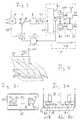
- FIG. 1ashows a schematic top view of the three radiation diagrams of the three radiation sources q1, q2, q3 present in the remote control transmitter g.
- the three other partial figures b), c), d) of FIG. 1show the associated schematic side views of these three radiation diagrams. They are also shown in dashed lines, but the essential part is highlighted by a solid line.
- the control of the three radiation sources q1, q2, q3takes place by means of the control device st, which, for example, controls the three radiation sources in time-division multiplex mode in pulses with a short pause in succession and inserts an extended pause as an identification signal after every third pulse.
- the three radiation sourcesare located on the end face of the remote control housing gg, to the longitudinal axis of the housing the three optical axes o1, o2, o3 of the three radiation sources are aligned in parallel.
- the remote control transmitter gcan of course, as with conventional remote control transmitters, additionally contain a keyboard coding circuit which generates a coded signal via further electronic devices which is emitted via an infrared light-emitting diode.
- the third radiation source q3would also be used because of its uniform Radiation pattern. Menu operation can also be started and the selected operator command triggered using the keypad or special keys.
- the radiation diagram of the first radiation source q1has a strongly changing intensity profile in the horizontal reference plane in the direction of its optical axis o1, in the illustrated first angular range w1. This is not the case with the radiation diagrams of the second and third radiation sources q2, q3. In the top view, these each have a flat intensity profile in the angular range w1. It should be noted that the radiation diagrams are each shown as a projection. 1, the radiation diagrams at the intersection with their optical axes all have approximately the same intensity value. However, this is not a requirement of the invention.
- Figures 1b), c) and d)show the vertical projection of the radiation diagrams of the three radiation sources q1, q3, q2.
- the reference plane for the second angular range w2is the vertical plane in which the respective optical axis o1, o2, o3 lies.
- the radiation diagrams of the first and third radiation sources q1, q3have a flat intensity curve in the second angular range w2, while the second radiation source q2 contains a strongly changing intensity curve. If the second radiation source q2 is tilted up or down, its intensity increases or decreases.
- the radiation detector pserves to receive the radiation emanating from the three radiation sources q1, q2, q3 together.
- the radiation detector p on the front of the electronic deviceeg contains e.g. an infrared receiver diode, the output signals of which are amplified by means of the controllable amplifier v and are coupled to the decoding circuit cd via the filter f for interference suppression. This separates, for example, the three pulses received in multiplex mode and forms the three component signals k1, k2, k3, which correspond to the respectively received signal from the first, second and third radiation sources q1, q2, q3.
- An evaluation circuit awis fed with these three component signals k1 k2, k3, which generates reference signals z1, z2, which correspond to the tilt angle in the respective reference plane.
- the evaluation circuit aw shown in FIG. 2is particularly simple, since it forms the first difference signal d1 from the first and third component signals k3 by means of the first subrahier sb1 and the second difference signal from the second and third component signals k2, k3 by means of the second subrahier sb2 d2.
- the strongly angle-dependent intensity profile of the radiation diagram of the first and second radiation sources q1, q2becomes relative angle-independent radiation diagram of the third radiation source q3 compared. Since the absolute intensity is very strongly dependent on the distance, a subsequent normalization of the two difference signals d1, d2 by means of the first and the second nomination circuit g1, g2 is necessary, which the first and the second difference signal d1, d2 each by the value of the third component signal k3 divided and thus forms the first or the second reference signal z1, z2 as the output signal. The respective value of these two reference signals is thus approximately proportional to the respective tilt angle.
- the controllable amplifier valso partially compensates for the distance-dependent change in intensity. Its control signal is derived from the third component signal k3, which is low-pass filtered via the control stage cs.
- the controllable amplifier vis required in particular if the decoding circuit cd and the evaluation circuit aw are designed as digital circuits. Without the controllable amplifier v, the resolution of the analog-to-digital converter c1 could become too imprecise due to the small signal amplitude if only a few quantization stages are involved.
- the control input of the controllable amplifier vis controlled in digital processing via the digital-to-analog converter c2.
- the analog-digital converter c1also allows the decoding circuit cd and the evaluation circuit aw in the electronic devices to be operated remotely can be realized by means of a microprocessor P which is loaded with a program which has the same effect as the decoding circuit cd and the evaluation circuit aw.
- a microprocessor already present in the electronic device egcan then be used for the position detection, since the processes to be calculated run slowly and can therefore be easily inserted into another program.
- the radiation diagrams shown in FIG. 1can be generated in many ways. It is particularly simple if at least the first and second radiation sources q1, q2 are linear or flat and each have an aperture b1, b2 in the direction of the optical axis o1, o2, some distance from their radiating surface, which has the associated one Radiation source q1, q2 partially covered.
- the effective diaphragm edge in the first and in the second radiation source q1, q2must have a spatial component perpendicular to the direction of the first and the second reference plane.
- the first or the second reference planeis determined by its respective optical axis o1, o2 and the respective direction in which the possible tilt angle, namely the first or second angular range w1, w2, lies. It is also necessary that the radiation diagram of the first and second radiation sources q1, q2, measured without an aperture, has a symmetrical, as flat as possible intensity profile in the first and in the second angular range w1, w2.
- the surface design of the three radiation sourcesis pretty minor. These can be matt surfaces, i.e. pure cosine emitters, but also surfaces that bundle the beams in the direction of the optical axis in order to push the remote control limit beyond the higher intensity.
- FIG. 3ashows the end face of the remote control transmitter g, which in the optical window often contains the three radiation sources q1, q2, q3, each with a square radiation area.
- the left half of the first radiation source q1is covered by the first aperture b1 and the lower half is covered by the aperture b2 in the second radiation source q2.
- the degree of coverage of the first radiation source q1thus changes, while the degree of coverage of the second radiation source q2 is not changed.
- the adjacent Fig. 3bshows the front of this Remote control g in supervision.
- the first radiation source q1covers the left half through the first aperture b1, while the aperture edge of the second aperture b2 extends in front of the entire second radiation source q2.
- 3bshows the distance at which the two diaphragms b1, b2 are located in front of the respective radiation surfaces.
- the choice of the respective distanceresults from the required angular sensitivity of the remote control transmitter.
- the square design of the radiation surfacesis particularly advantageous because they allow the horizontal and vertical tilting directions to be separated in the simplest way, provided that the square edges and the diaphragm edges are aligned in this direction.
- the diaphragmsshows another design of the diaphragms, namely in the form of lamella diaphragms 11 which are inclined by the fixed angle w3 with respect to the optical axis oi.
- the respective angle of inclination w3lies outside the first or second angular range w1, w2, so that the maximum passage and blocking direction of these lamellae 11 are also outside the associated first or second angular range w1, w2.
- the combination of the lamella diaphragmsis possible with any linear or flat radiation surfaces qi, but particularly advantageously again with square radiation surfaces.
- the advantage of lamella covers 11is that the angular sensitivity to single diaphragms is significantly increased. The closer the distance between the parallel lamella diaphragms 11, the greater the sensitivity with the same lamella shape.
- optical meanswhich are either located in the surface of the respective radiation sources or in front of them.
- the usual optical basic shapessuch as prisms or lenses are addressed as optical means, wherein the lenses can be cylindrical, spherical or aspherical.
- a combination of several basic shapes or a fine structuresuch as is possible with the Fresnel lens.
- a simple prism that tilts the radiation lobe out of the original optical axisis sufficient so that the required rising / falling intensity curve is present in the required angular range w1 or w2 around the original optical axis.
- a correspondingly inclined installation of the radiation sourcewould have the same effect.
Landscapes
- Engineering & Computer Science (AREA)
- General Engineering & Computer Science (AREA)
- Theoretical Computer Science (AREA)
- Physics & Mathematics (AREA)
- General Physics & Mathematics (AREA)
- Human Computer Interaction (AREA)
- Optical Communication System (AREA)
- Selective Calling Equipment (AREA)
Description
Translated fromGermanElektronische Geräte, die fernsteuerbar sind, finden zunehmend Verbreitung, besonders wenn es sich dabei um Geräte der Unterhaltungselektronik handelt. Hierunter zählen vor allen Dingen Fernsehgeräte, Videorecorder, Phonogeräte und dergleichen mehr. Ähnlich ist es, wenn Heimcomputer, Garagentore, Rolläden und ähnliches bedient werden sollen. Dabei werden in Abhängigkeit von vom Benutzer zu betätigenden Tasten Steuersignalen für das bzw. die zu steuernden Geräte ausgelöst. Als Übertragungsmedium dient ein entsprechend moduliertes oder codiertes Ultraschall- oder Infrarot-Signal.Electronic devices that are remotely controllable are becoming increasingly common, especially when it comes to consumer electronics devices. Above all, this includes television sets, video recorders, phono devices and the like. It is similar when home computers, garage doors, shutters and the like are to be operated. Control signals for the device or devices to be controlled are triggered depending on the buttons to be operated by the user. A correspondingly modulated or coded ultrasound or infrared signal serves as the transmission medium.
Bei der Vielzahl der bereits an einem einzigen Gerät zu steuernden Funktionen, z.B. bei einem Fernsehgerät das außer den zu empfangenden Programmen noch Teletext empfängt und zusätzlich an einen Videorecorder angeschlossen ist, ist eine entsprechende Vielzahl von Steuerbefehlen erforderlich, denen eine entsprechende Anzahl von Tasten des Fernsteuergebers entspricht. Eine Reduktion ist durch Mehrfachbelegung der Tasten möglich, wobei die Bedienung aber unübersichtlich wird. Eine drastische Reduzierung der Tastenanzahl ist auf diese Weise nicht möglich.With the multitude of functions that can already be controlled on a single device, e.g. In the case of a television set which receives teletext in addition to the programs to be received and is additionally connected to a video recorder, a corresponding number of control commands are required, to which a corresponding number of buttons on the remote control transmitter correspond. A reduction is possible by multiple assignment of the keys, but the operation is confusing. A drastic reduction in the number of keys is not possible in this way.
Einen Ausweg aus dieser Situation bietet der sogenannte interaktive Betrieb mit dem zu steuernden Gerät, der z. B. bei Rechnern üblich ist, wo über den Bildschirm dem Bedienenden ein "Menü" aus einer Vielzahl von möglichen Steuerungs- oder Bedienungsbefehlen angeboten wird, aus denen der Bedienende dann über das Tastenfeld oder mit einer sogenannten "Maus" den gewünschten auswählt.A way out of this situation is the so-called interactive operation with the device to be controlled, which, for. B. is common in computers where on the screen Operators are offered a "menu" from a large number of possible control or operating commands, from which the operator then selects the desired one via the keypad or with a so-called "mouse".
Dabei bestimmt die jeweilige Position der auf dem Tisch bewegten Maus die Position eines Cursers (=Markierungsfleck) auf dem Bildschirm.The respective position of the mouse moved on the table determines the position of a cursor (= marking spot) on the screen.
In US-A 4 745 402 ist eine elektrooptische Anordnung zur Fernbedienung elektronischer Geräte beschrieben, die zur Steuerung der vorgesehenen Funktionen die räumliche Ausrichtung des Fernbedienungsgebers zum Fernbedienungsempfänger verwendet. Die Richtungsinformation der positionsabhängigen Steuerung wird für jede Richtung durch drei Infrarot-Sendedioden bestimmt, die mit Rechtecksignalen unterschiedlicher Phasenlage angesteuert sind. Den drei Strahlungsdiagrammen sind in der jeweiligen Raumebene drei überlappende Winkelbereiche zugeordnet. Empfangsseitig wird aus den drei in der Phase unterschiedlichen Signalen ein einziges, resultierendes Signal gebildet, dessen Phasenlage je nach der Winkelstellung des Fernbedienungsgebers von einer Referenzphase abweicht. Aus der gemessenen Phasendifferenz wird der zugehörige Ausrichtungswinkel bestimmt. Damit die Messung in zwei Raumebenen erfolgen kann, werden die drei Infrarotsignalquellen zu einem Diodenfeld aus mindestens acht Infrarotdioden ergänzt, wobei die Strahlungsdiagramme der Dioden möglichst gleich und rotationssymmetrisch sind, ihre Achsen aber in unterschiedliche Raumrichtungen zielen. Die Referenzphase wird mittels einer Phasenverriegelungsschleife definiert, die mittels einer Synchronisationsabfolge von Fernbedienungsgeber synchronisiert wird.US Pat. No. 4,745,402 describes an electro-optical arrangement for remote control of electronic devices which uses the spatial orientation of the remote control transmitter to the remote control receiver to control the functions provided. The direction information of the position-dependent control is determined for each direction by three infrared transmit diodes, which are controlled with square-wave signals of different phase positions. The three radiation diagrams are assigned three overlapping angular ranges in the respective spatial plane. At the receiving end, a single, resulting signal is formed from the three signals different in phase, the phase position of which deviates from a reference phase depending on the angular position of the remote control transmitter. The associated alignment angle is determined from the measured phase difference. So that the measurement can take place in two spatial levels, the three infrared signal sources are supplemented to form a diode array made up of at least eight infrared diodes, the radiation diagrams of the diodes being as identical and rotationally symmetrical as possible, but with their axes aimed in different spatial directions. The reference phase is defined by means of a phase locking loop which is synchronized by means of a synchronization sequence from the remote control transmitter.
Es ist daher Aufgabe der in den Ansprüchen gekennzeichneten Erfindung für elektronische Geräte eine einfache elektrooptische Anordnung anzugeben, die auch bei fernbedienten elektronischen Geräten eine derartige Positionssteuerung ermöglicht, um die erforderliche Anzahl von Tasten zu reduzieren.It is therefore an object of the invention characterized in the claims for electronic devices to provide a simple electro-optical arrangement which also enables such position control in the case of remote-controlled electronic devices in order to reduce the required number of buttons.
Die Positionssteuerung nach der Erfindung besteht darin, mittels einer geeigneten elektrooptischen Anordnung die relative Position des Fernbedienungsgebers bezüglich der jeweiligen Verbindungslinie zwischen Fernbedienungsgeber und elektronischem Gerät auszuwerten. Durch Kippen des Fernbedienungsgebers, z.B. in vertikaler oder in horizontaler Richtung, werden im elektronischen Gerät mittels einer Auswerteschaltung Bezugssignale erzeugt, die dem Kippwinkel in der jeweiligen Richtung entsprechen. Von besonderem Vorteil ist dabei, daß die Auswertung des jeweiligen Kippwinkels auch eine kontinuierliche Steuerung ermöglicht, die beispielsweise bei der Lautstärkeeinstellung erwünscht ist; aber auch dann, wenn mittels des Fernbedienungsgebers, z.B. bei einem Heimrechner, graphische Darstellungen auf dem Bildschirm erzeugt werden sollen. Die kombinierte Auswertung der beiden Kipprichtungen erlaubt nämlich eine kontinuierliche Bewegungssteuerung in jeder Richtung auf dem Bildschirm.The position control according to the invention consists in evaluating the relative position of the remote control transmitter with respect to the respective connecting line between remote control transmitter and electronic device by means of a suitable electro-optical arrangement. By tilting the remote control transmitter, for example in the vertical or in the horizontal direction, reference signals are generated in the electronic device by means of an evaluation circuit which correspond to the tilt angle in the respective direction. It is particularly advantageous that the evaluation of the respective tilt angle also enables continuous control, which is desirable, for example, when adjusting the volume; but also when using the remote control transmitter, for example in a home computer, graphic representations on the Screen should be generated. The combined evaluation of the two tilt directions allows continuous movement control in every direction on the screen.
Der Grundgedanke der elektrooptischen Anordnung nach der Erfindung besteht darin, daß drei Strahlungsquellen, deren Strahlungsdiagramme untereinander und bezüglich der drei Raumachsen unterschiedlich sind, den geberseitigen Anteil der elektrooptischen Anordnung bilden und daß dadurch auf der Empfängerseite, je nach Kipprichtung des Fernbedienungsgebers, unterschiedliche Strahlungsintensitäten empfangen werden, deren Relation zueinander zur Positionsbestimmung ausgewertet werden.The basic idea of the electro-optical arrangement according to the invention is that three radiation sources, the radiation diagrams of which differ from one another and with respect to the three spatial axes, form the part of the electro-optical arrangement on the transmitter side and that different radiation intensities are received on the receiver side, depending on the tilting direction of the remote control transmitter whose relation to each other are evaluated for position determination.
Die Erfindung wird nun anhand der Figuren der Zeichnungen näher erläutert.
- Fig. 1 zeigt stark schematisiert, das der Erfindung zugrundliegende Prinzip anhand der Strahlungsdiagramme dreier Strahlungsquellen in einem Fernbedienungsgeber,
- Fig. 2 zeigt stark schematisiert die Empfängerseite der elektrooptischen Anordnung mit einem als Blockschaltbild ausgeführten Ausführungsbeispiel der Empfangsschaltung,
- Fig. 3a und Fig. 3b zeigen schematisiert eine Detailansicht einer besonders vorteilhaften senderseitigen elektrooptischen Anordnung.
- Fig. 4 zeigt als schematisches Beispiel eine Strahlungsquelle mit Lamellenblende.
- 1 shows, in a highly schematic manner, the principle on which the invention is based on the radiation diagrams of three radiation sources in a remote control transmitter,
- 2 shows a highly schematic view of the receiver side of the electro-optical arrangement with an exemplary embodiment of the receiving circuit designed as a block diagram,
- 3a and 3b schematically show a detailed view of a particularly advantageous transmitter-side electro-optical arrangement.
- FIG. 4 shows a radiation source with a lamella diaphragm as a schematic example.
Die Fig. 1a zeigt in schematischer Aufsicht die drei Strahlungsdiagramme der drei im Fernbedienungsgeber g vorhandenen Strahlungsquellen q1, q2, q3. Die drei anderen Teilfiguren b), c), d) der Fig. 1 zeigen die zugehörigen schematischen Seitenansichten dieser drei Strahlungsdiagramme. Sie sind ebenfalls gestrichelt dargestellt, der wesentliche Teil ist dagegen mittels einer durchgezogenen Linie hervorgehoben.1a shows a schematic top view of the three radiation diagrams of the three radiation sources q1, q2, q3 present in the remote control transmitter g. The three other partial figures b), c), d) of FIG. 1 show the associated schematic side views of these three radiation diagrams. They are also shown in dashed lines, but the essential part is highlighted by a solid line.
Die Ansteuerung der drei Strahlungsquellen q1, q2, q3 erfolgt mittels der Steuereinrichtung st, die beispielsweise die drei Strahlungsquellen im Zeitmultiplexbetrieb impulsweise mit einer kurzen Zwischenpause nacheinander ansteuert und als Kennungssignal nach jedem dritten Impuls eine verlängerte Pause einfügt. Die drei Strahlungsquellen befinden sich an der Stirnseite des Fernbedienungsgehäuses gg, zu dessen längsliegender Gehäuseachse die drei optischen Achsen o1, o2, o3 der drei Strahlungsquellen parallel ausgerichtet sind.The control of the three radiation sources q1, q2, q3 takes place by means of the control device st, which, for example, controls the three radiation sources in time-division multiplex mode in pulses with a short pause in succession and inserts an extended pause as an identification signal after every third pulse. The three radiation sources are located on the end face of the remote control housing gg, to the longitudinal axis of the housing the three optical axes o1, o2, o3 of the three radiation sources are aligned in parallel.
Der Fernbedienungsgeber g kann selbstverständlich wie bei üblichen Fernbedienungsgebern zusätzlich eine Tastatur-Codierschaltung enthalten, das über weitere elektronische Einrichtungen ein codiertes Signal erzeugt, das über eine Infrarot-Leuchtdiode ausgestrahlt wird. Hierzu würde sich z.B. auch die dritte Strahlungsquelle q3 wegen ihres gleichförmigen Strahlungsdiagramms eignen. Über das Tastenfeld oder spezielle Tasten ist der Menü-Betrieb auch zu starten und der ausgewählte Bedienungsbefehl auszulösen.The remote control transmitter g can of course, as with conventional remote control transmitters, additionally contain a keyboard coding circuit which generates a coded signal via further electronic devices which is emitted via an infrared light-emitting diode. For this purpose, the third radiation source q3 would also be used because of its uniform Radiation pattern. Menu operation can also be started and the selected operator command triggered using the keypad or special keys.
Das Strahlungsdiagramm der ersten Strahlungsquelle q1 weist in der horizontalen Bezugsebene in Richtung ihrer optischen Achse o1, im dargestellten ersten Winkelbereich w1, einen sich stark ändernden Intensitätsverlauf auf. Bei den Strahlungsdiagrammen der zweiten und der dritten Strahlungsquelle q2, q3 ist dies nicht der Fall. Diese weisen in der Aufsicht im Winkelbereich w1 jeweils einen flachen Intensitätsverlauf auf. Zu beachten ist, daß die Strahlungsdiagramme jeweils als Projektion dargestellt sind. In der Darstellung von Fig. 1 weisen die Strahlungsdiagramme im Schnittpunkt mit ihren optischen Achsen alle etwa den gleichen Intensitätswert auf. Dies ist jedoch kein Erfordernis der Erfindung. Die Figuren 1b), c) und d) zeigen die vertikale Projektion der Strahlungsdiagramme der drei Strahlungsquellen q1, q3, q2. Als Bezugsebene für den zweiten Winkelbereich w2 gilt dabei diejenige Vertikalebene, in der die jeweilige optische Achse o1, o2, o3 liegt. In der vertikalen Bezugsebene weisen die Strahlungsdiagramme der ersten und der dritten Strahlungsquelle q1, q3 im zweiten Winkelbereich w2 einen flachen Intensitätsverlauf auf, während die zweite Strahlungsquelle q2 einen sich stark ändernden Intensitätsverlauf enthält. Wird die zweite Strahlungsquelle q2 nach oben bzw. nach unten gekippt, dann nimmt ihre Intensität ab bzw. zu.The radiation diagram of the first radiation source q1 has a strongly changing intensity profile in the horizontal reference plane in the direction of its optical axis o1, in the illustrated first angular range w1. This is not the case with the radiation diagrams of the second and third radiation sources q2, q3. In the top view, these each have a flat intensity profile in the angular range w1. It should be noted that the radiation diagrams are each shown as a projection. 1, the radiation diagrams at the intersection with their optical axes all have approximately the same intensity value. However, this is not a requirement of the invention. Figures 1b), c) and d) show the vertical projection of the radiation diagrams of the three radiation sources q1, q3, q2. The reference plane for the second angular range w2 is the vertical plane in which the respective optical axis o1, o2, o3 lies. In the vertical reference plane, the radiation diagrams of the first and third radiation sources q1, q3 have a flat intensity curve in the second angular range w2, while the second radiation source q2 contains a strongly changing intensity curve. If the second radiation source q2 is tilted up or down, its intensity increases or decreases.
In Fig. 2 ist ein einfaches Ausführungsbeispiel der empfängerseitigen elektrooptischen Anordnung dargestellt. Und zwar dient der Strahlungsdetekor p dem gemeinsamen Empfang der von den drei Strahlungsquellen q1, q2, q3 ausgehenden Strahlung. Der Strahlungsdetekor p auf der Stirnseite des elektronischen Gerätes eg enthält z.B. eine Infrarot-Empfangsdiode, deren Ausgangssignale mittels des regelbaren Verstärkers v verstärkt werden und über das Filter f zur Störungsbefreiung mit der Decodierschaltung cd gekoppelt sind. Diese trennt beispielsweise die drei im Multiplexbetrieb empfangenen Impulse und bildet die drei Komponentensignale k1, k2, k3, die dem jeweils empfangenen Signal der ersten, der zweiten und der dritten Strahlungsquelle q1, q2, q3 entsprechen.2 shows a simple exemplary embodiment of the electro-optical arrangement on the receiver side. The radiation detector p serves to receive the radiation emanating from the three radiation sources q1, q2, q3 together. The radiation detector p on the front of the electronic device eg contains e.g. an infrared receiver diode, the output signals of which are amplified by means of the controllable amplifier v and are coupled to the decoding circuit cd via the filter f for interference suppression. This separates, for example, the three pulses received in multiplex mode and forms the three component signals k1, k2, k3, which correspond to the respectively received signal from the first, second and third radiation sources q1, q2, q3.
Mit diesen drei Komponentensignale k1 k2, k3 ist eine Auswerteschaltung aw gespeist, die Bezugssignale z1, z2 erzeugt, die dem Kippwinkel in der jeweiligen Bezugsebene entsprechen. Die in der Fig. 2 dargestellte Auswerteschaltung aw ist besonders einfach, denn sie bildet mittels des ersten Subrahierers sb1 aus dem ersten und dritten Komponentensignal k3 das erste Differenzsignal d1 und aus dem zweiten und dritten Komponentensignal k2, k3 mittels des zweiten Subrahierers sb2 das zweiten Differenzsignal d2.An evaluation circuit aw is fed with these three component signals k1 k2, k3, which generates reference signals z1, z2, which correspond to the tilt angle in the respective reference plane. The evaluation circuit aw shown in FIG. 2 is particularly simple, since it forms the first difference signal d1 from the first and third component signals k3 by means of the first subrahier sb1 and the second difference signal from the second and third component signals k2, k3 by means of the second subrahier sb2 d2.
In den beiden Subtrahierern sb1, sb2 wird somit der stark winkelabhängige Intensitätsverlauf des Strahlungsdiagramms der ersten bzw. der zweiten Strahlungsquelle q1, q2 mit dem relativ winkelunabhängigen Strahlungsdiagramm der dritten Strahlungsquelle q3 verglichen. Da die absolute Intensität sehr stark von der Entfernung abhängig ist, ist eine nachfolgende Normierung der beiden Differenzsignale d1, d2 mittels der ersten bzw. der zweiten Nomierungsschaltung g1, g2 erforderlich, die das erste bzw. das zweiten Differenzsignal d1, d2 jeweils durch den Wert des dritten Komponentensignals k3 dividiert und so als Ausgangssignal das erste bzw. das zweite Bezugssignal z1, z2 bildet. Der jeweilige Wert dieser beiden Bezugssignale ist somit angenähert proportional zum jeweiligen Kippwinkel.In the two subtractors sb1, sb2, the strongly angle-dependent intensity profile of the radiation diagram of the first and second radiation sources q1, q2 becomes relative angle-independent radiation diagram of the third radiation source q3 compared. Since the absolute intensity is very strongly dependent on the distance, a subsequent normalization of the two difference signals d1, d2 by means of the first and the second nomination circuit g1, g2 is necessary, which the first and the second difference signal d1, d2 each by the value of the third component signal k3 divided and thus forms the first or the second reference signal z1, z2 as the output signal. The respective value of these two reference signals is thus approximately proportional to the respective tilt angle.
Der regelbare Verstärker v gleicht ebenfalls teilweise die entfernungsabhängige Intensitätsänderung aus. Sein Steuersignal wird vom dritten Komponentensignal k3 abgeleitet, das über die Regelstufe cs tiefpaßgefiltert ist. Der regelbare Verstärker v ist insbesondere dann erforderlich, wenn die Decodierschaltung cd und die Auswerteschaltung aw als digitale Schaltungen ausgeführt sind. Ohne den regelbaren Verstärker v könnte nämlich bei großer Entferung die Auflösung des Analog-Digitalumsetzers c1 infolge der kleinen Signalamplitude zu ungenau werden, wenn nur wenige Quantisierungsstufen beteiligt sind. Der Steuereingang des regelbaren Verstärkers v ist bei digitaler Verarbeitung über den Digital-Analogumsetzer c2 angesteuert.The controllable amplifier v also partially compensates for the distance-dependent change in intensity. Its control signal is derived from the third component signal k3, which is low-pass filtered via the control stage cs. The controllable amplifier v is required in particular if the decoding circuit cd and the evaluation circuit aw are designed as digital circuits. Without the controllable amplifier v, the resolution of the analog-to-digital converter c1 could become too imprecise due to the small signal amplitude if only a few quantization stages are involved. The control input of the controllable amplifier v is controlled in digital processing via the digital-to-analog converter c2.
Der Analog-Digitalumsetzer c1 erlaubt, daß im fernzubedienenden elektronischen Geräte eg die Decodierschaltung cd und die Auswerteschaltung aw auch mittels eines Mikroprozessors P realisierbar sind, der mit einem Programm geladen ist, das gleichwirkend wie die Decodierschaltung cd und die Auswerteschaltung aw ist. Zum Beispiel kann für die Positionserkennung dann ein bereits im elektronischen Gerät eg vorhandener Mikroprozessor mitverwendet werden, da die zu berechnenden Vorgänge langsam ablaufen und somit leicht in ein anderes Programm eingefügt werden können.The analog-digital converter c1 also allows the decoding circuit cd and the evaluation circuit aw in the electronic devices to be operated remotely can be realized by means of a microprocessor P which is loaded with a program which has the same effect as the decoding circuit cd and the evaluation circuit aw. For example, a microprocessor already present in the electronic device eg can then be used for the position detection, since the processes to be calculated run slowly and can therefore be easily inserted into another program.
Die Erzeugung der in Fig. 1 dargestellten Strahlungsdiagramme ist auf vielerlei Weise möglich. Besonders einfach ist es, wenn mindestens die erste und zweite Strahlungsquelle q1, q2 linien- oder flächenförmig ausgebildet sind und in Richtung der optischen Achse o1, o2, in einigem Abstand von ihrer strahlenden Oberfläche, jeweils eine Blende b1, b2 aufweisen, die die zugehörige Strahlungsquelle q1, q2 teilweise verdeckt. Dabei muß die wirksame Blendenkante bei der ersten und bei der zweiten Strahlungsquelle q1, q2 eine räumliche Komponente senkrecht zur Richtung der ersten bzw. der zweiten Bezugsebene aufweisen. Dabei wird die erste bzw. die zweite Bezugsebene wie bereits angegeben durch ihre jeweilige optische Achse o1, o2 und die jeweilige Richtung bestimmt, in der der mögliche Kippwinkel, nämlich der erste bzw. zweite Winkelbereich w1, w2, liegt. Ferner ist erforderlich, daß das ohne Blende gemessene Strahlungsdiagramm der ersten und der zweiten Strahlungsquelle q1, q2 im ersten und im zweiten Winkelbereich w1, w2 einen symmetrischen, möglichst flachen Intensitätsverlauf aufweist.The radiation diagrams shown in FIG. 1 can be generated in many ways. It is particularly simple if at least the first and second radiation sources q1, q2 are linear or flat and each have an aperture b1, b2 in the direction of the optical axis o1, o2, some distance from their radiating surface, which has the associated one Radiation source q1, q2 partially covered. The effective diaphragm edge in the first and in the second radiation source q1, q2 must have a spatial component perpendicular to the direction of the first and the second reference plane. As already stated, the first or the second reference plane is determined by its respective optical axis o1, o2 and the respective direction in which the possible tilt angle, namely the first or second angular range w1, w2, lies. It is also necessary that the radiation diagram of the first and second radiation sources q1, q2, measured without an aperture, has a symmetrical, as flat as possible intensity profile in the first and in the second angular range w1, w2.
Erst durch die beiden Blenden b1, b2 ändern sich somit je nach dem Kippwinkel die vom Strahlungsdetektor p aus gesehenen strahlenden Oberflächen der zwei Strahlungsquellen q1, q2 und damit deren Strahlungs-Intensitäten durch unterschiedliche Verdeckung im Sinne der in Fig. 1 angegebenen entsprechenden Strahlungsdiagramme.It is only through the two diaphragms b1, b2 that, depending on the tilt angle, do the radiation surfaces of the two radiation sources q1, q2 seen from the radiation detector p change, and thus their radiation intensities, by different masking in the sense of the corresponding radiation diagrams shown in FIG. 1.
Die Oberflächengestaltung der drei Strahlungsquellen ist dabei ziemlich nebensächlich. Es kann sich dabei um mattierte Oberflächen, also reine Kosinusstrahler handeln aber auch um Oberflächen, die die Strahlen in Richtung der optischen Achse bündeln, um so über die höhere Intensität die Fernbedienungsgrenze hinauszuschieben.The surface design of the three radiation sources is pretty minor. These can be matt surfaces, i.e. pure cosine emitters, but also surfaces that bundle the beams in the direction of the optical axis in order to push the remote control limit beyond the higher intensity.
Ein besonders vorteilhaftes Ausführungsbeispiel der elektrooptischen Anordnung mit Blenden ist in Fig. 3 dargestellt. Fig. 3a zeigt die Stirnseite des Fernbedienungsgebers g, der im optischen Fenster of die drei Strahlungsquellen q1, q2, q3 mit jeweils quadratischer Strahlungsfläche enthält. Mittels der ersten Blende b1 ist bei der ersten Strahlungsquelle q1 die linke Hälfte abgedeckt und mittels der Blende b2 ist bei der zweiten Strahlungsquelle q2 die untere Hälfte abgedeckt. Bei Drehungen in der horizontalen Bezugsebene ändert sich somit der Bedeckungsgrad der ersten Strahlungsquelle q1, während der Bedeckungsgrad der zweiten Strahlungsquelle q2 nicht verändert wird.A particularly advantageous exemplary embodiment of the electro-optical arrangement with diaphragms is shown in FIG. 3. 3a shows the end face of the remote control transmitter g, which in the optical window often contains the three radiation sources q1, q2, q3, each with a square radiation area. The left half of the first radiation source q1 is covered by the first aperture b1 and the lower half is covered by the aperture b2 in the second radiation source q2. With rotations in the horizontal reference plane, the degree of coverage of the first radiation source q1 thus changes, while the degree of coverage of the second radiation source q2 is not changed.
Die nebenstehende Fig. 3b zeigt die Stirnseite dieses Fernbedienungsgebers g in der Aufsicht. Von der ersten Strahlungsquelle q1 wird dabei durch die erste Blende b1 die linke Hälfte verdeckt, während sich die Blendenkante der zweiten Blende b2 vor der gesamten zweiten Strahlungsquelle q2 erstreckt.The adjacent Fig. 3b shows the front of this Remote control g in supervision. The first radiation source q1 covers the left half through the first aperture b1, while the aperture edge of the second aperture b2 extends in front of the entire second radiation source q2.
In Fig. 3b ist der Abstand zu sehen in dem sich die beiden Blenden b1, b2 vor der jeweiligen Strahlungsflächen befinden. Die Wahl des jeweiligen Abstands ergibt sich aus der erforderlichen Winkelempfindlichkeit des Fernbedienungsgebers.3b shows the distance at which the two diaphragms b1, b2 are located in front of the respective radiation surfaces. The choice of the respective distance results from the required angular sensitivity of the remote control transmitter.
Die quadratische Ausbildung der Strahlungsflächen ist dabei besonders vorteilhaft, denn sie erlauben auf einfachste Weise eine Trennung der horizontalen und vertikalen Kipprichtung, sofern die Quadratkanten und die Blendenkanten in diesen Richtung ausgerichtet sind.The square design of the radiation surfaces is particularly advantageous because they allow the horizontal and vertical tilting directions to be separated in the simplest way, provided that the square edges and the diaphragm edges are aligned in this direction.
In Fig. 4 ist eine andere Ausbildung der Blenden gezeigt, nämlich in Form von Lamellenblenden 11, die um den festen Winkel w3 gegenüber der optischen Achse oi geneigt sind. Der jeweilige Neigungswinkel w3 liegt dabei außerhalb des ersten oder des zweiten Winkelbereiches w1, w2, so daß die maximale Durchlaß- und Sperrichung dieser Lamellenblenden 11 ebenfalls außerhalb des zugehörigen ersten oder zweiten Winkelbereichs w1, w2 liegen. Die Kombination der Lamellenblenden ist mit beliebigen linien- oder flächigen Strahlungsoberflächen qi möglich, besonders vorteilhaft jedoch wieder mit quadratischen Strahlungsflächen. Der Vorteil der Lamellenblenden 11 liegt darin, daß die Winkelempfindlichkeit gegenüber Einfachblenden wesentlich vergrößert ist. Je enger der Abstand zwischen den parallelen Lamellenblenden 11 ist, desto größer wird bei gleicher Lamellenform die Empfindlichkeit.4 shows another design of the diaphragms, namely in the form of lamella diaphragms 11 which are inclined by the fixed angle w3 with respect to the optical axis oi. The respective angle of inclination w3 lies outside the first or second angular range w1, w2, so that the maximum passage and blocking direction of these lamellae 11 are also outside the associated first or second angular range w1, w2. The combination of the lamella diaphragms is possible with any linear or flat radiation surfaces qi, but particularly advantageously again with square radiation surfaces. The advantage of lamella covers 11 is that the angular sensitivity to single diaphragms is significantly increased. The closer the distance between the parallel lamella diaphragms 11, the greater the sensitivity with the same lamella shape.
Eine andere Möglichkeit zur Erzeugung der in Fig. 1 beschriebenen Strahlungsdiagramme stellt die Verwendung optischer Mittel dar, die sich entweder in der Oberfläche der jeweiligen Strahlungsquellen befinden oder diesen vorgelagert sind. Als optische Mittel sind hier die üblichen optischen Grundformen angesprochen wie Prismen oder Linsen, wobei die Linsen zylindrisch, spährisch oder aspährisch ausgebildet sein können. Auch eine Kombination mehrerer Grundformen oder eine Feinstrukturierung wie z.B. bei der Fresnel-Linse ist möglich. Beispielsweise genügt ein einfaches Prisma, das die Strahlungskeule aus der ursprünglichen optischen Achse soweit herauskippt, daß im erforderlichen Winkelbereich w1 oder w2 um die ursprüngliche optische Achse der erforderliche steigende/fallende Intensitätsverlauf vorliegt. Ein entsprechend schräger Einbau der Strahlungsquelle hätte indessen die gleiche Wirkung.Another possibility for generating the radiation diagrams described in FIG. 1 is the use of optical means, which are either located in the surface of the respective radiation sources or in front of them. The usual optical basic shapes such as prisms or lenses are addressed as optical means, wherein the lenses can be cylindrical, spherical or aspherical. A combination of several basic shapes or a fine structure such as is possible with the Fresnel lens. For example, a simple prism that tilts the radiation lobe out of the original optical axis is sufficient so that the required rising / falling intensity curve is present in the required angular range w1 or w2 around the original optical axis. A correspondingly inclined installation of the radiation source would have the same effect.
Claims (11)
- An electrooptical arrangement for remotely controlling electronic apparatus (eg), particularly entertainment-electronics apparatus, with radiation sources which are spatially associated with a remote-control transmitter (g) and whose maximum radiation intensities point in different directions, and with at least one radiation detectors (p) in an electrooptical receiving device (eg) on the receiver side,
characterized by the following features:- A first radiation source (q1), to which a first optical axis (o1) is assigned, has a radiation pattern which, in a first reference plane containing the first optical axis (o1) and a first direction and in a first angular range (q1) including the optical axis, has a rising/falling intensity characteristic which is essentially monotonic,- a second radiation source (q2), to which a second optical axis (o2) is assigned, has a radiation pattern which, in a second reference plane containing the second optical axis (o2) and a second direction and in a second angular range (w2) including the optical axis, has a rising/falling intensity characteristic which is essentially monotonic,- a third radiation source (q3), to which a third optical axis (o3) is assigned, has a radiation pattern which, in at least the first and second reference planes and in the first and second angular ranges (w1, w2), has an intensity characteristic which is flat compared with the intensity characteristics of the first and second radiation sources (q1, q2), and- the at least one radiation detector (p) serves to detect the radiation emitted by the three radiation sources (q1, q2, q3), with a subsequent evaluating circuit (aw) comparing the received intensities of the first and third and/or second and third radiation sources (q1, q3; q2, q3) to determine direction signals. - An electrooptical arrangement as claimed in claim 1, comprising- an electronic drive circuit (st) which drives the three radiation sources (q1, q2, q3) with coded signals, and- a decoding circuit (cd) which separates the output signal of the radiation detector (p) into three component signals (k1, k2, k3) and feeds the latter to an evaluating circuit (aw).
- An electrooptical arrangement as claimed in claim 2 wherein the evaluating circuit (aw) contains at least one subtractor (sb1, sb2) and at least one normalizing circuit (g1, g2), with a first difference signal (d1) being formed from the first and third component signals (k1, k3), and a second difference signal (d2) from the second and third component signals (k2, k3), and each of said two difference signals (d1, d2) being divided by the third component signal (k3) to form a first reference signal (z1) and a second reference signal (z2).
- An electrooptical arrangement as claimed in claim 3 wherein the evaluating circuit (aw) is coupled to a variable-gain amplifier (v) which is connected between the radiation detector (p) and the decoding circuit (cd) and has its control inputs coupled to the third component signal (k3) through a control stage (cs).
- An electrooptical arrangement as claimed in claim 4, wherein the output of the variable-gain amplifier (v) is digitized by means of an analog-to-digital converter (c1), and wherein the subsequent stages are digital ones.
- An electrooptical arrangement as claimed in claim 5 wherein stages following the analog-to-digital converter (c1) are implemented with a microprocessor which is loaded with a program having the same effect as the decoding circuit (cd) and the evaluating circuit (aw).
- An electrooptical arrangement as claimed in claim 1 wherein at least the first and second radiation sources (q1, q2) are line or area sources and each have, in the direction of the optical axis at some distance from the radiating surface, a diaphragm (b1, b2) covering part of the associated radiation source (q1, q2), the effective edge of the diaphragm having a component perpendicular to the direction of the first reference plane in the case of the first radiation source (q1) and a component perpendicular to the direction of the second reference plane in the case of the second radiation source (q2), and the uninfluenced radiation patterns of the first and second radiation sources having symmetrical intensity characteristics in the first and second angular ranges (w1, w2), respectively, which are as flat as possible.
- An electrooptical arrangement as claimed in claim 7- wherein the radiating surfaces of the three radiation sources (q1, q2, q3) are squares which lie in a plane perpendicular to the common optical axis (o1, o2, o3) and whose sides are at right angles or parallel to each other,- wherein at least in the first and second angular ranges (w1, w2), each of which is parallel to one side of a square, the uninfluenced radiation patterns of the three radiation sources have symmetrical intensity characteristics which are as flat as possible, and- wherein the effective diaphragm edge is straight and extends in a direction perpendicular to the respective associated first or second reference plane.
- An electrooptical arrangement as claimed in claim 7, wherein each of the two diaphragms (b1, b2) consists of parallel leaves (11) which pass or block a maximum amount of light in a direction lying outside the associated first or second angular range (w1, w2) and which are inclined to the associated optical axes in the first or second reference plane.
- An electrooptical arrangement as claimed in claim 1 wherein the three radiation sources (q1, q2, q3) have, at least in part, optically active surfaces which concentrate the light emitted by the respective radiation source in given directions.
- An electrooptical arrangement as claimed in claim 10 wherein the optically active surfaces are formed by prisms or by cylindrical, spherical, or aspherical lenses.
Priority Applications (5)
| Application Number | Priority Date | Filing Date | Title |
|---|---|---|---|
| DE3851437TDE3851437D1 (en) | 1988-12-31 | 1988-12-31 | Electro-optical arrangement for remote control of electronic devices. |
| EP88121922AEP0377055B1 (en) | 1988-12-31 | 1988-12-31 | Electro-optical arrangement for the remote control of electronic apparatuses |
| US07/450,971US5023943A (en) | 1988-12-31 | 1989-12-15 | Electrooptical pointing device for remotely controlling electronic apparatus |
| CN89109411ACN1017767B (en) | 1988-12-31 | 1989-12-20 | Electrooptical arrangement for remotely controlling electronic apparatus |
| JP1345111AJPH0757034B2 (en) | 1988-12-31 | 1989-12-27 | Electro-optical device for remote control of electronic devices |
Applications Claiming Priority (1)
| Application Number | Priority Date | Filing Date | Title |
|---|---|---|---|
| EP88121922AEP0377055B1 (en) | 1988-12-31 | 1988-12-31 | Electro-optical arrangement for the remote control of electronic apparatuses |
Publications (2)
| Publication Number | Publication Date |
|---|---|
| EP0377055A1 EP0377055A1 (en) | 1990-07-11 |
| EP0377055B1true EP0377055B1 (en) | 1994-09-07 |
Family
ID=8199734
Family Applications (1)
| Application Number | Title | Priority Date | Filing Date |
|---|---|---|---|
| EP88121922AExpired - LifetimeEP0377055B1 (en) | 1988-12-31 | 1988-12-31 | Electro-optical arrangement for the remote control of electronic apparatuses |
Country Status (5)
| Country | Link |
|---|---|
| US (1) | US5023943A (en) |
| EP (1) | EP0377055B1 (en) |
| JP (1) | JPH0757034B2 (en) |
| CN (1) | CN1017767B (en) |
| DE (1) | DE3851437D1 (en) |
Families Citing this family (40)
| Publication number | Priority date | Publication date | Assignee | Title |
|---|---|---|---|---|
| US5302968A (en)* | 1989-08-22 | 1994-04-12 | Deutsche Itt Industries Gmbh | Wireless remote control and zoom system for a video display apparatus |
| EP0472752B1 (en)* | 1990-08-28 | 1995-10-18 | Deutsche ITT Industries GmbH | Remote control apparatus with spread spectrum transmission link |
| US5383044B1 (en)* | 1992-09-18 | 1998-09-01 | Recoton Corp | Systems methods and apparatus for transmitting radio frequency remote control signals |
| JP3473988B2 (en)* | 1994-05-20 | 2003-12-08 | 株式会社ワコム | Information input device |
| TW321753B (en)* | 1994-11-30 | 1997-12-01 | Alps Electric Co Ltd | |
| US6727887B1 (en) | 1995-01-05 | 2004-04-27 | International Business Machines Corporation | Wireless pointing device for remote cursor control |
| EP0780783A1 (en) | 1995-12-23 | 1997-06-25 | Deutsche ITT Industries GmbH | Virtual reality reproducing system with an optical position determination device |
| US5963145A (en)* | 1996-02-26 | 1999-10-05 | Universal Electronics Inc. | System for providing wireless pointer control |
| DE19634781C1 (en)* | 1996-08-28 | 1998-01-22 | Wilke Hans Juergen Dipl Ing | Remote angle recognition method e.g. for joystick etc. |
| CN1075751C (en)* | 1996-09-01 | 2001-12-05 | 华中理工大学 | Water-soluble organic binder for casting |
| US6144367A (en)* | 1997-03-26 | 2000-11-07 | International Business Machines Corporation | Method and system for simultaneous operation of multiple handheld control devices in a data processing system |
| US6307499B1 (en)* | 1997-03-31 | 2001-10-23 | Compaq Computer Corporation | Method for improving IR transmissions from a PC keyboard |
| US6271831B1 (en)* | 1997-04-03 | 2001-08-07 | Universal Electronics Inc. | Wireless control and pointer system |
| US6229526B1 (en) | 1997-12-18 | 2001-05-08 | International Business Machines Corporation | Method and system for simultaneous operation of multiple handheld IR control devices in a data processing system |
| US6606175B1 (en)* | 1999-03-16 | 2003-08-12 | Sharp Laboratories Of America, Inc. | Multi-segment light-emitting diode |
| US6753849B1 (en)* | 1999-10-27 | 2004-06-22 | Ken Curran & Associates | Universal remote TV mouse |
| US6603420B1 (en) | 1999-12-02 | 2003-08-05 | Koninklijke Philips Electronics N.V. | Remote control device with motion-based control of receiver volume, channel selection or other parameters |
| FR2835070B1 (en)* | 2002-01-23 | 2004-07-16 | Yves Guy Reza | INTERFACE ASSEMBLY BETWEEN A USER AND AN ELECTRONIC DEVICE |
| US7822349B2 (en)* | 2002-08-01 | 2010-10-26 | Inncom International, Inc. | Digital iterative gain control |
| US7746321B2 (en) | 2004-05-28 | 2010-06-29 | Erik Jan Banning | Easily deployable interactive direct-pointing system and presentation control system and calibration method therefor |
| JP2006155346A (en)* | 2004-11-30 | 2006-06-15 | Sharp Corp | Remote control device and display device |
| JP2006157638A (en)* | 2004-11-30 | 2006-06-15 | Sharp Corp | Remote control device, electronic device, display device, and control device for game machine |
| JP2006155345A (en)* | 2004-11-30 | 2006-06-15 | Sharp Corp | Remote control device and display device |
| US7852317B2 (en) | 2005-01-12 | 2010-12-14 | Thinkoptics, Inc. | Handheld device for handheld vision based absolute pointing system |
| US9285897B2 (en)* | 2005-07-13 | 2016-03-15 | Ultimate Pointer, L.L.C. | Easily deployable interactive direct-pointing system and calibration method therefor |
| KR100679184B1 (en)* | 2005-08-23 | 2007-02-05 | (주)유타스 | Household appliance control device |
| JP4773170B2 (en) | 2005-09-14 | 2011-09-14 | 任天堂株式会社 | Game program and game system |
| US7541566B2 (en)* | 2005-12-29 | 2009-06-02 | Nokia Corporation | Transmitter, receiver, and system with relative position detecting functionality between transmitters and receivers |
| CN101405685A (en)* | 2006-03-15 | 2009-04-08 | 皇家飞利浦电子股份有限公司 | Remote control pointing technology with roll detection |
| WO2007105132A1 (en)* | 2006-03-15 | 2007-09-20 | Koninklijke Philips Electronics N.V. | Remote control pointing technology |
| US8913003B2 (en) | 2006-07-17 | 2014-12-16 | Thinkoptics, Inc. | Free-space multi-dimensional absolute pointer using a projection marker system |
| CN101542420A (en)* | 2006-11-27 | 2009-09-23 | 皇家飞利浦电子股份有限公司 | 3D control of data processing through handheld pointing device |
| US9176598B2 (en) | 2007-05-08 | 2015-11-03 | Thinkoptics, Inc. | Free-space multi-dimensional absolute pointer with improved performance |
| US20110102315A1 (en)* | 2008-06-19 | 2011-05-05 | Koninklijke Philips Electronics N.V. | Remote control pointing technology |
| CN102376150A (en)* | 2010-08-20 | 2012-03-14 | 珠海扬智电子有限公司 | Remote controller, corresponding receiver thereof and corresponding remote control method thereof |
| CN102663885B (en)* | 2012-03-23 | 2017-11-07 | 中兴通讯股份有限公司 | A kind of method operated to display device, system and relevant device |
| CN102831764B (en)* | 2012-08-15 | 2017-11-17 | 深圳Tcl新技术有限公司 | Remote control and remote control |
| US10139217B1 (en)* | 2016-02-16 | 2018-11-27 | Google Llc | Array based patterned illumination projector |
| RU2737855C1 (en) | 2017-03-30 | 2020-12-03 | Кей Ти Энд Джи Корпорейшн | Aerosol generation device and holder to accommodate device thereof |
| US12130374B2 (en)* | 2020-06-24 | 2024-10-29 | Rockwell Collins, Inc. | Optical reference for inertial drift mitigation |
Family Cites Families (2)
| Publication number | Priority date | Publication date | Assignee | Title |
|---|---|---|---|---|
| US4565999A (en)* | 1983-04-01 | 1986-01-21 | Prime Computer, Inc. | Light pencil |
| US4745402A (en)* | 1987-02-19 | 1988-05-17 | Rca Licensing Corporation | Input device for a display system using phase-encoded signals |
- 1988
- 1988-12-31EPEP88121922Apatent/EP0377055B1/ennot_activeExpired - Lifetime
- 1988-12-31DEDE3851437Tpatent/DE3851437D1/ennot_activeExpired - Lifetime
- 1989
- 1989-12-15USUS07/450,971patent/US5023943A/ennot_activeExpired - Lifetime
- 1989-12-20CNCN89109411Apatent/CN1017767B/ennot_activeExpired
- 1989-12-27JPJP1345111Apatent/JPH0757034B2/ennot_activeExpired - Fee Related
Also Published As
| Publication number | Publication date |
|---|---|
| EP0377055A1 (en) | 1990-07-11 |
| DE3851437D1 (en) | 1994-10-13 |
| CN1044002A (en) | 1990-07-18 |
| US5023943A (en) | 1991-06-11 |
| CN1017767B (en) | 1992-08-05 |
| JPH02226994A (en) | 1990-09-10 |
| JPH0757034B2 (en) | 1995-06-14 |
Similar Documents
| Publication | Publication Date | Title |
|---|---|---|
| EP0377055B1 (en) | Electro-optical arrangement for the remote control of electronic apparatuses | |
| EP0355172B1 (en) | Remote control system | |
| EP0113468B1 (en) | Optical device for deflecting optical rays | |
| DE69431221T2 (en) | Remote control for video and audio devices | |
| DE19757674A1 (en) | Cursor position detection device for television receiver remote-control | |
| DE10138609A1 (en) | Method for generation of a positive or negative object detection signal dependent on the presence or otherwise of an object in the foreground or background of an optoelectronic sensor observation area | |
| DE69525160T2 (en) | Cursor guiding device using thin film interference filters | |
| DE19848272B4 (en) | Passive infrared detector | |
| EP0479333B1 (en) | Wireless remote control system of electronic sets | |
| EP1065521B1 (en) | Optoelectronic surveillance system | |
| EP0780783A1 (en) | Virtual reality reproducing system with an optical position determination device | |
| DE69107881T3 (en) | Remote control system. | |
| DE3433697A1 (en) | AUTOMATIC FOCUS ADJUSTMENT | |
| DE3437145C2 (en) | Automatic focusing device for photographic cameras | |
| DE602004008383T2 (en) | Measuring device and method | |
| DE3702330A1 (en) | DEVICE FOR CONTROLLING THE DIRECTION OF A RAY OF AN OPTICAL RADIATION | |
| DE19913144A1 (en) | Position determining system determining position of object movable within preset movement range | |
| DE10001017B4 (en) | Optoelectronic sensor, in particular diffuse sensors | |
| DE2728534A1 (en) | OPTOELECTRIC ANGLE LOCATION SYSTEM FOR LIGHTING OBJECTS | |
| EP0685748B1 (en) | Light sensor with background suppression realised using the quotient process | |
| DE3826108A1 (en) | PASSIVE INFRARED INDUSTRY DETECTOR FOR SPACE MONITORING | |
| EP3492951B1 (en) | Optoelectronic device | |
| DE29503531U1 (en) | Motion detector with infrared sensor | |
| DE3830658C1 (en) | ||
| EP3770647A1 (en) | Light barrier arrangement and method for adjusting a light barrier arrangement |
Legal Events
| Date | Code | Title | Description |
|---|---|---|---|
| PUAI | Public reference made under article 153(3) epc to a published international application that has entered the european phase | Free format text:ORIGINAL CODE: 0009012 | |
| AK | Designated contracting states | Kind code of ref document:A1 Designated state(s):DE FR GB IT NL | |
| 17P | Request for examination filed | Effective date:19910104 | |
| 17Q | First examination report despatched | Effective date:19930223 | |
| GRAA | (expected) grant | Free format text:ORIGINAL CODE: 0009210 | |
| AK | Designated contracting states | Kind code of ref document:B1 Designated state(s):DE FR GB IT NL | |
| REF | Corresponds to: | Ref document number:3851437 Country of ref document:DE Date of ref document:19941013 | |
| GBT | Gb: translation of ep patent filed (gb section 77(6)(a)/1977) | Effective date:19941004 | |
| ET | Fr: translation filed | ||
| ITF | It: translation for a ep patent filed | ||
| PLBE | No opposition filed within time limit | Free format text:ORIGINAL CODE: 0009261 | |
| STAA | Information on the status of an ep patent application or granted ep patent | Free format text:STATUS: NO OPPOSITION FILED WITHIN TIME LIMIT | |
| 26N | No opposition filed | ||
| REG | Reference to a national code | Ref country code:GB Ref legal event code:IF02 | |
| PGFP | Annual fee paid to national office [announced via postgrant information from national office to epo] | Ref country code:FR Payment date:20021127 Year of fee payment:15 | |
| PGFP | Annual fee paid to national office [announced via postgrant information from national office to epo] | Ref country code:NL Payment date:20021128 Year of fee payment:15 | |
| PGFP | Annual fee paid to national office [announced via postgrant information from national office to epo] | Ref country code:GB Payment date:20021227 Year of fee payment:15 | |
| PG25 | Lapsed in a contracting state [announced via postgrant information from national office to epo] | Ref country code:GB Free format text:LAPSE BECAUSE OF NON-PAYMENT OF DUE FEES Effective date:20031231 | |
| PG25 | Lapsed in a contracting state [announced via postgrant information from national office to epo] | Ref country code:NL Free format text:LAPSE BECAUSE OF NON-PAYMENT OF DUE FEES Effective date:20040701 | |
| GBPC | Gb: european patent ceased through non-payment of renewal fee | Effective date:20031231 | |
| PG25 | Lapsed in a contracting state [announced via postgrant information from national office to epo] | Ref country code:FR Free format text:LAPSE BECAUSE OF NON-PAYMENT OF DUE FEES Effective date:20040831 | |
| NLV4 | Nl: lapsed or anulled due to non-payment of the annual fee | Effective date:20040701 | |
| REG | Reference to a national code | Ref country code:FR Ref legal event code:ST | |
| PG25 | Lapsed in a contracting state [announced via postgrant information from national office to epo] | Ref country code:IT Free format text:LAPSE BECAUSE OF NON-PAYMENT OF DUE FEES;WARNING: LAPSES OF ITALIAN PATENTS WITH EFFECTIVE DATE BEFORE 2007 MAY HAVE OCCURRED AT ANY TIME BEFORE 2007. THE CORRECT EFFECTIVE DATE MAY BE DIFFERENT FROM THE ONE RECORDED. Effective date:20051231 | |
| PGFP | Annual fee paid to national office [announced via postgrant information from national office to epo] | Ref country code:DE Payment date:20080131 Year of fee payment:20 |