EP0374348B1 - Improved precompression pump, for dispensing liquid products from vessels - Google Patents
Improved precompression pump, for dispensing liquid products from vesselsDownload PDFInfo
- Publication number
- EP0374348B1 EP0374348B1EP89105390AEP89105390AEP0374348B1EP 0374348 B1EP0374348 B1EP 0374348B1EP 89105390 AEP89105390 AEP 89105390AEP 89105390 AEP89105390 AEP 89105390AEP 0374348 B1EP0374348 B1EP 0374348B1
- Authority
- EP
- European Patent Office
- Prior art keywords
- piston
- pump
- stem
- liquid
- spring
- Prior art date
- Legal status (The legal status is an assumption and is not a legal conclusion. Google has not performed a legal analysis and makes no representation as to the accuracy of the status listed.)
- Expired
Links
- 239000012263liquid productSubstances0.000title1
- 239000007788liquidSubstances0.000claimsdescription19
- 244000273618Sphenoclea zeylanicaSpecies0.000claimsdescription2
- 239000004033plasticSubstances0.000description3
- 229920003023plasticPolymers0.000description3
- 239000000463materialSubstances0.000description2
- 235000001674Agaricus brunnescensNutrition0.000description1
- 238000000889atomisationMethods0.000description1
- 230000006835compressionEffects0.000description1
- 238000007906compressionMethods0.000description1
- 239000002537cosmeticSubstances0.000description1
- 230000003247decreasing effectEffects0.000description1
- 230000000694effectsEffects0.000description1
- 239000000839emulsionSubstances0.000description1
- 238000001125extrusionMethods0.000description1
- 239000000314lubricantSubstances0.000description1
- 238000004519manufacturing processMethods0.000description1
- 230000036316preloadEffects0.000description1
- 238000010298pulverizing processMethods0.000description1
- 239000000243solutionSubstances0.000description1
- 229910001220stainless steelInorganic materials0.000description1
- 239000010935stainless steelSubstances0.000description1
- 239000000126substanceSubstances0.000description1
- 239000000725suspensionSubstances0.000description1
- 238000011144upstream manufacturingMethods0.000description1
- 238000004804windingMethods0.000description1
Images

Classifications
- B—PERFORMING OPERATIONS; TRANSPORTING
- B05—SPRAYING OR ATOMISING IN GENERAL; APPLYING FLUENT MATERIALS TO SURFACES, IN GENERAL
- B05B—SPRAYING APPARATUS; ATOMISING APPARATUS; NOZZLES
- B05B11/00—Single-unit hand-held apparatus in which flow of contents is produced by the muscular force of the operator at the moment of use
- B05B11/01—Single-unit hand-held apparatus in which flow of contents is produced by the muscular force of the operator at the moment of use characterised by the means producing the flow
- B05B11/10—Pump arrangements for transferring the contents from the container to a pump chamber by a sucking effect and forcing the contents out through the dispensing nozzle
- B05B11/1001—Piston pumps
- B05B11/1023—Piston pumps having an outlet valve opened by deformation or displacement of the piston relative to its actuating stem
- B05B11/1025—Piston pumps having an outlet valve opened by deformation or displacement of the piston relative to its actuating stem a spring urging the outlet valve in its closed position
- B—PERFORMING OPERATIONS; TRANSPORTING
- B05—SPRAYING OR ATOMISING IN GENERAL; APPLYING FLUENT MATERIALS TO SURFACES, IN GENERAL
- B05B—SPRAYING APPARATUS; ATOMISING APPARATUS; NOZZLES
- B05B11/00—Single-unit hand-held apparatus in which flow of contents is produced by the muscular force of the operator at the moment of use
- B05B11/01—Single-unit hand-held apparatus in which flow of contents is produced by the muscular force of the operator at the moment of use characterised by the means producing the flow
- B05B11/10—Pump arrangements for transferring the contents from the container to a pump chamber by a sucking effect and forcing the contents out through the dispensing nozzle
- B05B11/1042—Components or details
- B05B11/1073—Springs
- B05B11/1076—Traction springs, e.g. stretchable sleeve
Definitions
- This inventionrelates to a precompression pump, particularly for the atomized dispensing of products in liquid or similar form from a container, of the type comprising a body, an at least partly hollow stem mobile within said body against the action of a return spring, a piston mounted mobile on the stem against the action of elastic means so as to open a passage towards the cavity in the stem, said piston defining with the body a suction and metering chamber, and an intake valve means for the access of said liquid to said chamber.
- Precompression pumpsare those pumps which allow the product to be dispensed only when a pressure lying between predetermined limits acts on it.
- Precompression pumps of the indicated typeare known for example from U.S.A. patents 3,463,093 (see Figure 2) and 4,113,145 (see Figure 27).
- the return springis situated in the suction and metering chamber, so that it is in contact with the liquid to be dispensed. Because of this, the spring even if of stainless steel can contaminate the product by transferring to it any substances, such as lubricants, which were used during the operations involved in the spring manufacture, such as the extrusion of the wire from which it is formed and the subsequent winding of the spring, and have remained on it. This is unacceptable when the product to be dispensed is a pharmaceutical or cosmetics product. In addition, the spring located in the suction and metering chamber considerably increases the clearance volumes of the pump.
- An object of the inventionis to remedy the aforesaid drawbacks by removing the return spring from contact with the liquid to be dispensed.
- an improved pump of the indicated typewhich is characterised essentially in that the return spring operates under tension and is situated at the opposite end of the piston to that at which the suction and metering chamber is situated.
- the return spring and the elastic means acting on the pistonare one and the same spring, a first part of which acts as the return spring and the second part of which loads the piston.
- the purpose of whichis to allow the single spring to be adequately secured to the pump body, its first part is of frusto-conical shape and its second part is of cylindrical shape.
- the single springis secured at an intermediate point thereof to the stem.
- the conical part of the springacts under tension and returns the stem and thus the piston into its rest position, whereas the cylindrical part acts by compression and exercises a preload on the piston, which also performs the delivery valve function.
- a further advantage of the improved pump of the inventionis that it can also operate by withdrawing liquid from a container, such as a canister under slight overpressure.
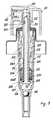
- the reference numeral 1indicates a conventional dispensing knob provided with a pulverization or atomization nozzle 2.
- the knob 1is conventionally connected to a stem 3 a part of which is axially hollow, namely at that end which projects from a gasket 4 which seals against the stem and is enclosed within a cap 5 or cup 6 of conventional type.
- the cap 5preferably of the screwed type, enables the pump to be connected to a suitable vessel or bottle 7, whereas the cup 6 enables it to be connected to a canister 8 or other similar container.
- the stem 3In an intermediate position the stem 3 comprises an annular enlargement 9 and in proximity to its other end is provided with radial ports 10 which communicate with the dead-bottomed axial cavity 11 of the stem 3.
- the stem 3is slidingly guided through the gasket 4 and is arranged to move axially within a hollow plastics body 12 which forms the pump body and which at its internally conical upper end 12A is clamped in the gasket 4 by cooperation between a flange surrounding said end 12A and an inner annular shoulder 13 of the gasket itself.
- the spring 14also comprises a cylindrical part 14B which acts on a piston 15 mounted slidable on the stem 3 from and towards an annular stop ledge 16 provided on the stem 3 at its ports 10.
- the conical end 15A of the piston 15halts against the ledge 10 to thus intercept said ports when the pump is in its rest position.
- the piston 15constructed of elastically deformable plastics material, is provided on its outer periphery with an annular seal flange 15B. Said flange seals against the body 12.
- the piston 15 together with the inner end 3A of the stem 3represents the mobile wall of a suction and metering chamber 17 which is bounded by the rest of the body 12 and by an intake valve 18 which can be a ball (as in Figure 1) or a cylindrical or mushroom shaped member (as in Figure 2).
- a dip tube 19is conventionally connected to the body 12 upstream of the non-return valve.
- the operationis as follows: The initial position (pump inoperative) is that shown in Figure 1. It will be assumed that the chamber 17 is full of liquid. On pressing the knob 1, the liquid contained in the chamber 17 is subjected to pressure. When a given pressure is reached such as to overcome the opposing action of the part 14B of the spring 14, the piston 15 moves to uncover the ports 10 so that the liquid enters the stem 3 and flows in atomized form from the nozzle 2.
- the pressure which acts on the decreasing volume of liquidcorresponds to the load which the part 14B of the spring has to exert to keep the communication between the chamber 17 and ports 10 open.
- the liquid volumereduces the piston 12 and stem 3 move lower.
- the lowering of the stem 3results in the extension of the conical part 14A of the spring 14.
- FIG. 3A different embodiment of the pump according to the invention is shown in Figure 3, in which parts equal or corresponding to those of the embodiment show in Figure 1 are indicated by the same reference numerals plus 100.
- the stem 103is formed from two parts 200, 201, engaged one within the other to define between them a passage for the liquid to be dispensed. More specifically, for the engagement between the two parts, the inner part 200 comprises at one end an annular groove 202 into which there penetrate annularly distributed teeth 203 projecting form the other outer part 201 of the stem 103. The engagement is enabled by the deformability of the plastics materials of which said parts are formed.
- the liquidis able to pass along the stem because the inner part 200 comprises along a portion thereof a series of peripherally distributed axial ribs 204 which centre the two parts 200, 201 and keep them spaced apart.
- the inner part 200 of the stemcomprises at its other end a head 205 of inverted T cross-section which adheres against the corresponding end of the outer part 201 of the stem 103.
- the end of the part 201comprises a series of radial grooves 206 and the head 205 comprises on its inside a series of axial grooves 207.
- the head 205acts as a stop for the piston 115 when this intercepts the passage of liquid towards the stem 103. In this position the inner edge 115A of the piston 115 adheres against the frusto-conical periphery 208 of the head.
- liquidincludes suspensions, solutions, emulsions and the like.
Landscapes
- Reciprocating Pumps (AREA)
- Closures For Containers (AREA)
- Details Of Reciprocating Pumps (AREA)
Description
- This invention relates to a precompression pump, particularly for the atomized dispensing of products in liquid or similar form from a container, of the type comprising a body, an at least partly hollow stem mobile within said body against the action of a return spring, a piston mounted mobile on the stem against the action of elastic means so as to open a passage towards the cavity in the stem, said piston defining with the body a suction and metering chamber, and an intake valve means for the access of said liquid to said chamber.
- Precompression pumps are those pumps which allow the product to be dispensed only when a pressure lying between predetermined limits acts on it. Precompression pumps of the indicated type are known for example from U.S.A. patents 3,463,093 (see Figure 2) and 4,113,145 (see Figure 27).
- In known pumps of this type, the return spring is situated in the suction and metering chamber, so that it is in contact with the liquid to be dispensed. Because of this, the spring even if of stainless steel can contaminate the product by transferring to it any substances, such as lubricants, which were used during the operations involved in the spring manufacture, such as the extrusion of the wire from which it is formed and the subsequent winding of the spring, and have remained on it. This is unacceptable when the product to be dispensed is a pharmaceutical or cosmetics product. In addition, the spring located in the suction and metering chamber considerably increases the clearance volumes of the pump.
- An object of the invention is to remedy the aforesaid drawbacks by removing the return spring from contact with the liquid to be dispensed.
- This and further objects which will be more apparent from the detailed description given hereinafter are attained according to the invention by an improved pump of the indicated type, which is characterised essentially in that the return spring operates under tension and is situated at the opposite end of the piston to that at which the suction and metering chamber is situated.
- To allow considerable automation of pump assembly and to reduce the number of components, according to an important characteristic of the invention the return spring and the elastic means acting on the piston are one and the same spring, a first part of which acts as the return spring and the second part of which loads the piston.
- According to an advantageous embodiment of the invention, the purpose of which is to allow the single spring to be adequately secured to the pump body, its first part is of frusto-conical shape and its second part is of cylindrical shape.
- According to an important characteristic of the invention, the single spring is secured at an intermediate point thereof to the stem.
- In the pump of the invention the conical part of the spring acts under tension and returns the stem and thus the piston into its rest position, whereas the cylindrical part acts by compression and exercises a preload on the piston, which also performs the delivery valve function.
- A further advantage of the improved pump of the invention is that it can also operate by withdrawing liquid from a container, such as a canister under slight overpressure.
- The invention will be more apparent from the detailed description of preferred embodiments thereof given hereinafter by way of non-limiting example with reference to the accompanying drawing in which:
- Figure 1 is a longitudinal section through the improved pump according to the invention;
- Figure 2 is a longitudinal section through a detail of a different intake valve;
- Figure 3 is a longitudinal section through a different embodiment of the invention.
- In Figure 1, the
reference numeral 1 indicates a conventional dispensing knob provided with a pulverization oratomization nozzle 2. Theknob 1 is conventionally connected to a stem 3 a part of which is axially hollow, namely at that end which projects from agasket 4 which seals against the stem and is enclosed within acap 5 or cup 6 of conventional type. - The
cap 5, preferably of the screwed type, enables the pump to be connected to a suitable vessel orbottle 7, whereas the cup 6 enables it to be connected to acanister 8 or other similar container. - In an intermediate position the
stem 3 comprises anannular enlargement 9 and in proximity to its other end is provided withradial ports 10 which communicate with the dead-bottomed axial cavity 11 of thestem 3. - The
stem 3 is slidingly guided through thegasket 4 and is arranged to move axially within ahollow plastics body 12 which forms the pump body and which at its internally conicalupper end 12A is clamped in thegasket 4 by cooperation between a flange surrounding saidend 12A and an innerannular shoulder 13 of the gasket itself. - Between the
gasket 4 and the conical interior of theend 12A of thebody 12 there is held the end of aconical part 14A of a one-piece spring 14. The other end of saidconical part 14A grips theannular enlargement 9 of thestem 3 so that it moves axially with this latter. - The
spring 14 also comprises acylindrical part 14B which acts on apiston 15 mounted slidable on thestem 3 from and towards anannular stop ledge 16 provided on thestem 3 at itsports 10. Theconical end 15A of thepiston 15 halts against theledge 10 to thus intercept said ports when the pump is in its rest position. - The
piston 15, constructed of elastically deformable plastics material, is provided on its outer periphery with an annular seal flange 15B. Said flange seals against thebody 12. - The
piston 15 together with theinner end 3A of thestem 3 represents the mobile wall of a suction andmetering chamber 17 which is bounded by the rest of thebody 12 and by anintake valve 18 which can be a ball (as in Figure 1) or a cylindrical or mushroom shaped member (as in Figure 2). - A
dip tube 19 is conventionally connected to thebody 12 upstream of the non-return valve. - The operation is as follows:
The initial position (pump inoperative) is that shown in Figure 1. It will be assumed that thechamber 17 is full of liquid. On pressing theknob 1, the liquid contained in thechamber 17 is subjected to pressure. When a given pressure is reached such as to overcome the opposing action of thepart 14B of thespring 14, thepiston 15 moves to uncover theports 10 so that the liquid enters thestem 3 and flows in atomized form from thenozzle 2. - The pressure which acts on the decreasing volume of liquid corresponds to the load which the
part 14B of the spring has to exert to keep the communication between thechamber 17 andports 10 open. As the liquid volume reduces thepiston 12 and stem 3 move lower. The lowering of thestem 3 results in the extension of theconical part 14A of thespring 14. - When the travel stroke is terminated and the
knob 1 is released, thecylindrical part 14B of thespring 14 moves thepiston 15 so that it closes theports 10, while theconical part 15A returns thestem 3 andpiston 15 into their initial positions. The effect of this movement is that theintake valve 18 opens and new liquid is drawn into thevariable volume chamber 17 through thedip tube 19. The movement stops when the conically shapedouter rim 20 adheres tightly against a suitably shaped inner annular lip of thegasket 4 to prohibit passage of air into the pump, such passage however being allowed during the travel of thestem 3 by virtue for example of a smallaxial groove 21A provided in the wall of the hole 4A through thegasket 4, this being the hole through which thestem 3 passes. Said groove is closed by theedge 20 of theenlargement 9 when in the position shown in Figure 1. - A different embodiment of the pump according to the invention is shown in Figure 3, in which parts equal or corresponding to those of the embodiment show in Figure 1 are indicated by the same reference numerals plus 100.
- In this embodiment the
stem 103 is formed from twoparts inner part 200 comprises at one end anannular groove 202 into which there penetrate annularlydistributed teeth 203 projecting form the otherouter part 201 of thestem 103. The engagement is enabled by the deformability of the plastics materials of which said parts are formed. - The liquid is able to pass along the stem because the
inner part 200 comprises along a portion thereof a series of peripherally distributedaxial ribs 204 which centre the twoparts - The
inner part 200 of the stem comprises at its other end ahead 205 of inverted T cross-section which adheres against the corresponding end of theouter part 201 of thestem 103. To allow the liquid to pass, the end of thepart 201 comprises a series ofradial grooves 206 and thehead 205 comprises on its inside a series ofaxial grooves 207. - The
head 205 acts as a stop for thepiston 115 when this intercepts the passage of liquid towards thestem 103. In this position theinner edge 115A of thepiston 115 adheres against the frusto-conical periphery 208 of the head. - The operation corresponds to that of the previously described embodiment.
- Where used herein, the term "liquid" includes suspensions, solutions, emulsions and the like.
Claims (7)
Applications Claiming Priority (2)
| Application Number | Priority Date | Filing Date | Title |
|---|---|---|---|
| IT2290688 | 1988-12-09 | ||
| IT8822906AIT1227547B (en) | 1988-12-09 | 1988-12-09 | PERFECTED PRECOMPRESSION PUMP, FOR THE DISPENSING OF LIQUID PRODUCTS FROM CONTAINERS |
Publications (3)
| Publication Number | Publication Date |
|---|---|
| EP0374348A2 EP0374348A2 (en) | 1990-06-27 |
| EP0374348A3 EP0374348A3 (en) | 1990-07-18 |
| EP0374348B1true EP0374348B1 (en) | 1992-05-06 |
Family
ID=11201755
Family Applications (1)
| Application Number | Title | Priority Date | Filing Date |
|---|---|---|---|
| EP89105390AExpiredEP0374348B1 (en) | 1988-12-09 | 1989-03-27 | Improved precompression pump, for dispensing liquid products from vessels |
Country Status (7)
| Country | Link |
|---|---|
| US (1) | US5002207A (en) |
| EP (1) | EP0374348B1 (en) |
| JP (1) | JP2899606B2 (en) |
| AR (1) | AR241043A1 (en) |
| DE (1) | DE68901450D1 (en) |
| ES (1) | ES2031652T3 (en) |
| IT (1) | IT1227547B (en) |
Families Citing this family (22)
| Publication number | Priority date | Publication date | Assignee | Title |
|---|---|---|---|---|
| FR2652389B1 (en)* | 1989-09-26 | 1992-12-04 | Debard Andre | IMPROVEMENT IN PRE-PRESSURE PUMPS FOR THE DISTRIBUTION OF A LIQUID. |
| DE4129474A1 (en)* | 1991-09-05 | 1993-03-11 | Pfeiffer Erich Gmbh & Co Kg | DISCHARGE DEVICE FOR MEDIA |
| IT1251684B (en)* | 1991-10-11 | 1995-05-19 | Carlo Mancini | MANUALLY OPERATED PUMP TO DISPENSE LIQUID OR CREAMY SUBSTANCES AT CONSTANT PRESSURE AND PERFORMANCE. |
| US5359238A (en)* | 1992-08-04 | 1994-10-25 | Ford Motor Company | Analog to digital interface circuit with internal resistance compensation and integrity verification |
| US5655688A (en)* | 1994-10-19 | 1997-08-12 | Aptargroup, Inc. | Atomizing pump with high stroke speed enhancement and valve system therefor |
| US5553757A (en)* | 1995-03-14 | 1996-09-10 | Wang; Ming-Teh | Cream dispenser head |
| SI9600118A (en)* | 1995-04-13 | 1996-10-31 | Monturas Sa | Precompression pump sprayer |
| US6050457A (en)* | 1995-12-06 | 2000-04-18 | The Procter & Gamble Company | High pressure manually-actuated spray pump |
| US5850948A (en)* | 1996-09-13 | 1998-12-22 | Valois S.A. | Finger-operable pump with piston biasing post |
| US6158617A (en)* | 1996-10-30 | 2000-12-12 | The Procter & Gamble Company | Concentrated reduced dosage spray pump delivery system |
| CN1385247A (en)* | 2001-05-11 | 2002-12-18 | 增田胜利 | Pump for spraying pump |
| JP2003341765A (en)* | 2002-05-20 | 2003-12-03 | Katsutoshi Masuda | Valve mechanism of liquid container |
| US6685062B1 (en)* | 2002-09-16 | 2004-02-03 | Yon Woo Corporation | Dispenser pump |
| FR2885887B1 (en)* | 2005-05-20 | 2010-11-05 | Rexam Dispensing Sys | POINTE PUMP FOR THE DISTRIBUTION OF LIQUID PRODUCT |
| US8618164B2 (en) | 2009-03-31 | 2013-12-31 | Nuvo Research Inc. | Treatment of pain with topical diclofenac compounds |
| US20110303702A1 (en)* | 2010-06-11 | 2011-12-15 | Derxin (Shanghai) Cosmetics Co., Ltd. | Liquid spray head assembly |
| US9254954B2 (en) | 2010-08-18 | 2016-02-09 | Summit Packaging Systems, Inc. | Metering valve |
| FR2993542B1 (en)* | 2012-07-19 | 2015-04-10 | Aptar France Sas | FLUID PRODUCT DISPENSING MEMBER. |
| US20140113970A1 (en)* | 2012-10-22 | 2014-04-24 | Mallinckrodt LLC Covidien | Dispensing system |
| CN105736277B (en)* | 2014-12-10 | 2018-06-19 | 富泰华工业(深圳)有限公司 | Fluid supply apparatus |
| GB201603857D0 (en)* | 2016-03-07 | 2016-04-20 | Rieke Packaging Systems Ltd | Dispenser pumps |
| JP2018015685A (en)* | 2016-07-25 | 2018-02-01 | 株式会社丸一 | Spring pressure accumulation type spray pump |
Family Cites Families (10)
| Publication number | Priority date | Publication date | Assignee | Title |
|---|---|---|---|---|
| US3248022A (en)* | 1963-06-21 | 1966-04-26 | Valve Corp Of America | Atomizer pump |
| DE1302372C2 (en)* | 1967-01-17 | 1978-06-08 | Pfeiffer Zerstäuber-Vertriebsgesellschaft mbH & Co KG, 7760 Radolfzell | SINGLE-ACTING MANUAL PISTON PUMP BUILT IN A VESSEL |
| US3500761A (en)* | 1968-07-01 | 1970-03-17 | Cook Chem Co | Control valve for hand pumps |
| US4061247A (en)* | 1973-03-08 | 1977-12-06 | Philip Meshberg | Method of and apparatus for controlling of travel of the plunger in a dispensing pump chamber |
| FR2320788A2 (en)* | 1975-08-14 | 1977-03-11 | Pulverisation Step Ste Tech | IMPROVEMENTS PROVIDED TO VAPORIZERS |
| US4053086A (en)* | 1976-03-31 | 1977-10-11 | Aerosol Inventions & Development S.A. Aid Sa | Pumps for hand-held dispensers |
| IT1092596B (en)* | 1978-02-09 | 1985-07-12 | Ruscitti Tommaso | HAND PUMP TO DISPENSE MICRONIZED LIQUIDS AT PRESTABLE PRESSURE |
| DE3225692A1 (en)* | 1982-07-09 | 1984-01-12 | Pfeiffer Zerstäuber Vertriebsgesellschaft mbH & Co KG, 7760 Radolfzell | DOSING PUMP AND METHOD AND DEVICE FOR FILLING A CONTAINER PROVIDED WITH A DOSING PUMP |
| FR2612890B1 (en)* | 1987-03-26 | 1989-12-29 | Step Soc Tech Pulverisation | DOSER ASSEMBLY FOR PASTY OR SEMI-LIQUID PRODUCT |
| IT211917Z2 (en)* | 1987-07-30 | 1989-05-25 | Elettro Plastica Srl | DISPENSING PUMP APPLICABLE TO FLUID CONTAINERS. |
- 1988
- 1988-12-09ITIT8822906Apatent/IT1227547B/enactive
- 1989
- 1989-03-27DEDE8989105390Tpatent/DE68901450D1/ennot_activeExpired - Lifetime
- 1989-03-27ESES198989105390Tpatent/ES2031652T3/ennot_activeExpired - Lifetime
- 1989-03-27EPEP89105390Apatent/EP0374348B1/ennot_activeExpired
- 1989-11-07USUS07/432,535patent/US5002207A/ennot_activeExpired - Lifetime
- 1989-12-01JPJP1313099Apatent/JP2899606B2/ennot_activeExpired - Lifetime
- 1989-12-06ARAR315618Apatent/AR241043A1/enactive
Also Published As
| Publication number | Publication date |
|---|---|
| JP2899606B2 (en) | 1999-06-02 |
| JPH02203952A (en) | 1990-08-13 |
| EP0374348A3 (en) | 1990-07-18 |
| DE68901450D1 (en) | 1992-06-11 |
| IT8822906A0 (en) | 1988-12-09 |
| EP0374348A2 (en) | 1990-06-27 |
| AR241043A1 (en) | 1991-04-30 |
| ES2031652T3 (en) | 1992-12-16 |
| US5002207A (en) | 1991-03-26 |
| AR241043A2 (en) | 1991-04-30 |
| IT1227547B (en) | 1991-04-15 |
Similar Documents
| Publication | Publication Date | Title |
|---|---|---|
| EP0374348B1 (en) | Improved precompression pump, for dispensing liquid products from vessels | |
| CA1053623A (en) | Dispensing pump | |
| US5482188A (en) | Precompression pump | |
| EP0755305B1 (en) | Manually operated reciprocating liquid pump | |
| US4762475A (en) | Thrust piston pump for the discharge of media | |
| US4775079A (en) | Upright/inverted pump sprayer | |
| US4191313A (en) | Trigger operated dispenser with means for obtaining continuous or intermittent discharge | |
| US5803318A (en) | Precompression pump | |
| CA2070080C (en) | Liquid pump dispenser having a stationary spout | |
| US4503996A (en) | Liquid atomizer having a double-acting pump | |
| US4155489A (en) | Leakproof pump for hand-held dispensers | |
| US4692103A (en) | Precise output pump sprayer | |
| IE50974B1 (en) | Liquid dispensing pump | |
| CA2083975C (en) | Miniature pump dispenser | |
| GB2176543A (en) | Manually operated pump | |
| CA2174022A1 (en) | A device for packaging and dispensing a liquid or semi-liquid substance | |
| US4056216A (en) | Liquid dispensing pump automatically sealable against leakage | |
| US4022354A (en) | Accumulator release pump | |
| US4311255A (en) | Hand held container and dispenser assembly | |
| US5850948A (en) | Finger-operable pump with piston biasing post | |
| US4087025A (en) | Leakproof pump for hand-held dispensers | |
| US5709325A (en) | Manual precompression pump for spraying a liquid, and dispensing assembly equipped with such a pump | |
| EP0484615A1 (en) | Manually operated pump device for dispensing fluids | |
| EP0342651B1 (en) | Dosing pump | |
| US5715973A (en) | Manually operated fluid pump for dispensing lotion and the like |
Legal Events
| Date | Code | Title | Description |
|---|---|---|---|
| PUAI | Public reference made under article 153(3) epc to a published international application that has entered the european phase | Free format text:ORIGINAL CODE: 0009012 | |
| PUAL | Search report despatched | Free format text:ORIGINAL CODE: 0009013 | |
| AK | Designated contracting states | Kind code of ref document:A2 Designated state(s):DE ES FR GB IT | |
| AK | Designated contracting states | Kind code of ref document:A3 Designated state(s):DE ES FR GB IT | |
| 17P | Request for examination filed | Effective date:19900805 | |
| 17Q | First examination report despatched | Effective date:19911014 | |
| GRAA | (expected) grant | Free format text:ORIGINAL CODE: 0009210 | |
| AK | Designated contracting states | Kind code of ref document:B1 Designated state(s):DE ES FR GB IT | |
| REF | Corresponds to: | Ref document number:68901450 Country of ref document:DE Date of ref document:19920611 | |
| ET | Fr: translation filed | ||
| ITF | It: translation for a ep patent filed | ||
| REG | Reference to a national code | Ref country code:ES Ref legal event code:FG2A Ref document number:2031652 Country of ref document:ES Kind code of ref document:T3 | |
| PLBE | No opposition filed within time limit | Free format text:ORIGINAL CODE: 0009261 | |
| STAA | Information on the status of an ep patent application or granted ep patent | Free format text:STATUS: NO OPPOSITION FILED WITHIN TIME LIMIT | |
| 26N | No opposition filed | ||
| REG | Reference to a national code | Ref country code:GB Ref legal event code:IF02 | |
| PGFP | Annual fee paid to national office [announced via postgrant information from national office to epo] | Ref country code:ES Payment date:20080218 Year of fee payment:20 | |
| PGFP | Annual fee paid to national office [announced via postgrant information from national office to epo] | Ref country code:IT Payment date:20080226 Year of fee payment:20 Ref country code:GB Payment date:20080328 Year of fee payment:20 | |
| PGFP | Annual fee paid to national office [announced via postgrant information from national office to epo] | Ref country code:DE Payment date:20080311 Year of fee payment:20 | |
| REG | Reference to a national code | Ref country code:GB Ref legal event code:PE20 Expiry date:20090326 | |
| REG | Reference to a national code | Ref country code:ES Ref legal event code:FD2A Effective date:20090328 | |
| PG25 | Lapsed in a contracting state [announced via postgrant information from national office to epo] | Ref country code:GB Free format text:LAPSE BECAUSE OF EXPIRATION OF PROTECTION Effective date:20090326 | |
| PG25 | Lapsed in a contracting state [announced via postgrant information from national office to epo] | Ref country code:ES Free format text:LAPSE BECAUSE OF EXPIRATION OF PROTECTION Effective date:20090328 | |
| PGFP | Annual fee paid to national office [announced via postgrant information from national office to epo] | Ref country code:FR Payment date:20080328 Year of fee payment:20 |