EP0364822B1 - Table with a frame and a top as well as an adjusting device for varying the height and the inclination of the top of the table - Google Patents
Table with a frame and a top as well as an adjusting device for varying the height and the inclination of the top of the tableDownload PDFInfo
- Publication number
- EP0364822B1 EP0364822B1EP89118474AEP89118474AEP0364822B1EP 0364822 B1EP0364822 B1EP 0364822B1EP 89118474 AEP89118474 AEP 89118474AEP 89118474 AEP89118474 AEP 89118474AEP 0364822 B1EP0364822 B1EP 0364822B1
- Authority
- EP
- European Patent Office
- Prior art keywords
- support means
- drive
- threaded
- frame
- table according
- Prior art date
- Legal status (The legal status is an assumption and is not a legal conclusion. Google has not performed a legal analysis and makes no representation as to the accuracy of the status listed.)
- Expired - Lifetime
Links
Images


Classifications
- A—HUMAN NECESSITIES
- A47—FURNITURE; DOMESTIC ARTICLES OR APPLIANCES; COFFEE MILLS; SPICE MILLS; SUCTION CLEANERS IN GENERAL
- A47B—TABLES; DESKS; OFFICE FURNITURE; CABINETS; DRAWERS; GENERAL DETAILS OF FURNITURE
- A47B17/00—Writing-tables
- A47B17/02—Writing-tables with vertically-adjustable parts
- A—HUMAN NECESSITIES
- A47—FURNITURE; DOMESTIC ARTICLES OR APPLIANCES; COFFEE MILLS; SPICE MILLS; SUCTION CLEANERS IN GENERAL
- A47B—TABLES; DESKS; OFFICE FURNITURE; CABINETS; DRAWERS; GENERAL DETAILS OF FURNITURE
- A47B9/00—Tables with tops of variable height
- A47B9/04—Tables with tops of variable height with vertical spindle
- A—HUMAN NECESSITIES
- A47—FURNITURE; DOMESTIC ARTICLES OR APPLIANCES; COFFEE MILLS; SPICE MILLS; SUCTION CLEANERS IN GENERAL
- A47B—TABLES; DESKS; OFFICE FURNITURE; CABINETS; DRAWERS; GENERAL DETAILS OF FURNITURE
- A47B9/00—Tables with tops of variable height
- A47B9/18—Tables with tops of variable height with additional top or additional legs for varying the height of the top
- A47B2009/185—Tables with tops of variable height with additional top or additional legs for varying the height of the top being positioned between the table top and the legs or underframe
- A—HUMAN NECESSITIES
- A47—FURNITURE; DOMESTIC ARTICLES OR APPLIANCES; COFFEE MILLS; SPICE MILLS; SUCTION CLEANERS IN GENERAL
- A47B—TABLES; DESKS; OFFICE FURNITURE; CABINETS; DRAWERS; GENERAL DETAILS OF FURNITURE
- A47B2200/00—General construction of tables or desks
- A47B2200/0011—Underframes
- A47B2200/0013—Desks with central bearing beams
- A—HUMAN NECESSITIES
- A47—FURNITURE; DOMESTIC ARTICLES OR APPLIANCES; COFFEE MILLS; SPICE MILLS; SUCTION CLEANERS IN GENERAL
- A47B—TABLES; DESKS; OFFICE FURNITURE; CABINETS; DRAWERS; GENERAL DETAILS OF FURNITURE
- A47B2200/00—General construction of tables or desks
- A47B2200/0035—Tables or desks with features relating to adjustability or folding
- A47B2200/004—Top adjustment
- A47B2200/0041—Height adjustable table top with parallel link arms
- A—HUMAN NECESSITIES
- A47—FURNITURE; DOMESTIC ARTICLES OR APPLIANCES; COFFEE MILLS; SPICE MILLS; SUCTION CLEANERS IN GENERAL
- A47B—TABLES; DESKS; OFFICE FURNITURE; CABINETS; DRAWERS; GENERAL DETAILS OF FURNITURE
- A47B2200/00—General construction of tables or desks
- A47B2200/0035—Tables or desks with features relating to adjustability or folding
- A47B2200/004—Top adjustment
- A47B2200/0042—Height and inclination adjustable desktop, either separately or simultaneously
- A—HUMAN NECESSITIES
- A47—FURNITURE; DOMESTIC ARTICLES OR APPLIANCES; COFFEE MILLS; SPICE MILLS; SUCTION CLEANERS IN GENERAL
- A47B—TABLES; DESKS; OFFICE FURNITURE; CABINETS; DRAWERS; GENERAL DETAILS OF FURNITURE
- A47B2200/00—General construction of tables or desks
- A47B2200/0035—Tables or desks with features relating to adjustability or folding
- A47B2200/004—Top adjustment
- A47B2200/0043—Inclination adjustable work top
Definitions
- the inventionrelates to a table with a table frame, a table top and two support devices which are articulated with the one ends on the table frame and with the other ends on the underside of the table top and are pivotable by means of an actuating device, the table top by means of the actuating device both in the Height as well as the inclination is adjustable.
- a table of this typeis known from DE-A-32 24 540.
- the heightcan be adjusted without changing the inclination of the table top.
- the actuating device required for thisrequires a complicated mechanism with many parts, all of which are arranged below the table top and are coupled to the table top and the table frame.
- several lever chainsare provided in the actuating device, which allow an unambiguous adjustment in a limited area, when a secure determination of the set height and inclination of the table top is desired.
- an adjusting device for a tableis known, with which the height or the height and the inclination of the table top can be changed.
- the front edge of the table topmust be actuated in order to actuate a coupling in the actuating device.
- the height of the front edge of the table topremains at approximately the same height.
- This change in the inclination of the table topcauses a simultaneous height adjustment of the table top and the operation of the actuating device is not easy, since in addition to the actuation of the actuating device via the table top, the clutch must be kept actuated.
- DE-A-30 39 180shows a table in which the height and inclination of the table top can also be changed independently of one another.
- two actuating devicesare provided for this purpose, which can be actuated separately, the actuating points being locally separated from one another.
- the support devices in the upper region of the transverse center of the table frameare articulated about transverse pivot axes on the table frame, that the support devices on the underside of the tabletop are supported on transverse pivot axes on the table top, but in the depth of the table top are adjustable so that the adjusting device pivots the support devices either individually or together towards the table top or lowers towards the table frame, the table-side pivot axes of the support devices moving towards or away from each other, and that when pivoting a support device only the inclination of the table top and only the height of the table top can be changed when the two supporting devices are pivoted together while maintaining the inclination.
- the adjustment mechanismonly requires the two support devices which are fixed to the table frame, but can be swiveled and swiveled on the table top and are adjustable perpendicular to the swivel axis. With the adjusting device, the support devices can be pivoted individually or together, and it is then automatically determined whether only the inclination of the table top or only the height of the table top is changed while maintaining the inclination.
- each support deviceis designed as a pair of pivot levers spaced apart in the transverse direction.
- each support deviceis designed as a plate-shaped support cheek extending over the essential part of the transverse direction.
- each support deviceis supported on the table top via two joints forming the pivot axis, that the joints are arranged on sliders that are guided in pairs and in opposite directions in guide rails, and that the guide rails extend towards the depth of the table top.
- the guide railsare designed as C-profile sections, and that the sliders carry tabs which protrude from the guide rails and are designed for articulating the support devices. The sliders are clearly guided and offer an easy way to link the support devices without limiting their swivel range.
- the articulation of the support devices on the table frameis solved according to one embodiment so that the table frame has two lateral supports resting on feet, which are connected to one another in the region of the upper transverse center by means of a frame, and that the support devices in the region of the front and rear side of the frame are articulated.
- a further embodimentprovides that at least one guide arm is articulated on the underside of the table top between the support devices, which is articulated in the area of the rear side of the table Frame supported on the table frame.
- a spur gearis rotatably mounted between the two sliders, the axis of rotation running in the transverse direction of the table top, that the spur gear is diametrically engaged with two racks which run along the guide rail and are firmly connected to the adjustable glides in this guide rail.
- the pivoting movementscan be transmitted to the support devices in such a way that two threaded spindles running in the longitudinal direction of the guide rails are used as the adjusting device, which are adjustable in threaded bores of the sliders, but are non-displaceable and freely rotatable on the underside of the table top.
- the threaded spindles assigned to the adjusting devicescan be driven individually or together depending on whether the inclination or the height of the table top is to be changed.
- a common threaded spindle with two opposite threaded sectionsis used as the adjusting device for the two sliders adjustable in a guide rail is, which is adjustable in corresponding counter-threaded bores of the slider, but is immovable and freely rotatable on the underside of the table top.
- the option of changing the height or the inclinationis additionally provided that the two threaded sections of the threaded spindle are connected to one another by means of a coupling, that only a drive section is assigned to the threaded section directed towards the front of the table top, and that when the coupling is engaged, the height and at disengaged clutch the inclination of the table top can be changed by means of the single drive.
- each support deviceis guided into the two supports of the table frame by means of an extension, that each extension is coupled to a driver which is adjustable on a horizontal threaded shaft rotatably mounted in the support, that each Threaded shaft rotatably supports a drive pulley that the drive pulleys assigned to a support device can be set in rotation by means of an endless ball chain that can be operated in both directions, and that at least one, preferably the endless ball chain assigned to the front support device can be driven individually and both endless ball chains can be driven together are.
- the common drive of the two endless ball chains for changing the height of the table topis facilitated by the fact that the threaded shafts assigned to the two support devices have opposite sense of thread and that the two endless ball chains rotate in the same direction when the drive is common, since both drive coupling disks only with the Drive must be coupled, which is achieved in a particularly simple manner in that the endless ball chains over each an arranged on the underside of the table top drive coupling plate are guided, that the two drive coupling plates are arranged one behind the other with a common axis of rotation, and that as a drive a hand crank or a drive motor can be optionally coupled to one or both drive receptacles of the drive coupling plates. It is sufficient to fix the hoses or pipes in the base frame in order to obtain a defined circulation of the endless ball chains between the drive coupling plates and the drive plates on the threaded shafts.
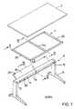
- Fig. 1shows a table according to the invention from top to bottom, the table top 2, including the frame 4, which is made of hollow profiles made of light metal.
- Base 6with feet 8 can be seen, the front parts of which are longer than the rear parts.
- the feet 8carry two supports 10 and the frame 12 which is fastened between the two supports 10 and connects them to one another.
- the frame 12is designed as a hollow box profile and has the shape of a U open in cross-section.
- Two support devices 14 and 15 designed as support platesare pivotably attached to the frame 12.
- the tablehas the front support device 14 and the rear support device 15.
- the support devices 14 and 15are formed as hollow profiles made of sheet metal, which can be reinforced by transverse beads.
- Both actuators 14 and 15are pivotally mounted on the frame 12 about the axes 16 and 17 which run in their longitudinal direction, ie in the transverse direction of the table top.
- the arm 18is pivotally mounted, likewise about the axis 17 running in the longitudinal direction thereof.
- 3 to 5show how the table top 2 can be adjusted. If the two support devices 14 and 15 are swiveled upwards together, the table top 2 is raised, both adjusting devices 14 and 15 are swiveled downwards together, then the table top 2 is also lowered. If the rear adjusting device 15 remains at the top while the front adjusting device 14 is being lowered, the table top 2 assumes a forward inclination which is determined by the pivoting angle of the front supporting device 14.
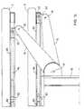
- FIG. 7which can be put together to form a single figure, provide details for the adjustment of the support devices 14 and 15.
- the support devices 14 and 15have their edges facing away from the frame 12 and are close their outer right and left ends, two tabs 20, which are rigidly attached to the supports 14 and 15.
- the outer ends of the tabs 20are each mounted in a slider 22 or 23 with an internal thread about axes 24.
- the front (22) and the rear sliders 23are slidably guided in downwardly open C-profiles as guide rails 26 of the frame 4.
- Two sections 28 and 29 of a threaded spindle 27are rotatably and non-displaceably mounted in the guide rails 26 designed as a C-profile.
- Sections 28 and 29have opposite threads, e.g. the front section 18 is a right-hand thread, the rear section 29 is a left-hand thread.
- Corresponding internal threadshave the associated front and rear sliders 22 and 23, respectively. Between the two sections 28 and 29 of the threaded spindles there is a coupling 32.
- the clutch 32is held engaged by a compression spring 34, it can be pulled over the tension element 36, e.g. a wire, disengage with the hand button 38 and, after releasing the hand button 38, returns to the position shown in which the two sections 28, 29 are coupled to one another.
- the hand crank 40which is formed from the turntable 42 and the foldable handle 44, is used to drive the front section 28 of the threaded spindle 27.
- the crank handle 40is in drive connection with the front section 28 of the threaded spindle 27 via the angular gear 46.
- the rear section 29 of the threaded spindle 27is also rotated via the clutch 32, namely in the same direction of rotation. Since both sections 28 and 29 have opposite threads, in one direction of rotation the hand crank 40, for example, the slider 22 is moved forward (to the left in FIG. 2a), the slider 23, however, is moved backwards. As a result, the supports 14 and 15 and the table top 2 lowered. In the opposite direction of rotation of the crank handle 40, the support devices 14 and 15 and the table top 2 are raised accordingly.
- the threaded spindles 27can also be coupled so that they are e.g. a single crank handle 40, are rotatable.
- electric motorsin particular tubular motors, can also be provided, which can be driven in opposite directions of rotation.
- the arm 18is located approximately in the middle of the table (viewed from left to right), which initially serves to secure the table top 2 against displacement from the front to the rear. Since the described sliders 22, 23 are freely displaceable in the guide rails 26 of the frame 4, this means that the entire frame 4 and thus the table top 2 can be freely moved from front to back, regardless of the setting of the table top 2 in height and of inclination.
- the arm 18is mounted on the rear of the frame 12 so as to be freely pivotable about the axis 50 running in the longitudinal direction thereof (cf. FIG. 6).
- the upper end of the arm 18is articulated to the slider 52.
- the slider 52is freely displaceably mounted in a C-profile 54.
- the C-profile 54forms the center of the frame 4 (Fig. 1).
- An additional threaded spindle 56is rotatably mounted in the C-profile 54. In contrast to the previously described threaded spindles 27, this has only one thread in one thread. It can also be powered by a hand crank or a motor. If the threaded spindle 56 is actuated, then it moves the C-profile 54 forwards or backwards relative to the slider 52 which remains in its position, so that the table top 2 is displaced in the same sense.
- the arm 18is articulated at both ends, as the axes 50 and 58 show. The arm 18 consequently makes all upward and downward movements of the table top 2 and ensures in its respective position that the table top 2 does not automatically move forward or backward, in particular when used in a set inclination.
- the U-shaped frame 12 and the space above the frame 12 and between the actuators 14 and 15 and the frame 4can be used to accommodate cables and accessories.
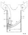
- FIG. 8shows another exemplary embodiment for an actuating device. Only the part of the actuating device as shown per support 10 is shown.
- the support devices 14 and 15which are pivotably mounted on the front and rear side of the frame 12, as can be seen from the pivot axes 16 and 17, are inserted into the support 10 with extensions 60 and 61. These extensions 60 and 61 are in receptacles of drivers 62 and 63, which are adjustable on the threaded shafts 64 and 65.
- These threaded shafts 64 and 65like the bearings 71, are rotatably mounted in an additional profile 70 which is inserted into the support 10. The bearing points of the threaded shafts 64 and 65 are therefore not visible on the outside of the support 10.
- each threaded shaft 64 or 65rotatably carries a drive pulley 66 or 67, over which an endless ball chain 68 or 69 is guided as a drive means.
- the drive of the threaded shaft 64 and 65can be different.
- the two threaded shafts 64 and 65are also actuated in the same direction of rotation. Then the threaded shafts 64 and 65 and the threads in the drivers 62 and 63 must run in opposite directions Have a sense of thread to maintain the opposite movements of the drivers 62 and 63. However, if the threaded shafts 64 and 65 are formed identically with the drivers 62 and 63, then the endless ball chains 68 and 69 must each run in opposite directions for a common adjustment of the two support devices 14 and 15. In each case, the possibility must be provided to individually drive at least one of the endless ball chains 68 and 69.
- each endless ball chain 68 or 69a drive coupling disk 74 or 75, which have drive receptacles 77 and 78 aligned on a common axis 76.
- the drive, a hand crank, an output shaft of a drive motor or the like,is then optionally inserted only into the drive receptacle 77 or into both drive receptacles 77 and 78, as shown in FIG. 11.
- the endless ball chain 68can be driven alone or both endless ball chains 68 and 69 are driven in the same direction. Therefore, the thread direction of the thread shafts 64 and 65 should be selected in opposite directions.
- the endless ball chains 68 and 69are guided between the drive coupling disks 74 and 75 and the drive disks 64 and 65 in hoses or tubes 72 and 73.
- cages 80guide the endless ball chains 68 and 69 and ensure the drive connection.
- Fig. 13shows how actuators in both supports 10 of the table frame can be drawn into the endless ball chain drive.
- the endless ball chain 68 in the hose or tube 72leads over the drive coupling disk 74 and the drive shafts 64 and 64 'assigned drive disks 66 and 66' in the same direction of rotation, so that the threaded shafts 64 and 64 ', which are assigned to the support device 14, circulate in the same way.
- the endless ball chain 68 in the hose or tube 73runs over the drive coupling disk 75 and the threaded shafts 65 and 65 'associated drive disks 66 and 66' in the same direction of rotation, so that the threaded shafts 65 and 65 'which are assigned to the support device 15 in same way and also as the threaded shafts 64 and 64 'revolve.
- both support devices 14 and 15are therefore raised or lowered depending on the direction of rotation of the endless ball chains 68 and 69. 13 is that the threaded shafts 64 and 64 'with their drivers have an opposite thread as the threaded shafts 65 and 65' with their drivers in order to maintain the opposite movement of the drivers and support devices.
- the position of the table top 2can also be fixed by a spur gear 82 and two racks 83 and 84 in the direction of the depth of the table top 2, as shown in FIG. 14.
- the spur gear 82is rotatably mounted in the guide rail 26 between the sliders 22 and 23.
- the axis of rotationextends in the transverse direction of the table top 2.
- the two racks 83 and 84are arranged diametrically on the spur gear 82 and are in engagement with it.
- the ends of the racks 83 and 84 facing away from the spur gear 82are fixedly connected to the sliders 22 and 23, so that they are adjusted synchronously with them. This ensures that the table top 2 does not move in the direction of the depth of the table top 2 even when the height is changed.
- This forced fixation of the table top 2is preferably carried out in each of two guide rails 26 in order to be able to adjust even large and heavy table tops 2 without tilting in height and inclination.
Landscapes
- Tables And Desks Characterized By Structural Shape (AREA)
- Accommodation For Nursing Or Treatment Tables (AREA)
Abstract
Description
Translated fromGermanDie Erfindung betrifft einen Tisch mit einem Tischgestell, einer Tischplatte und zwei Stützeinrichtungen, die mit den einen Enden am Tischgestell und mit den anderen Enden an der Unterseite der Tischplatte gelenkig abgestützt und mittels einer Stelleinrichtung verschwenkbar sind, wobei die Tischplatte mittels der Stelleinrichtung sowohl in der Höhe als auch in der Neigung einstellbar ist.The invention relates to a table with a table frame, a table top and two support devices which are articulated with the one ends on the table frame and with the other ends on the underside of the table top and are pivotable by means of an actuating device, the table top by means of the actuating device both in the Height as well as the inclination is adjustable.
Ein Tisch dieser Art ist durch die DE-A-32 24 540 bekannt. Bei diesem bekannten Tisch kann die Höhenverstellung vorgenommen werden, ohne daß sich dabei die eingestellte Neigung der Tischplatte verändert. Die dazu erforderliche Stelleinrichtung erfordert eine komplizierte Mechanik mit vielen Teilen, die alle unterhalb der Tischplatte angeordnet und mit der Tischplatte und dem Tischgestell gekoppelt sind. Insbesondere sind in der Stelleinrichtung mehrere Hebelketten vorgesehen, die eine eindeutige Verstellung in einem beschränkten Bereich zulassen, wenn eine sichere Festlegung der eingestellten Höhe und Neigung der Tischplatte gewünscht ist.A table of this type is known from DE-A-32 24 540. In this known table, the height can be adjusted without changing the inclination of the table top. The actuating device required for this requires a complicated mechanism with many parts, all of which are arranged below the table top and are coupled to the table top and the table frame. In particular, several lever chains are provided in the actuating device, which allow an unambiguous adjustment in a limited area, when a secure determination of the set height and inclination of the table top is desired.
Wie die FR-A-1 305 255 zeigt, ist es auch bekannt, die Höhe und die Neigung der Tischplatte unabhängig voneinander zu verändern, wobei bei der Höhenverstellung die Neigung der Tischplatte ebenfalls erhalten bleibt. Die Verstellkraft muß bei diesem bekannten Tisch in voller Größe manuell aufgebracht werden, so daß diese bekannte Stelleinrichtung für Arbeits- und Bürotische mit schwerer Tischplatte ausscheidet.As FR-A-1 305 255 shows, it is also known to change the height and the inclination of the table top independently of one another, the inclination of the table top also being retained during the height adjustment. The adjustment force must be applied manually in full size in this known table, so that this known adjusting device for work and office tables with a heavy table top is eliminated.
Aus der CH-A-669 502 ist eine Stelleinrichtung für einen Tisch bekannt, mit der wahlweise die Höhe oder die Höhe und die Neigung der Tischplatte verändert werden kann. Dabei muß bei der gleichzeitigen Änderung der Höhe und der Neigung der Tischplatte die Vorderkante der Tischplatte betätigt werden, um eine Kupplung in der Stelleinrichtung zu betätigen. Bei dieser Verstellung bleibt die Höhe der Vorderkante der Tischplatte etwa in gleicher Höhe. Diese Veränderung der Neigung der Tischplatte bewirkt eine gleichzeitige Höhenverstellung der Tischplatte und die Bedienung der Stelleinrichtung ist nicht einfach, da neben der Betätigung der Stelleinrichtung über die Tischplatte die Kupplung betätigt gehalten werden muß.From CH-A-669 502 an adjusting device for a table is known, with which the height or the height and the inclination of the table top can be changed. When changing the height and the inclination of the table top, the front edge of the table top must be actuated in order to actuate a coupling in the actuating device. With this adjustment, the height of the front edge of the table top remains at approximately the same height. This change in the inclination of the table top causes a simultaneous height adjustment of the table top and the operation of the actuating device is not easy, since in addition to the actuation of the actuating device via the table top, the clutch must be kept actuated.
Die DE-A-30 39 180 zeigt einen Tisch, bei dem ebenfalls die Höhe und die Neigung der Tischplatte unabhängig voneinander veränderbar sind. Dazu sind im Prinzip wieder zwei Stelleinrichtungen vorgesehen, die getrennt betätigbar sind, wobei die Betätigungsstellen örtlich voneinander getrennt sind.DE-A-30 39 180 shows a table in which the height and inclination of the table top can also be changed independently of one another. In principle, two actuating devices are provided for this purpose, which can be actuated separately, the actuating points being locally separated from one another.
Es ist Aufgabe der Erfindung, einen Arbeits- oder Bürotisch der eingangs erwähnten Art zu schaffen, bei dem mit einer einfachen Stelleinrichtung wahlweise nur die Höhe oder nur die Neigung der Tischplatte verändert werden kann, wobei bei der Höhenverstellung die eingestellte Neigung der Tischplatte beibehalten werden soll.It is an object of the invention to provide a work or office table of the type mentioned in the introduction, in which, with a simple adjusting device, either only the height or only the inclination the table top can be changed, whereby the set inclination of the table top should be maintained during the height adjustment.
Diese Aufgabe wird nach der Erfindung dadurch gelöst, daß die Stützeinrichtungen im oberen Bereich der Quermitte des Tischgestelles um in Querrichtung verlaufende Schwenkachsen am Tischgestell angelenkt sind, daß die Stützeinrichtungen auf der Unterseite der Tischplatte sich an in Querrichtung verlaufenden Schwenkachsen an der Tischplatte abstützen, jedoch in der Tiefe der Tischplatte verstellbar geführt sind, daß die Stelleinrichtung die Stützeinrichtungen wahlweise einzeln oder gemeinsam in Richtung zur Tischplatte hochschwenkt oder in Richtung zum Tischgestell absenkt, wobei sich die tischplattenseitigen Schwenkachsen der Stützeinrichtungen aufeinander zu bewegen oder voneinander entfernen, und daß bei der Verschwenkung einer Stützeinrichtung nur die Neigung der Tischplatte und bei der gemeinsamen Verschwenkung beider Stützeinrichtungen unter Beibehaltung der Neigung nur die Höhe der Tischplatte veränderbar ist.This object is achieved according to the invention in that the support devices in the upper region of the transverse center of the table frame are articulated about transverse pivot axes on the table frame, that the support devices on the underside of the tabletop are supported on transverse pivot axes on the table top, but in the depth of the table top are adjustable so that the adjusting device pivots the support devices either individually or together towards the table top or lowers towards the table frame, the table-side pivot axes of the support devices moving towards or away from each other, and that when pivoting a support device only the inclination of the table top and only the height of the table top can be changed when the two supporting devices are pivoted together while maintaining the inclination.
Der Verstellmechanismus erfordert nur die beiden Stützeinrichtungen, die am Tischgestell fest, jedoch schwenkbar und an der Tischplatte schwenkbar und senkrecht zur Schwenkachse verstellbar sind. Mit der Stelleinrichtung können die Stützeinrichtungen einzeln oder gemeinsam verschwenkt werden und damit ist dann automatisch festgelegt, ob nur die Neigung der Tischplatte oder unter Beibehaltung der Neigung nur die Höhe der Tischplatte verändert wird.The adjustment mechanism only requires the two support devices which are fixed to the table frame, but can be swiveled and swiveled on the table top and are adjustable perpendicular to the swivel axis. With the adjusting device, the support devices can be pivoted individually or together, and it is then automatically determined whether only the inclination of the table top or only the height of the table top is changed while maintaining the inclination.
Nach einer Ausgestaltung kann in einfacher Weise vorgesehen sein, daß jede Stützeinrichtung als ein in Querrichtung beabstandetes Paar von Schwenkhebeln ausgebildet ist.According to one embodiment, it can be provided in a simple manner that each support device is designed as a pair of pivot levers spaced apart in the transverse direction.
Aus ästhetischen und statischen Gründen kann die Ausgestaltung auch so ausgeführt sein, daß jede Stützeinrichtung als eine über den wesentlichen Teil der Querrichtung erstreckende, plattenförmige Stützwange ausgebildet ist.For aesthetic and static reasons, the configuration can also be carried out in such a way that each support device is designed as a plate-shaped support cheek extending over the essential part of the transverse direction.
Die Verstellbarkeit der Stützeinrichtungen an der Tischplatte wird in einfacher Weise dadurch erhalten, daß sich jede Stützeinrichtung über zwei die Schwenkachse bildende Gelenke an der Tischplatte abstützt, daß die Gelenke an Gleitern angeordnet sind, die paarweise und gegenläufig verstellbar in Führungsschienen geführt sind, und daß sich die Führungsschienen in Richtung der Tiefe der Tischplatte erstrecken. Dabei ist vorzugsweise vorgesehen, daß die Führungsschienen als C-Profilabschnitte ausgebildet sind, und daß die Gleiter Laschen tragen, die aus den Führungsschienen ragen und zum Anlenken der Stützeinrichtungen ausgebildet sind. Die Gleiter sind eindeutig geführt und bieten eine einfache Möglichkeit zum Anlenken der Stützeinrichtungen ohne deren Schwenkbereich zu begrenzen.The adjustability of the support devices on the table top is obtained in a simple manner in that each support device is supported on the table top via two joints forming the pivot axis, that the joints are arranged on sliders that are guided in pairs and in opposite directions in guide rails, and that the guide rails extend towards the depth of the table top. It is preferably provided that the guide rails are designed as C-profile sections, and that the sliders carry tabs which protrude from the guide rails and are designed for articulating the support devices. The sliders are clearly guided and offer an easy way to link the support devices without limiting their swivel range.
Die Anlenkung der Stützeinrichtungen am Tischgestell ist nach einer Ausgestaltung so gelöst, daß das Tischgestell zwei auf Füßen ruhende seitliche Stützen aufweist, die im Bereich der oberen Quermitte mittels einer Zarge miteinander verbunden sind, und daß die Stützeinrichtungen im Bereich der vorderen und hinteren Seite der Zarge angelenkt sind.The articulation of the support devices on the table frame is solved according to one embodiment so that the table frame has two lateral supports resting on feet, which are connected to one another in the region of the upper transverse center by means of a frame, and that the support devices in the region of the front and rear side of the frame are articulated.
Damit die Tischplatte im Bezug auf die Stelleinrichtungen stets eine definierte Stellung in Richtung der Tiefe der Tischplatte einnimmt, sieht eine weitere Ausgestaltung vor, daß auf der Unterseite der Tischplatte zwischen den Stützeinrichtungen mindestens ein Führungsarm angelenkt ist, der sich gelenkig im Bereich der hinteren Seite der Zarge am Tischgestell abstützt. Dieselbe Wirkung kann auch dadurch erzielt werden, daß zumindest im Bereich einer Führungsschiene zwischen den beiden Gleitern ein Stirnrad drehbar gelagert ist, wobei die Drehachse in Querrichtung der Tischplatte verläuft, daß das Stirnrad diametral mit zwei Zahnstangen im Eingriff steht, die längs der Führungsschiene verlaufen und fest mit den in dieser Führungsschiene verstellbaren Gleitern verbunden sind.So that the table top always assumes a defined position in relation to the actuating devices in the direction of the depth of the table top, a further embodiment provides that at least one guide arm is articulated on the underside of the table top between the support devices, which is articulated in the area of the rear side of the table Frame supported on the table frame. The same effect can also be achieved in that, at least in the area of a guide rail, a spur gear is rotatably mounted between the two sliders, the axis of rotation running in the transverse direction of the table top, that the spur gear is diametrically engaged with two racks which run along the guide rail and are firmly connected to the adjustable glides in this guide rail.
Die Schwenkbewegungen können nach einer Ausgestaltung in der Weise auf die Stützeinrichtungen übertragen werden, daß als Stelleinrichtung zwei in Längsrichtung der Führungsschienen verlaufende Gewindespindeln verwendet sind, die in Gewindebohrungen der Gleiter verstellbar, jedoch unverschiebbar und frei drehbar an der Unterseite der Tischplatte festgelegt sind. Dabei können die den Stelleinrichtungen zugeordneten Gewindespindeln stelleinrichtungsindividuell oder gemeinsam angetrieben werden, je nachdem ob die Neigung oder die Höhe der Tischplatte verändert werden soll. Dabei kann zur Verstellung auch vorgesehen sein, daß als Stelleinrichtung für die beiden in einer Führungsschiene verstellbaren Gleiter eine gemeinsame Gewindespindel mit zwei gegenläufigen Gewindeabschnitten verwendet ist, die in entsprechend gegenläufigen Gewindebohrungen der Gleiter verstellbar, jedoch unverschiebbar und frei drehbar an der Unterseite der Tischplatte festgelegt ist.According to one embodiment, the pivoting movements can be transmitted to the support devices in such a way that two threaded spindles running in the longitudinal direction of the guide rails are used as the adjusting device, which are adjustable in threaded bores of the sliders, but are non-displaceable and freely rotatable on the underside of the table top. The threaded spindles assigned to the adjusting devices can be driven individually or together depending on whether the inclination or the height of the table top is to be changed. It can also be provided for the adjustment that a common threaded spindle with two opposite threaded sections is used as the adjusting device for the two sliders adjustable in a guide rail is, which is adjustable in corresponding counter-threaded bores of the slider, but is immovable and freely rotatable on the underside of the table top.
Die Wahlmöglichkeit in der Veränderung der Höhe oder der Neigung ist zusätzlich vorgesehen, daß die beiden Gewindeabschnitte der Gewindespindel mittels einer Kupplung miteinander verbunden sind, daß nur dem zur Vorderseite der Tischplatte hin gerichteten Gewindeabschnitt ein Antrieb zugeordnet ist und daß bei eingerückter Kupplung die Höhe und bei ausgerückter Kupplung die Neigung der Tischplatte mittels des einzigen Antriebes veränderbar ist.The option of changing the height or the inclination is additionally provided that the two threaded sections of the threaded spindle are connected to one another by means of a coupling, that only a drive section is assigned to the threaded section directed towards the front of the table top, and that when the coupling is engaged, the height and at disengaged clutch the inclination of the table top can be changed by means of the single drive.
Eine andere, einfache Stelleinrichtung ist dadurch gekennzeichnet, daß jede Stützeinrichtung mittels jeweils einer Verlängerung in die beiden Stützen des Tischgestelles geführt ist, daß jede Verlängerung mit einem Mitnehmer gekoppelt ist, der auf einer in der Stütze drehbar gelagerten, horizontalen Gewindewelle verstellbar ist, daß jede Gewindewelle drehfest eine Antriebsscheibe trägt, daß die einer Stützeinrichtung zugeordneten Antriebsscheiben jeweils mittels einer in beiden Richtungen umlaufend betreibbaren Endlos-Kugelkette in Drehbewegungen versetzbar sind, und daß zumindest eine, vorzugsweise die der vorderen Stützeinrichtung zugeordnete Endlos-Kugelkette einzeln und beide Endlos-Kugelketten gemeinsam antreibbar sind.Another simple actuating device is characterized in that each support device is guided into the two supports of the table frame by means of an extension, that each extension is coupled to a driver which is adjustable on a horizontal threaded shaft rotatably mounted in the support, that each Threaded shaft rotatably supports a drive pulley that the drive pulleys assigned to a support device can be set in rotation by means of an endless ball chain that can be operated in both directions, and that at least one, preferably the endless ball chain assigned to the front support device can be driven individually and both endless ball chains can be driven together are.
Der gemeinsame Antrieb der beiden Endlos-Kugelketten zum Verändern der Höhe der Tischplatte wird dadurch erleichtert, daß die den beiden Stützeinrichtungen zugeordneten Gewindewellen entgegengesetzten Gewindesinn aufweisen und daß die beiden Endlos-Kugelketten bei gemeinsamem Antrieb in gleicher Richtung umlaufen, da dabei beide Antriebskoppelscheiben nur mit dem Antrieb gekoppelt werden müssen, was nach einer besonders einfachen Art dadurch erreicht wird, daß die Endlos-Kugelketten über jeweils eine auf der Unterseite der Tischplatte angeordnete Antriebskoppelscheibe geführt sind, daß die beiden Antriebskoppelscheiben unmittelbar hintereinander mit gemeinsamer Drehachse angeordnet sind, und daß als Antrieb eine Handkurbel oder ein Antriebsmotor wahlweise mit der einen oder beiden Antriebs-Aufnahmen der Antriebskoppelscheiben koppelbar ist. Dabei genügt es, die Schläuche oder Rohre im Untergestell zu fixieren, um einen definierten Umlauf der Endlos-Kugelketten zwischen den Antriebskoppelscheiben und den Antriebsscheiben auf den Gewindewellen zu erhalten.The common drive of the two endless ball chains for changing the height of the table top is facilitated by the fact that the threaded shafts assigned to the two support devices have opposite sense of thread and that the two endless ball chains rotate in the same direction when the drive is common, since both drive coupling disks only with the Drive must be coupled, which is achieved in a particularly simple manner in that the endless ball chains over each an arranged on the underside of the table top drive coupling plate are guided, that the two drive coupling plates are arranged one behind the other with a common axis of rotation, and that as a drive a hand crank or a drive motor can be optionally coupled to one or both drive receptacles of the drive coupling plates. It is sufficient to fix the hoses or pipes in the base frame in order to obtain a defined circulation of the endless ball chains between the drive coupling plates and the drive plates on the threaded shafts.
Weitere Ausgestaltungen der Erfindung sind Gegenstand 4 Ansprüche 14 und 16 bis 18.Further refinements of the invention are the subject of 4
Die Erfindung wird anhand von in den Zeichnungen dargestellten Ausführungsbeispielen näher erläutert. Es zeigt:
- Fig. 1
- in Explosionsdarstellung ein Ausführungsbeispiel eines Tisches nach der Erfindung,
- Fig. 2a und 2b
- jeweils einen vertikalen Schnitt durch den Tisch in der Ebene nach Linie II-II der Fig. 1,
- Fig. 3
- in Seitenansicht den Tisch mit hochgeschwenkten Stelleinrichtungen,
- Fig. 4
- in Seitenansicht den Tisch mit abgesenkten Stelleinrichtungen,
- Fig. 5
- in Seitenansicht den Tisch mit geneigter Tischplatte,
- Fig. 6
- einen Schnitt entlang der Linie VI-VI der Fig. durch etwa die Mitte des Tisches,
- Fig. 7
- einen Querschnitt durch einen Teil des Rahmens und eine Teilansicht auf die linke obere Ecke der hinteren Stelleinrichtung und deren Anbringung an einem Abschnitt einer Gewindespindel,
- Fig. 8
- einen Teilschnitt durch eine Stütze des Tischgestelles mit einer Stelleinrichtung für die Stützeinrichtungen,
- Fig. 9
- einen Schnitt durch die Stütze entlang der Linie IX-IX der Fig. 8,
- Fig. 10
- einen Teilschnitt durch die Stütze entlang der Linie X-X der Fig. 8,
- Fig. 11 und 12
- ein Ausführungsbeispiel für den Antrieb der Stelleinrichtung,
- Fig. 13
- das Antriebsschema für zwei Stelleinrichtungen nach Fig. 8 mit Hilfe eines Antriebs nach Fig. 11 und 12,
- Fig. 14
- ein weiteres Ausführungsbeispiel für die Fixierung der Tischplatte in Richtung der Tiefe der Tischplatte bei einer Verstellung der Stützeinrichtungen,
- Fig. 15
- einen Schnitt durch eine Stütze mit einer anders ausgebildeten Stelleinrichtung und
- Fig. 16
- einen Teilschnitt entlang der Linie XVI-XVI der Fig. 15.
- Fig. 1
- an exploded view of an embodiment of a table according to the invention,
- 2a and 2b
- in each case a vertical section through the table in the plane along line II-II of Fig. 1,
- Fig. 3
- side view of the table with swiveled adjusting devices,
- Fig. 4
- side view of the table with lowered actuators,
- Fig. 5
- in side view the table with inclined table top,
- Fig. 6
- a section along the line VI-VI of Fig. Through approximately the center of the table,
- Fig. 7
- a cross section through part of the frame and a partial view of the upper left corner of the rear adjusting device and its attachment to a section of a threaded spindle,
- Fig. 8
- a partial section through a support of the table frame with an adjusting device for the support devices,
- Fig. 9
- 6 shows a section through the support along the line IX-IX of FIG. 8,
- Fig. 10
- 7 shows a partial section through the support along the line XX of FIG. 8,
- 11 and 12
- an embodiment for driving the actuator,
- Fig. 13
- 8 with the aid of a drive according to FIGS. 11 and 12,
- Fig. 14
- a further embodiment for fixing the table top in the direction of the depth of the table top when adjusting the support devices,
- Fig. 15
- a section through a support with a differently designed actuator and
- Fig. 16
- a partial section along the line XVI-XVI of FIG. 15th
Fig. 1 zeigt bei einem Tisch nach der Erfindung von oben nach unten die Tischplatte 2, darunter den Rahmen 4, der aus Hohlprofilen aus Leichtmetall aufgebaut ist. Darunter ist das Untergestell 6 mit Füßen 8 zu sehen, deren vordere Teile länger sind als die hinteren. Die Füße 8 tragen zwei Stützen 10 und die Zarge 12, die zwischen den beiden Stützen 10 befestigt ist und diese miteinander verbindet. Die Zarge 12 ist als Hohlkastenprofil ausgebildet und hat im Querschnitt die Form eines nach oben offenen U. An der Zarge 12 sind schwenkbar zwei als Stützplatten ausgebildete Stützeinrichtungen 14 und 15 schwenkbar befestigt. Der Tisch weist die vordere Stützeinrichtung 14 und die hintere Stützeinrichtung 15 auf. Die Stützeinrichtungen 14 und 15 sind als Hohlprofile aus Blech gebildet, die noch durch quer verlaufende Sicken verstärkt werden können. Beide Stelleinrichtungen 14 und 15 sind an der Zarge 12 um die Achsen 16 und 17, die in deren Längsrichtung, d.h. in Querrichtung der Tischplatte, verlaufen, schwenkbar gelagert. An der hinteren Seite der Zarge 12 ist, ebenfalls um die in deren Längsrichtung verlaufende Achse 17, der Arm 18 schwenkbar gelagert.Fig. 1 shows a table according to the invention from top to bottom, the
Die Fig. 3 bis 5 zeigen, wie die Tischplatte 2 verstellt werden kann. Werden die beiden Stützeinrichtungen 14 und 15 gemeinsam aufwärts geschwenkt, so wird die Tischplatte 2 angehoben, werden beide Stelleinrichtungen 14 und 15 gemeinsam nach abwärts gschwenkt, dann wird auch die Tischplatte 2 gesenkt. Bleibt die hintere Stelleinrichtung 15 oben, während die vordere Stelleinrichtung 14 gesenkt wird, so nimmt die Tischplatte 2 eine Neigung nach vorn ein, die vom Schwenkwinkel der vorderen Stützeinrichtung 14 bestimmt wird.3 to 5 show how the
Aus den Fig. 2a und 2b und der Fig. 7, die zu einer einzigen Figur zusammengesetzt werden können, ergeben sich Einzelheiten für die Verstellung der Stützeinrichtungen 14 und 15. Die Stützeinrichtungen 14 und 15 haben an ihren der Zarge 12 abgekehrten Kanten und zwar nahe ihren äußeren rechten und linken Enden, je zwei Laschen 20, die starr an den Stützeinrichtungen 14 und 15 befestigt sind.2a and 2b and FIG. 7, which can be put together to form a single figure, provide details for the adjustment of the
Die äußeren Enden der Laschen 20 sind in je einem Gleiter 22 bzw. 23 mit Innengewinde um Achsen 24 schwenkbar gelagert. Die vorderen (22) und die hinteren Gleiter 23 werden gleitend in nach unten offenen C-Profilen als Führungsschienen 26 des Rahmens 4 geführt. In den als C-Profil ausgebildeten Führungsschienen 26 sind jeweils zwei Abschnitte 28 und 29 einer Gewindespindel 27 drehbar und unverschiebbar gelagert. Die Abschnitte 28 und 29 haben gegenläufige Gewinde, z.B. der vordere Abschnitt 18 ein Rechtsgewinde, der hintere Abschnitt 29 ein Linksgewinde. Entsprechende Innengewinde haben die zugehörigen vorderen und hinteren Gleiter 22 bzw. 23. Zwischen den beiden Abschnitten 28 und 29 der Gewindespindeln befindet sich eine Kupplung 32. Ist diese eingerückt, dann verbindet sie die beiden Abschnitte 28 und 29 der Gewindespindel 27 drehfest miteinander; ist sie jedoch ausgerückt, dann ist die Drehverbindung zwischen den beiden Abschnitten 28 und 29 aufgehoben. Von einer Druckfeder 34 wird die Kupplung 32 eingerückt gehalten, sie läßt sich über das Zugelement 36, z.B. einen Draht, mit dem Handknopf 38 ausrücken und kehrt nach Loslassen des Handknopfes 38 wieder in ihre dargestellte Lage zurück, in der beide Abschnitte 28, 29 miteinander gekoppelt sind. Zum Antrieb des vorderen Abschnittes 28 der Gewindespindel 27 dient die Handkurbel 40, die aus dem Drehteller 42 und dem umklappbaren Griff 44 gebildet ist. Die Handkurbel 40 steht über das Winkelgetriebe 46 mit dem vorderen Abschnitt 28 der Gewindespindel 27 in Antriebsverbindung.The outer ends of the
Wird bei eingerückter Kupplung 32 mit der Handkurbel 40 der vordere Abschnitt 28 der Gewindespindel 27 gedreht, dann wird über die Kupplung 32 auch der hintere Abschnitt 29 der Gewindespindel 27, und zwar im gleichen Drehsinne gedreht. Da beide Abschnitte 28 und 29 gegenläufige Gewinde haben, wird in einer Drehrichtung der Handkurbel 40 z.B. der Gleiter 22 nach vorn (in Fig. 2a nach links) bewegt, der Gleiter 23 dagegen nach hinten. Infolgedessen werden die Stützeinrichtungen 14 und 15 und die Tischplatte 2 gesenkt. Bei gegensinniger Drehrichtung der Handkurbel 40 werden dementsprechend die Stützeinrichtungen 14 und 15 und die Tischplatte 2 gehoben.If the
Soll z.B. bei der Stellung nach den Fig. 2a, 2b und 3 der vordere Teil der Tischplatte 2 gesenkt werden, so daß sie eine Neigung nach Fig. 5 erhält, dann wird die Kupplung 32 mit dem Handknopf 38 ausgerückt. Wird dann die Handkurbel 40 betätigt, so hat das nur eine Wirkung auf den vorderen Abschnitt 28 der Gewindespindel 27. Bei entsprechend gewählter Drehrichtung wird der Gleiter 22 nach vorn bewegt, wodurch die vordere Stützeinrichtung 14 nach unten geschwenkt wird, bis die Stellung nach Fig. 5 erreicht ist.Should e.g. 2a, 2b and 3, the front part of the
Prinzipiell möglich wäre eine Anordnung der beschriebenen Gewindespindel 27 in der Mitte des Tisches, so daß zu ihrem Betrieb eine einzige Handkurbel 40 ausreichen würde. Je breiter die Tische sind, um so mehr besteht jedoch die Gefahr eines Verkantens. Dann ist es zweckmäßiger, rechts und links je eine der beschriebenen Gewindespindeln 27 anzuordnen, wie es auch im Ausführungsbeispiel vorausgesetzt ist. Es sind dann aber zwei Handkurbeln 40, eine rechts und eine links vorn an der Unterseite des Rahmens 4 zu betätigen.In principle, it would be possible to arrange the threaded
Will man auf eine Kupplung 32 verzichten und dafür einen Antrieb der hinteren Abschnitte 29 der Gewindespindeln 27 von der Rückseite des Tisches her in Kauf nehmen, dann sind an der Rückseite des Rahmens 4 entsprechende Handkurbeln 40 anzubringen. Selbstverständlich lassen sich die Gewindespindeln 27 auch so koppeln, daß sie von einem einzigen Antrieb z.B. einer einzigen Handkurbel 40, aus, in Drehbewegungen versetzbar sind.If you want to do without a clutch 32 and instead accept a drive for the
In jedem Falle können anstelle von Handkurbeln 40 auch Elektromotoren, insbesondere Rohrmotoren, vorgesehen sein, die in gegenläufigen Drehrichtungen antreibbar sind.In any case, instead of hand cranks 40, electric motors, in particular tubular motors, can also be provided, which can be driven in opposite directions of rotation.
Bei dem dargestellten Ausführungsbeispiel befindet sich etwa in der Mitte des Tisches (von links nach rechts betrachtet) der Arm 18, der zunächst dazu dient, die Tischplatte 2 gegen Verschiebung von vorn nach hinten zu sichern. Da die beschriebenen Gleiter 22, 23 in den Führungsschienen 26 des Rahmens 4 frei verschiebbar sind, bedeutet dies, daß der ganze Rahmen 4 und damit die Tischplatte 2 von vorn nach hinten frei verschiebbar sind, unabhängig von der Einstellung der Tischplatte 2 in der Höhe und der Neigung. Der Arm 18 ist an der Rückseite der Zarge 12 um die in deren Längsrichtung verlaufende Achse 50 frei schwenkbar gelagert (vgl. Fig. 6). Das obere Ende des Armes 18 ist gelenkig mit dem Gleiter 52 verbunden. Der Gleiter 52 ist in einem C-Profil 54 frei verschiebbar gelagert. Das C-Profil 54 bildet die Mitte des Rahmens 4 (Fig. 1). In dem C-Profil 54 ist eine zusätzliche Gewindespindel 56 drehbar gelagert. Diese hat aber im Gegensatz zu den vorher beschriebenen Gewindespindeln 27 nur ein Gewinde im einen Gewindee. Sie kann ebenfalls von einer Handkurbel oder einem Motor angetrieben werden. Wird die Gewindespindel 56 betätigt, dann verschiebt sie das C-Profil 54 gegenüber dem in seiner Lage verharrenden Gleiter 52 vorwärts oder rückwärts, so daß die Tischplatte 2 im selben Sinne verschoben wird. Der Arm 18 ist an beiden Enden gelenkig gelagert, wie die Achsen 50 und 58 zeigen. Der Arm 18 macht infolgedessen alle Aufwärts- und Abwärtsbewegungen der Tischplatte 2 mit und sorgt in seiner jeweiligen Stellung dafür, daß die Tischplatte 2 nicht von selbst, insbesondere bei Benutzung in einer eingestellten Neigung sich von selbst nach vorne oder hinten verschiebt.In the illustrated embodiment, the
Es kann, wie dargestellt, nur ein einziger Arm 18 mit einer zusätzlichen Gewindespindel 56 in der Mitte zwischen den beiden die Neigung der Stützeinrichtungen 14 und 15 beeinflussenden Gewindespindeln 27 angeordnet sein. Statt dessen können aber auch zwei Arme 18 außen und eine einzige Gewindespindel 27 in der Mitte des Tisches angeordnet sein. Bei sehr breiten Tischen können auch mehr als drei Gewindespindeln 27 erforderlich sein.As shown, only a
Die U-förmige Zarge 12 und der Raum über der Zarge 12 sowie zwischen den Stelleinrichtungen 14 und 15 und dem Rahmen 4 können zur Unterbringung von Kabeln und Zubehör genutzt werden.The
Fig. 8 zeigt ein anderes Ausführungsbeispiel für eine Stelleinrichtung. Gezeigt ist dabei nur der Teil der Stelleinrichtung, wie er pro Stütze 10 vorgesehen wird. Die Stützeinrichtungen 14 und 15 die an der vorderen und hinteren Seite der Zarge 12 schwenkbar gelagert sind, wie die Schwenkachsen 16 und 17 erkennen lassen, sind mit Verlängerungen 60 und 61 in die Stütze 10 eingeführt. Diese Verlängerungen 60 und 61 stecken in Aufnahmen von Mitnehmern 62 und 63, die auf den Gewindewellen 64 und 65 verstellbar sind. Diese Gewindewellen 64 und 65 sind wie die Lager 71 zeigen in einem zusätzlichen Profil 70 drehbar gelagert, das in die Stütze 10 eingesetzt wird. Auf der Außenseite der Stütze 10 sind daher die Lagerstellen der Gewindewellen 64 und 65 nicht sichtbar. In der gezeigten Stellung der Mitnehmer 62 und 63 und der Verlängerungen 60 und 61 der Stützeinrichtungen 14 und 15 nehmen die Stützeinrichtungen 14 und 15 die hochgeschwenkte Endstellung und die Tischplatte 2 damit die höchste Stellung ein. Werden die Mitnehmer 62 und 63 aufeinander zubewegt, dann werden die Stützeinrichtungen 14 und 15 und damit die Tischplatte 2 abgesenkt. Jede Gewindewelle 64 bzw. 65 trägt drehfest eine Antriebsscheibe 66 bzw. 67, über die eine Endlos-Kugelkette 68 bzw. 69 als Antriebsmittel geführt ist. Der Antrieb der Gewindewelle 64 und 65 kann unterschiedllich sein. Haben bei gemeinsamer Verstellung der Stützeinrichtungen 14 und 15 die Endlos-Kugelketten 68 und 69 gleichen Umlaufsinn, dann werden auch die beiden Gewindewellen 64 und 65 in gleicher Drehrichtung betätigt. Dann müssen aber die Gewindewellen 64 und 65 sowie die Gewinde in den Mitnehmern 62 und 63 gegenläufigen Gewindesinn aufweisen, um die gegenläufigen Bewegungen der Mitnehmer 62 und 63 zu erhalten. Sind jedoch die Gewindewellen 64 und 65 mit den Mitnehmern 62 und 63 gleich ausgebildet, dann müssen die Endlos-Kugelketten 68 und 69 für eine gemeinsame Verstellung beider Stützeinrichtungen 14 und 15 jeweils gegenläufig umlaufen. Es muß dabei jeweils noch die Möglichkeit vorgesehen sein, zumindest eine der Endlos-Kugelketten 68 und 69 einzeln anzutreiben. Dies kann z.B. dadurch erreicht werden, daß jeder Endlos-Kugelkette 68 bzw. 69 eine Antriebskoppelscheibe 74 bzw. 75 zugeordnet wird, die auf eine gemeinsame Achse 76 ausgerichtete Antriebsaufnahmen 77 und 78 aufweisen. Der Antrieb, eine Handkurbel, eine Abtriebswelle eines Antriebsmotors oder dgl., dann wird wahlweise nur in die Antriebsaufnahme 77 oder in beide Antriebsaufnahmen 77 und 78 eingeführt, wie Fig. 11 zeigt. Damit läßt sich die Endlos-Kugelkette 68 allein antreiben oder es werden beide Endlos-Kugelketten 68 und 69 in gleicher Richtung angetrieben. Daher sind die Gewindesinne der Gewindewellen 64 und 65 gegenläufig zu wählen. Wird nur die Endlos-Kugelkette 68 angetrieben, dann ändert sich nur die Neigung der Tischplatte 2 durch Anheben oder Absenken der Tischplatte 2 im vorderen Bereich, da nur die Stützeinrichtung 14 verstellt wird. Werden dagegen beide Endlos-Kugelketten 68 und 69 angetrieben, verändert sich die Stellung beider Stützeinrichtungen 14 und 15 gleichförmig. Dies bedeutet aber auch, daß die Höhe der Tischplatte 2 bei gleichbleibender, voreingestellter Neigung verändert wird.8 shows another exemplary embodiment for an actuating device. Only the part of the actuating device as shown per
Die Endlos-Kugelketten 68 und 69 werden zwischen den Antriebskoppelscheiben 74 und 75 und den Antriebsscheiben 64 und 65 in Schläuchen oder Röhren 72 und 73 geführt. Im Bereich der Antriebsscheiben 64 und 65 und der Antriebskoppelscheiben 74 und 75 führen Käfige 80 die Endlos-Kugelketten 68 und 69 und sorgen für die Antriebsverbindung.The
Fig. 13 zeigt, wie Stelleinrichtungen in beiden Stützen 10 des Tischgestelles in den Endlos-Kugelkettenantrieb eingezogen werden können. Die Endlos-Kugelkette 68 in dem Schlauch oder Rohr 72 führt über die Antriebskoppelscheibe 74 und die den Gewindewellen 64 und 64′ zugeordneten Antriebsscheiben 66 und 66′ in gleichen Umlaufsinn, so daß die Gewindewellen 64 und 64′, die der Stützeinrichtung 14 zugeordnet sind, in gleicher Weise umlaufen. Die Endlos-Kugelkette 68 in dem Schlauch oder Rohr 73 verläuft über die Antriebskoppelscheibe 75 und die den Gewindewellen 65 und 65′ zugeordneten Antriebsscheiben 66 und 66′ in gleichem Umlaufsinn, so daß die Gewindewellen 65 und 65′ die der Stützeinrichtung 15 zugeordnet sind, in gleicher Weise und auch so wie die Gewindewellen 64 und 64′ umlaufen. Bei gemeinsamem Antrieb der Endlos-Kugelketten 68 und 69 werden daher beide Stützeinrichtungen 14 und 15 je nach Umlaufrichtung der Endlos-Kugelketten 68 und 69 angehoben oder abgesenkt. Voraussetzung bei dem Antrieb nach Fig. 13 ist jedoch, daß die Gewindewellen 64 und 64′ mit ihren Mitnehmern einen gegenläufigen Gewindesinn wie die Gewindewellen 65 und 65′ mit ihren Mitnehmern aufweisen, um die gegenläufige Bewegung der Mitnehmer und Stützeinrichtungen zu erhalten.Fig. 13 shows how actuators in both
Die Stellung der Tischplatte 2 kann auch durch ein Stirnrad 82 und zwei Zahnstangen 83 und 84 in Richtung der Tiefe der Tischplatte 2 fixiert werden, wie Fig. 14 zeigt. Dabei ist in der Führungsschiene 26 zwischen den Gleitern 22 und 23 das Stirnrad 82 drehbar gelagert. Die Drehachse verläuft dabei in Querrichtung der Tischplatte 2. Die beiden Zahnstangen 83 und 84 sind diametral am Stirnrad 82 angeordnet und stehen mit diesem im Eingriff. Die dem Stirnrad 82 abgekehrten Enden der Zahnstangen 83 und 84 sind fest mit den Gleitern 22 und 23 verbunden, so daß sie synchron mit diesen verstellt werden. Damit ist sichergestellt, daß die Tischplatte 2 auch beim Verändern der Höhe sich nicht in Richtung der Tiefe der Tischplatte 2 verstellt.The position of the
Diese Zwangsfixierung der Tischplatte 2 wird vorzugsweise in jeder von zwei Führungsschienen 26 ausgeführt, um auch große und schwere Tischplatten 2 unverkantet in der Höhe und der Neigung verstellen zu können.This forced fixation of the
Claims (18)
- Table having a table frame (6), a table-top (2) and two support means (14, 15), which are each pivotally supported at one and on the table frame (6) and at the other end on the underside of the table-top (2) and are pivotable by means of an adjusting means (11), the table-top (2) being adjustable both in respect of height and in respect of inclination by means of the adjusting means (11), characterised in that the support means (14, 15) in the upper region of the transverse centre of the table frame (6) are mounted on the table frame (6) so as to be pivotable about pivotal axes (16, 17) extending in the transverse direction, in that the support means (14, 15) on the underside of the table-top (2) are supported on the table-top (2) at pivotal axes (30, 31) extending in the transverse direction, but said means extend so as to be adjustable in respect of the depth of the table-top (2), in that the adjusting means (11) pivots the support means (14, 15) upwardly in a direction towards the table-top (2), either individually or jointly, or lowers said means in a direction towards the table frame (6), the pivotal axes (30, 31) of the support means (14, 15) at the table-top end moving towards each other or away from each other, and in that, upon a support means (14 or 15) being pivoted, only the inclination of the table-top (2) is variable and, upon the two support means (14 and 15) being pivoted jointly, only the height of the table-top (2) is variable whilst the inclination is retained.
- Table according to claim 1, characterised in that each support means (14, 15) is configured as a pair of pivotal levers which are spaced apart in the transverse direction.
- Table according to claim 1, characterized in that each support means (14, 15) is configured as a plate-like supporting link member, which extends over the substantial portion of the transverse direction.
- Table according to one of claims 1 to 3, characterised in that each support means (14, 15) is supported on the table-top (2) by two pivot joints, which form the pivotal axis (30), in that the pivot joints are disposed on sliders (22, 23), which are guided in guide rails (26) so as to be displaceable in pairs and in opposite directions, and in that the guide rails (26) extend in the direction of the depth of the table-top (2).
- Table according to claim 4, characterised in that the guide rails (26) are configured as C-shaped profile portions, and in that the sliders (22, 23) are provided with lugs (20), which protrude from the guide rails (26) and are configured for the pivotal mounting of the support means (14, 15).
- Table according to one of claims 1 to 5, characterized in that the table frame (6) has two lateral supports (10), which rest on feet (8) and are interconnected in the region of the upper transverse centre by means of a rib (12), and in that the support means (14, 15) are pivotally mounted in the region of the front and rear sides of the rib (12).
- Table according to one of claims 1 to 6, characterized in that at least one guide arm (18) is pivotally mounted on the underside of the table-top (2) between the support means (14, 15) and is pivotally supported on the table frame (6) in the region of the rear side of the rib (12).
- Table according to one of claims 1 to 6, characterised in that a spur wheel (82) is rotatably mounted at least in the region of one guide rail (26) between the two sliders (22, 23), the rotary axis extending in the transverse direction of the table-top (2), and in that the spur wheel (82) is in diametrical engagement with two toothed rods (83, 84), which extend longitudinally of the guide rail (26) and are securedly connected to the sliders (22, 23), which are displaceable in this guide rail (26).
- Table according to one of claims 1 to 8, characterised in that two threaded spindles (27) are used as the adjusting means (11), which spindles extend in the longitudinal direction of the guide rails (26) and are displaceable in threaded bores in the sliders (22, 23), but said spindles are secured on the underside of the table-top (2) in a non-displaceable and freely rotatable manner.
- Table according to one of claims 1 to 8, characterised in that a common threaded spindle (27), having two threaded portions (28, 29) extending in opposite directions, is used as the adjusting means for the two sliders (22, 23), which are adjustable in a guide rail (26), said threaded portions being adjustable in threaded bores, which extend in opposite directions accordingly in the sliders, but being secured on the underside of the table-top (2) in a non-displaceable and freely rotatable manner.
- Table according to claim 10, characterized in that the two threaded portions (28, 29) of the threaded spindle (27) are interconnected by means of a coupling (32), in that a drive is associated with only the threaded portion (28) which is orientated towards the front of the table-top (2), and in that the single drive varies the height when the coupling (32) is engaged and varies the inclination of the table-top (2) when the coupling (32) is disengaged.
- Table according to one of claims 1 to 8, characterised in that the support means (14, 15) extend into the two supports (10) of the table frame (6) by means of a respective entension member (60, 61), in that each extension member (60, 61) is connected to an entrainment means (62, 63), which is adjustable on a horizontal threaded shaft (64, 65) rotatably mounted in the support (10), in that each threaded shaft (64, 65) is provided with a drive pulley (66, 67) in a non-rotatable manner, in that the drive pulleys (66, 67), associated with a support means (14, 15), are each rotatable by means of a respective endless ball chain (68, 69), which is drivable so as to rotate in both directions, and in that at least one endless ball chain (68), which is preferably the one associated with the front support means (14), is individually drivable, and both endless ball chains (68, 69) are jointly drivable.
- Table according to claim 12, characterised in that the threaded shafts (64, 65), which are associated with the two support means (14, 15), have threads extending in opposite directions, and in that the two endless ball chains (68, 69) rotate in the same direction by means of a common drive.
- Table according to claim 12 or 13, characterised in that the endless ball chains (68, 69) in the region of the drive pulleys (66, 67) are guided in a hose or tube (72, 73) by means of a cage (80) and externally of the drive pulleys (66, 67).
- Table according to one of claims 12 to 14, characterized in that the endless ball chains (68, 69) are guided over a respective drive coupling pulley (74, 75), which is disposed on the underside of the table-top (2), in that the two drive coupling pulleys (74, 75) are disposed directly behind each other with a common rotary axis (76), and in that a crank handle (81) or a drive motor is selectively connectable, as the drive, to one or both of the drive receivers (77, 78) of the drive coupling pulleys (74, 75).
- Table according to one of claims 1 to 11, characterized in that the support means (14, 15) extend into the two supports (10) of the table frame (6) by means of a respective extension member (60, 61), and in that the free end of each support means (14, 15) is provided with a rotatably mounted toothed wheel (94), which is in engagement, preferably in a self-locking manner, with an arcuate-shaped toothed rod (95), which is aligned with the associated pivotal axes (16, 17) of the support means (14, 15) and is secured in the supports (10) of the table frame (6).
- Table according to claim 16, characterized in that the toothed wheel (94) is non-rotatably connected to a drive pulley, which is in engagement with an endless ball chain, or to a worm gear (93), which is in engagement with a worm shaft (92) drivable by means of a flexible shaft (90).
- Table according to claim 16 or 17, characterized in that the toothed wheel (94) or the drive pulley is rotatably mounted in a housing (91), which is itself connectable to the end of the extension member (60 or 61) and also accommodates the worm shaft (92) and the worm gear (94) [(93)?].
Priority Applications (1)
| Application Number | Priority Date | Filing Date | Title |
|---|---|---|---|
| AT8989118474TATE104523T1 (en) | 1988-10-19 | 1989-10-05 | TABLE WITH TABLE FRAME AND TABLE TOP AS WELL AS ADJUSTING DEVICE FOR CHANGING THE HEIGHT AND INCLINE OF THE TABLE TOP. |
Applications Claiming Priority (2)
| Application Number | Priority Date | Filing Date | Title |
|---|---|---|---|
| DE3835591 | 1988-10-19 | ||
| DE3835591 | 1988-10-19 |
Publications (3)
| Publication Number | Publication Date |
|---|---|
| EP0364822A2 EP0364822A2 (en) | 1990-04-25 |
| EP0364822A3 EP0364822A3 (en) | 1991-03-27 |
| EP0364822B1true EP0364822B1 (en) | 1994-04-20 |
Family
ID=6365455
Family Applications (1)
| Application Number | Title | Priority Date | Filing Date |
|---|---|---|---|
| EP89118474AExpired - LifetimeEP0364822B1 (en) | 1988-10-19 | 1989-10-05 | Table with a frame and a top as well as an adjusting device for varying the height and the inclination of the top of the table |
Country Status (6)
| Country | Link |
|---|---|
| US (1) | US5086710A (en) |
| EP (1) | EP0364822B1 (en) |
| JP (1) | JPH02232005A (en) |
| AT (1) | ATE104523T1 (en) |
| CA (1) | CA2000943C (en) |
| DE (1) | DE58907501D1 (en) |
Families Citing this family (13)
| Publication number | Priority date | Publication date | Assignee | Title |
|---|---|---|---|---|
| DE4028452A1 (en)* | 1990-09-07 | 1992-03-12 | Dyes Bueromoebelwerk | TABLE BASE FOR A WORK OR OFFICE TABLE |
| DE4028454A1 (en)* | 1990-09-07 | 1992-03-12 | Dyes Bueromoebelwerk | WORK OR OFFICE |
| DE4127082C2 (en)* | 1991-08-16 | 1993-12-02 | Dyes Bueromoebelwerk | Work or office table |
| DE4128278C1 (en)* | 1991-08-27 | 1992-12-17 | Dyes Gmbh Bueromoebelwerk, 3252 Bad Muender, De | |
| AUPN376895A0 (en)* | 1995-06-23 | 1995-07-20 | Sebel Furniture Limited | A desk |
| JP2990418B2 (en)* | 1996-08-29 | 1999-12-13 | 光洋マテリカ株式会社 | desk |
| US6199807B1 (en)* | 1999-10-01 | 2001-03-13 | Hilary Z. Ilijas | Support stand |
| CN106667023A (en)* | 2017-03-08 | 2017-05-17 | 湖北牧鑫智能家居股份有限公司 | Electric dining table frame |
| CN107928105A (en)* | 2017-12-25 | 2018-04-20 | 江阴市高奕机械工业有限公司 | Single-column same table |
| CN107928108A (en)* | 2017-12-25 | 2018-04-20 | 江阴市高奕机械工业有限公司 | Table-lifting device |
| CN110856582A (en)* | 2018-08-24 | 2020-03-03 | 绵阳微营巴巴信息科技有限公司 | A show shelf for webpage design training |
| CN109846202A (en)* | 2019-01-07 | 2019-06-07 | 刘秀英 | A kind of multi-purpose computer table arrangement |
| CN114073375B (en)* | 2021-11-01 | 2023-12-08 | 贵州电网有限责任公司 | Portable computer support applied to machine room |
Family Cites Families (12)
| Publication number | Priority date | Publication date | Assignee | Title |
|---|---|---|---|---|
| DE58193C (en)* | H. BUYTEN in Düsseldorf, Wehrhahn Nr. 11 | Locking device for work tables with adjustable table top | ||
| US2585535A (en)* | 1948-01-17 | 1952-02-12 | Carlsson Oscar | Table having vertically adjustable top |
| DE1114290B (en)* | 1957-01-26 | 1961-09-28 | Adolf Wolfsbach Fa | Lifting device for a height-adjustable table |
| FR1305255A (en)* | 1961-11-15 | 1962-09-28 | Mecanique Meridionale | Variable height and tilt table |
| DE2530956A1 (en)* | 1975-07-11 | 1977-01-27 | Pavel Kitzberger | Vertically movable load lifting table - has displacement controlled by low power motor due to spring boost |
| DE2743073C3 (en)* | 1977-09-24 | 1982-09-02 | Alfred Von 5657 Haan Schuckmann | In the form of a table, desk or the like, height-adjustable piece of furniture with adjusting spindles and a common actuating device |
| DE3039180A1 (en)* | 1980-10-17 | 1982-09-30 | Planmöbel Eggersmann KG, 4992 Espelkamp | Height adjustable table top desk - has two pairs of supports with drive transmission, and guide rails |
| DE3207177C2 (en)* | 1982-02-27 | 1984-02-16 | Veyhl-Produktion KG, 7266 Neuweiler | Table with a table top that is adjustable in height and incline |
| DE3224540A1 (en)* | 1982-07-01 | 1984-01-05 | Robert Krause GmbH & Co KG Zweigniederlassung Weilheim-Teck, 7315 Weilheim | Fitting for adjusting a top of a writing table, writing desk or the like |
| DE3438313A1 (en)* | 1984-10-19 | 1986-04-24 | frogdesign hartmut esslinger inc., Campbell, Calif. | WORK TABLE, ESPECIALLY OFFICE TABLE |
| CH669502A5 (en)* | 1985-09-30 | 1989-03-31 | Reppisch Werke Ag | |
| DE8610844U1 (en)* | 1986-04-21 | 1986-07-17 | Robert Krause GmbH & Co KG, 4992 Espelkamp | Table with height adjustment fitting |
- 1989
- 1989-10-05EPEP89118474Apatent/EP0364822B1/ennot_activeExpired - Lifetime
- 1989-10-05DEDE58907501Tpatent/DE58907501D1/ennot_activeExpired - Fee Related
- 1989-10-05ATAT8989118474Tpatent/ATE104523T1/ennot_activeIP Right Cessation
- 1989-10-18CACA002000943Apatent/CA2000943C/ennot_activeExpired - Fee Related
- 1989-10-18USUS07/423,148patent/US5086710A/ennot_activeExpired - Fee Related
- 1989-10-19JPJP1270475Apatent/JPH02232005A/enactivePending
Also Published As
| Publication number | Publication date |
|---|---|
| JPH02232005A (en) | 1990-09-14 |
| CA2000943A1 (en) | 1990-04-19 |
| ATE104523T1 (en) | 1994-05-15 |
| DE58907501D1 (en) | 1994-05-26 |
| EP0364822A2 (en) | 1990-04-25 |
| US5086710A (en) | 1992-02-11 |
| EP0364822A3 (en) | 1991-03-27 |
| CA2000943C (en) | 1995-04-18 |
Similar Documents
| Publication | Publication Date | Title |
|---|---|---|
| EP0364822B1 (en) | Table with a frame and a top as well as an adjusting device for varying the height and the inclination of the top of the table | |
| WO1999032013A1 (en) | Office and work furniture | |
| DE1228963T1 (en) | Multi-position passenger seating | |
| DE3512201A1 (en) | TABLE WITH A TABLE BASE | |
| DE4028454C2 (en) | ||
| DE9106203U1 (en) | Multifunctional table | |
| DE19915431A1 (en) | Nursing bed; rests on support elements and has lying surface in bed frame, which is lowered, raised or tilted using support elements | |
| EP0576924B1 (en) | Hospital bed | |
| DE3933237C2 (en) | ||
| DE19522381C1 (en) | Automatic position adjuster for e.g. monitor stand | |
| DE4114252A1 (en) | Wheelchair with seat of adjustable height - has telescopic guides to control motion of seat as it is raised | |
| DE102004053941B3 (en) | Extending table, comprising stop elements causing outer segments to move into higher position | |
| DE4405619C1 (en) | Height-adjustable bed and night cabinet combination | |
| DE3731869C2 (en) | ||
| DE69506933T2 (en) | Swiveling and sliding articulated bed frame | |
| DE3347255A1 (en) | Dental treatment chair with headrest | |
| DE3207177C2 (en) | Table with a table top that is adjustable in height and incline | |
| DE69406735T2 (en) | Drive arrangement for vehicle seats | |
| DE3838999C2 (en) | ||
| DE202020106606U1 (en) | Furniture fitting for a leg rest of a chair and furniture with such a furniture fitting | |
| DE8911868U1 (en) | Table with table frame and table top as well as adjustment device for changing the height and inclination of the table top | |
| DE3932955C1 (en) | Coating device for silk-screen printing - incorporates guide and tipping device for ink trough | |
| EP0399618A1 (en) | Bed | |
| DE69410405T2 (en) | Adjustable vehicle seat | |
| DE4342016A1 (en) | Device for adjusting the height and / or inclination of a table top |
Legal Events
| Date | Code | Title | Description |
|---|---|---|---|
| PUAI | Public reference made under article 153(3) epc to a published international application that has entered the european phase | Free format text:ORIGINAL CODE: 0009012 | |
| AK | Designated contracting states | Kind code of ref document:A2 Designated state(s):AT BE CH DE ES FR GB GR IT LI LU NL SE | |
| PUAL | Search report despatched | Free format text:ORIGINAL CODE: 0009013 | |
| AK | Designated contracting states | Kind code of ref document:A3 Designated state(s):AT BE CH DE ES FR GB GR IT LI LU NL SE | |
| 17P | Request for examination filed | Effective date:19910430 | |
| 17Q | First examination report despatched | Effective date:19920805 | |
| GRAA | (expected) grant | Free format text:ORIGINAL CODE: 0009210 | |
| AK | Designated contracting states | Kind code of ref document:B1 Designated state(s):AT BE CH DE ES FR GB GR IT LI LU NL SE | |
| PG25 | Lapsed in a contracting state [announced via postgrant information from national office to epo] | Ref country code:IT Free format text:LAPSE BECAUSE OF FAILURE TO SUBMIT A TRANSLATION OF THE DESCRIPTION OR TO PAY THE FEE WITHIN THE PRE;WARNING: LAPSES OF ITALIAN PATENTS WITH EFFECTIVE DATE BEFORE 2007 MAY HAVE OCCURRED AT ANY TIME BEFORE 2007. THE CORRECT EFFECTIVE DATE MAY BE DIFFERENT FROM THE ONE RECORDED.SCRIBED TIME-LIMIT Effective date:19940420 Ref country code:GR Free format text:LAPSE BECAUSE OF FAILURE TO SUBMIT A TRANSLATION OF THE DESCRIPTION OR TO PAY THE FEE WITHIN THE PRESCRIBED TIME-LIMIT Effective date:19940420 Ref country code:ES Free format text:THE PATENT HAS BEEN ANNULLED BY A DECISION OF A NATIONAL AUTHORITY Effective date:19940420 Ref country code:SE Free format text:THE PATENT HAS BEEN ANNULLED BY A DECISION OF A NATIONAL AUTHORITY Effective date:19940420 | |
| REF | Corresponds to: | Ref document number:104523 Country of ref document:AT Date of ref document:19940515 Kind code of ref document:T | |
| REF | Corresponds to: | Ref document number:58907501 Country of ref document:DE Date of ref document:19940526 | |
| GBT | Gb: translation of ep patent filed (gb section 77(6)(a)/1977) | Effective date:19940504 | |
| ET | Fr: translation filed | ||
| PGFP | Annual fee paid to national office [announced via postgrant information from national office to epo] | Ref country code:GB Payment date:19940729 Year of fee payment:6 | |
| PGFP | Annual fee paid to national office [announced via postgrant information from national office to epo] | Ref country code:FR Payment date:19940922 Year of fee payment:6 | |
| PGFP | Annual fee paid to national office [announced via postgrant information from national office to epo] | Ref country code:LU Payment date:19941001 Year of fee payment:6 | |
| PG25 | Lapsed in a contracting state [announced via postgrant information from national office to epo] | Ref country code:AT Effective date:19941005 | |
| PGFP | Annual fee paid to national office [announced via postgrant information from national office to epo] | Ref country code:BE Payment date:19941017 Year of fee payment:6 | |
| PGFP | Annual fee paid to national office [announced via postgrant information from national office to epo] | Ref country code:NL Payment date:19941031 Year of fee payment:6 | |
| PGFP | Annual fee paid to national office [announced via postgrant information from national office to epo] | Ref country code:CH Payment date:19950123 Year of fee payment:6 | |
| PLBE | No opposition filed within time limit | Free format text:ORIGINAL CODE: 0009261 | |
| STAA | Information on the status of an ep patent application or granted ep patent | Free format text:STATUS: NO OPPOSITION FILED WITHIN TIME LIMIT | |
| 26N | No opposition filed | ||
| PG25 | Lapsed in a contracting state [announced via postgrant information from national office to epo] | Ref country code:LU Free format text:LAPSE BECAUSE OF NON-PAYMENT OF DUE FEES Effective date:19951005 Ref country code:GB Effective date:19951005 | |
| PG25 | Lapsed in a contracting state [announced via postgrant information from national office to epo] | Ref country code:LI Effective date:19951031 Ref country code:CH Effective date:19951031 Ref country code:BE Effective date:19951031 | |
| BERE | Be: lapsed | Owner name:DYES G.M.B.H. BUROMOBELFABRIK Effective date:19951031 | |
| PG25 | Lapsed in a contracting state [announced via postgrant information from national office to epo] | Ref country code:NL Effective date:19960501 | |
| GBPC | Gb: european patent ceased through non-payment of renewal fee | Effective date:19951005 | |
| REG | Reference to a national code | Ref country code:CH Ref legal event code:PL | |
| PG25 | Lapsed in a contracting state [announced via postgrant information from national office to epo] | Ref country code:FR Effective date:19960628 | |
| NLV4 | Nl: lapsed or anulled due to non-payment of the annual fee | Effective date:19960501 | |
| REG | Reference to a national code | Ref country code:FR Ref legal event code:ST | |
| PGFP | Annual fee paid to national office [announced via postgrant information from national office to epo] | Ref country code:DE Payment date:19961008 Year of fee payment:8 | |
| PG25 | Lapsed in a contracting state [announced via postgrant information from national office to epo] | Ref country code:DE Free format text:LAPSE BECAUSE OF NON-PAYMENT OF DUE FEES Effective date:19980701 |