EP0363289B1 - Temperature control apparatus containing at least one shape memory alloy element - Google Patents
Temperature control apparatus containing at least one shape memory alloy elementDownload PDFInfo
- Publication number
- EP0363289B1 EP0363289B1EP89420375AEP89420375AEP0363289B1EP 0363289 B1EP0363289 B1EP 0363289B1EP 89420375 AEP89420375 AEP 89420375AEP 89420375 AEP89420375 AEP 89420375AEP 0363289 B1EP0363289 B1EP 0363289B1
- Authority
- EP
- European Patent Office
- Prior art keywords
- spring
- casing
- memory alloy
- piston
- temperature
- Prior art date
- Legal status (The legal status is an assumption and is not a legal conclusion. Google has not performed a legal analysis and makes no representation as to the accuracy of the status listed.)
- Expired - Lifetime
Links
- 229910001285shape-memory alloyInorganic materials0.000titleclaimsdescription42
- 238000012544monitoring processMethods0.000claimsabstractdescription5
- 230000005540biological transmissionEffects0.000claimsabstractdescription3
- 229920002994synthetic fiberPolymers0.000claimsabstract2
- 230000007246mechanismEffects0.000claimsdescription26
- 239000012530fluidSubstances0.000claimsdescription6
- 229910052751metalInorganic materials0.000claimsdescription6
- 239000002184metalSubstances0.000claimsdescription6
- 239000000463materialSubstances0.000claimsdescription4
- 238000009826distributionMethods0.000claimsdescription3
- 238000006243chemical reactionMethods0.000claimsdescription2
- 239000007788liquidSubstances0.000claimsdescription2
- 239000000843powderSubstances0.000claimsdescription2
- 239000004576sandSubstances0.000claimsdescription2
- 230000001960triggered effectEffects0.000claimsdescription2
- 239000003550markerSubstances0.000claims2
- 229910045601alloyInorganic materials0.000abstractdescription3
- 239000000956alloySubstances0.000abstractdescription3
- 238000003860storageMethods0.000description32
- 238000006073displacement reactionMethods0.000description7
- 238000004519manufacturing processMethods0.000description5
- 230000009471actionEffects0.000description4
- 210000002105tongueAnatomy0.000description4
- 238000003825pressingMethods0.000description3
- 230000004044responseEffects0.000description3
- -1copper-nickel-aluminumChemical compound0.000description2
- 230000007797corrosionEffects0.000description2
- 238000005260corrosionMethods0.000description2
- 235000013305foodNutrition0.000description2
- 238000000034methodMethods0.000description2
- 230000011664signalingEffects0.000description2
- 230000001954sterilising effectEffects0.000description2
- 238000004659sterilization and disinfectionMethods0.000description2
- ONPGOSVDVDPBCY-CQSZACIVSA-N6-amino-5-[(1r)-1-(2,6-dichloro-3-fluorophenyl)ethoxy]-n-[4-(4-methylpiperazine-1-carbonyl)phenyl]pyridazine-3-carboxamideChemical compoundO([C@H](C)C=1C(=C(F)C=CC=1Cl)Cl)C(C(=NN=1)N)=CC=1C(=O)NC(C=C1)=CC=C1C(=O)N1CCN(C)CC1ONPGOSVDVDPBCY-CQSZACIVSA-N0.000description1
- HZEWFHLRYVTOIW-UHFFFAOYSA-N[Ti].[Ni]Chemical compound[Ti].[Ni]HZEWFHLRYVTOIW-UHFFFAOYSA-N0.000description1
- 230000003213activating effectEffects0.000description1
- 230000000903blocking effectEffects0.000description1
- 239000008280bloodSubstances0.000description1
- 210000004369bloodAnatomy0.000description1
- 239000010836blood and blood productSubstances0.000description1
- 229940125691blood productDrugs0.000description1
- 239000003086colorantSubstances0.000description1
- 238000004040coloringMethods0.000description1
- 238000004891communicationMethods0.000description1
- 239000002131composite materialSubstances0.000description1
- 230000006835compressionEffects0.000description1
- 238000007906compressionMethods0.000description1
- 238000001816coolingMethods0.000description1
- 230000001934delayEffects0.000description1
- 238000009792diffusion processMethods0.000description1
- 239000000839emulsionSubstances0.000description1
- 230000006870functionEffects0.000description1
- 230000036541healthEffects0.000description1
- 230000006872improvementEffects0.000description1
- JEIPFZHSYJVQDO-UHFFFAOYSA-Niron(III) oxideInorganic materialsO=[Fe]O[Fe]=OJEIPFZHSYJVQDO-UHFFFAOYSA-N0.000description1
- 230000002427irreversible effectEffects0.000description1
- 238000005304joiningMethods0.000description1
- 230000007257malfunctionEffects0.000description1
- 229910000734martensiteInorganic materials0.000description1
- 210000000056organAnatomy0.000description1
- 239000000825pharmaceutical preparationSubstances0.000description1
- 229940127557pharmaceutical productDrugs0.000description1
- 230000008569processEffects0.000description1
- 230000005855radiationEffects0.000description1
- 230000000717retained effectEffects0.000description1
- 230000035939shockEffects0.000description1
- 238000011144upstream manufacturingMethods0.000description1
- 238000012800visualizationMethods0.000description1
Images


Classifications
- G—PHYSICS
- G01—MEASURING; TESTING
- G01K—MEASURING TEMPERATURE; MEASURING QUANTITY OF HEAT; THERMALLY-SENSITIVE ELEMENTS NOT OTHERWISE PROVIDED FOR
- G01K5/00—Measuring temperature based on the expansion or contraction of a material
- G01K5/48—Measuring temperature based on the expansion or contraction of a material the material being a solid
- G01K5/483—Measuring temperature based on the expansion or contraction of a material the material being a solid using materials with a configuration memory, e.g. Ni-Ti alloys
Definitions
- the present inventionrelates to a device for controlling temperatures containing at least one element in shape memory alloy.
- a common exampleconcerns the food sector, in which the quality of the cold of perishable foodstuffs should be monitored: fresh, frozen, frozen products or foods which must be kept at a certain temperature.
- temperature variationsare accompanied, in certain cases, by pressure variations which it is necessary to monitor.
- pressure variationsFor example, pressurized lines followed using instrumented valves.
- French Patent No. 2,560,992 in the name of the Applicantrelates to a device in which the exceeding of a determined temperature is indicated by an irreversible coloring triggered using an element made of a shape memory alloy.
- the device which it relatescomprises a plastic casing containing a motor element made of at least one shape memory alloy, with which is associated a movement transmission element constituted by a piston and a rod which acts on at least one signaling element recording, irreversibly, the exceeding of a predetermined temperature, the housing comprising transparent windows allowing the display of the state of the or signaling elements.
- the drive elementuses a material of known shape memory alloy, for example of copper-nickel-aluminum, copper-zinc-aluminum, or titanium-nickel type, or may also be made of other alloys. ternary or quaternary.
- the deviceshown in FIGS. 1 to 3, comprises a housing 2 of generally parallelepipedal shape in which is pivotally mounted around an axis 3 a wheel 4 on the periphery of which teeth 5 are regularly distributed.
- the teeth 5are oriented towards the rear relative to the direction of rotation of the wheel.
- This wheelcan only rotate in one direction, an elastic tongue 6 forming a non-return pawl bearing, for each stable angular position of the wheel, in the bottom of the recess formed behind a tooth 5 , thus preventing the rotation of the wheel clockwise.
- This devicecomprises a spring 7 made of shape memory alloy, mounted in a cylinder 8 with an axis substantially tangent to the circumference of the wheel, one end of which is fixed against the bottom of the housing and the other end of which is fixed to a piston 9 slidably mounted in the cylinder 8 , and on the other side of which projects a rod 10 whose free end is equipped with a metal blade 12 prestressed in the direction of the axis 3 of the wheel, and intended to come take support in the recess disposed behind a tooth 5 of the wheel 4 .
- the wheel 4has, opposite each tooth 5 , a reference 13 consisting, in this case, by a number. Each mark 13 is visible through a transparent window 14 , when it is located opposite said window. Finally, the wheel 4 comprises a finger 15 projecting laterally intended, when the wheel has pivoted by less than one turn, to come to bear against a stop 16 secured to the housing, to avoid several successive passages of the same references 13 opposite window 14 . It should be noted that the distance between two adjacent teeth 5 of the wheel corresponds to the stroke of the spring 7 during a deformation of the latter.
- this deviceis as follows: At room temperature, the spring 7 is elongated as shown in FIG. 1, the piston 9 being in the high position, and the metal blade 12 being inserted in the recess located behind the tooth bearing the reference (2). Window 14 , like a window 17 located on the path of the spring, does not reveal any particular distinctive sign.
- the spring 7contracts until its turns are substantially contiguous, driving in its stroke the piston 9 which is positioned opposite the window 17 , and the metal blade 12 , the end of which is housed in the recess located behind the referenced tooth (3).
- the spring 7During a rise in temperature above a predetermined threshold, the spring 7 returns to its elongated configuration, as shown in FIG. 3, the metal blade 12 driving, during the relaxation of the spring, the wheel 4 rotating counterclockwise, the end of rotation being such that the window 14 reveals the tooth bearing the reference (1). Simultaneously, the piston 9 disappears from the window 17 , which means that the normal storage temperature has been exceeded, and that this rise in temperature continues since the piston is not visible in the reference 17 .
- Figures 4 to 6show a device similar to the previous one, that is to say comprising a toothed wheel, in which the same elements are designated by the same references as above.
- the toothed wheel 4is equipped, in a plane parallel to that comprising the teeth, with an equal number of buckets 18 occupying the same angular distribution and opening outwards.
- a magazine 19 containing balls 20is mounted adjacent to the cylinder 8 containing the spring 7 made of memory alloy, the axes of the cylinder 8 and of the magazine 20 respectively being perpendicular.
- the opening of the magazine 19is closable by a drawer 22 , displaceable by the rod 10 associated with the piston 9 .
- the size of the cups 18is such that each of them can receive a ball 20 , each ball being retained in the cup which it is capable of filling with elastic tongues 23 arranged at the edge of the cup.
- this deviceis as follows: At room temperature and as shown in FIG. 4, the balls 20 are blocked in the magazine 19 by the drawer 22 .
- the spring 7compresses, driving in its course the rod 10 and the drawer 22 which opens the magesin 19.
- the first ballwhich can for example be a green ball, is pushed by the following balls, which are subjected to the action of a spring 24 , in the first cup 18 .
- the springregains its elongated shape and actuates, via the rod 10 and the metal blade 12, the wheel 4 in rotation, the drawer 22 n not being moved.
- a new cup 18comes next to the magazine 19 , allowing the reception of a ball 20 which may be a red ball reflecting the exceeding of the threshold temperature.
- a new drop in temperatureallows the spring to be recompressed.
- Figures 7 to 9show another device similar to the previous ones, that is to say comprising a toothed wheel which can be driven in rotation at each temperature overshoot, in which the same elements are designated by the same references as above.
- the notched wheelis associated with buckets 25 each situated opposite a tooth 5 of the wheel, these buckets each comprising a closing valve 26 .
- a reservoir 27 containing a fluid such as powder, sand or a viscous liquidis mounted adjacent to the cylinder 8 containing the spring 7 .
- the fluidis capable of flowing out of the reservoir through an opening 28 under the action of the pressure exerted by a piston 29 and a spring 30 .
- a drawer 32 itself comprising an opening 33is integral with the rod 10 , the opening 33 being positioned such that it is opposite the opening 32 of the reservoir when the spring 7 is in the relaxed position.
- the openings 32 and 33being opposite, the first cup 25 is filled with fluid.
- the spring 7is compressed, the slide 32 then ensuring the closing of the reservoir 27 , as shown in FIG. 8.
- the threshold temperatureis exceeded, the spring 7 relaxes, which ensures, on the one hand, the rotation of the wheel 4 and the supply of a new bucket opposite the opening 32 of the reservoir and, on the other hand, the communication of this opening 32 with the opening 33 of the drawer.
- This cupfills up until the temperature goes down, the quantity of fluid contained in the cup making it possible to determine not only the existence of a temperature overshoot, but also to estimate the duration of this overshoot, when the the flow rate of the fluid out of the reservoir is known.
- the deviceshown in Figures 10 to 12, is a linear operation device, comprising an elongated body 34 , for example of cylindrical shape. At one end of the housing 34 is mounted, inside thereof, a spring 35 of shape memory alloy, one end of which is fixed against the bottom of the housing and the other end of which is fixed to a piston 36 integral with a rod 37 extending in the direction of the length of the housing. On this rod 37 is mounted a slider 38 having a central opening and the body of which is profiled, that is to say the side wall of which extends from the rod outwards, and from the opposite end of the housing. to the one with the spring, to the one with the spring.
- the rodis equipped with notches 39 in direction reverse of the cursor, to allow a relative displacement relative to the cursor, only in the direction of the spring 35 .
- the housingcomprises, on its internal face, notches 40 constituted by a succession of inclined surfaces and surfaces perpendicular to the rod 37 , allowing only the movement of the cursor, from the end of the housing comprising the spring towards its opposite end.
- the rod 37also carries, on the side of the piston 36 , a shoulder 42 intended to cooperate with a ring 43 mounted freely on the rod, between the piston 36 and itself.
- the housing 34Near its end located on the side of the piston 36 , the housing 34 includes a housing 44 disposed opposite a window, not shown in the drawing. It should be noted that the stroke of the spring 35 during a deformation cycle corresponds substantially to the pitch of the notches 40 of the housing.
- this deviceis in the state shown in FIG. 10.
- the spring 35is compressed, causing the piston 36 , the rod 37 and the shoulder 42.
- the latterpasses the ring 43 into the housing 44 which allows instant visualization of the descent to storage temperature.
- the cursor 38did not move, since it remained blocked by the notch 40 , against which it was in support, while allowing the passage of a non-return notch 39 of the rod 37 in its central opening.
- the spring 35relaxes, ensuring the displacement to the right of the piston 36 and of the rod 37 .
- a notch 39 pressing against the cursor 38moves the latter to the right to bring it into the locking position in the next non-return notch 40 .
- FIGS 13 to 15show an alternative embodiment of the device of Figures 10 to 12, in which the same elements are designated by the same references as above.
- the spring 35in shape memory alloy, is fixed not against the bottom of the housing, but against the bottom of a second slider 45 playing the role of the piston 36 described above, the spring 35 bearing directly on the slider 38 .
- This cursor 38is crossed by the rod 37 integral with the cursor 45, the free end of which includes a shoulder 46 serving to support a balancing spring 47 , the other end of which bears against the cursor 38 .
- the cursor 38being locked against a notch 40 , the cursor 45 accompanies the spring in its movement, so that at the end of compression, the two cursors are placed on neighboring notches, as shown in FIG. 14.
- a windownot shown in the drawing, allows you to view the position of the two sliders. If, during a rise in temperature, the threshold temperature is reached, then exceeded, the spring 35 lengthens, the cursor 45 being locked against the notch 40 in contact with which it is located, only the cursor 38 can accompany the movement of the spring and move up a notch. If the temperature continues to increase, the cursor 38 can continue to move taking into account the corresponding elongation of the spring 35 .
- the presence of the balancing spring 47makes it possible to avoid joining the end of the spring 35 and the slider 38 , and to compensate for the hysteresis phenomena associated with the operation of a shape memory alloy spring.
- FIG. 18very schematically represents the exterior of a housing and, more specifically, the series of windows formed therein. These windows referenced 48 and 49 are grouped in pairs, with the exception, on the far right, of window 41 in which the cursor 45 is located and which corresponds to the normal manufacturing temperature (temperature ambient). At manufacturing temperature, the cursor 45 is in window 41 , while the cursor 38 is in window 49 . At normal storage temperature (low temperature), the cursor 45 is passed in the window 48 , while the cursor 38 is passed in the window 49 . After a first temperature overshoot above the storage temperature, the cursor 45 has passed into window 48 , while the cursor 38 has remained in window 49 1 . When returning to the low storage temperature, the cursor 45 passes to the window 48 l .
- the indices i of the windows 48 i and 49 iindicate the number of exceedances of the storage temperature and, depending on the position of the cursor 45 , the return or not to the storage temperature after the i th excess.
- FIG. 19represents an alternative embodiment of the preceding devices, in which the two sliders 38 and 45 are no longer connected to each other by a sliding rod through the slider 38 but only by the spring 35 , made of an alloy in shape memory. It should be noted that the cursor 38 can itself be made of a shape memory alloy, in order to intervene on these displacement and blocking conditions in the notches 40 , as a function of the storage and threshold temperatures.
- Figures 20 to 23show an alternative embodiment of the device of Figures 16, 17 and 19, in which are provided means for delaying the deformation of the element 35 in shape memory alloy, when a temperature is exceeded threshold.
- the housingis provided, on its periphery, with a certain number of elements 50 offset axially with respect to each other, each extending over a length corresponding to three notches, and of which the upstream part 52 , in the direction of movement of the spring 35 , is less than the thickness of the downstream part 53 .
- the spring 35At room temperature, the spring 35 is in the extended position and the two sliders 38 and 45 are separated by three notches. They define with the body of the housing a chamber 54 .
- the small thickness of the housing bodyallows rapid thermal diffusion, so that, when the temperature drops to the set value, the spring 35 contracts very quickly until the cursor 45 is pressed against a notch adjacent to that against which the cursor 38 rests.
- the volume delimited between the two slidersis, as shown in FIG. 21, opposite the thin part 52 of the first element 50 .
- the element 50taking into account its thermal inertia, delays the moment of response of the spring.
- the cursor 38moves at the same time as the latter, as shown in FIGS. 22 and 23.
- the material thickness of the elements 50it is possible to adjust the response time of the spring 35 and, optionally, to have several elements of different thicknesses to introduce specific inertias for the different overshoots.
- Figures 24 to 26show another device comprising a housing 55 of generally parallelepiped shape, in which are formed two elongated chambers perpendicular to one another, and opening into one another.
- the first chamber 56contains, at one of its ends, a spring 57 of shape memory alloy, one end of which is secured to the bottom of the chamber, and one end of which bears against a piston 58 secured to a rod 59 .
- On the piston 58is supported a balancing spring 60 whose presence is optional.
- the chamber 56extends on the other side of its zone of connection with the chamber 62, which is perpendicular to it, in order to form a zone 63 for receiving balls.
- the main part of the chamber 62forms a reservoir for several balls, five in number in the embodiment shown in the drawing, the first 64 of which is green, and the other 65 of which are red.
- this chamber 62delimits a compartment 66 allowing the reception of a single ball.
- the length of the rod 59is such that depending on the state of the spring 57 , it may or may not block chamber 62 .
- the deviceAt room temperature, the device is in the state shown in FIG. 24, the five balls are housed in the chamber 62 and the latter is closed by the rod 59 .
- the spring 57contracts, allowing a retraction of the piston, which opens the chamber 62 and under the expansion action of the spring 67 housed in the latter, the advancement of the balls, the ball green falling in compartment 66 , and the first red ball coming opposite piston 59 .
- the tongues 68formed in the crossing zones of the chambers 56 and 62 avoid disordered movements of the balls, at the unwanted temperatures.
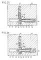
- the deviceIn the normal storage position, the device is in the position shown in FIG. 25, the green ball 64 being visible through a window 69 , which indicates that the storage temperature has been reached.
- the springexpands and moves the piston forward, this movement passing the first red ball 65 into the compartment 63 , where this ball can be viewed by a window 70 .
- a red ballis brought into compartment 63 , which allows the user to directly view the number of temperature overruns.
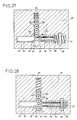
- Figures 27 to 30show a first variant of the device described with reference to Figures 24 to 26, in which the same elements are designated by the same references as above.
- This devicehas an additional originality by the presence of a window 76 . Its operation is identical, only indications are obtained additionally by the presence of this window 76 .
- the deviceAt ambient temperature, the device is in the state shown in FIG. 27, the five balls are housed in the chamber 62 , and the latter is closed by the rod 59 . Through the window 76, only the spring 57 is visible.
- the springcontracts, allowing a retraction of the piston, which opens the chamber 62 and under the action of expansion of the spring 67 housed in the latter, the advancement of the balls, the green ball falling into compartment 66 , and the first red ball coming opposite the piston 59 .
- the tongues 68formed in the crossing zones of the chambers 56 and 62, prevent disorderly displacements of the balls, at the unwanted temperatures.
- the deviceIn the normal storage position, the device is in the position shown in FIG. 28, the green ball 64 being visible through a window 69 and the support of the piston 58 also being visible through the window 76 . These two signals indicate that the storage temperature has been reached during the first temperature drop.
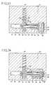
- the shape memory alloy springrelaxes and moves the piston forward, this movement passing the first red ball 65 into the compartment 63 , where this ball can be viewed by a window 70 .
- the support of the piston 58is no longer visible in the new window 76 , as shown in FIG. 29.
- the rise in temperaturemay not be sufficient to pass the critical threshold prefixed, so that the red ball is not ejected, the memory spring not being sufficiently relaxed. This possibility will be highlighted by this device because the support of the piston 58 will no longer be visible in the window 76 .
- FIG. 30shows the first drop in temperature following an untimely rise in temperature described in FIG. 29.
- the support of the piston 58is again visible in the new window 76 . If it is not visible and the device is in the configuration of FIG. 30 (a red ball ejected), this means that the temperature is higher than the storage temperature.
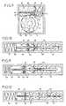
- Figures 31 to 34show a second variant of the device described above with reference to Figures 24 to 26. Compared to it it has an originality by the presence of a large window 77 disposed in the zone of movement of the spring 57 in memory alloy of form and which happens to be graduated linearly 78, (a, b, c, d); operation is identical to that of the previous device with additional indications. At room temperature (FIG. 31) facing the graduated window 77 , only the spring 57 is visible.
- the deviceWhen lowering to the set temperature, the device is in the position shown in FIG. 32, the green ball 64 being visible through a window 69 and the support of the piston 58 also being visible through the window 77 and opposite one of the graduations 78 b.
- This devicecomprises a box 81 of generally parallelepiped shape, in which an elongated chamber 94 is formed.
- this chambercontains a spring 92 of shape memory alloy, one end of which is secured to the bottom of the chamber, and the other end of which bears against the head of a piston 93 secured to 'a rod 88.
- a balancing spring 87On this piston 93 is supported a balancing spring 87 whose presence is optional.
- Room 94includes a second part separated from the other by a baffle 86 .
- clockwork mechanism 85, 89coupled to a tachometer mechanism 84 , the triggers of which operate using specific pushers 83, 91 actuating a switch 82, 90 .
- the deviceAt ambient temperature, the device is in the state shown in FIG. 35, the shape memory spring 92 is relaxed and the piston and its rod 93 occupy the entire left end of the elongated chamber 94 .
- the balancing spring 87is compressed between the baffle 86 and the support of the piston 93 .
- the switch 90Due to the absence of the support of the piston 93 under the pusher 91 , the switch 90 is not engaged, the clockwork movement 89 of the set temperature (storage) indicates a zero duration and the number of passages at this storage temperature is also zero at the turn count 84 a .
- the movements watch 85indicate a zero duration and the number of passages is zero for each round-accounts 84 b and 84 c.
- the deviceis therefore new, armed, no clock mechanism does not work.
- Figure 36shows this operation.
- the end of the pistonis located in the window 95 at a straight end whose graduation 96 indicates - 20 ° C, or a lower temperature such as - 25 ° C.
- Permanentlycan be read the temperature at which the device is located by the position of the left end of the piston rod with regard to the graduation 96 of window 95 .
- the clock mechanismscan be either mechanical (at all temperatures from - 150 ° C to + 130 ° C), or electronic (at temperatures between - 30 ° C and + 60 ° C).
- a variant of this systemmay consist of two graduated windows 95 96 of smaller sizes, located at each end of the chamber 94 with regard to the clockwork mechanisms.
- FIG. 38represents a rotary actuator making it possible to obtain both a longitudinal movement, of the spring type, and a rotary movement, without having to resort to a complex device for setting in rotation.
- This actuatorcomprises a structure in the general shape of a sphere delimited by elements in shape memory alloy 97 , produced from flat wires, blades or springs. At its end 98, the sphere is integral with the frame while its other end 99 is free.
- a central spring 100is associated with the sphere, which is strong enough to flatten the latter in the martensitic phase, but too weak to retain it in the austenitic phase.
- This deviceis capable of actuating a warning system or driving a rotating system composed only of free wheels, without using a pinion-rack torque.
- the central spring 100is not compulsory if the elements in shape memory alloy are educated in a double direction, at high and at low temperature.
- the means of transmitting informationcan be similar to those described in the previous embodiments.
- the fact of using several elements in shape memory alloymakes it possible to have a very efficient system.
- shape memory elementshaving an operation with hysteresis or without hysteresis.
- the inventionbrings a great improvement to the existing technique, by providing a device for monitoring the temperature of a product or an article, and for detecting a temperature overshoot, with immediate display of an overshoot and accounting for the number of overshoots.
- the means making it possible to introduce thermal inertia into the operation of the springcould be different, and constituted for example by a cylinder inside which the spring would be mounted, without however leaving the part of the invention.
Landscapes
- Physics & Mathematics (AREA)
- General Physics & Mathematics (AREA)
- Measuring Temperature Or Quantity Of Heat (AREA)
- Semiconductor Memories (AREA)
- Dram (AREA)
- Oscillators With Electromechanical Resonators (AREA)
- Displays For Variable Information UsingMovable Means (AREA)
- Temperature-Responsive Valves (AREA)
- Display Devices Of Pinball Game Machines (AREA)
- Devices For Indicating Variable Information By Combining Individual Elements (AREA)
Abstract
Description
Translated fromFrenchLa présente invention a pour objet un dispositif pour le contrôle de températures contenant au moins un élément en alliage à mémoire de forme.The present invention relates to a device for controlling temperatures containing at least one element in shape memory alloy.
Dans de nombreux domaines, il est indispensable d'enregistrer les variations de températures auxquelles est soumis un produit, une variation ou plusieurs variations selon les cas, ou le dépassement de températures prédéterminées pouvant rendre le produit impropre à une utilisation postérieure.In many fields, it is essential to record the variations in temperature to which a product is subjected, a variation or several variations as the case may be, or the exceeding of predetermined temperatures which can make the product unsuitable for later use.
Un exemple courant concerne le domaine alimentaire, dans lequel il convient de suivre la qualité du froid des denrées périssables : produits frais, surgelés, congelés, ou aliments devant être maintenus à une certaine température.A common example concerns the food sector, in which the quality of the cold of perishable foodstuffs should be monitored: fresh, frozen, frozen products or foods which must be kept at a certain temperature.
Or, il n'est pas exceptionnel qu'au cours des différentes manipulations auxquelles ils sont soumis, de tels produits dépassent une température prédéterminée au-dessus de laquelle ils peuvent subir des dommages.However, it is not exceptional that during the various manipulations to which they are subjected, such products exceed a predetermined temperature above which they may suffer damage.
Il est également important de suivre la qualité du froid fourni par des appareils de fabrication ou de conservation du froid tels que réfrigérateurs ou congélateurs, un défaut de fonctionnement pouvant se traduire par une remontée en température dommageable pour les produits qu'ils contiennent.It is also important to monitor the quality of the cold supplied by cold manufacturing or storage devices such as refrigerators or freezers, a malfunction which can result in a rise in temperature which is harmful to the products they contain.
Il convient également d'assurer un suivi en qualité des procédés de stérilisation, tant au niveau des produits stérilisés que des appareils de stérilisation.Quality monitoring of sterilization processes should also be ensured, both in terms of sterilized products and sterilization devices.
Dans le domaine de la santé, il convient de suivre les conditions de conservation du sang ou des produits dérivés du sang, de produits biologiques, biogénétiques ou de certains produits pharmaceutiques nécessitant le respect de températures strictes.In the field of health, the conditions for the storage of blood or blood products, biological, biogenetic or certain pharmaceutical products requiring compliance with strict temperatures should be followed.
Dans le domaine médical, il convient également d'assurer le suivi des organes de transplantation ainsi que des gamètes animales ou humaines.In the medical field, it is also necessary to ensure the monitoring of transplant organs as well as animal or human gametes.
Dans le domaine industriel, il est également souhaitable de contrôler la température de fonctionnement de certaines pièces de machines, la température de fabrication de certains composants, notamment des composants électroniques, ainsi que la température de stockage de divers matériaux : matériaux composites ou émulsions photographiques, par exemple.In the industrial field, it is also desirable to control the operating temperature of certain machine parts, the manufacturing temperature of certain components, in particular electronic components, as well as the storage temperature of various materials: composite materials or photographic emulsions, for example.
De plus, dans le domaine industriel, les variations de températures s'accompagnent, dans certains cas, de variations de pression qu'il est nécessaire de suivre. Par exemple, des canalisations sous pression suivies à l'aide de vannes instrumentées.In addition, in the industrial field, temperature variations are accompanied, in certain cases, by pressure variations which it is necessary to monitor. For example, pressurized lines followed using instrumented valves.
Il est donc important de disposer d'un dispositif simple et fiable qui puisse être attaché au produit et/ou aux machines, et puisse indiquer, par lecture directe, le dépassement d'une température déterminée.It is therefore important to have a simple and reliable device which can be attached to the product and / or to the machines, and which can indicate, by direct reading, that a determined temperature has been exceeded.
Le brevet français n° 2 560 992 au nom de la Demanderesse concerne un dispositif dans lequel le dépassement d'une température déterminée est indiqué par une coloration irréversible déclenchée à l'aide d'un élément réalisé en un alliage à mémoire de forme.French Patent No. 2,560,992 in the name of the Applicant relates to a device in which the exceeding of a determined temperature is indicated by an irreversible coloring triggered using an element made of a shape memory alloy.
Le but de la présente invention est de fournir un dispositif en alliage à mémoire de forme permettant un contrôle de températures :
- susceptible de détecter plusieurs dépassements de températures tout en mémorisant le nombre des dépassements,
- susceptible d'avoir un temps de réponse ("temps de retardement") variable sur chacun des seuils de température, ce qui n'est pas le cas actuellement pour tous les dispositifs, y compris celui du brevet
français n⁰ 2 560 992, - comportant un système inviolable d'affichage de chacun des seuils de températures,
- fonctionnant dans toutes les positions,
- résistant aux chocs, aux vibrations, aux rayonnements et à la corrosion,
- fabriquable et stockable à température ambiante, quelles que soient les températures d'utilisation, et
- s'activant de lui-même par passage des différents seuils de température.
- likely to detect several temperature exceedances while memorizing the number of exceedances,
- likely to have a variable response time ("delay time") on each of the temperature thresholds, which is not currently the case for all the devices, including that of French patent No. 2,560,992,
- comprising an inviolable system for displaying each of the temperature thresholds,
- operating in all positions,
- resistant to shock, vibration, radiation and corrosion,
- can be manufactured and stored at room temperature, whatever the temperatures of use, and
- activating itself by passing the different temperature thresholds.
A cet effet, le dispositif qu'elle concerne comprend un boîtier en matière synthétique contenant un élément moteur réalisé en au moins un alliage à mémoire de forme, auquel est associé un élément de transmission du mouvement constitué par un piston et une tige qui agit sur au moins un élément de signalisation enregistrant, de façon irréversible, le dépassement d'une température prédéterminée, le boîtier comportant des fenêtres transparentes permettant la visualisation de l'état du ou des éléments de signalisation.To this end, the device which it relates comprises a plastic casing containing a motor element made of at least one shape memory alloy, with which is associated a movement transmission element constituted by a piston and a rod which acts on at least one signaling element recording, irreversibly, the exceeding of a predetermined temperature, the housing comprising transparent windows allowing the display of the state of the or signaling elements.
L'élément moteur fait appel à un matériau en alliage à mémoire de forme de type connu, par exemple de type cuivre-nickel-aluminium, cuivre-zinc-aluminium, ou titane-nickel, ou encore peut être constitué par d'autres alliages ternaires ou quaternaires.The drive element uses a material of known shape memory alloy, for example of copper-nickel-aluminum, copper-zinc-aluminum, or titanium-nickel type, or may also be made of other alloys. ternary or quaternary.
De toute façon, l'invention sera bien comprise à l'aide de la description qui suit, en référence au dessin schématique annexé représentant plusieurs formes d'exécution de ce dispositif destiné au contrôle de franchissement de seuils de température :
- Figures 1 à 3 sont trois vues en coupe longitudinale d'un premier dispositif au cours de trois phases de fonctionnement ;
- Figures 4 à 6 sont trois vues en coupe longitudinale d'un second dispositif au cours de trois phases de fonctionnement ;
- Figures 7 à 9 sont trois vues d'un troisième dispositif pivotant au cours de trois phases de fonctionnement ;
- Figures 10 à 12 sont trois vues en coupe longitudinale d'un premier dispositif à déplacement linéaire au cours de trois phases de fonctionnement;
- Figures 13 à 15 sont trois vues en coupe longitudinale d'un second dispositif à déplacement linéaire au cours de trois phases de fonctionnement;
- Figures 16 et 17 sont deux vues en coupe longitudinale d'une variante d'exécution du dispositif des figures 13 à 15 ;
- Figure 18 est une vue de l'extérieur du boîtier d'un dispositif correspondant à l'une des formes d'exécution des figures 13 à 17 ;
- Figure 19 représente une seconde variante d'exécution du dispositif de figures 13 à 15 ;
- Figures 20 à 23 représentent une variante d'exécution du dispositif de figure 19 avec introduction d'éléments augmentant l'inertie thermique ;
- Figures 24 à 26 sont trois vues en coupe d'un autre dispositif ;
- Figures 27 à 30 sont quatre vues en coupe d'une première variante du dispositif représenté aux figures 24 à 26 ;
- Figures 31 à 34 sont quatre vues en coupe d'une seconde variante du dispositif représenté aux figures 24 à 26 ;
- Figures 35 à 37 représentent trois vues en coupe d'un dispositif permettant d'indiquer les durées de dépassement des différents seuils de températures préfixés ;
- Figure 38 représente un actionneur rotatif à mémoire de forme.
- Figures 1 to 3 are three views in longitudinal section of a first device during three operating phases;
- Figures 4 to 6 are three views in longitudinal section of a second device during three operating phases;
- Figures 7 to 9 are three views of a third device pivoting during three operating phases;
- Figures 10 to 12 are three views in longitudinal section of a first linear displacement device during three operating phases;
- Figures 13 to 15 are three views in longitudinal section of a second linear displacement device during three operating phases;
- Figures 16 and 17 are two views in longitudinal section of an alternative embodiment of the device of Figures 13 to 15;
- Figure 18 is a view of the exterior of the housing of a device corresponding to one of the embodiments of Figures 13 to 17;
- Figure 19 shows a second alternative embodiment of the device of Figures 13 to 15;
- Figures 20 to 23 show an alternative embodiment of the device of Figure 19 with the introduction of elements increasing the thermal inertia;
- Figures 24 to 26 are three sectional views of another device;
- Figures 27 to 30 are four sectional views of a first variant of the device shown in Figures 24 to 26;
- Figures 31 to 34 are four sectional views of a second variant of the device shown in Figures 24 to 26;
- Figures 35 to 37 show three sectional views of a device allowing to indicate the durations of exceeding the different preset temperature thresholds;
- Figure 38 shows a rotary actuator with shape memory.
Le dispositif, représenté aux figures 1 à 3, comprend un boîtier2 de forme générale parallélépipèdique dans lequel est montée pivotante autour d'un axe3 une roue4 sur la périphérie de laquelle sont régulièrement réparties des dents5.The device, shown in FIGS. 1 to 3, comprises a
Comme cela ressort du dessin, les dents5 sont orientées vers l'arrière par rapport au sens de rotation de la roue. Cette roue ne peut tourner que dans un sens, une languette élastique6 formant un cliquet anti-retour prenant appui, pour chaque position angulaire stable de la roue, dans le fond de l'évidement ménagé en arrière d'une dent5, empêchant ainsi la rotation de la roue dans le sens des aiguilles d'une montre.As can be seen from the drawing, the
Ce dispositif comprend un ressort7 en alliage à mémoire de forme, monté dans un cylindre8 d'axe sensiblement tangent à la circonférence de la roue, dont une extrémité est fixée contre le fond du boîtier et dont l'autre extrémité est fixée sur un piston9 monté coulissant dans le cylindre8, et de l'autre face duquel fait saillie une tige10 dont l'extrémité libre est équipée d'une lame métallique12 précontrainte en direction de l'axe3 de la roue, et destinée à venir prendre appui dans l'évidement disposé en arrière d'une dent5 de la roue4.This device comprises a spring7 made of shape memory alloy, mounted in a
Comme montré aux figures 1 à 3, la roue4 comporte, en regard de chaque dent5, un repère13 constitué, dans le cas présent, par un chiffre. Chaque repère13 est visible à travers une fenêtre transparente14, lorsqu'il se trouve en regard de ladite fenêtre. Enfin, la roue4 comporte un doigt15 faisant saillie latéralement destiné, lorsque la roue a pivoté de moins d'un tour, à venir prendre appui contre une butée16 solidaire du boîtier, pour éviter plusieurs passages successifs des mêmes repères13 en regard de la fenêtre14. Il est à noter que la distance entre deux dents5 adjacentes de la roue correspond à la course du ressort7 au cours d'une déformation de celui-ci.As shown in Figures 1 to 3, the
Le fonctionnement de ce dispositif est le suivant :
A température ambiante, le ressort7 est allongé comme montré à la figure 1, le piston9 se trouvant en position haute, et la lame métallique12 étant insérée dans l'évidement situé en arrière de la dent portant la référence (2). La fenêtre14, de même qu'une fenêtre17 située sur le parcours du ressort, ne laisse apparaître aucun signe distinctif particulier.The operation of this device is as follows:
At room temperature, the spring7 is elongated as shown in FIG. 1, the
Lorsque la température du boîtier est abaissée à la température de stockage du produit à contrôler, le ressort7 se contracte jusqu'à ce que ses spires soient sensiblement jointives, entraînant dans sa course le piston9 qui vient se positionner en regard de la fenêtre17, et la lame métallique12 dont l'extrémité vient se loger dans l'évidement situé en arrière de la dent référencée (3).When the temperature of the housing is lowered to the storage temperature of the product to be checked, the spring7 contracts until its turns are substantially contiguous, driving in its stroke the
Le fait pour l'utilisateur de visualiser le piston9 à travers la fenêtre permet de savoir que le produit et le dispositif qui lui est associé sont bien à la température de conservation choisie.The fact for the user to view the
Lors d'une remontée de température au-dessus d'un seuil pré-déterminé, le ressort7 retrouve sa configuration allongée, comme montré à la figure 3, la lame métallique12 entraînant, au cours de la détente du ressort, la roue4 en rotation dans le sens inverse des aiguilles d'une montre, la fin de rotation étant telle que la fenêtre14 laisse apparaître la dent portant la référence (1). Simultanément, le piston9 disparaît de la fenêtre17, ce qui signifie que la température normale de stockage a été dépassée, et que cette remontée en température continue puisque le piston n'est pas visible dans le repère17.During a rise in temperature above a predetermined threshold, the spring7 returns to its elongated configuration, as shown in FIG. 3, the
Lors d'une nouvelle descente en température, le ressort se contracte et le piston9 se retrouve visible à travers la fenêtre, signifiant que l'on a retrouvé la température de stockage, l'information fournie dans la fenêtre14 indiquant toutefois que le produit a subi un dépassement du seuil normal de température. Il est ainsi possible de visualiser immédiatement le nombre de dépassements de température, ce nombre pouvant être au plus égal au nombre de dents de la roue, puisque celle-ci se trouve nécessairement immobilisée en rotation par appui du doigt15 contre la butée16, plusieurs rotations successives de la roue ne pouvant, en effet, permettre de comptabiliser un nombre exact de dépassements de température.When the temperature drops again, the spring contracts and the
Il est possible d'associer plusieurs roues de diamètres différents (voir figure 3), qui s'actionnent successivement lorsque la roue de taille supérieure a fait un tour ; ainsi, il y a un nombre supérieur de dépassements de température qui peut être détecté.It is possible to combine several wheels of different diameters (see FIG. 3), which are actuated successively when the wheel of larger size has made a revolution; thus, there is a higher number of temperature overruns that can be detected.
Les figures 4 à 6 représentent un dispositif similaire au précédent, c'est-à-dire comportant une roue crantée, dans lequel les mêmes éléments sont désignés par les mêmes références que précédemment.Figures 4 to 6 show a device similar to the previous one, that is to say comprising a toothed wheel, in which the same elements are designated by the same references as above.
Dans ce nouveau dispositif, la roue dentée4 est équipée, dans un plan parallèle à celui comportant les dents, d'un nombre égal de godets18 occupant la même répartition angulaire et débouchant vers l'extérieur. Un magasin19 contenant des billes20 est monté de façon adjacente au cylindre8 contenant le ressort7 en alliage à mémoire de forne, les axes respectivement du cylindre8 et du magasin20 étant perpendiculaires. L'ouverture du magasin19 est obturable par un tiroir22, déplaçable par la tige10 associée au piston9. La taille des godets18 est telle que chacun d'entre eux puisse recevoir une bille20, chaque bille étant retenue dans le godet qu'elle est susceptible de remplir par des languettes élastiques23 disposées au bord du godet.In this new device, the
Le fonctionnement de ce dispositif est le suivant :
A la température ambiante et comme montré à la figure 4, les billes20 sont bloquées dans le magasin19 par le tiroir22. Lorsque la température descend jusqu'à la valeur de stockage, le ressort7 se comprime, entraînant dans sa course la tige10 et le tiroir22 qui ouvre le magesin19. La première bille, qui peut être par exemple une bille de couleur verte, est poussée par les billes suivantes, qui sont soumises à l'àction d'un ressort24, dans le premier godet18. Lors d'une remontée en température au-dessus d'un seuil prédéterminé, le ressort retrouve sa forme allongée et actionne, par l'intermédiaire de la tige10 et de la lame métallique12, la roue4 en rotation, le tiroir22 n'étant pas déplacé.The operation of this device is as follows:
At room temperature and as shown in FIG. 4, the
Au cours de cette rotation, un nouveau godet18 vient en regard du magasin19, permettant la réception d'une bille20 qui peut être une bille rouge traduisant le dépassement de la température de seuil. Une nouvelle descente en température permet une recompression du ressort. La transparence de la partie supérieure du boîtier, ou tout au moins de la zone de celui-ci située en regard du parcours du godet, permet de visualiser immédiatement le nombre de dépassements de la température de seuil.During this rotation, a
Les figures 7 à 9 représentent un autre dispositif similaire aux précédents, c'est-à-dire comportant une roue crantée entraînable en rotation lors de chaque dépassement de température, dans lequel les mêmes éléments sont désignés par les mêmes références que précédemment. Dans ce cas, à la roue crantée sont associés des godets25 situés chacun en regard d'une dent5 de la roue, ces godets comportant chacun un clapet de fermeture26.Figures 7 to 9 show another device similar to the previous ones, that is to say comprising a toothed wheel which can be driven in rotation at each temperature overshoot, in which the same elements are designated by the same references as above. In this case, the notched wheel is associated with
Dans cette forme d'exécution, un réservoir27 contenant un fluide tel que de la poudre, du sable ou un liquide visqueux, est monté adjacent au cylindre8 contenant le ressort7. Le fluide est susceptible de s'écouler hors du réservoir par une ouverture28 sous l'action de la pression exercée par un piston29 et un ressort30. Un tiroir32 comportant lui-même une ouverture33 est solidaire de la tige10, l'ouverture33 étant positionnée de façon telle qu'elle se trouve en regard de l'ouverture32 du réservoir lorsque le ressort7 est en position détendue.In this embodiment, a
A température ambiante, représentée à la figure 7, les ouvertures32 et33 se trouvant en regard, le premier godet25 se remplit de fluide. Lorsque le dispositif descend en température, en dessous d'une valeur prédéterminée, le ressort7 se comprime, le tiroir32 assurant alors la fermeture du réservoir27, comme montré à la figure 8. Lors d'un dépassement de la température de seuil, le ressort7 se détend, ce qui assure, d'une part, la rotation de la roue4 et l'amenée d'un nouveau godet en regard de l'ouverture32 du réservoir et, d'autre part, la mise en communication de cette ouverture32 avec l'ouverture33 du tiroir. Ce godet se remplit jusqu'à ce que la température redescende, la quantité de fluide contenue dans le godet permettant de déterminer non seulement l'existence d'un dépassement de température, mais également d'estimer la durée de ce dépassement, lorsque l'on connaît le débit d'écoulement du fluide hors du réservoir.At ambient temperature, shown in FIG. 7, the
Il serait possible de disposer d'un appareil plus élaboré comprenant un second moteur en alliage à mémoire de forme, fermant le tiroir ou les clapets, dès que la température de seuil est franchie en sens inverse, de façon à indiquer le temps de dépassement du seuil.It would be possible to have a more elaborate device comprising a second shape memory alloy motor, closing the drawer or the flaps, as soon as the threshold temperature is crossed in the opposite direction, so as to indicate the time for exceeding the threshold.
Le dispositif, représenté aux figures 10 à 12, est un dispositif à fonctionnement linéaire, comportant un corps allongé34, par exemple de forme cylindrique. A l'une des extrémités du boîtier34 est monté, à l'intérieur de celui-ci, un ressort35 en alliage à mémoire de forme, dont une extrémité est fixée contre le fond du boîtier et dont l'autre extrémité est fixée sur un piston36 solidaire d'une tige37 s'étendant dans le sens de la longueur du boîtier. Sur cette tige37 est montée un curseur38 présentant une ouverture centrale et dont le corps est profilé, c'est-à-dire dont la paroi latérale s'étend depuis la tige vers l'extérieur, et de l'extrémité du boîtier opposée à celle équipée du ressort, vers celle comportant le ressort. La tige est équipée de crans39 profilés en sens inverse du curseur, pour permettre un déplacement relatif par rapport au curseur, seulement en direction du ressort35. Pour sa part, le boîtier comporte, sur sa face interne, des crans40 constitués par une succession de surfaces inclinées et de surfaces perpendiculaires à la tige37, permettant seulement le déplacement du curseur, de l'extrémité du boîtier comportant le ressort vers son extrémité opposée. La tige37 porte également, du côté du piston36, un épaulement42 destiné à coopérer avec un anneau43 monté libre sur la tige, entre le piston36 et lui-même. A proximité de son extrémité située du côté du piston36, le boîtier34 comporte un logement44 disposé en regard d'une fenêtre, non représentée au dessin. Il est à noter que la course du ressort35 au cours d'un cycle de déformation, correspond sensiblement au pas des crans40 du boîtier.The device, shown in Figures 10 to 12, is a linear operation device, comprising an
Le fonctionnement de ce dispositif est le suivant :
A température ambiante et avant première utilisation, le dispositif se trouve dans l'état représenté à la figure 10. Lorsque la température est abaissée jusqu'à la valeur de stockage, le ressort35 se comprime, entraînant dans son mouvement le piston36, la tige37 et l'épaulement42. Ce dernier fait passer l'anneau43 dans le logement44 ce qui permet de visualiser instantanément la descente à la température de stockage. Il est à noter qu'au cours de ce mouvement, et comme montré à la figure 11, le curseur38 n'a pas bougé, puisqu'il est demeuré bloqué par le cran40, contre lequel il était en appui, tout en permettant le passage d'un cran anti-retour39 de la tige37 dans son ouverture centrale.The operation of this device is as follows:
At room temperature and before first use, the device is in the state shown in FIG. 10. When the temperature is lowered to the storage value, the
Lors d'une montée en température, au-dessus de la valeur de seuil, le ressort35 se détend, assurant le déplacement vers la droite du piston36 et de la tige37. Un cran39 en appui contre le curseur38 déplace celui-ci vers la droite pour l'amener en position de blocage dans le cran anti-retour40 suivant.During a rise in temperature, above the threshold value, the
Il est ainsi possible de visualiser immédiatement le nombre de dépassements de la température du seuil, en comptabilisant le nombre de crans40, qui ont été parcourus par le curseur38. Ceci est rendu possible en ménageant une fenêtre dans le corps du boîtier sur le parcours du curseur38, et en portant des graduations le long de cette fenêtre:It is thus possible to immediately display the number of exceedances of the threshold temperature, by counting the number of
Les figures 13 à 15 représentent une variante d'exécution du dispositif de figures 10 à 12, dans laquelle les mêmes éléments sont désignés par les mêmes références que précédemment.Figures 13 to 15 show an alternative embodiment of the device of Figures 10 to 12, in which the same elements are designated by the same references as above.
Dans ce cas, le ressort35, en alliage à mémoire de forme, est fixé non pas contre le fond du boîtier, mais contre le fond d'un second curseur45 jouant le rôle du piston36 décrit précédemment, le ressort35 prenant appui directement sur le curseur38. Ce curseur38 est traversé par la tige37 solidaire du curseur45, dont l'extrémité libre comporte un épaulement46 servant à l'appui d'un ressort d'équilibrage47 dont l'autre extrémité est en appui contre le curseur38. Lorsque le dispositif est à température ambiante, comme montré à la figure 13, le ressort35 est détendu et les deux curseurs38 et45 sont séparés par trois crans40 du boîtier34. Lorsque le dispositif descend en température et que la température de stockage est atteinte, le ressort se comprime. Le curseur38 étant bloqué contre un cran40, le curseur45 accompagne le ressort dans son mouvement, de telle sorte qu'en fin de compression, les deux curseurs se trouvent placés sur des crans voisins, comme montré à la figure 14. Une fenêtre, non représentée au dessin, permet de visualiser la position des deux curseurs. Si, lors d'une remontée en température, la température de seuil est atteinte, puis dépassée, le ressort35 s'allonge, le curseur45 étant bloqué contre le cran40 au contact duquel il se trouve, seul le curseur38 peut accompagner le mouvement du ressort et se déplacer d'un cran. Si la température continue d'augmenter, le curseur38 peut continuer à se déplacer compte tenu de l'allongement correspondant du ressort35.In this case, the
La présence du ressort d'équilibrage47 permet d'éviter de solidariser l'extrémité du ressort35 et le curseur38, et de compenser les phénomènes d'hystérésis liés au fonctionnement d'un ressort en alliage à mémoire de forme.The presence of the balancing
Dans la mesure où le ressort35 est fixé à ses deux extrémités, respectivement, sur le curseur38 et sur le curseur45, et dans la mesure où il ne présente pas de phénomène d'hystérésis, il est possible de se dispenser du ressort d'équilibrage47.Insofar as the
Le dispositif se présente alors sous la forme simplifiée représentée aux figures 16 à 17 où le ressort se trouve, respectivement, en position détendue et en position comprimée.The device is then presented in the simplified form shown in Figures 16 to 17 where the spring is, respectively, in the relaxed position and in the compressed position.
La figure 18 représente très schématiquement l'extérieur d'un boîtier et, plus spécialement, les séries de fenêtres ménagées dans celui-ci. Ces fenêtres référencées48 et49 sont groupées par paire, à l'exception, à l'extrême droite, de la fenêtre41 dans laquelle le curseur45 se trouve et qui correspond à la température normale de fabrication (température ambiante). A la température de fabrication, le curseur45 est dans la fenêtre41, tandis que le curseur38 est dans la fenêtre49. A la température normale de stockage (basse température), le curseur45 est passé dans la fenêtre48, tandis que le curseur38 est passé dans la fenêtre49. Après un premier dépassement de température au-dessus de la température de stockage, le curseur45 est passé dans la fenêtre48, tandis que le curseur38 est resté dans la fenêtre49l. Lors du retour à la température basse de stockage, le curseur45 passe dans la fenêtre48l.FIG. 18 very schematically represents the exterior of a housing and, more specifically, the series of windows formed therein. These windows referenced48 and49 are grouped in pairs, with the exception, on the far right, of
Ainsi, les indicesi des fenêtres48i et49i indiquent le nombre de dépassements de la température de stockage et, selon la position du curseur45, le retour ou non à la température de stockage après leième dépassement.Thus, the indicesi of the
Selon l'épaisseur du boîtier34, il y aura un temps de retard au dépassement en températures plus ou moins important : de quelques minutes à plusieurs heures, selon la demande de l'utilisateur lors de la fabrication du dispositif.Depending on the thickness of the
Il est possible de modifier le boîtier au niveau de la position des fenêtres49i par rapport à48i et de suivre le couple45-46 (au lieu de45-38) dans ses mouvements respectifs.It is possible to modify the housing at the position of the
Il est intéressant de disposer de curseurs de couleurs différentes : le45 en vert et le (ou les)38 (et46) en rouge, par exemple. Ainsi l'utilisateur poura conclure immédiatement aux dépassements de la température normale de stockage.It is interesting to have sliders of different colors: the45 in green and the (or)38 (and46 ) in red, for example. Thus the user can immediately conclude that the normal storage temperature has been exceeded.
La figure 19 représente une variante d'exécution des dispositifs précédents, dans laquelle les deux curseurs38 et45 ne sont plus reliés l'un à l'autre par une tige coulissante à travers le curseur38 mais seulement par le ressort35, en alliage en mémoire de forme. Il est à noter que le curseur38 peut lui-même être réalisé en un alliage à mémoire de forme, afin d'intervenir sur ces conditions de déplacement et de blocage dans les crans40, en fonction des températures de stockage et de seuil.FIG. 19 represents an alternative embodiment of the preceding devices, in which the two
Les figures 20 à 23 représentent une variante d'exécution du dispositif des figures 16, 17 et 19, dans laquelle sont prévus des moyens permettant de retarder la déformation de l'élément35 en alliage à mémoirede forme, lors du dépassement d'une température de seuil. A cet effet, le boîtier est muni, sur sa périphérie, d'un certain nombre d'éléments50 décalés axialement les uns par rapport aux autres, s'étendant chacun sur une longueur correspondant à trois crans, et dont la partie amont52, dans le sens de déplacement du ressort35, est inférieure à l'épaisseur de la partie aval53.Figures 20 to 23 show an alternative embodiment of the device of Figures 16, 17 and 19, in which are provided means for delaying the deformation of the
A température ambiante, le ressort35 se trouve en position allongée et les deux curseurs38 et45 sont séparés par trois crans. Ils délimitent avec le corps du boîtier une chambre54. La faible épaisseur du corps du boîtier permet une diffusion thermique rapide, de telle sorte que, lorsque la température descend jusqu'à la valeur de consigne, le ressort35 se contracte très rapidement jusqu'à ce que le curseur45 se trouve en appui contre un cran adjacent de celui contre lequel est en appui le curseur38. Dans cette position, le volume délimité entre les deux curseurs se trouve, comme montré à la figure 21, en regard de la partie52 de faible épaisseur du premier élément50. Lorsque la température dépasse la température de seuil, l'élément50, compte tenu de son inertie thermique, retarde le moment de réponse du ressort. Lorsque le ressort se détend, le curseur38 se déplace en même temps que celui-ci, comme montré aux figures 22 et 23.At room temperature, the
En jouant sur l'épaisseur de matière des éléments50, il est possible de régler le temps de réponse du ressort35 et, éventuellement, de disposer de plusieurs éléments de différentes épaisseurs pour introduire des inerties spécifiques aux différents dépassements.By varying the material thickness of the
Les figures 24 à 26 représentent un autre dispositif comportant un boîtier55 de forme générale parallélépipèdique, dans lequel sont ménagées deux chambres allongées perpendiculaires l'une à l'autre, et débouchant l'une dans l'autre. La première chambre56 contient, à l'une de ses extrémités, un ressort57 en alliage à mémoire de forme, dont une extrémité est solidaire du fond de la chambre, et dont une extrémité prend appui contre un piston58 solidaire d'une tige59. Sur le piston58 prend appui un ressort d'équilibrage60 dont la présence est facultative. La chambre56 s'étend de l'autre côté de sa zone de raccordement avec la chambre62, qui en est perpendiculaire, afin de former une zone63 de réception de billes. En effet, la partie principale de la chambre62 forme un réservoir pour plusieurs billes, au nombre de cinq dans la forme d'exécution représentée au dessin, dont la première64 est de couleur verte, et dont les autres65 sont de couleur rouge.Figures 24 to 26 show another device comprising a
Dans sa zone située au-delà de la chambre56, cette chambre62 délimite un compartiment66 permettant la réception d'une seule bille. La longueur de la tige59 est telle qu'en fonction de l'état du ressort57, elle obture ou non la chambre62.In its zone located beyond the
A température ambiante, le dispositif se trouve dans l'état représenté à la figure 24, les cinq billes sont logées dans la chambre62 et celle-ci est obturée par la tige59. Lors de la descente à la température de consigne, le ressort57 se contracte, permettant un recul du piston, qui ouvre la chambre62 et sous l'action de détente du ressort67 logé dans cette dernière, l'avancée des billes, la bille verte tombant dans le compartiment66, et la première bille rouge venant en regard du piston59.At room temperature, the device is in the state shown in FIG. 24, the five balls are housed in the
Il est à noter que des languettes68, ménagées dans les zones de croisement des chambres56 et62 évitent des déplacements désordonnés des billes, aux températures non désirées.It should be noted that the
En position de stockage normal, le dispositif se trouve dans la position représentée à la figure 25, la bille verte64 étant visible par une fenêtre69, ce qui indique que la température de stockage a bien été atteinte. Lors d'une remontée en température au-dessus de la température de consigne, le ressort se détend et déplace le piston vers l'avant, ce mouvement faisant passer la première bille rouge65 dans le compartiment63, où cette bille peut être visualisée par une fenêtre70. Au cours de chaque cycle suivant de descente et de remontée en température, une bille rouge est amenée dans le compartiment63, ce qui permet à l'utilisateur de visualiser directement le nombre de dépassements de température.In the normal storage position, the device is in the position shown in FIG. 25, the
Les figures 27 à 30 représentent une première variante du dispositif décrit en référence aux figures 24 à 26, dans laquelle les mêmes éléments sont désignés par les mêmes références que précédemment.Figures 27 to 30 show a first variant of the device described with reference to Figures 24 to 26, in which the same elements are designated by the same references as above.
Ce dispositif présente une originalité supplémentaire par la présence d'une fenêtre76. Son fonctionnement est identique, seules des indications sont obtenues de façon supplémentaire par la présence de cette fenêtre76. A température ambiante, le dispositif se trouve dans l'état représenté à la figure 27, les cinq billes sont logées dans la chambre62, et celle-ci est obturée par la tige59. Par la fenêtre 76, seul le ressort57 est visible. Lors de la descente de la température de consigne, le ressort se contracte, permettant un recul du piston, qui ouvre la chambre62 et sous l'action de détente du ressort67 logé dans cette dernière, l'avancée des billes, la bille verte tombant dans le compartiment66, et la première bille rouge venant en regard du piston59.This device has an additional originality by the presence of a
Il est à noter que des languettes68, ménagées dans les zones croisement des chambres56 et62 évitent des déplacements désordonnés des billes, aux températures non désirées.It should be noted that the
En position de stockage normal, le dispositif se trouve dans la position représentée à la figure 28, la bille verte64 étant visible par une fenêtre69 et l'appui du piston58 se trouvant lui aussi visible par la fenêtre76. Ces deux signaux indiquent que la température de stockage a bien été atteinte lors de la première descente en température.In the normal storage position, the device is in the position shown in FIG. 28, the
Lors d'une remontée en température au-dessus de la température de consigne, le ressort en alliage à mémoire de forme se détend et déplace le piston vers l'avant, ce mouvement faisant passer la première bille rouge65 dans le compartiment63, où cette bille peut être visualisée par une fenêtre70.When the temperature rises above the set temperature, the shape memory alloy spring relaxes and moves the piston forward, this movement passing the first
L'appui du piston58, quant à lui, n'est plus visible dans la nouvelle fenêtre76, comme montré à la figure 29. Cependant, il se peut que l'élévation de la température ne soit pas suffisante pour passer le seuil critique préfixé, donc que la bille rouge ne soit pas éjectée, le ressort à mémoire n'étant pas assez détendu. Cette possibilité sera mise en évidence par ce dispositif car l'appui du piston58 ne sera plus visible dans la fenêtre76.The support of the
Au cours de chaque cycle suivant de descente et de remontée en température, une bille rouge est amenée dans le compartiment63, ce qui permet à l'utilisateur de visualiser directement le nombre de dépassements de température.During each subsequent cycle of descent and rise in temperature, a red ball is brought into
La figure 30 présente la première descente en température consécutive à une remontée intempestive en température décrite à la figure 29. Lorsque la température de stockage est de nouveau atteinte, l'appui du piston58 est de nouveau visible dans la nouvelle fenêtre76. Si celui-ci n'est pas visible et que le dispositif est dans la configuration de la figure 30 (une bille rouge éjectée) cela signifie que la température est supérieure à la température de stockage.FIG. 30 shows the first drop in temperature following an untimely rise in temperature described in FIG. 29. When the storage temperature is again reached, the support of the
Les figures 31 à 34 représentent une seconde variante du dispositif décrit précédemment en référence aux figures 24 à 26. Par rapport à celui-ci il présente une originalité par la présence d'une grande fenêtre77 disposée dans la zone de débattement du ressort57 en alliage à mémoire de forme et qui se trouve être graduée linéairement78, (a,b,c,d) ; le fonctionnement est identique à celui du dispositif précédent avec des indications supplémentaires. A la température ambiante (figure 31) face à la fenêtre graduée77, seul est visible le ressort57.Figures 31 to 34 show a second variant of the device described above with reference to Figures 24 to 26. Compared to it it has an originality by the presence of a
Lors de la descente à la température de consigne, le dispositif se trouve dans la position représentée à la figure 32, la bille verte64 étant visible par une fenêtre69 et l'appui du piston58 se trouvant lui aussi visible par la fenêtre77 et en face d'une des graduations78 b.When lowering to the set temperature, the device is in the position shown in FIG. 32, the
Ces graduations linéaires correspondent pour un ressort en alliage à mémoire donnée57 à une série de températures.These linear graduations correspond for a memory alloy spring given to57 to a series of temperatures.
Ainsi par exemple dans ce cas :
- a = - 13° C
- b = - 16° C
- c = - 19° C
- d = - 22° C
- a = - 13 ° C
- b = - 16 ° C
- c = - 19 ° C
- d = - 22 ° C
Lors d'une remontée en température au-dessus de la température de consigne, ce qui est représenté à la figure 33, une bille rouge65 est éjectée dans le compartiment63 où elle est visualisée par la fenêtre70. L'appui du piston58 quant à lui, n'est plus visible dans la fenêtre77.When the temperature rises above the set temperature, which is shown in FIG. 33, a
Une variante avantageuse de ce dispositif, représentée à la figure 34, consiste à aggrandir suffisamment en largeur cette fenêtre graduée79 afin de déterminer instantanément quelle est la température entre par exemple :
- a = + 5° C
- b = 0° C
- c = - 5° C
- d = - 10° C
- e = - 15° C
- f = - 20° C
- g = - 25° C
- a = + 5 ° C
- b = 0 ° C
- c = - 5 ° C
- d = - 10 ° C
- e = - 15 ° C
- f = - 20 ° C
- g = - 25 ° C
Ce dispositif comprend un boîtier81 de forme générale parallélépipèdique, dans lequel est ménagée une chambre allongée94. Dans l'une de ses extrémités, cette chambre contient un ressort92 en alliage à mémoire de forme, dont une extrémité est solidaire du fond de la chambre, et dont l'autre extrémité prend appui contre la tête d'un piston93 solidaire d'une tige88. Sur ce piston93 prend appui un ressort d'équilibrage87 dont la présence est facultative. La chambre94 comprend une seconde partie séparée de l'autre par une chicane86. Dans chaque partie de cette chambre94 se trouve au moins un mécanisme d'horlogerie85, 89 couplé à un mécanisme de compte-tours84 dont les déclenchements s'opèrent à l'aide de poussoirs spécifiques83, 91 actionnant un interrupteur82, 90.This device comprises a
A la température ambiante, le dispositif se trouve dans l'état représenté à la figure 35, le ressort92 à mémoire de forme est détendu et le piston et sa tige93 occupent toute l'extrémité gauche de la chambre allongée94. Le ressort d'équilibrage87 se trouve comprimé entre la chicane86 et l'appui du piston93.At ambient temperature, the device is in the state shown in FIG. 35, the
Du fait de l'absence de l'appui du piston93 sous le poussoir91, l'interrupteur90 n'est pas enclenché, le mouvement d'horlogerie89 de la température de consigne (stockage) indique une durée nulle et le nombre de passages à cette température de stockage est aussi nul au compte tour84a.Due to the absence of the support of the
Malgré la présence de la tige du piston, dont l'extrémité dans la fenêtre graduée95, 96 indique la température ambiante (par exemple 20° C), sous les poussoirs83 des mécanismes d'horlogerie pour le dépassement des températures élevées, les mouvements d'horlogerie85 indiquent une durée nulle ainsi que le nombre de passages qui est nul pour chacun des comptes-tours84b et 84c.Despite the presence of the piston rod, the end of which in the graduated
Cela s'explique par la forme des poussoirs83 qui sont montés à l'inverse de celui décrit en91. Ainsi lors du montage du dispositif à la température ambiante, en usine, bien que la tige du piston soit en contact avec les poussoirs, ceux-ci ne peuvent déclencher les mécanismes d'horlogerie et les compte-tours.This is explained by the shape of the
Le dispositif est donc neuf, armé, aucun mécanisme d'horlogerie ne fonctionne.The device is therefore new, armed, no clock mechanism does not work.
Lors de la descente à la température de consigne le ressort à mémoire92 se contracte, permettant un recul du piston. L'appui du piston93 fait basculer le poussoir91 qui déclenche l'interrupteur90. Le mécanisme d'horlogerie pour la basse température (par exemple - 18° C) se met en marche, ainsi que le compte-tour84a qui indique 1.When lowering to the set temperature the
La figure 36 indique ce fonctionnement. L'extrémité du piston se trouve dans la fenêtre95 à une extrémité droite dont la graduation96 indique - 20° C, ou bien une température inférieure telle que - 25° C.Figure 36 shows this operation. The end of the piston is located in the
Ainsi en regardant le dispositif on sait :
- qu'il est pour une durée de x heures à au moins - 20° C, qu'il s'agit de son premier passage et qu'à l'instantt il est à - 25° C par exemple.
- that it is for a duration of x hours at least - 20 ° C, that it is his first pass and that at the instantt it is at - 25 ° C for example.
Quant aux mouvements d'horlogerie85 correspondant aux dépassements des températures élevées, ils indiquent toujours une durée nulle ainsi que le nombre de passages qui est nul pour chacun des compte-tours84b, 84c. Cela est dû à l'absence de la tige du piston sous chacun des poussoirs83, qui ne peuvent enclencher les interrupteurs82.As for the
En position de stockage, seul le mécanisme d'horlogerie pour la température de stockage fonctionne et son compte-tours indique1.In the storage position, only the clock mechanism for the storage temperature operates and its tachometer indicates1 .
Lors d'une remontée en température au-dessus de la température de consigne, comme montré à la figure 37, le ressort à mémoire92 se détend, déplace le piston vers l'avant, et ce mouvement selon son amplitude :
- arrête, par l'absence de la tête du piston sous le poussoir91 le mécanisme d'horlogerie de la température de stockage,
- déclenche au moins un des mécanismes d'horlogerie des températures élevées par la présence de la tige du piston sous le poussoir83 qui enclenche l'interrupteur82, le temps commence à être indiqué et le compte-tours marque1 (84b).
- stops, by the absence of the piston head under the
pusher 91, the storage temperature clock mechanism, - triggers at least one of the high temperature clock mechanisms by the presence of the piston rod under the
pusher 83 which activates theswitch 82 , the time begins to be indicated and the tachometer marks1 (84b).
Si l'amplitude de mouvement est plus importante (la température est plus élevée) la tige du piston enclenche le second poussoir83, le second mécanisme d'horlogerie se met en marche et le compte-tours84c marque1.If the amplitude of movement is greater (the temperature is higher) the piston rod engages the
En permanence peut être lue la température à laquelle se trouve le dispositif par la position de l'extrémité gauche de la tige du piston au regard de la graduation96 de la fenêtre95.Permanently can be read the temperature at which the device is located by the position of the left end of the piston rod with regard to the
Lors de la redescente en température de consigne, le ressort à mémoire se contractant, l'appui du piston93 fait de nouveau basculer le poussoir91 qui déclenche l'interrupteur90. Le mécanisme d'horlogerie pour la basse température se remet en marche, le compte tour84a indique2.During the descent to the set temperature, the memory spring contracting, the support of the
Lors d'une nouvelle remontée en température, c'est le ou les mécanismes d'horlogerie pour les températures élevées qui se remettent en marche, ainsi que le ou les compte-tours qui indiquent2.When the temperature rises again, it is the clock mechanism (s) for high temperatures which restart, as well as the rev counter (s) which indicate2.
Les mécanismes d'horlogerie peuvent être soit mécaniques (à toutes températures de - 150° C à + 130° C), soit électroniques (aux températures comprises entre - 30° C et + 60° C).The clock mechanisms can be either mechanical (at all temperatures from - 150 ° C to + 130 ° C), or electronic (at temperatures between - 30 ° C and + 60 ° C).
Le bon fonctionnement d'un tel système est contrôlable à tout moment, en effet :
- le nombre de dépassements pour chaque mécanisme aux températures élevées doit toujours être inférieur d'au moins1 à celui de la température de stockage par exemple :
nombre de tours à - 18° C = x
nombre de tours à - 5° C = x - 1 - le nombre de dépassements pour les mécanismes aux températures élevées doit suivre la règle suivante :
- the number of overshoots for each mechanism at high temperatures must always be at least1 lessthan that of the storage temperature, for example:
number of turns at - 18 ° C = x
number of turns at - 5 ° C = x - 1 - the number of overshoots for mechanisms at high temperatures must follow the following rule:
Ainsi, en regardant les mécanismes d'horlogerie et les comptetours associés, il est possible de vérifier par ces conditions, s'il y a une avarie dans le système de marquage (poussoir abîmé...).Thus, by looking at the clock mechanisms and the associated countertours, it is possible to check by these conditions, whether there is any damage in the marking system (damaged push-button ...).
A la place d'un mécanisme d'horlogerie aux températures de stockage et températures élevées, il est possible de mettre un système électronique enregistrant lorsque le poussoir est enclenché l'intégralité des données, dates de dépassement. Ce dernier dispositif est le plus sophistiqué.Instead of a clock mechanism at storage temperatures and high temperatures, it is possible to put an electronic system recording when the push-button is engaged all the data, dates of overrun. This last device is the most sophisticated.
Enfin, il est possible d'avoir un système tel que décrit à la figure 35 indiquant avec l'ajout d'un calendrier électronique les dates de dépassement de hautes températures.Finally, it is possible to have a system as described in Figure 35 indicating with the addition of an electronic calendar the dates when high temperatures are exceeded.
Une variante de ce système peut consister en deux fenêtres95 graduées96 de plus petites tailles, situées à chacune des extrémités de la chambre94 au regard des mécanismes d'horlogerie.A variant of this system may consist of two graduated
En prenant un piston93 dont l'appui soit de couleur verte et la tige de couleur rouge, on saurait à tout instant, en regardant la fenêtre de l'extrémité droite :
- si la couleur est verte : tout va bien et on regarde le mécanisme d'horlogerie, et en regardant la fenêtre de l'extrémité gauche :
- si la couleur est rouge : attention, il y a eu un dépassement de température et il convient de regarder le mécanisme d'horlogerie pour voir les durées de dépassement en température.
- if the color is green: everything is fine and we look at the clock mechanism, and looking at the window at the left end:
- if the color is red: be careful, there has been an overshoot and it is advisable to look at the clock mechanism to see the durations of overshoot in temperature.
La figure 38 représente un actionneur rotatif permettant d'obtenir à la fois un déplacement longitudinal, de type ressort, et un mouvement rotatif, sans avoir à recourir à un dispositif complexe de mise en rotation. Cet actionneur comprend une structure en forme générale de sphère délimitée par des éléments en alliage à mémoire de forme97, réalisés à partir de fils, lames ou ressorts plats. A son extrémité98, la sphère est solidaire du bâti alors que son autre extrémité99 est libre. Un ressort central100 est associé à la sphère, qui est suffisamment fort pour aplatir cette dernière en phase martensitique, mais trop faible pour la retenir en phase austénitique.FIG. 38 represents a rotary actuator making it possible to obtain both a longitudinal movement, of the spring type, and a rotary movement, without having to resort to a complex device for setting in rotation. This actuator comprises a structure in the general shape of a sphere delimited by elements in
Lors d'un refroidissement, les éléments tendent à se rétracter en vrillant, ce qui assure un rapprochement des deux extrémités fixe et mobile, avec un mouvement de rotation de l'extrémité mobile, qui peut aller jusqu'à 360°. Lors d'une montée en température, les éléments reprennent leur position précédente, assurant un déplacement axial et en rotation en sens inverse. Ce dispositif est susceptible d'actionner un système avertisseur ou d'entraîner un système en rotation composé uniquement de roues libres, sans utiliser de couple pignon-crémaillère.During cooling, the elements tend to retract while twisting, which ensures a bringing together of the fixed and mobile ends, with a movement of rotation of the mobile end, which can go up to 360 °. When the temperature rises, the elements return to their previous position, ensuring axial displacement and rotation in opposite directions. This device is capable of actuating a warning system or driving a rotating system composed only of free wheels, without using a pinion-rack torque.
Le ressort central100 n'est pas obligatoire si les éléments en alliage à mémoire de forme sont éduqués dans un double sens, à haute et à basse température. Les moyens de transmission de l'information peuvent être similaires à ceux décrits dans les formes d'exécution précédentes. Le fait d'utiliser plusieurs éléments en alliage à mémoire de forme permet de disposer d'un système très performant.The
Dans toutes les formes d'exécutions décrites précédemment, il est possible de mette en oeuvre des éléments à mémoire de forme présentant un fonctionnement avec hystérésis ou sans hystérésis.In all the forms of execution described above, it is possible to use shape memory elements having an operation with hysteresis or without hysteresis.
Dans toutes les formes d'exécution décrites précédemment, il est possible d'associer à l'élément ou aux éléments en alliage à mémoire un ou des ressorts permettant de modifier les températures de réaction du dispositif.In all of the embodiments described above, it is possible to associate the element or elements with memory alloy one or more springs making it possible to modify the reaction temperatures of the device.
Comme il ressort de ce qui précède, l'invention apporte une grande amélioration à la technique existante, en fournissant un dispositif de contrôle de la température d'un produit ou d'un article, et de détection d'un dépassement de température, avec visualisation immédiate d'un dépassement et comptabilisation du nombre de dépassements.As is apparent from the above, the invention brings a great improvement to the existing technique, by providing a device for monitoring the temperature of a product or an article, and for detecting a temperature overshoot, with immediate display of an overshoot and accounting for the number of overshoots.
C'est ainsi notamment que les moyens permettant d'introduire une inertie thermique dans le fonctionnement du ressort pourraient être différents, et constitués par exemple par un cylindre à l'intérieur duquel serait monté le ressort, sans que l'on sorte pour autant du cadre de l'invention.Thus, in particular, the means making it possible to introduce thermal inertia into the operation of the spring could be different, and constituted for example by a cylinder inside which the spring would be mounted, without however leaving the part of the invention.
Claims (31)
- Device for monitoring temperatures, characterised in that it comprises a casing (2, 34, 55) made of synthetic material, containing a drive component (7, 35, 57) made of at least one shape-memory alloy, with which is associated a movement-transmission component consisting of a piston (9, 36, 45, 58) and a rod (10, 37, 59), which acts on at least one indicator element (4, 20, 38, 65) registering irreversibly each occasion on which a predetermined temperature has been exceeded, the casing having transparent windows enabling the state of the indicator element or elements to be observed.
- Device according to Claim 1, characterised in that it comprises:. a wheel (4), mounted so as to pivot in the casing (2) and able to rotate in a single direction, equipped around its periphery with teeth (5) pointing backwards with respect to the direction of rotation,. a spring (7) made of a shape-memory alloy mounted in a cylinder (8) having an axis which is substantially tangential to the circumference of the wheel, one end of which is fixed to the bottom of the casing and the other end of which is fixed to a piston (9) mounted so as to slide in the cylinder and from the other face of which projects a rod (10), the free end of which is equipped with an elastically deformable member (12) bearing against a tooth of the wheel, the travel of the spring made of a shape-memory alloy being such that one deformation cycle causes the wheel to rotate by an angle equal to the angle between two successive teeth of the wheel.
- Device according to Claim 2, characterised in that the means enabling the wheel (4) to rotate in only one direction consist of a tongue (6) made of a deformable material, such as a metal tongue, oriented substantially tangentially to the wheel and bearing in the recess located behind the tooth of the wheel which is opposite it.
- Device according to either one of Claims 2 and 3, characterised in that the casing (2) is equipped with a stop (16) against which a finger (15) fixed to the wheel is intended to bear, before the latter has pivoted through 360°.
- Device according to any one of Claims 2 to 4, characterised in that the elements for indicating any occasions on which the temperature is exceeded consist of a transparent window (14) disposed on the path of the outer part of the wheel (4), the latter being provided with marks (13) disposed according to the same angular distribution as the teeth (5) and in such a way that one mark (13) is always opposite the window, in the position in which the wheel (4) stops.
- Device according to any one of Claims 2 to 5, characterised in that the casing (2) has a transparent window (17) disposed opposite the piston (9) associated with the spring, when the latter is in a state corresponding to a normal temperature of the product to be monitored.
- Device according to any one of Claims 2 to 4, characterised in that the wheel (4) is equipped, in a plane parallel to the one in which the teeth lie, with an equal number of cups (18) having the same angular distribution and opening towards the outside, and in that a magazine (19, 27) containing indicator elements and adjacent to the cylinder containing the spring made of a shape-memory alloy has a opening which can be closed off by a slide (22, 32) connected to the rod (10) of the movement transmission component so as to allow only one display element or one group of elements enabling a cup (18, 25) to be filled to pass in the course of each deformation cycle of the component made of a shape-memory alloy, the body of the casing having a transparent window opposite the circular path of the cups.
- Device according to Claim 7, characterised in that the display elements consist of balls (20), each of which is intended to fill a cup (18).
- Device according to Claim 7, characterised in that the display elements contained in the reservoir (27) and intended to be transferred into the cups (25), consist of a fluid, such as a powder, sand or a viscous liquid continuously pushed towards the outlet by a piston (29) actuated by a spring (30).
- Device according to any one of Claims 7 to 9, characterised in that each cup (18, 25) is equipped with means (23, 26) enabling the display elements to move in a single direction, only in the direction in which the elements enter the cups.
- Device according to Claim 1, characterised in that it comprises an elongate casing (34) at one of the ends of which is mounted a spring (35) made of a shape-memory alloy, one end of which bears against a wall of the casing and the other end of which bears on a piston (36) attached to a rod (37) extending in the direction of the length of the casing on which a profiled cursor (38) is engaged,ie the lateral wall of which, extending from the rod outwards and from the end of the casing opposite to the end fitted with the spring towards the end having the spring, the rod (37) having teeth (39) oriented so as to enable it to move with respect to the cursor (38) only in the direction of the spring (35), whilst the casing has notches (40) cooperating with the edge of the cursor, so as to allow the latter to move only from the end of the casing having the spring towards its opposite end, the spacing of the notches (40) in the casing corresponding to the travel of the spring (35) when it changes state, the body of the casing having a transparent window in the area in which the cursor moves.
- Device according to Claim 11, characterised in that the rod (37) is equipped, near its end situated on the side nearest the piston (36), with a shoulder (42) intended, when the spring is first retracted (35), to move a ring (43) in the direction of the spring to bring it into a housing (44) disposed opposite a transparent window in the casing.
- Device according to Claim 1, characterised in that it comprises an elongate casing (34), the longitudinal wall of which has, on its inner face, a succession of evenly spaced notches (40) consisting of alternating surfaces inclined with respect to the axis of the casing and perpendicular to it, enabling two cursors (38, 45), on the facing faces of which are fixed the ends of a spring (35) made of a shape-memory alloy, to move in only one direction.
- Device according to Claim 13, characterised in that, because the spring (35) made of a shape-memory alloy exhibits hysteresis, the cursor (45) situated at the rear, with respect to the direction of movement of the moving assembly, bears a rod (37) pointing forwards, with respect to the direction of movement, on which the second cursor (38) is mounted freely, and the other end of which has a shoulder (46) on which bears a compensating spring (47) whose other end bears against the cursor (38) which is mounted movably on the rod.
- Device according to either one of Claims 13 and 14, characterised in that at least one of the cursors (38, 45) is made of a shape-memory alloy.
- Device according to Claim 1, characterised in that it comprises a casing (55) of a generally rectangular shape in which are provided two elongate chambers (56, 62) which are perpendicular and open out into each other, the first chamber (56) containing a spring (57) made of a shape-memory alloy, one end of which bears against the base of the chamber and the other end of which bears against a piston (58) from which projects a stem (59), the end of which closes off the end of the second chamber (62) when the spring is in the extended position, the second chamber (62) containing balls (64, 65) which are continuously pushed elastically in the direction of its aperture communicating with the first chamber and able to be transferred into the part (63) of the first chamber which does not contain the spring, the casing having a transparent window (70) at this part of the first chamber.
- Device according to Claim 16, characterised in that the second chamber (62) comprises, beyond the area where it intersects with the first chamber, a compartment (66) designed to house the first ball (64) contained in the second chamber.
- Device according to any one of Claims 1 to 17, characterised in that it comprises means (50) intended to retard the deformation of the component made of a shape-memory alloy when there is a variation in temperature.
- Device according to Claim 18, characterised in that the means intended to retard the deformation of the spring made of a shape-memory alloy consist of a compartment in which the spring is housed and the walls of which have a thermal inertia suitable for the desired delay in deformation.
- Device according to Claim 18, characterised in that the means intended to retard the deformation of the spring made of a shape-memory alloy consist of localised protuberances on the casing.
- Device according to any one of Claims 16 to 20, characterised in that it comprises a window (76) provided in the casing (55), leaving visible the inside of the chamber (56) containing the piston (58) and the stem (59) of the latter, in the area of it in which is situated the shoulder of the piston (58) serving as a support for the spring made of a shape-memory alloy, when the device is at the set temperature.
- Device according to Claim 21, characterised in that the window (77) provided in the casing (55), opposite the chamber (56) extending over a considerable proportion of the area of movement of a reference marker fixed to the piston (58) or to the stem (59) of the latter, this reference marker consisting for example of the shoulder of the piston, the position of which is immediately determined by graduations (78) made on a side of the window.
- Device according to Claim 1, characterised in that it comprises a casing (81) in the general shape of a parallelepipe and in which is provided an elongate chamber (94), part of which contains a spring (92) made of a shape-memory alloy, one end of which bears against a base of the chamber and the other end of which bears against the head of a piston (93) fixed to a stem (88) able to slide into the second part of the chamber after passing through a part with a projection (86), the casing also having a member for actuating, by means of the piston (93), a mechanism recording the number of cycles completed by the spring and, if required, the durations for which and dates at which the set temperature was maintained, and at least one member (83) for actuating, by means of the stem (88), at least one mechanism for recording at least one temperature above the set temperature, optionally with recording of the durations for which and dates at which the set temperature was exceeded.
- Device according to Claim 23, characterised in that the members for actuating the mechanisms consist of pivoting levers (83, 91) actuated to pivot respectively in opposite directions by the stem (88) and the piston (93), and themselves acting on switches (82, 90).
- Device according to either one of Claims 23 and 24, characterised in that the casing has, opposite the second part of the chamber (94), a window (95), one longitudinal edge of which has graduations (96) for displaying the position of the end of the stem (88) and therefore of the temperature of the casing.
- Device according to any one of Claims 23 to 25, characterised in that each mechanism for measuring the change in temperature consists of a clockwork movement (85, 89), triggered by the member actuated by the stem (88) or the piston (93) respectively, associated with a revolution counter (84 a, b, c) intended to count the number of actuations of the clock switch.
- Device according to any one of Claims 23 to 26, characterised in that it comprises several recording mechanisms (84, 85) controlled by actuating members offset axially with respect to the stem (88), in order to react to temperatures which are different from each other.
- Device according to Claim 1, characterised in that it comprises an actuator having the general shape of a sphere delimited by several elements (97) made of a shape-memory alloy, one end of which is fixed to a fixed structure and the other end of which is free and able to make a combined linear and rotary movement when there are variations in temperature.
- Device according to any one of Claims 1 to 28, characterised in that it comprises at least one spring associated with the component or components made of a shape-memory alloy, intended to modify the reaction temperatures of the device.
- Device according to any one of Claims 1 to 29, characterised in that the components made of a shape-memory alloy function without hysteresis.
- Device according to any one of Claims 1 to 29, characterised in that the components made of a shape-memory alloy function with hysteresis.
Applications Claiming Priority (2)
| Application Number | Priority Date | Filing Date | Title |
|---|---|---|---|
| FR8813245 | 1988-10-04 | ||
| FR8813245AFR2637370B1 (en) | 1988-10-04 | 1988-10-04 | DEVICE FOR CONTROLLING TEMPERATURES CONTAINING AT LEAST ONE SHAPE MEMORY ALLOY ELEMENT |
Publications (2)
| Publication Number | Publication Date |
|---|---|
| EP0363289A1 EP0363289A1 (en) | 1990-04-11 |
| EP0363289B1true EP0363289B1 (en) | 1994-07-13 |
Family
ID=9370827
Family Applications (1)
| Application Number | Title | Priority Date | Filing Date |
|---|---|---|---|
| EP89420375AExpired - LifetimeEP0363289B1 (en) | 1988-10-04 | 1989-10-03 | Temperature control apparatus containing at least one shape memory alloy element |
Country Status (9)
| Country | Link |
|---|---|
| US (3) | US5018874A (en) |
| EP (1) | EP0363289B1 (en) |
| JP (1) | JPH03503214A (en) |
| AT (1) | ATE108548T1 (en) |
| CA (1) | CA1305110C (en) |
| DE (1) | DE68916737T2 (en) |
| ES (1) | ES2060804T3 (en) |
| FR (1) | FR2637370B1 (en) |
| WO (1) | WO1990004156A1 (en) |
Cited By (1)
| Publication number | Priority date | Publication date | Assignee | Title |
|---|---|---|---|---|
| US6736085B1 (en) | 1998-05-20 | 2004-05-18 | Ultimate Medical Pty. Ltd. | Heat cycle indicating device |
Families Citing this family (143)
| Publication number | Priority date | Publication date | Assignee | Title |
|---|---|---|---|---|
| FR2637370B1 (en)* | 1988-10-04 | 1991-04-12 | Gir | DEVICE FOR CONTROLLING TEMPERATURES CONTAINING AT LEAST ONE SHAPE MEMORY ALLOY ELEMENT |
| US5359993A (en)* | 1992-12-31 | 1994-11-01 | Symbiosis Corporation | Apparatus for counting the number of times a medical instrument has been used |
| US5313935A (en)* | 1992-12-31 | 1994-05-24 | Symbiosis Corporation | Apparatus for counting the number of times a surgical instrument has been used |
| US5452335A (en)* | 1992-12-31 | 1995-09-19 | Symbiosis Corporation | Temperature cycle counter |
| US5425375A (en)* | 1993-09-09 | 1995-06-20 | Cardiac Pathways Corporation | Reusable medical device with usage memory, system using same |
| US5735607A (en)* | 1995-12-05 | 1998-04-07 | Sandia Corporation | Shape memory alloy thaw sensors |
| US6331181B1 (en) | 1998-12-08 | 2001-12-18 | Intuitive Surgical, Inc. | Surgical robotic tools, data architecture, and use |
| US8182469B2 (en) | 1997-11-21 | 2012-05-22 | Intuitive Surgical Operations, Inc. | Surgical accessory clamp and method |
| US7727244B2 (en) | 1997-11-21 | 2010-06-01 | Intuitive Surgical Operation, Inc. | Sterile surgical drape |
| US7666191B2 (en) | 1996-12-12 | 2010-02-23 | Intuitive Surgical, Inc. | Robotic surgical system with sterile surgical adaptor |
| US8206406B2 (en) | 1996-12-12 | 2012-06-26 | Intuitive Surgical Operations, Inc. | Disposable sterile surgical adaptor |
| US6132368A (en)* | 1996-12-12 | 2000-10-17 | Intuitive Surgical, Inc. | Multi-component telepresence system and method |
| US8529582B2 (en) | 1996-12-12 | 2013-09-10 | Intuitive Surgical Operations, Inc. | Instrument interface of a robotic surgical system |
| US5839458A (en)* | 1997-08-22 | 1998-11-24 | Delcarson; Kevin James | Dishwasher clean/dirty indicator |
| US6158381A (en)* | 1998-02-27 | 2000-12-12 | Ideas To Market, L.P. | Time-temperature indicator |
| US6425343B1 (en) | 1998-04-28 | 2002-07-30 | Jeffrey W. Akers | Shape memory alloy thermal exposure monitor |
| US6620173B2 (en) | 1998-12-08 | 2003-09-16 | Intuitive Surgical, Inc. | Method for introducing an end effector to a surgical site in minimally invasive surgery |
| RU2174674C2 (en)* | 1998-12-30 | 2001-10-10 | Институт оптического мониторинга Сибирского отделения РАН | Method for autonomously measuring overheating of object at emergency conditions |
| US6230649B1 (en)* | 1999-01-06 | 2001-05-15 | Sunderland Holdings Limited | Cooking thermometer |
| US6286992B1 (en)* | 1999-02-12 | 2001-09-11 | Meritor Heavy Vehicle Systems, Llc | Axle temperature monitor |
| WO2004013591A1 (en)* | 2002-07-23 | 2004-02-12 | Akers Jeffrey W | Shape memory thermal exposure monitor |
| US6848390B2 (en)* | 1999-04-28 | 2005-02-01 | Jeffrey W. Akers | Shape memory thermal exposure monitor |
| GB0003149D0 (en)* | 2000-02-12 | 2000-04-05 | Smiths Industries Plc | Indicators |
| US6682521B2 (en)* | 2000-03-23 | 2004-01-27 | Dennis N. Petrakis | Temperature activated systems |
| US6893155B2 (en)* | 2000-09-30 | 2005-05-17 | Dolores C. Kaiser | Cooking thermometer with audible alarm |
| US6945693B2 (en)* | 2000-09-30 | 2005-09-20 | Kaiser Dolores C | Cooking thermometer with audible alarm |
| US6840938B1 (en)* | 2000-12-29 | 2005-01-11 | Intuitive Surgical, Inc. | Bipolar cauterizing instrument |
| US6760182B2 (en) | 2001-02-19 | 2004-07-06 | Seagate Technology Llc | Temperature compensated fly height control |
| US7607402B2 (en)* | 2001-03-23 | 2009-10-27 | Petrakis Dennis N | Temperature responsive systems |
| US7655001B2 (en)* | 2001-03-23 | 2010-02-02 | Petrakis Dennis N | Temperature responsive systems |
| US6783524B2 (en) | 2001-04-19 | 2004-08-31 | Intuitive Surgical, Inc. | Robotic surgical tool with ultrasound cauterizing and cutting instrument |
| US20040054355A1 (en)* | 2001-05-31 | 2004-03-18 | Intuitive Surgical, Inc. | Tool guide and method for introducing an end effector to a surgical site in minimally invasive surgery |
| US20060178556A1 (en) | 2001-06-29 | 2006-08-10 | Intuitive Surgical, Inc. | Articulate and swapable endoscope for a surgical robot |
| US6817974B2 (en) | 2001-06-29 | 2004-11-16 | Intuitive Surgical, Inc. | Surgical tool having positively positionable tendon-actuated multi-disk wrist joint |
| US7464847B2 (en) | 2005-06-03 | 2008-12-16 | Tyco Healthcare Group Lp | Surgical stapler with timer and feedback display |
| US10285694B2 (en) | 2001-10-20 | 2019-05-14 | Covidien Lp | Surgical stapler with timer and feedback display |
| US7220051B2 (en)* | 2001-12-05 | 2007-05-22 | Mohsen Shahinpoor | Shape memory alloy temperature sensor and switch |
| US6612739B2 (en)* | 2001-12-05 | 2003-09-02 | Mohsen Shahinpoor | Shape memory alloy temperature sensor |
| WO2003056285A1 (en)* | 2002-01-03 | 2003-07-10 | Michael Von Seidel | Freezer failure indicator |
| AU2003245872A1 (en) | 2002-07-24 | 2004-02-09 | M 2 Medical A/S | An infusion pump system, an infusion pump unit and an infusion pump |
| DK1546554T3 (en)* | 2002-07-24 | 2009-02-23 | M2 Medical As | Actuator of a shape memory alloy |
| WO2004056412A2 (en) | 2002-12-23 | 2004-07-08 | M2 Medical A/S | A disposable, wearable insulin dispensing device, a combination of such a device and a programming controller and a method of controlling the operation of such a device |
| CN1726059A (en) | 2002-11-05 | 2006-01-25 | M2医药有限公司 | Disposable wearable insulin dispensing device, combination of the device and a program controller and method for controlling the operation of the device |
| KR101087996B1 (en) | 2002-12-06 | 2011-12-01 | 인튜어티브 서지컬 인코포레이티드 | Minimally invasive surgical instruments |
| US7386365B2 (en) | 2004-05-04 | 2008-06-10 | Intuitive Surgical, Inc. | Tool grip calibration for robotic surgery |
| ITTO20030196A1 (en)* | 2003-03-14 | 2004-09-15 | Fiat Ricerche | DISCRETE STEP ROTARY ACTUATOR. |
| US20050121350A1 (en)* | 2003-12-06 | 2005-06-09 | Linvatec Corporation | Use indication system for medical device |
| US7753879B2 (en)* | 2004-01-29 | 2010-07-13 | M2 Group Holdings, Inc. | Disposable medicine dispensing device |
| US7628116B2 (en)* | 2004-03-12 | 2009-12-08 | Gm Global Technology Operations, Inc. | Shape memory polymer temperature sensing devices and methods of use |
| EP1877115A1 (en) | 2005-04-06 | 2008-01-16 | M 2 Medical A/S | An actuator |
| CA2609970C (en) | 2005-06-03 | 2014-08-12 | Tyco Healthcare Group Lp | Battery powered surgical instrument |
| US11291443B2 (en) | 2005-06-03 | 2022-04-05 | Covidien Lp | Surgical stapler with timer and feedback display |
| US8273076B2 (en) | 2005-06-30 | 2012-09-25 | Intuitive Surgical Operations, Inc. | Indicator for tool state and communication in multi-arm robotic telesurgery |
| EP1901884B1 (en)* | 2005-06-30 | 2019-02-13 | Intuitive Surgical Operations Inc. | Indicator for tool state communication in multi-arm telesurgery |
| US7534226B2 (en) | 2005-09-26 | 2009-05-19 | M2 Group Holdings, Inc. | Dispensing fluid from an infusion pump system |
| US8551046B2 (en) | 2006-09-18 | 2013-10-08 | Asante Solutions, Inc. | Dispensing fluid from an infusion pump system |
| US8057436B2 (en)* | 2005-09-26 | 2011-11-15 | Asante Solutions, Inc. | Dispensing fluid from an infusion pump system |
| US8409142B2 (en) | 2005-09-26 | 2013-04-02 | Asante Solutions, Inc. | Operating an infusion pump system |
| US8105279B2 (en) | 2005-09-26 | 2012-01-31 | M2 Group Holdings, Inc. | Dispensing fluid from an infusion pump system |
| DK1933902T3 (en) | 2005-09-26 | 2015-03-23 | Asante Solutions Inc | Infusion Pump WITH A DRIVE THAT HAVE AN PALLEGEME- AND CONGEST HAGE-COMBINATION |
| US8475408B2 (en) | 2005-11-08 | 2013-07-02 | Asante Solutions, Inc. | Infusion pump system |
| WO2007056592A2 (en) | 2005-11-08 | 2007-05-18 | M2 Medical A/S | Method and system for manual and autonomous control of an infusion pump |
| SE0602562L (en)* | 2006-11-30 | 2008-03-25 | Petra Wadstroem | temperature sensors |
| US7431188B1 (en) | 2007-03-15 | 2008-10-07 | Tyco Healthcare Group Lp | Surgical stapling apparatus with powered articulation |
| US7604398B1 (en) | 2007-03-26 | 2009-10-20 | Akers Jeffrey W | Remote indicating cumulative thermal exposure monitor and system for reading same |
| US8800837B2 (en) | 2007-04-13 | 2014-08-12 | Covidien Lp | Powered surgical instrument |
| US11259801B2 (en) | 2007-04-13 | 2022-03-01 | Covidien Lp | Powered surgical instrument |
| US20080255413A1 (en) | 2007-04-13 | 2008-10-16 | Michael Zemlok | Powered surgical instrument |
| US7950560B2 (en) | 2007-04-13 | 2011-05-31 | Tyco Healthcare Group Lp | Powered surgical instrument |
| US7823760B2 (en) | 2007-05-01 | 2010-11-02 | Tyco Healthcare Group Lp | Powered surgical stapling device platform |
| US7931660B2 (en) | 2007-05-10 | 2011-04-26 | Tyco Healthcare Group Lp | Powered tacker instrument |
| US7981102B2 (en) | 2007-05-21 | 2011-07-19 | Asante Solutions, Inc. | Removable controller for an infusion pump |
| US7892199B2 (en) | 2007-05-21 | 2011-02-22 | Asante Solutions, Inc. | Occlusion sensing for an infusion pump |
| US7794426B2 (en) | 2007-05-21 | 2010-09-14 | Asante Solutions, Inc. | Infusion pump system with contamination-resistant features |
| US7833196B2 (en) | 2007-05-21 | 2010-11-16 | Asante Solutions, Inc. | Illumination instrument for an infusion pump |
| DE102007026842A1 (en)* | 2007-06-06 | 2008-12-11 | Endress + Hauser Wetzer Gmbh + Co Kg | Device for determining and / or monitoring a measured variable |
| US7828528B2 (en) | 2007-09-06 | 2010-11-09 | Asante Solutions, Inc. | Occlusion sensing system for infusion pumps |
| US7717903B2 (en) | 2007-09-06 | 2010-05-18 | M2 Group Holdings, Inc. | Operating an infusion pump system |
| US7879026B2 (en) | 2007-09-07 | 2011-02-01 | Asante Solutions, Inc. | Controlled adjustment of medicine dispensation from an infusion pump device |
| US8032226B2 (en) | 2007-09-07 | 2011-10-04 | Asante Solutions, Inc. | User profile backup system for an infusion pump device |
| US7935076B2 (en) | 2007-09-07 | 2011-05-03 | Asante Solutions, Inc. | Activity sensing techniques for an infusion pump system |
| US8287514B2 (en) | 2007-09-07 | 2012-10-16 | Asante Solutions, Inc. | Power management techniques for an infusion pump system |
| US8517241B2 (en) | 2010-04-16 | 2013-08-27 | Covidien Lp | Hand-held surgical devices |
| US8967443B2 (en) | 2007-10-05 | 2015-03-03 | Covidien Lp | Method and apparatus for determining parameters of linear motion in a surgical instrument |
| US8960520B2 (en) | 2007-10-05 | 2015-02-24 | Covidien Lp | Method and apparatus for determining parameters of linear motion in a surgical instrument |
| US7922063B2 (en) | 2007-10-31 | 2011-04-12 | Tyco Healthcare Group, Lp | Powered surgical instrument |
| US20090123996A1 (en)* | 2007-11-12 | 2009-05-14 | Milton Chin | Vitrification Device with Shape Memory Seal |
| US20090120106A1 (en)* | 2007-11-12 | 2009-05-14 | Milton Chin | Temperature Alert Device for Cryopreservation |
| US20090123992A1 (en)* | 2007-11-12 | 2009-05-14 | Milton Chin | Shape-Shifting Vitrification Device |
| US8011551B2 (en) | 2008-07-01 | 2011-09-06 | Tyco Healthcare Group Lp | Retraction mechanism with clutch-less drive for use with a surgical apparatus |
| US8074858B2 (en) | 2008-07-17 | 2011-12-13 | Tyco Healthcare Group Lp | Surgical retraction mechanism |
| US7959598B2 (en) | 2008-08-20 | 2011-06-14 | Asante Solutions, Inc. | Infusion pump systems and methods |
| US8821514B2 (en) | 2009-06-08 | 2014-09-02 | Covidien Lp | Powered tack applier |
| USD669165S1 (en) | 2010-05-27 | 2012-10-16 | Asante Solutions, Inc. | Infusion pump |
| US8852152B2 (en) | 2011-02-09 | 2014-10-07 | Asante Solutions, Inc. | Infusion pump systems and methods |
| US8454581B2 (en) | 2011-03-16 | 2013-06-04 | Asante Solutions, Inc. | Infusion pump systems and methods |
| DE102011103004A1 (en)* | 2011-05-24 | 2012-11-29 | Miele & Cie. Kg | Dish rack, especially upper basket |
| US8585657B2 (en) | 2011-06-21 | 2013-11-19 | Asante Solutions, Inc. | Dispensing fluid from an infusion pump system |
| GB2500646A (en)* | 2012-03-28 | 2013-10-02 | Joseph John Cefai | Miniature mechanical driver for moving a reciprocating piston in a micro-pump |
| US9046423B2 (en)* | 2012-08-01 | 2015-06-02 | Qualitrol Company, Llc | Hybrid mechanical and electrical transformer monitor |
| KR20140129603A (en)* | 2013-04-30 | 2014-11-07 | 인텔렉추얼디스커버리 주식회사 | Effective life indicator and stopper including the same |
| US9561324B2 (en) | 2013-07-19 | 2017-02-07 | Bigfoot Biomedical, Inc. | Infusion pump system and method |
| US10569015B2 (en) | 2013-12-02 | 2020-02-25 | Bigfoot Biomedical, Inc. | Infusion pump system and method |
| EP3204070B1 (en)* | 2014-10-07 | 2020-12-02 | Silgan Dispensing Systems Corporation | Indexing dose dispensing device |
| US9878097B2 (en) | 2015-04-29 | 2018-01-30 | Bigfoot Biomedical, Inc. | Operating an infusion pump system |
| AU2016385454B2 (en) | 2016-01-05 | 2021-12-16 | Bigfoot Biomedical, Inc. | Operating multi-modal medicine delivery systems |
| US10449294B1 (en) | 2016-01-05 | 2019-10-22 | Bigfoot Biomedical, Inc. | Operating an infusion pump system |
| HK1256995A1 (en) | 2016-01-14 | 2019-10-11 | Bigfoot Biomedical, Inc. | Occlusion resolution in medication delivery devices, systems, and methods |
| USD809134S1 (en) | 2016-03-10 | 2018-01-30 | Bigfoot Biomedical, Inc. | Infusion pump assembly |
| AU2017335762B2 (en) | 2016-09-27 | 2022-03-17 | Bigfoot Biomedical, Inc. | Medicine injection and disease management systems, devices, and methods |
| EP3500161A4 (en) | 2016-12-12 | 2020-01-08 | Bigfoot Biomedical, Inc. | ALARMS AND WARNINGS FOR MEDICINE DELIVERY DEVICES AND RELATED SYSTEMS AND METHODS |
| USD836769S1 (en) | 2016-12-12 | 2018-12-25 | Bigfoot Biomedical, Inc. | Insulin delivery controller |
| US11311295B2 (en) | 2017-05-15 | 2022-04-26 | Covidien Lp | Adaptive powered stapling algorithm with calibration factor |
| USD839294S1 (en) | 2017-06-16 | 2019-01-29 | Bigfoot Biomedical, Inc. | Display screen with graphical user interface for closed-loop medication delivery |
| US10639032B2 (en)* | 2017-06-30 | 2020-05-05 | Covidien Lp | Endoscopic surgical clip applier including counter assembly |
| EP3651647A1 (en) | 2017-07-13 | 2020-05-20 | Bigfoot Biomedical, Inc. | Multi-scale display of blood glucose information |
| US12185949B2 (en) | 2017-10-30 | 2025-01-07 | Covidien Lp | Apparatus for endoscopic procedures |
| US10987104B2 (en) | 2017-10-30 | 2021-04-27 | Covidien Lp | Apparatus for endoscopic procedures |
| US11207066B2 (en) | 2017-10-30 | 2021-12-28 | Covidien Lp | Apparatus for endoscopic procedures |
| US11497490B2 (en) | 2018-07-09 | 2022-11-15 | Covidien Lp | Powered surgical devices including predictive motor control |
| US12137902B2 (en) | 2018-07-25 | 2024-11-12 | Covidien Lp | Adaptive anti-twitch algorithm for powered surgical devices |
| CN108889470B (en)* | 2018-08-30 | 2020-05-12 | 周梦琪 | Prevent domestic gondola water faucet of water spray hole jam |
| US11197734B2 (en) | 2018-10-30 | 2021-12-14 | Covidien Lp | Load sensing devices for use in surgical instruments |
| CN109781285A (en)* | 2018-11-08 | 2019-05-21 | 国家电网有限公司 | Generator motor temperature detection device and method |
| US11369372B2 (en) | 2018-11-28 | 2022-06-28 | Covidien Lp | Surgical stapler adapter with flexible cable assembly, flexible fingers, and contact clips |
| US11202635B2 (en) | 2019-02-04 | 2021-12-21 | Covidien Lp | Programmable distal tilt position of end effector for powered surgical devices |
| US11376006B2 (en) | 2019-02-06 | 2022-07-05 | Covidien Lp | End effector force measurement with digital drive circuit |
| US11219461B2 (en) | 2019-03-08 | 2022-01-11 | Covidien Lp | Strain gauge stabilization in a surgical device |
| CN110285300B (en)* | 2019-06-28 | 2021-04-16 | 安徽理工大学 | Big data information acquisition monitoring device |
| US11458244B2 (en) | 2020-02-07 | 2022-10-04 | Covidien Lp | Irrigating surgical apparatus with positive pressure fluid |
| US11553913B2 (en) | 2020-02-11 | 2023-01-17 | Covidien Lp | Electrically-determining tissue cut with surgical stapling apparatus |
| US12029470B2 (en) | 2020-05-21 | 2024-07-09 | Covidien Lp | Simultaneous RF monopolar calibration using a shared return electrode |
| US11622768B2 (en) | 2020-07-13 | 2023-04-11 | Covidien Lp | Methods and structure for confirming proper assembly of powered surgical stapling systems |
| US12193884B2 (en) | 2020-11-17 | 2025-01-14 | Covidien Lp | Contactless force measurement of motor torque in powered surgical device |
| US11653919B2 (en) | 2020-11-24 | 2023-05-23 | Covidien Lp | Stapler line reinforcement continuity |
| US11744580B2 (en) | 2020-11-24 | 2023-09-05 | Covidien Lp | Long stapler reloads with continuous cartridge |
| CN112945402B (en)* | 2021-02-07 | 2024-02-02 | 国网江苏省电力有限公司电力科学研究院 | Cable channel fire early warning device and early warning method thereof |
| US12016556B2 (en) | 2021-05-03 | 2024-06-25 | Covidien Lp | Handheld electromechanical surgical system |
| US11684362B2 (en) | 2021-06-07 | 2023-06-27 | Covidien Lp | Handheld electromechanical surgical system |
| US11771432B2 (en) | 2021-06-29 | 2023-10-03 | Covidien Lp | Stapling and cutting to default values in the event of strain gauge data integrity loss |
| US12161341B2 (en) | 2021-09-07 | 2024-12-10 | Covidien Lp | Slow speed staple and staple relaxation for stapling optimization |
| US11832823B2 (en) | 2022-02-08 | 2023-12-05 | Covidien Lp | Determination of anvil release during anastomosis |
| US12377183B2 (en) | 2022-02-25 | 2025-08-05 | Karl Storz Imaging, Inc. | Counting unit |
Family Cites Families (14)
| Publication number | Priority date | Publication date | Assignee | Title |
|---|---|---|---|---|
| US2966261A (en)* | 1958-07-25 | 1960-12-27 | James W Bradbury | Temperature sensing device |
| US3214278A (en)* | 1963-05-15 | 1965-10-26 | Mylo John | Temperature sensing device |
| US3290942A (en)* | 1964-06-01 | 1966-12-13 | Don L Carbaugh | Temperature sensing, indicating and recording means |
| US3394592A (en)* | 1966-03-30 | 1968-07-30 | Chace Co W M | Bimetal device for recording temperature extremes |
| GB1392207A (en)* | 1972-02-10 | 1975-04-30 | Latter Co Ltd A | Means for indicating temperature changes |
| US3998098A (en)* | 1975-09-22 | 1976-12-21 | George Chilton | Disposable thermometer |
| FR2367278A1 (en)* | 1976-10-08 | 1978-05-05 | Thomson Csf | Temp. control using Curie point - uses attraction between permanent magnet and soft magnetic element as temp. falls below Curie point |
| NL8003358A (en)* | 1980-06-09 | 1982-01-04 | Leuven Res & Dev Vzw | WARNING DEVICE FOR EXCEEDING A TEMPERATURE LIMIT. |
| US4490975A (en)* | 1983-03-14 | 1985-01-01 | Raychem Corporation | Self-protecting and conditioning memory metal actuator |
| FR2560992B1 (en)* | 1984-02-14 | 1987-05-15 | Jehanno Jean Vincent | VERSATILE INDICATOR MECHANISM FOR TEMPERATURE CONTROL |
| US4634021A (en)* | 1985-06-27 | 1987-01-06 | Davis John W | Release mechanism |
| DE3802919A1 (en)* | 1988-02-02 | 1988-08-18 | Systemtechnik Gmbh | ACTUATING ELEMENT WITH PRE-MOLDED ELEMENT FROM A HEATABLE MEMORY METAL |
| FR2637370B1 (en)* | 1988-10-04 | 1991-04-12 | Gir | DEVICE FOR CONTROLLING TEMPERATURES CONTAINING AT LEAST ONE SHAPE MEMORY ALLOY ELEMENT |
| US5076197A (en)* | 1990-12-06 | 1991-12-31 | Telatemp Corporation | Temperature indicator |
- 1988
- 1988-10-04FRFR8813245Apatent/FR2637370B1/ennot_activeExpired - Fee Related
- 1989
- 1989-09-29CACA000614714Apatent/CA1305110C/ennot_activeExpired - Lifetime
- 1989-10-03DEDE68916737Tpatent/DE68916737T2/ennot_activeExpired - Fee Related
- 1989-10-03EPEP89420375Apatent/EP0363289B1/ennot_activeExpired - Lifetime
- 1989-10-03ESES89420375Tpatent/ES2060804T3/ennot_activeExpired - Lifetime
- 1989-10-03WOPCT/FR1989/000510patent/WO1990004156A1/enunknown
- 1989-10-03USUS07/499,333patent/US5018874A/ennot_activeExpired - Fee Related
- 1989-10-03JPJP1510799Apatent/JPH03503214A/enactivePending
- 1989-10-03ATAT89420375Tpatent/ATE108548T1/ennot_activeIP Right Cessation
- 1990
- 1990-11-27USUS07/619,193patent/US5143453A/ennot_activeExpired - Fee Related
- 1992
- 1992-02-14USUS07/837,074patent/US5335994A/ennot_activeExpired - Fee Related
Cited By (1)
| Publication number | Priority date | Publication date | Assignee | Title |
|---|---|---|---|---|
| US6736085B1 (en) | 1998-05-20 | 2004-05-18 | Ultimate Medical Pty. Ltd. | Heat cycle indicating device |
Also Published As
| Publication number | Publication date |
|---|---|
| JPH03503214A (en) | 1991-07-18 |
| DE68916737T2 (en) | 1995-02-16 |
| CA1305110C (en) | 1992-07-14 |
| EP0363289A1 (en) | 1990-04-11 |
| US5143453A (en) | 1992-09-01 |
| US5335994A (en) | 1994-08-09 |
| ATE108548T1 (en) | 1994-07-15 |
| US5018874A (en) | 1991-05-28 |
| DE68916737D1 (en) | 1994-08-18 |
| ES2060804T3 (en) | 1994-12-01 |
| FR2637370B1 (en) | 1991-04-12 |
| WO1990004156A1 (en) | 1990-04-19 |
| FR2637370A1 (en) | 1990-04-06 |
Similar Documents
| Publication | Publication Date | Title |
|---|---|---|
| EP0363289B1 (en) | Temperature control apparatus containing at least one shape memory alloy element | |
| US5452335A (en) | Temperature cycle counter | |
| US5359993A (en) | Apparatus for counting the number of times a medical instrument has been used | |
| FR2714461A1 (en) | Integrity indicator for perishable goods. | |
| WO1994015536A1 (en) | Apparatus for counting the number of times a medical instrument has been sterilized | |
| CH702127B1 (en) | Timepiece fitted with a round variable hours. | |
| EP1745421B1 (en) | Indicator for a fluid or powder dispenser device | |
| EP3876042B1 (en) | System for resetting a chronograph | |
| US4114559A (en) | Temperature monitoring | |
| CA2388361A1 (en) | Device for detecting and quantitatively measuring the exposure of an object to a predetermined temperature for a predetermined duration | |
| CH705782A2 (en) | Mechanical state change indicating device for e.g. instantaneous or semi-instantaneous jump hour display mechanism of watch, has state change indicator driven towards elastic return unit by driving unit in indirect and discontinuous manner | |
| NO842706L (en) | TEMPERATURE / TIME LIMIT INDICATOR | |
| EP2104009B1 (en) | Tauchchronograph | |
| CH704915A2 (en) | Jumping display device for moving disk of timepiece in instantaneous manner according to determined jumps, has reverser system arranged to transmit rotational movement to drive wheel during jump of lever | |
| FR2854878A1 (en) | Dispenser for fluid especially pharmaceutical product has dose indicator with safety system that is actuated on partial operation of dispenser | |
| LU84181A1 (en) | MAGNETIC DISC CARTRIDGE COMPRISING A RECORDING TRACK INDICATOR ELEMENT | |
| CA3119693A1 (en) | Secure device for counting and dispensing objects | |
| CH715656B9 (en) | Fluidic display device and timepiece. | |
| CH713437A2 (en) | Jumping display mechanism. | |
| CH548061A (en) | ||
| FR2665957A1 (en) | Temperature monitor | |
| WO1994017379A1 (en) | Device comprising a shape-memory alloy for detecting the crossing of a temperature threshold | |
| FR2921164A1 (en) | Device i.e. sequential display module, for visualizing e.g. watch complication, has mechanical module and masking disk integrated in casing including visualizable parts and units associated to visualizable parts | |
| EP4597231A1 (en) | Display device for a clock movement | |
| WO2017137926A1 (en) | Clock device for measuring the time spent in weightlessness |
Legal Events
| Date | Code | Title | Description |
|---|---|---|---|
| PUAI | Public reference made under article 153(3) epc to a published international application that has entered the european phase | Free format text:ORIGINAL CODE: 0009012 | |
| AK | Designated contracting states | Kind code of ref document:A1 Designated state(s):AT BE CH DE ES FR GB GR IT LI LU NL SE | |
| 17P | Request for examination filed | Effective date:19900928 | |
| 17Q | First examination report despatched | Effective date:19920828 | |
| GRAA | (expected) grant | Free format text:ORIGINAL CODE: 0009210 | |
| AK | Designated contracting states | Kind code of ref document:B1 Designated state(s):AT BE CH DE ES FR GB GR IT LI LU NL SE | |
| REF | Corresponds to: | Ref document number:108548 Country of ref document:AT Date of ref document:19940715 Kind code of ref document:T | |
| REF | Corresponds to: | Ref document number:68916737 Country of ref document:DE Date of ref document:19940818 | |
| PGFP | Annual fee paid to national office [announced via postgrant information from national office to epo] | Ref country code:GB Payment date:19941003 Year of fee payment:6 | |
| ITF | It: translation for a ep patent filed | ||
| PGFP | Annual fee paid to national office [announced via postgrant information from national office to epo] | Ref country code:NL Payment date:19941031 Year of fee payment:6 | |
| GBT | Gb: translation of ep patent filed (gb section 77(6)(a)/1977) | Effective date:19941017 | |
| REG | Reference to a national code | Ref country code:ES Ref legal event code:FG2A Ref document number:2060804 Country of ref document:ES Kind code of ref document:T3 | |
| REG | Reference to a national code | Ref country code:GR Ref legal event code:FG4A Free format text:3013598 | |
| EAL | Se: european patent in force in sweden | Ref document number:89420375.1 | |
| PGFP | Annual fee paid to national office [announced via postgrant information from national office to epo] | Ref country code:LU Payment date:19950401 Year of fee payment:6 | |
| PGFP | Annual fee paid to national office [announced via postgrant information from national office to epo] | Ref country code:FR Payment date:19950428 Year of fee payment:6 Ref country code:ES Payment date:19950428 Year of fee payment:6 Ref country code:CH Payment date:19950428 Year of fee payment:6 Ref country code:BE Payment date:19950428 Year of fee payment:6 | |
| PGFP | Annual fee paid to national office [announced via postgrant information from national office to epo] | Ref country code:SE Payment date:19950502 Year of fee payment:6 | |
| PLBE | No opposition filed within time limit | Free format text:ORIGINAL CODE: 0009261 | |
| STAA | Information on the status of an ep patent application or granted ep patent | Free format text:STATUS: NO OPPOSITION FILED WITHIN TIME LIMIT | |
| PGFP | Annual fee paid to national office [announced via postgrant information from national office to epo] | Ref country code:AT Payment date:19950523 Year of fee payment:6 | |
| PGFP | Annual fee paid to national office [announced via postgrant information from national office to epo] | Ref country code:DE Payment date:19950531 Year of fee payment:6 | |
| 26N | No opposition filed | ||
| PG25 | Lapsed in a contracting state [announced via postgrant information from national office to epo] | Ref country code:LU Free format text:LAPSE BECAUSE OF NON-PAYMENT OF DUE FEES Effective date:19951003 Ref country code:GB Effective date:19951003 Ref country code:AT Effective date:19951003 | |
| PG25 | Lapsed in a contracting state [announced via postgrant information from national office to epo] | Ref country code:SE Effective date:19951004 Ref country code:ES Free format text:LAPSE BECAUSE OF THE APPLICANT RENOUNCES Effective date:19951004 | |
| PG25 | Lapsed in a contracting state [announced via postgrant information from national office to epo] | Ref country code:LI Effective date:19951031 Ref country code:CH Effective date:19951031 Ref country code:BE Effective date:19951031 | |
| BERE | Be: lapsed | Owner name:G.I.R. Effective date:19951031 | |
| PGFP | Annual fee paid to national office [announced via postgrant information from national office to epo] | Ref country code:GR Payment date:19960430 Year of fee payment:7 | |
| PG25 | Lapsed in a contracting state [announced via postgrant information from national office to epo] | Ref country code:NL Effective date:19960501 | |
| GBPC | Gb: european patent ceased through non-payment of renewal fee | Effective date:19951003 | |
| REG | Reference to a national code | Ref country code:CH Ref legal event code:PL | |
| PG25 | Lapsed in a contracting state [announced via postgrant information from national office to epo] | Ref country code:FR Effective date:19960628 | |
| EUG | Se: european patent has lapsed | Ref document number:89420375.1 | |
| PG25 | Lapsed in a contracting state [announced via postgrant information from national office to epo] | Ref country code:DE Effective date:19960702 | |
| NLV4 | Nl: lapsed or anulled due to non-payment of the annual fee | Effective date:19960501 | |
| REG | Reference to a national code | Ref country code:FR Ref legal event code:ST | |
| PG25 | Lapsed in a contracting state [announced via postgrant information from national office to epo] | Ref country code:GR Free format text:THE PATENT HAS BEEN ANNULLED BY A DECISION OF A NATIONAL AUTHORITY Effective date:19970430 | |
| REG | Reference to a national code | Ref country code:GR Ref legal event code:MM2A Free format text:3013598 | |
| REG | Reference to a national code | Ref country code:ES Ref legal event code:FD2A Effective date:19991102 | |
| PG25 | Lapsed in a contracting state [announced via postgrant information from national office to epo] | Ref country code:IT Free format text:LAPSE BECAUSE OF NON-PAYMENT OF DUE FEES Effective date:20051003 |