EP0355611A1 - Radially resilient, canted-coil spring with turn angle and seal - Google Patents
Radially resilient, canted-coil spring with turn angle and sealDownload PDFInfo
- Publication number
- EP0355611A1 EP0355611A1EP89114867AEP89114867AEP0355611A1EP 0355611 A1EP0355611 A1EP 0355611A1EP 89114867 AEP89114867 AEP 89114867AEP 89114867 AEP89114867 AEP 89114867AEP 0355611 A1EP0355611 A1EP 0355611A1
- Authority
- EP
- European Patent Office
- Prior art keywords
- coiled spring
- radially resilient
- canted coiled
- angle
- spring
- Prior art date
- Legal status (The legal status is an assumption and is not a legal conclusion. Google has not performed a legal analysis and makes no representation as to the accuracy of the status listed.)
- Granted
Links
- 238000007789sealingMethods0.000description6
- 230000000694effectsEffects0.000description4
- 238000012360testing methodMethods0.000description3
- 229920001971elastomerPolymers0.000description1
- 239000000806elastomerSubstances0.000description1
- 238000004519manufacturing processMethods0.000description1
- 230000013011matingEffects0.000description1
- 238000012986modificationMethods0.000description1
- 230000004048modificationEffects0.000description1
- 230000002787reinforcementEffects0.000description1
- 239000007779soft materialSubstances0.000description1
- 125000006850spacer groupChemical group0.000description1
- 238000004804windingMethods0.000description1
Images


Classifications
- F—MECHANICAL ENGINEERING; LIGHTING; HEATING; WEAPONS; BLASTING
- F16—ENGINEERING ELEMENTS AND UNITS; GENERAL MEASURES FOR PRODUCING AND MAINTAINING EFFECTIVE FUNCTIONING OF MACHINES OR INSTALLATIONS; THERMAL INSULATION IN GENERAL
- F16J—PISTONS; CYLINDERS; SEALINGS
- F16J15/00—Sealings
- F16J15/16—Sealings between relatively-moving surfaces
- F16J15/32—Sealings between relatively-moving surfaces with elastic sealings, e.g. O-rings
- F16J15/3204—Sealings between relatively-moving surfaces with elastic sealings, e.g. O-rings with at least one lip
- F16J15/3208—Sealings between relatively-moving surfaces with elastic sealings, e.g. O-rings with at least one lip provided with tension elements, e.g. elastic rings
- F16J15/3212—Sealings between relatively-moving surfaces with elastic sealings, e.g. O-rings with at least one lip provided with tension elements, e.g. elastic rings with metal springs
- F—MECHANICAL ENGINEERING; LIGHTING; HEATING; WEAPONS; BLASTING
- F16—ENGINEERING ELEMENTS AND UNITS; GENERAL MEASURES FOR PRODUCING AND MAINTAINING EFFECTIVE FUNCTIONING OF MACHINES OR INSTALLATIONS; THERMAL INSULATION IN GENERAL
- F16F—SPRINGS; SHOCK-ABSORBERS; MEANS FOR DAMPING VIBRATION
- F16F1/00—Springs
- F16F1/02—Springs made of steel or other material having low internal friction; Wound, torsion, leaf, cup, ring or the like springs, the material of the spring not being relevant
- F16F1/04—Wound springs
- F16F1/045—Canted-coil springs
Definitions
- the present inventiongenerally relates to canted-coiled springs and seals and, more particularly, relates to radially resilient canted-coiled springs having a preselected turn angle for enabling specific radial load-deflection characteristics.
- springsmay also have coils which are interconnected in a manner forming a garter-type axially resilient coil spring with the trailing portion along an outside diameter of the garter-type axially resilient coil spring, and the leading portion along an inside diameter of the garter-type axially resilient coil spring, or with the trailing portion along an inside diameter of the garter-type axially resilient coil spring and the leading portion along an outside diameter of the garter-type axially resilient coil spring.
- These referencesteach the tailoring of the load-deflection characteristics of a garter-type axially resilient coil spring beyond the range normally achieved with conventional garter-type axially resilient coil springs.
- This featureenables a spring to be formulated with generally higher load-deflection characteristics. That is, the spring is able to exert a greater force in response to a given deflection than a conventional spring having the same dimensions and wire size.
- these springscan be fabricated from smaller wire and have a closer coil spacing, while still exerting the same force in response to deflection as prior art springs.
- sealsare generally made from a soft material to enhance their sealing characteristics, they must be evenly loaded. That is, the stress concentration on the seal should be uniform in order that relatively high and low pressure points do not occur across the face of the seal, which leads to inefficient sealing. When non uniform loading occurs, the resultant high pressure points are subject to greater force and consequently greater wear, while at the same time, the necessary sealing force may not be provided in the low pressure points, the latter leading to providing unnecessarily high force concentration to the spring in order to effect proper sealing.
- the present inventionconcerns a radially resilient canted coiled spring having a turn angle, as hereinafter defined and discussed, which can be varied in order to achieve higher load-deflection characteristics than heretofore possible utilizing the same wire diameters.
- the advantages of higher loadinghave been hereinabove discussed.
- the specific relationship and working resilient range of springs made in accordance with the present inventioncan also be used to advantage and provide springs with tailored load-deflection characteristics which were not heretofore possible.
- a radially resilient canted coiled spring sealincludes a plurality of coils canted along a centerline thereof, with back angle means for defining the disposition of a trailing portion of each coil with respect to a line normal to the centerline.
- the back angle meansdetermines, in combination with the turn angle, hereinafter described, the load-deflection characteristics of the spring which includes the peak point and the working deflection range of the spring.
- the resilient characteristicscan be designed to meet criteria heretofore not possible without the control, selection and an adjustment of the back angle.
- Means orienting said plurality of coils at turn angleare provided for further defining the load-deflection characteristics of the radially resilient canted coiled spring, said turn angle being greater than zero and less than 90 degrees.
- means orienting the plurality of coilsmay include annular seal means, with the latter providing means defining a cavity for supporting and orienting the radially resilient canted coiled spring with a turn angle of greater than zero degrees and less than 90 degrees.
- the radially resilient canted coiled springmay have the trailing portion disposed along an outside diameter thereof and the leading portion disposed along an inside diameter thereof.
- the back anglemay be about 4 degrees and the front angle may be less than about 55 degrees.
- two ends of the wound wireare attached in a manner forming a radially resilient canted coiled spring in an orientation defined by a turn angle, with the turn angle being greater than zero degrees and less than 90 degrees.
- the resulting, or measured, front and back anglesmay vary from the preselected values thereof. It has been found that springs made with the same preselected front and back angle values but sorted thereafter according to the measured value of the front angle or back angle have different load-deflection characteristics.
- a radially resilient canted coiled spring measured by the back anglehas a higher load-deflection characteristic than a radially resilient canted coiled spring measured by the front angle despite the fact that the back angle and front angle have the same nominal valves for both springs.
- FIG. 1there is shown a radially resilient coiled spring and seal 10, in accordance with the present invention, generally showing a radially resilient spring 12 with a plurality of coils 14 in an annular seal 16 which provides means for non-invasively supporting the garter-type axially resilient coil spring 12, in a preselected orientation for controlling the resilient characteristics thereof, as hereinafter described in greater detail.
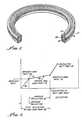
- FIG 2there is shown a load-deflection curve, A, for the purpose of illustrating the characteristics of radially resilient canted coiled springs.
- the load-deflection curvemay be constant or show a slight increase, as shown in Figure 2.
- the area between the minimum load point 22 and the maximum load point 24is known as the working deflection range 26.
- the springis normally loaded for operation within this range, as indicated by point 28, for a typical spring utilized in conjunction with seal, gasket, or the like, for sealing purposes.
- the load-deflection characteristicsmay be determined with a test jig 30 as shown in Figure 3.
- a radially resilient spring 32is held within a housing 34 by a fixture 36, thereby entrapping the spring 32 in a cavity 38.
- a circumferential spacer 40is used to load the outside diameter of the spring 32 and the force required to pass a plug 42 through the inside diameter of the spring 32 is measured.
- Figure 4shows in schematic form, a cross-section of a canted coil spring 12, in accordance with the present invention, with a turn angle of ⁇ , a measured coil width of C.W, a measured coil height of CH and a measured spring height H of the spring 12.
- the turn anglemay be clockwise (bold lines) or counterclockwise. (Dashed lines).
- the turn angle ⁇may be defined as an angle formed by a generally circular spring forming a cone or inverted cone, depending on the position of the spin, and measuring the turn angle for the horizontal to the intersection through the center line 46 of the spring 12.
- a radially resilient springmay be turned up counterclockwise, for example, 30 degrees, as shown in Figure 5b, or turned clockwise, as for example, shown in Figures 5d and 5e, with 30 degrees and 60 degrees turn angles, respectively. It should be appreciated that while the springs shown are shown with a circular shape, other shapes are possible, such as elliptical or rectangular, depending upon the configuration of the mating parts between which the spring 12 and/or seal 16 are to be placed.
- the turn angle -is defined as an angle formed by a generally circular spring forming a cone or an inverted cone, depending on the position of the spring and measuring the angle ⁇ from the horizontal to the intersection through the centerline of each cone, or inverted cone.
- the turn angle ⁇By varying the turn angle ⁇ , different loads can be obtained and the degree of loading depends upon the turn angle ⁇ . That is, the higher the turn angle ⁇ , the higher the force developed, as will be hereinafter demonstrated.
- the force developed upon loadingis independent upon whether the spring is in the cone shape as shown in Figure 5b, or an inverted cone as shown in 5d. That is, the springs in 5b and 5d will perform in identical fashion.
- Figures 6a and 6bshow a spring 12 having a trailing portion 50 defined by a back angle 52 made between the trailing portion 50 and a normal 54 to centerline 56 of the spring.
- a front angle 60defines a leading portion 62 of the spring 12 by the angle the leading portion 62 makes with a normal 64 to the centerline 56.
- Figure 6ashows the spring 12 having the trailing portion 50 along the inside diameter of the spring, with Figure 6b showing a spring 12a having the trailing portion 50 along the outside diameter of the spring.
- each revolutionincludes a trailing portion and a leading portion, with the leading portion advancing movement along the centerline more than the advancement along the centerline when following the trailing portion of the coil.
- inside back angle canted coil springs and outside angle canted coil springsmay be had from the hereinabove referenced copending patent applications which are herewith expressively incorporated by reference thereto.
- the effect of the trailing portion being disposed on the inside or the outside of the canted coil spring 12is an important parameter in the tayloring of radially resilient springs to have specific load-deflection characteristics.
- the loadwhen loading the spring 12 radially, the load is greater when the turn angle is 90 degrees than when the turn angle is 0 degrees and such load increases progressively from 0 degrees to 90 degrees.
- a spring 12 with the back angle 52, or trailing portion 50 along the inside as I.D. of the springwill develop substantially higher force than a spring 12a having a back angle 52 or trailing portion 50 along the outside as O.D. of the spring with both springs having the same turn angle.
- this discoveryenables greater tayloring ability. That is, a greater range of wire size and coil spacing can be used while still exerting the same or greater force in response to deflection. This has significant advantage when the spring is used in conjunction with a seal as hereinbefore described.
- Table 1sets forth the parameters of springs made in accordance with the present invention including the turn angle, number of coils, inside diameter (I.D.), the measured angle, coil spacing, wire diameter (W.D.), coil height (h) and coil diameter (d) to wire diameter. Most of these parameters are illustrated in Figures 6 and 6B.
- the springsare grouped in three categories; and RF 106MB, which has coil spacing of 0.018 inch, RF 106, MB(CC) having coil spacing of 0.0138 inch and RF X11661 having coil spacing of 0.033 inch. It should be pointed out that the greater the spacing between the coils, the greater difference between springs with a 0 degree turn angle and the spring with a 90 degree turn angle. This is generally shown in Figures 7-12 hereinafter described in greater detail.
- Figures 9 and 10each show four curves corresponding to spring RF 106MB(CC) having a spring spacing of 0.018 inches back angle of about 17 degrees and a front angle of about 31.5 degrees.
- Figure 9is a plot of those springs in which the back angle was measured at 17 degrees and Figure 10 represents springs in which the front angle was measured at 31.5 degrees. All of the curves show a general increase in the force-deflection curve in the working deflection range as the turn angle is increased from 0 to 90 degrees. In this instance, the variation between the 0 turn angle spring and the 90 degree angle spring was 31 percent, for the back angle measured spring and 33 percent for the front angle spring.
- Figures 11 and 12show the results of force-deflection testing for spring RF X11661 using turn angles from 0 to 90 degrees, as set forth in Table 1, Figure 11 showing spring in which the back angle was measured and Figure 12 showing the spring in which the front angle was measured. In each instance, the nominal back angle is 16 degrees and nominal front angle as 38 degrees.
- a spring with a turn angle of 90 degreeshas a 77 percent force higher than the spring with a 0 degree turn angle.
- Figure 12shows the difference between the 90 degree turn angle and the 0 degree turn angle of only 37 percent.
- the wiremay be fabricated counterclockwise or clockwise and, accordingly, the coils may counterclockwise or clockwise. In either case, the performance is the same as long as the back angle and front angles are the same.
Landscapes
- Engineering & Computer Science (AREA)
- General Engineering & Computer Science (AREA)
- Mechanical Engineering (AREA)
- Springs (AREA)
- Gasket Seals (AREA)
- Sealing Devices (AREA)
- Sealing With Elastic Sealing Lips (AREA)
Abstract
Description
- The present invention generally relates to canted-coiled springs and seals and, more particularly, relates to radially resilient canted-coiled springs having a preselected turn angle for enabling specific radial load-deflection characteristics.
- The load deflection characteristics of garter-type axial springs have been studied extensively, see companion copending European Patent Application No.89 107 379.3,filed April 24, 1989, which is to be incorporated, by specific reference thereto, into the present application. As is explained in the reference, many parameters, including the wire size, the coil height, the coil spacing, and the front angle, which defines a leading portion of each canted spring coil may be varied to tailor the load-deflection characteristics of the spring.
- As set forth in companion European Patent Applications No. 89 107 381.9 and 89 107 382.7, each filed on April 24, 1989, and incorporated herewith by specific reference thereto, springs may also have coils which are interconnected in a manner forming a garter-type axially resilient coil spring with the trailing portion along an outside diameter of the garter-type axially resilient coil spring, and the leading portion along an inside diameter of the garter-type axially resilient coil spring, or with the trailing portion along an inside diameter of the garter-type axially resilient coil spring and the leading portion along an outside diameter of the garter-type axially resilient coil spring. These references teach the tailoring of the load-deflection characteristics of a garter-type axially resilient coil spring beyond the range normally achieved with conventional garter-type axially resilient coil springs.
- This feature enables a spring to be formulated with generally higher load-deflection characteristics. That is, the spring is able to exert a greater force in response to a given deflection than a conventional spring having the same dimensions and wire size.
- As a result, these springs can be fabricated from smaller wire and have a closer coil spacing, while still exerting the same force in response to deflection as prior art springs.
- It should be recognized that this characteristic is quite important, particularly when the springs are used in conjunction with a seal. Because seals are generally made from a soft material to enhance their sealing characteristics, they must be evenly loaded. That is, the stress concentration on the seal should be uniform in order that relatively high and low pressure points do not occur across the face of the seal, which leads to inefficient sealing. When non uniform loading occurs, the resultant high pressure points are subject to greater force and consequently greater wear, while at the same time, the necessary sealing force may not be provided in the low pressure points, the latter leading to providing unnecessarily high force concentration to the spring in order to effect proper sealing.
- The present invention concerns a radially resilient canted coiled spring having a turn angle, as hereinafter defined and discussed, which can be varied in order to achieve higher load-deflection characteristics than heretofore possible utilizing the same wire diameters. The advantages of higher loading have been hereinabove discussed. In addition, the specific relationship and working resilient range of springs made in accordance with the present invention, can also be used to advantage and provide springs with tailored load-deflection characteristics which were not heretofore possible.
- In accordance with the present invention, a radially resilient canted coiled spring seal includes a plurality of coils canted along a centerline thereof, with back angle means for defining the disposition of a trailing portion of each coil with respect to a line normal to the centerline.
- It should be appreciated that the determination of the force-deflection characteristics apply only to springs which are allowed to flex in an uninhibited manner as distinguished from "springs" which are filled with an elastomer, or the like, as set forth in U.S. Patent No. 3,183,010 to Bram, the latter truly being characterized as reinforcement elements rather than springs.
- In accordance with the present invention, the back angle means determines, in combination with the turn angle, hereinafter described, the load-deflection characteristics of the spring which includes the peak point and the working deflection range of the spring. As set forth in the hereinabove referenced companion patent application entitled, "Outside Back Angle Canted Coil Spring", by controlling the back angle, which defines the trailing portion of each coil, the resilient characteristics can be designed to meet criteria heretofore not possible without the control, selection and an adjustment of the back angle.
- Means orienting said plurality of coils at turn angle are provided for further defining the load-deflection characteristics of the radially resilient canted coiled spring, said turn angle being greater than zero and less than 90 degrees.
- Specifically, means orienting the plurality of coils may include annular seal means, with the latter providing means defining a cavity for supporting and orienting the radially resilient canted coiled spring with a turn angle of greater than zero degrees and less than 90 degrees. In addition, the radially resilient canted coiled spring may have the trailing portion disposed along an outside diameter thereof and the leading portion disposed along an inside diameter thereof. The back angle may be about 4 degrees and the front angle may be less than about 55 degrees.
- Thereafter, two ends of the wound wire are attached in a manner forming a radially resilient canted coiled spring in an orientation defined by a turn angle, with the turn angle being greater than zero degrees and less than 90 degrees.
- In the winding of a spring, the resulting, or measured, front and back angles may vary from the preselected values thereof. It has been found that springs made with the same preselected front and back angle values but sorted thereafter according to the measured value of the front angle or back angle have different load-deflection characteristics.
- It has been unexpectedly found that a radially resilient canted coiled spring measured by the back angle has a higher load-deflection characteristic than a radially resilient canted coiled spring measured by the front angle despite the fact that the back angle and front angle have the same nominal valves for both springs.
- The advantages and features of the present invention will appear from the following description, when considered in conjunction with the accompanying drawings in which:
- Figure 1 is a perspective view of a radially loaded coiled spring seal, in accordance with the present invention, generally showing a plurality of coils interconnected in a manner forming a radially resilient canted coiled spring, with the spring being disposed in an annular seal with a preselected turn angle orientation for controlling the load-deflection characteristics of the radially resilient canted coiled spring, non-invasive support of the spring within the annular seal enabling independent working of the spring therein, thereby providing preselected force concentration on the sealing portions of the seal;
- Figure 2 shows a typical load-deflection curve for a spring for the purpose of defining the nomenclature thereof;
- Figure 3 shows test jig apparatus for the determination of the load-deflection characteristics as shown in Figure 2;
- Figure 4 is a schematic of a radially loaded coiled spring with turn angle ϑ shown for the purpose of illustrating how the turn angle ϑ may be determined;
- Figures 5a, b, c and d and e illustrate radially resilient canted coiled springs having various turn angles;
- Figures 6a, b are side views of springs showing leading and trailing portions of coils defined by front and back angles, respectively; and
- Figures 7-12 are load-deflection curves for various springs as herein described.
- Turning now to Figure 1, there is shown a radially resilient coiled spring and
seal 10, in accordance with the present invention, generally showing a radiallyresilient spring 12 with a plurality ofcoils 14 in anannular seal 16 which provides means for non-invasively supporting the garter-type axiallyresilient coil spring 12, in a preselected orientation for controlling the resilient characteristics thereof, as hereinafter described in greater detail. - In figure 2, there is shown a load-deflection curve, A, for the purpose of illustrating the characteristics of radially resilient canted coiled springs.
- As shown by curve A when a load is radially applied to a radially resilient spring, the spring exhibits general linear load-deflection relationship as shown by the
line segment 20 until it reachesminimum load point 22, which represents the point at which, after initial deflection, the load begins to remain relatively constant. - Between the
minimum load point 22 and a maximum load point 24, the load-deflection curve may be constant or show a slight increase, as shown in Figure 2. The area between theminimum load point 22 and the maximum load point 24 is known as the workingdeflection range 26. The spring is normally loaded for operation within this range, as indicated bypoint 28, for a typical spring utilized in conjunction with seal, gasket, or the like, for sealing purposes. - Loading of the spring beyond the maximum load point 24 results in abrupt deflection response until it reaches a butt point 30, which results in a permanent set in the spring as a result of overloading. Also indicated in Figure 2, is the
total deflection range 32 which is defined as the deflection between the unloaded spring and the deflection at the maximum load point 24. - The load-deflection characteristics may be determined with a test jig 30 as shown in Figure 3. A radially
resilient spring 32 is held within ahousing 34 by afixture 36, thereby entrapping thespring 32 in a cavity 38. Acircumferential spacer 40 is used to load the outside diameter of thespring 32 and the force required to pass aplug 42 through the inside diameter of thespring 32 is measured. - Figure 4 shows in schematic form, a cross-section of a
canted coil spring 12, in accordance with the present invention, with a turn angle of ϑ, a measured coil width of C.W, a measured coil height of CH and a measured spring height H of thespring 12. As shown in Figures 4, the turn angle may be clockwise (bold lines) or counterclockwise. (Dashed lines). The turn angle ϑ may be defined as an angle formed by a generally circular spring forming a cone or inverted cone, depending on the position of the spin, and measuring the turn angle for the horizontal to the intersection through thecenter line 46 of thespring 12. - As shown in Figures 5a, b, c, d and e, a radially resilient spring may be turned up counterclockwise, for example, 30 degrees, as shown in Figure 5b, or turned clockwise, as for example, shown in Figures 5d and 5e, with 30 degrees and 60 degrees turn angles, respectively. It should be appreciated that while the springs shown are shown with a circular shape, other shapes are possible, such as elliptical or rectangular, depending upon the configuration of the mating parts between which the
spring 12 and/orseal 16 are to be placed. - As shown in the Figures, the turn angle - is defined as an angle formed by a generally circular spring forming a cone or an inverted cone, depending on the position of the spring and measuring the angle ϑ from the horizontal to the intersection through the centerline of each cone, or inverted cone. By varying the turn angle ϑ, different loads can be obtained and the degree of loading depends upon the turn angle ϑ. That is, the higher the turn angle ϑ, the higher the force developed, as will be hereinafter demonstrated. It should be noted that the force developed upon loading, is independent upon whether the spring is in the cone shape as shown in Figure 5b, or an inverted cone as shown in 5d. That is, the springs in 5b and 5d will perform in identical fashion.
- Turning to Figure 6a and 6b, there is shown yet another variation of springs made in accordance with the present invention.
- Figures 6a and 6b show a
spring 12 having atrailing portion 50 defined by aback angle 52 made between thetrailing portion 50 and a normal 54 to centerline 56 of the spring. Afront angle 60 defines a leadingportion 62 of thespring 12 by the angle the leadingportion 62 makes with a normal 64 to the centerline 56. Figure 6a shows thespring 12 having thetrailing portion 50 along the inside diameter of the spring, with Figure 6b showing a spring 12a having thetrailing portion 50 along the outside diameter of the spring. As can be seen, from Figures 6a and b, as each coil is traced in a circular-like manner about the centerline, each revolution includes a trailing portion and a leading portion, with the leading portion advancing movement along the centerline more than the advancement along the centerline when following the trailing portion of the coil. - A more detailed description of inside back angle canted coil springs and outside angle canted coil springs may be had from the hereinabove referenced copending patent applications which are herewith expressively incorporated by reference thereto. The effect of the trailing portion being disposed on the inside or the outside of the canted
coil spring 12 is an important parameter in the tayloring of radially resilient springs to have specific load-deflection characteristics. - As hereinafter shown, when loading the
spring 12 radially, the load is greater when the turn angle is 90 degrees than when the turn angle is 0 degrees and such load increases progressively from 0 degrees to 90 degrees. In addition, aspring 12 with theback angle 52, or trailingportion 50 along the inside as I.D. of the spring will develop substantially higher force than a spring 12a having aback angle 52 or trailingportion 50 along the outside as O.D. of the spring with both springs having the same turn angle. - As hereinabove pointed out, this discovery enables greater tayloring ability. That is, a greater range of wire size and coil spacing can be used while still exerting the same or greater force in response to deflection. This has significant advantage when the spring is used in conjunction with a seal as hereinbefore described.
- Table 1 sets forth the parameters of springs made in accordance with the present invention including the turn angle, number of coils, inside diameter (I.D.), the measured angle, coil spacing, wire diameter (W.D.), coil height (h) and coil diameter (d) to wire diameter. Most of these parameters are illustrated in Figures 6 and 6B. The springs are grouped in three categories; and RF 106MB, which has coil spacing of 0.018 inch, RF 106, MB(CC) having coil spacing of 0.0138 inch and RF X11661 having coil spacing of 0.033 inch. It should be pointed out that the greater the spacing between the coils, the greater difference between springs with a 0 degree turn angle and the spring with a 90 degree turn angle. This is generally shown in Figures 7-12 hereinafter described in greater detail.
- Turning now to Figure 7, there is shown the force or deflection curves for springs RF 106MB having turn angles (TA) of 0, 30, 60 and 90 degrees. It can be observed that in the working deflection range (see Figure 2 for a definition) the force increases as the turn angle increases and the difference in load between the 0 degree turn angle and the 90 degree turn angle is about 39 percent.
- As a comparison, shown in Figure 8, as the load force-deflection characteristics of spring RF 106MB for turn angles of 0, 30, 60 and 90 in which the measured front angle is 30 degrees while

- Similarly, Figures 9 and 10 each show four curves corresponding to spring RF 106MB(CC) having a spring spacing of 0.018 inches back angle of about 17 degrees and a front angle of about 31.5 degrees. Figure 9 is a plot of those springs in which the back angle was measured at 17 degrees and Figure 10 represents springs in which the front angle was measured at 31.5 degrees. All of the curves show a general increase in the force-deflection curve in the working deflection range as the turn angle is increased from 0 to 90 degrees. In this instance, the variation between the 0 turn angle spring and the 90 degree angle spring was 31 percent, for the back angle measured spring and 33 percent for the front angle spring.
- Figures 11 and 12 show the results of force-deflection testing for spring RF X11661 using turn angles from 0 to 90 degrees, as set forth in Table 1, Figure 11 showing spring in which the back angle was measured and Figure 12 showing the spring in which the front angle was measured. In each instance, the nominal back angle is 16 degrees and nominal front angle as 38 degrees.
- As shown in Figure 11, a spring with a turn angle of 90 degrees has a 77 percent force higher than the spring with a 0 degree turn angle. Figure 12 shows the difference between the 90 degree turn angle and the 0 degree turn angle of only 37 percent.
- It should be appreciated that the wire may be fabricated counterclockwise or clockwise and, accordingly, the coils may counterclockwise or clockwise. In either case, the performance is the same as long as the back angle and front angles are the same.
- Although there has been described hereinabove a specific radially resistant canted coil spring and manufacture of an invention in accordance with the present invention, for purposes of illustrating the manner in which the invention may be used to advantage, it should be appreciated that the invention is not limited thereto. Accordingly, any and all modifications, variations, or equivalent arrangements which may occur to those skilled in the art, should be considered to be within the scope of the invention as defined in the appended claims.

Claims (10)
- a plurality of coil means (14), interconnected and canted along a centerline (56) thereof, for causing the coiled spring (12) to exert a generally constant force over a preselected range of deflection of the coiled spring (12) in response to radial loading;
- back angle means for defining the disposition of a trailing portion (50) of each coil (14) with respect to a line (54) normal to the centerline (56);
- front angle means for defining the disposition of a leading portion (62) of each coil (14) with respect to the normal line (54), said front angle means being greater than said back angle means; and
- means, orienting said plurality of coil means (14) at a turn angle Θ, for controlling the magnitude of the generally constant force within the preselected range of deflection, said turn angle Θ being greater than zero degrees and less than 90 degrees.
- a plurality of coils (14) canted along a centerline (56) thereof;
- back angle means for defining the disposition of a trailing portion (56) of each coil (14) with respect to a line (54) normal to the centerline (56);
- front angle means for defining the disposition of a leading portion (62) of each coil (14) with respect to the normal line (54), said front angle means being greater than said back angle means;
- said coils (14) being interconnected in a manner forming a radially resilient canted coiled spring (12); and
- annular seal means (16) for non-invasively supporting the radially resilient canted coiled spring (12) in an orientation for controlling the resilient characteristics of the radially resilient canted coiled spring (12).
Applications Claiming Priority (2)
| Application Number | Priority Date | Filing Date | Title |
|---|---|---|---|
| US232430 | 1988-08-15 | ||
| US07/232,430US4893795A (en) | 1988-08-15 | 1988-08-15 | Radially loaded canted coiled spring with turn angle |
Publications (2)
| Publication Number | Publication Date |
|---|---|
| EP0355611A1true EP0355611A1 (en) | 1990-02-28 |
| EP0355611B1 EP0355611B1 (en) | 1994-12-21 |
Family
ID=22873073
Family Applications (1)
| Application Number | Title | Priority Date | Filing Date |
|---|---|---|---|
| EP89114867AExpired - LifetimeEP0355611B1 (en) | 1988-08-15 | 1989-08-11 | Radially resilient, canted-coil spring with turn angle and seal |
Country Status (4)
| Country | Link |
|---|---|
| US (1) | US4893795A (en) |
| EP (1) | EP0355611B1 (en) |
| AT (1) | ATE116042T1 (en) |
| DE (1) | DE68920090T2 (en) |
Cited By (3)
| Publication number | Priority date | Publication date | Assignee | Title |
|---|---|---|---|---|
| EP0437227A3 (en)* | 1990-01-08 | 1991-10-09 | Peter J. Balsells | Canted coil spring assembly and method |
| EP0491258A1 (en)* | 1990-12-17 | 1992-06-24 | Peter J. Balsells | Spring-loaded ring seal assembly |
| US5161806A (en)* | 1990-12-17 | 1992-11-10 | Peter J. Balsells | Spring-loaded, hollow, elliptical ring seal |
Families Citing this family (55)
| Publication number | Priority date | Publication date | Assignee | Title |
|---|---|---|---|---|
| US5108078A (en)* | 1988-04-25 | 1992-04-28 | Peter J. Balsells | Canted-coil spring loaded while in a cavity |
| US5160122A (en)* | 1990-03-20 | 1992-11-03 | Peter J. Balsells | Coil spring with an elastomer having a hollow coil cross section |
| US5139276A (en)* | 1988-04-25 | 1992-08-18 | Peter J. Balsells | Canted coil spring radially loaded while in a cavity |
| US5139243A (en)* | 1990-07-30 | 1992-08-18 | Peter J. Balsells | Axial canted coil springs in sinusoidal form |
| US5474309A (en)* | 1993-06-11 | 1995-12-12 | Bal Seal Engineering Company, Inc. | Gasket assembly for sealing electromagnetic waves |
| US5411348A (en)* | 1993-10-26 | 1995-05-02 | Bal Seal Engineering Company, Inc. | Spring mechanism to connect, lock and unlock, members |
| US5545842A (en)* | 1993-10-26 | 1996-08-13 | Bal Seal Engineering Company, Inc. | Radially mounted spring to connect, lock and unlock, and for snap-on fastening, and for mechanical, electromagnetic shielding, electrical conductivity, and thermal dissipation with environmental sealing |
| US5607006A (en)* | 1994-11-14 | 1997-03-04 | Doehler-Jarvis Technologies, Inc. | Casting method and apparatus for use therein |
| JPH1172130A (en) | 1997-07-07 | 1999-03-16 | Bal Seal Eng Co Inc | Spring for diametric direction provided with coil tilted along major axis and spring for axial line direction |
| US6091175A (en)* | 1998-03-12 | 2000-07-18 | Camco International, Inc. | Self-centering rotor bearing assembly for submersible pump motors |
| US6416330B1 (en) | 2000-07-17 | 2002-07-09 | Cray Inc. | Canted coil spring conductor electrical circuit connector |
| WO2003046392A2 (en)* | 2001-11-21 | 2003-06-05 | Bal Seal Engineering Co., Inc. | Connector with radial spring |
| AU2003217558A1 (en) | 2002-02-15 | 2003-09-09 | Bal Seal Engineering Co., Inc. | Medically implantable electrical connector with constant conductivity |
| AU2003279006A1 (en)* | 2002-09-30 | 2004-04-23 | Bal Seal Engineering Co., Inc. | Canted coil springs various designs |
| US7731947B2 (en) | 2003-11-17 | 2010-06-08 | Intarcia Therapeutics, Inc. | Composition and dosage form comprising an interferon particle formulation and suspending vehicle |
| JP2006518090A (en)* | 2003-02-18 | 2006-08-03 | バル・シール・エンジニアリング・カンパニー・インコーポレーテッド | Spring retaining connector |
| US8167285B2 (en) | 2003-06-04 | 2012-05-01 | Bal Seal Engineering Co., Inc. | Spring latching connectors radially and axially mounted |
| US9267526B2 (en) | 2003-06-04 | 2016-02-23 | Bal Seal Engineering, Inc. | Spring latching connectors |
| US7274964B2 (en)* | 2004-04-16 | 2007-09-25 | Bal Seal Engineering Co., Inc. | Use of an axial canted coil spring as an electrical contact to minimize resistivity variations under dynamic loads |
| US20050242910A1 (en)* | 2004-04-29 | 2005-11-03 | Balsells Peter J | Contact assembly |
| US11246913B2 (en) | 2005-02-03 | 2022-02-15 | Intarcia Therapeutics, Inc. | Suspension formulation comprising an insulinotropic peptide |
| WO2006083761A2 (en) | 2005-02-03 | 2006-08-10 | Alza Corporation | Solvent/polymer solutions as suspension vehicles |
| MX2008014870A (en) | 2006-05-30 | 2009-02-12 | Intarcia Therapeutics Inc | Two-piece, internal-channel osmotic delivery system flow modulator. |
| EP3421031A1 (en) | 2006-08-09 | 2019-01-02 | Intarcia Therapeutics, Inc | Osmotic delivery systems and piston assemblies |
| WO2008022014A2 (en)* | 2006-08-10 | 2008-02-21 | Research Sciences, Llc | Multimember extended range compressible seal |
| MX2009011123A (en) | 2007-04-23 | 2009-11-02 | Intarcia Therapeutics Inc | Suspension formulations of insulinotropic peptides and uses thereof. |
| US8114024B2 (en)* | 2007-08-20 | 2012-02-14 | Interson Corporation | Seal for a rotating shaft |
| WO2009076310A2 (en) | 2007-12-06 | 2009-06-18 | Bal Seal Engineering | In-line connector |
| US8328202B2 (en) | 2007-12-07 | 2012-12-11 | Bal Seal Engineering, Inc. | Seal assembly for high pressure dynamic and static services |
| WO2009102467A2 (en) | 2008-02-13 | 2009-08-20 | Intarcia Therapeutics, Inc. | Devices, formulations, and methods for delivery of multiple beneficial agents |
| US10247307B2 (en) | 2009-03-23 | 2019-04-02 | Bal Seal Engineering, Inc. | Interlocking composite seals |
| US8684362B2 (en) | 2009-08-12 | 2014-04-01 | Bal Seal Engineering, Inc. | Cartridge seal assemblies and associated methods |
| NZ598686A (en) | 2009-09-28 | 2014-05-30 | Intarcia Therapeutics Inc | Rapid establishment and/or termination of substantial steady-state drug delivery |
| US9010740B2 (en) | 2010-10-21 | 2015-04-21 | Veloce Labs, LLC | Multi-canted coils, tubes, and structures |
| US20120208755A1 (en) | 2011-02-16 | 2012-08-16 | Intarcia Therapeutics, Inc. | Compositions, Devices and Methods of Use Thereof for the Treatment of Cancers |
| US8428724B2 (en) | 2011-03-11 | 2013-04-23 | Greatbatch Ltd. | Low insertion force electrical connector for implantable medical devices |
| US9284970B2 (en) | 2012-09-14 | 2016-03-15 | Bal Seal Engineering, Inc. | Connector housings, use of, and method therefor |
| US9518626B2 (en) | 2012-11-13 | 2016-12-13 | Bal Seal Engineering, Inc. | Canted coil springs and assemblies and related methods |
| WO2014142799A1 (en) | 2013-03-12 | 2014-09-18 | Case Western Reserve University | Asymmetrical-force connector system |
| EP2971842B1 (en) | 2013-03-14 | 2019-07-10 | Bal Seal Engineering, Inc. | Canted coil spring with longitudinal component within and related methods |
| US10598241B2 (en) | 2014-02-26 | 2020-03-24 | Bal Seal Engineering, Inc. | Multi deflection canted coil springs and related methods |
| WO2015148865A1 (en) | 2014-03-26 | 2015-10-01 | Nelson Products, Inc. | Latching connector with radial grooves |
| US10151368B2 (en) | 2014-05-02 | 2018-12-11 | Bal Seal Engineering, Inc. | Nested canted coil springs, applications thereof, and related methods |
| EP3195415B1 (en) | 2014-09-15 | 2023-12-27 | Bal Seal Engineering, LLC | Connector assembly and method of assembling the same |
| US9889085B1 (en) | 2014-09-30 | 2018-02-13 | Intarcia Therapeutics, Inc. | Therapeutic methods for the treatment of diabetes and related conditions for patients with high baseline HbA1c |
| AU2016270984B2 (en) | 2015-06-03 | 2021-02-25 | Intarcia Therapeutics, Inc. | Implant placement and removal systems |
| US10487899B2 (en) | 2016-02-17 | 2019-11-26 | Nelson Products, Inc. | Canted coil spring shock absorber |
| JP7077237B2 (en) | 2016-05-16 | 2022-05-30 | インターシア セラピューティクス,インコーポレイティド | Glucagon Receptor Selective Polypeptides and Their Usage |
| USD860451S1 (en) | 2016-06-02 | 2019-09-17 | Intarcia Therapeutics, Inc. | Implant removal tool |
| USD840030S1 (en) | 2016-06-02 | 2019-02-05 | Intarcia Therapeutics, Inc. | Implant placement guide |
| MX2019008006A (en) | 2017-01-03 | 2019-08-29 | Intarcia Therapeutics Inc | METHODS INCLUDING THE CONTINUOUS ADMINISTRATION OF A GLP-1 RECEPTOR AGONIST AND THE CO-ADMINISTRATION OF A DRUG. |
| US10900531B2 (en) | 2017-08-30 | 2021-01-26 | Bal Seal Engineering, Llc | Spring wire ends to faciliate welding |
| US11353079B2 (en) | 2017-10-05 | 2022-06-07 | Bal Seal Engineering, Llc | Spring assemblies, applications of spring assemblies, and related methods |
| USD933219S1 (en) | 2018-07-13 | 2021-10-12 | Intarcia Therapeutics, Inc. | Implant removal tool and assembly |
| US10995812B2 (en) | 2019-02-27 | 2021-05-04 | Nelson Products, Inc. | Canted coil spring shock absorber |
Citations (2)
| Publication number | Priority date | Publication date | Assignee | Title |
|---|---|---|---|---|
| US3183010A (en)* | 1961-02-23 | 1965-05-11 | Ct De Rech S De Pont A Mousson | Reinforcement for sealing element and sealing element incorporating said reinforcement |
| GB2169378A (en)* | 1985-01-07 | 1986-07-09 | Balsells Eng Co | Coiled spring and coiled spring seal |
Family Cites Families (11)
| Publication number | Priority date | Publication date | Assignee | Title |
|---|---|---|---|---|
| US1473446A (en)* | 1922-06-06 | 1923-11-06 | Walter R Scott | Means for expanding piston rings |
| US1867723A (en)* | 1928-10-20 | 1932-07-19 | Troy Laundry Machinery Co | Convoluted spring |
| AT150912B (en)* | 1935-12-07 | 1937-10-11 | Siemens Ag | Arrangement for the resilient connection of parts of electrical discharge vessels. |
| US2610846A (en)* | 1949-12-02 | 1952-09-16 | Hanna Engineering Works | Packing ring |
| US2859033A (en)* | 1956-06-27 | 1958-11-04 | Hughes Aircraft Co | Constant force applying mechanism |
| US3223785A (en)* | 1959-12-30 | 1965-12-14 | Bell Telephone Labor Inc | Electronic telephone switching system |
| US3061060A (en)* | 1960-03-29 | 1962-10-30 | Gen Motors Corp | One-way clutch |
| US3468527A (en)* | 1968-03-08 | 1969-09-23 | North American Rockwell | Coil spring |
| US4826144A (en)* | 1988-04-25 | 1989-05-02 | Peter J. Balsells | Inside back angle canted coil spring |
| ATE94955T1 (en)* | 1988-04-25 | 1993-10-15 | Peter J Balsells | SELF-CLOSED ANROCULAR COIL SPRING WITH EXTERNAL REVERSE ANGLE. |
| US4830344A (en)* | 1988-04-25 | 1989-05-16 | Peter J. Balsells | Canted-coil spring with turn angle and seal |
- 1988
- 1988-08-15USUS07/232,430patent/US4893795A/ennot_activeExpired - Lifetime
- 1989
- 1989-08-11EPEP89114867Apatent/EP0355611B1/ennot_activeExpired - Lifetime
- 1989-08-11DEDE68920090Tpatent/DE68920090T2/ennot_activeExpired - Lifetime
- 1989-08-11ATAT89114867Tpatent/ATE116042T1/ennot_activeIP Right Cessation
Patent Citations (2)
| Publication number | Priority date | Publication date | Assignee | Title |
|---|---|---|---|---|
| US3183010A (en)* | 1961-02-23 | 1965-05-11 | Ct De Rech S De Pont A Mousson | Reinforcement for sealing element and sealing element incorporating said reinforcement |
| GB2169378A (en)* | 1985-01-07 | 1986-07-09 | Balsells Eng Co | Coiled spring and coiled spring seal |
Cited By (3)
| Publication number | Priority date | Publication date | Assignee | Title |
|---|---|---|---|---|
| EP0437227A3 (en)* | 1990-01-08 | 1991-10-09 | Peter J. Balsells | Canted coil spring assembly and method |
| EP0491258A1 (en)* | 1990-12-17 | 1992-06-24 | Peter J. Balsells | Spring-loaded ring seal assembly |
| US5161806A (en)* | 1990-12-17 | 1992-11-10 | Peter J. Balsells | Spring-loaded, hollow, elliptical ring seal |
Also Published As
| Publication number | Publication date |
|---|---|
| ATE116042T1 (en) | 1995-01-15 |
| US4893795A (en) | 1990-01-16 |
| DE68920090D1 (en) | 1995-02-02 |
| DE68920090T2 (en) | 1995-05-04 |
| EP0355611B1 (en) | 1994-12-21 |
Similar Documents
| Publication | Publication Date | Title |
|---|---|---|
| US4893795A (en) | Radially loaded canted coiled spring with turn angle | |
| US4830344A (en) | Canted-coil spring with turn angle and seal | |
| US4974821A (en) | Canted-coil spring with major axis radial loading | |
| US4876781A (en) | Method of making a garter-type axially resilient coiled spring | |
| US4826144A (en) | Inside back angle canted coil spring | |
| US5139276A (en) | Canted coil spring radially loaded while in a cavity | |
| US4964204A (en) | Method for making a garter-type axially-resilient coil spring | |
| US5108078A (en) | Canted-coil spring loaded while in a cavity | |
| US4915366A (en) | Outside back angle canted coil spring | |
| EP0339544B1 (en) | Garter spring with canted back angle located on outside diameter | |
| US5160122A (en) | Coil spring with an elastomer having a hollow coil cross section | |
| EP0469489B1 (en) | Axially loadable canted coil springs | |
| EP0711933B1 (en) | Coil spring with ends adapted for coupling without welding | |
| US5161806A (en) | Spring-loaded, hollow, elliptical ring seal | |
| US4319758A (en) | Ring seal | |
| GB2169378A (en) | Coiled spring and coiled spring seal | |
| EP1282792B1 (en) | Improved ring seal | |
| US3892398A (en) | Compression spring | |
| US5542682A (en) | Slant coil spring and seal | |
| US4572693A (en) | Ball-and-socket joint | |
| EP0351549A1 (en) | Spring loaded guide ring | |
| GB2164102A (en) | Improvement relating to ring seals | |
| US5239737A (en) | Method for manufacturing a spring assembly | |
| US4466624A (en) | Sealing arrangement | |
| EP0437227A2 (en) | Canted coil spring assembly and method |
Legal Events
| Date | Code | Title | Description |
|---|---|---|---|
| PUAI | Public reference made under article 153(3) epc to a published international application that has entered the european phase | Free format text:ORIGINAL CODE: 0009012 | |
| AK | Designated contracting states | Kind code of ref document:A1 Designated state(s):AT BE CH DE ES FR GB GR IT LI LU NL SE | |
| 17P | Request for examination filed | Effective date:19900818 | |
| 17Q | First examination report despatched | Effective date:19920326 | |
| GRAA | (expected) grant | Free format text:ORIGINAL CODE: 0009210 | |
| AK | Designated contracting states | Kind code of ref document:B1 Designated state(s):AT BE CH DE ES FR GB GR IT LI LU NL SE | |
| PG25 | Lapsed in a contracting state [announced via postgrant information from national office to epo] | Ref country code:GR Free format text:LAPSE BECAUSE OF FAILURE TO SUBMIT A TRANSLATION OF THE DESCRIPTION OR TO PAY THE FEE WITHIN THE PRESCRIBED TIME-LIMIT Effective date:19941221 Ref country code:LI Effective date:19941221 Ref country code:NL Effective date:19941221 Ref country code:AT Effective date:19941221 Ref country code:BE Effective date:19941221 Ref country code:ES Free format text:THE PATENT HAS BEEN ANNULLED BY A DECISION OF A NATIONAL AUTHORITY Effective date:19941221 Ref country code:CH Effective date:19941221 Ref country code:IT Free format text:LAPSE BECAUSE OF FAILURE TO SUBMIT A TRANSLATION OF THE DESCRIPTION OR TO PAY THE FEE WITHIN THE PRE;WARNING: LAPSES OF ITALIAN PATENTS WITH EFFECTIVE DATE BEFORE 2007 MAY HAVE OCCURRED AT ANY TIME BEFORE 2007. THE CORRECT EFFECTIVE DATE MAY BE DIFFERENT FROM THE ONE RECORDED.SCRIBED TIME-LIMIT Effective date:19941221 | |
| REF | Corresponds to: | Ref document number:116042 Country of ref document:AT Date of ref document:19950115 Kind code of ref document:T | |
| ET | Fr: translation filed | ||
| REF | Corresponds to: | Ref document number:68920090 Country of ref document:DE Date of ref document:19950202 | |
| PG25 | Lapsed in a contracting state [announced via postgrant information from national office to epo] | Ref country code:SE Effective date:19950321 | |
| REG | Reference to a national code | Ref country code:CH Ref legal event code:PL | |
| NLV1 | Nl: lapsed or annulled due to failure to fulfill the requirements of art. 29p and 29m of the patents act | ||
| PG25 | Lapsed in a contracting state [announced via postgrant information from national office to epo] | Ref country code:LU Free format text:LAPSE BECAUSE OF NON-PAYMENT OF DUE FEES Effective date:19950831 | |
| PLBE | No opposition filed within time limit | Free format text:ORIGINAL CODE: 0009261 | |
| STAA | Information on the status of an ep patent application or granted ep patent | Free format text:STATUS: NO OPPOSITION FILED WITHIN TIME LIMIT | |
| 26N | No opposition filed | ||
| REG | Reference to a national code | Ref country code:GB Ref legal event code:IF02 | |
| PGFP | Annual fee paid to national office [announced via postgrant information from national office to epo] | Ref country code:FR Payment date:20080818 Year of fee payment:20 | |
| PGFP | Annual fee paid to national office [announced via postgrant information from national office to epo] | Ref country code:GB Payment date:20080827 Year of fee payment:20 | |
| PGFP | Annual fee paid to national office [announced via postgrant information from national office to epo] | Ref country code:DE Payment date:20080930 Year of fee payment:20 | |
| PG25 | Lapsed in a contracting state [announced via postgrant information from national office to epo] | Ref country code:GB Free format text:LAPSE BECAUSE OF EXPIRATION OF PROTECTION Effective date:20090810 |