EP0354851B1 - Technique of stereoscopic image display - Google Patents
Technique of stereoscopic image displayDownload PDFInfo
- Publication number
- EP0354851B1 EP0354851B1EP89402262AEP89402262AEP0354851B1EP 0354851 B1EP0354851 B1EP 0354851B1EP 89402262 AEP89402262 AEP 89402262AEP 89402262 AEP89402262 AEP 89402262AEP 0354851 B1EP0354851 B1EP 0354851B1
- Authority
- EP
- European Patent Office
- Prior art keywords
- pixels
- viewer
- lenticular lens
- left eye
- eye images
- Prior art date
- Legal status (The legal status is an assumption and is not a legal conclusion. Google has not performed a legal analysis and makes no representation as to the accuracy of the status listed.)
- Expired - Lifetime
Links
- 238000000034methodMethods0.000titleclaimsdescription20
- 230000003252repetitive effectEffects0.000claimsdescription4
- 239000011521glassSubstances0.000description10
- 210000003128headAnatomy0.000description10
- 238000003491arrayMethods0.000description4
- 238000010586diagramMethods0.000description4
- 239000004973liquid crystal related substanceSubstances0.000description4
- 238000001514detection methodMethods0.000description2
- 230000003287optical effectEffects0.000description2
- 235000010724Wisteria floribundaNutrition0.000description1
- 230000001771impaired effectEffects0.000description1
- 230000000007visual effectEffects0.000description1
Images


Classifications
- H—ELECTRICITY
- H04—ELECTRIC COMMUNICATION TECHNIQUE
- H04N—PICTORIAL COMMUNICATION, e.g. TELEVISION
- H04N13/00—Stereoscopic video systems; Multi-view video systems; Details thereof
- G—PHYSICS
- G02—OPTICS
- G02B—OPTICAL ELEMENTS, SYSTEMS OR APPARATUS
- G02B27/00—Optical systems or apparatus not provided for by any of the groups G02B1/00 - G02B26/00, G02B30/00
- G02B27/0093—Optical systems or apparatus not provided for by any of the groups G02B1/00 - G02B26/00, G02B30/00 with means for monitoring data relating to the user, e.g. head-tracking, eye-tracking
- G—PHYSICS
- G02—OPTICS
- G02B—OPTICAL ELEMENTS, SYSTEMS OR APPARATUS
- G02B30/00—Optical systems or apparatus for producing three-dimensional [3D] effects, e.g. stereoscopic images
- G02B30/20—Optical systems or apparatus for producing three-dimensional [3D] effects, e.g. stereoscopic images by providing first and second parallax images to an observer's left and right eyes
- G02B30/26—Optical systems or apparatus for producing three-dimensional [3D] effects, e.g. stereoscopic images by providing first and second parallax images to an observer's left and right eyes of the autostereoscopic type
- G02B30/27—Optical systems or apparatus for producing three-dimensional [3D] effects, e.g. stereoscopic images by providing first and second parallax images to an observer's left and right eyes of the autostereoscopic type involving lenticular arrays
- H—ELECTRICITY
- H04—ELECTRIC COMMUNICATION TECHNIQUE
- H04N—PICTORIAL COMMUNICATION, e.g. TELEVISION
- H04N13/00—Stereoscopic video systems; Multi-view video systems; Details thereof
- H04N13/30—Image reproducers
- H04N13/302—Image reproducers for viewing without the aid of special glasses, i.e. using autostereoscopic displays
- H04N13/305—Image reproducers for viewing without the aid of special glasses, i.e. using autostereoscopic displays using lenticular lenses, e.g. arrangements of cylindrical lenses
- H—ELECTRICITY
- H04—ELECTRIC COMMUNICATION TECHNIQUE
- H04N—PICTORIAL COMMUNICATION, e.g. TELEVISION
- H04N13/00—Stereoscopic video systems; Multi-view video systems; Details thereof
- H04N13/30—Image reproducers
- H04N13/366—Image reproducers using viewer tracking
- H04N13/376—Image reproducers using viewer tracking for tracking left-right translational head movements, i.e. lateral movements
- H—ELECTRICITY
- H04—ELECTRIC COMMUNICATION TECHNIQUE
- H04N—PICTORIAL COMMUNICATION, e.g. TELEVISION
- H04N13/00—Stereoscopic video systems; Multi-view video systems; Details thereof
- H04N13/30—Image reproducers
- H04N13/398—Synchronisation thereof; Control thereof
- G—PHYSICS
- G02—OPTICS
- G02B—OPTICAL ELEMENTS, SYSTEMS OR APPARATUS
- G02B3/00—Simple or compound lenses
- G02B3/0006—Arrays
- G02B3/0037—Arrays characterized by the distribution or form of lenses
- G02B3/005—Arrays characterized by the distribution or form of lenses arranged along a single direction only, e.g. lenticular sheets
- H—ELECTRICITY
- H04—ELECTRIC COMMUNICATION TECHNIQUE
- H04N—PICTORIAL COMMUNICATION, e.g. TELEVISION
- H04N13/00—Stereoscopic video systems; Multi-view video systems; Details thereof
- H04N13/30—Image reproducers
- H04N13/302—Image reproducers for viewing without the aid of special glasses, i.e. using autostereoscopic displays
- H04N13/32—Image reproducers for viewing without the aid of special glasses, i.e. using autostereoscopic displays using arrays of controllable light sources; using moving apertures or moving light sources
- H—ELECTRICITY
- H04—ELECTRIC COMMUNICATION TECHNIQUE
- H04N—PICTORIAL COMMUNICATION, e.g. TELEVISION
- H04N13/00—Stereoscopic video systems; Multi-view video systems; Details thereof
- H04N13/30—Image reproducers
- H04N13/332—Displays for viewing with the aid of special glasses or head-mounted displays [HMD]
- H04N13/334—Displays for viewing with the aid of special glasses or head-mounted displays [HMD] using spectral multiplexing
- H—ELECTRICITY
- H04—ELECTRIC COMMUNICATION TECHNIQUE
- H04N—PICTORIAL COMMUNICATION, e.g. TELEVISION
- H04N13/00—Stereoscopic video systems; Multi-view video systems; Details thereof
- H04N13/30—Image reproducers
- H04N13/332—Displays for viewing with the aid of special glasses or head-mounted displays [HMD]
- H04N13/337—Displays for viewing with the aid of special glasses or head-mounted displays [HMD] using polarisation multiplexing
- H—ELECTRICITY
- H04—ELECTRIC COMMUNICATION TECHNIQUE
- H04N—PICTORIAL COMMUNICATION, e.g. TELEVISION
- H04N13/00—Stereoscopic video systems; Multi-view video systems; Details thereof
- H04N13/30—Image reproducers
- H04N13/332—Displays for viewing with the aid of special glasses or head-mounted displays [HMD]
- H04N13/341—Displays for viewing with the aid of special glasses or head-mounted displays [HMD] using temporal multiplexing
- H—ELECTRICITY
- H04—ELECTRIC COMMUNICATION TECHNIQUE
- H04N—PICTORIAL COMMUNICATION, e.g. TELEVISION
- H04N13/00—Stereoscopic video systems; Multi-view video systems; Details thereof
- H04N13/30—Image reproducers
- H04N13/349—Multi-view displays for displaying three or more geometrical viewpoints without viewer tracking
- H—ELECTRICITY
- H04—ELECTRIC COMMUNICATION TECHNIQUE
- H04N—PICTORIAL COMMUNICATION, e.g. TELEVISION
- H04N13/00—Stereoscopic video systems; Multi-view video systems; Details thereof
- H04N13/30—Image reproducers
- H04N13/363—Image reproducers using image projection screens
Definitions
- the present inventionrelates to a technique of stereoscopic image display applicable to stereoscopic television sets, stereoscopic video recorders/players, stereoscopic videotelephones for performing communications at remote locations, and the like.
- Techniques of displaying a stereoscopic imageinclude a glass scheme using specific glasses, and a lenticular scheme using a lenticular lens sheet.
- a scheme of displaying a stereoscopic image using polarized glasses, liquid-crystal shutter glasses, or an anaglyph schemeis known.
- a viewer of a stereoscopic imagefeels unnatural and uneasy since he or she must wear glasses.
- images wearing glassesare displayed, naturalness is considerably impaired.
- a technique of displaying a stereoscopic image by the lenticular schemeincludes a direct viewing type wherein a lenticular lens sheet is arranged on the surface of a display such as a CRT, a liquid-crystal display, or the like, and a projection type for projecting an image on a lenticular lens sheet using a projector.
- a viewercan watch a stereoscopic image without wearing glasses.
- a large number of images projected from 6 to 8 placesare required, and the arrangement of an apparatus becomes complicated and the apparatus becomes expensive.
- a technique for realizing such a lenticular scheme by images projected from two placesa technique for mechanically tracking a head portion is known (e.g., Alfred Schwartz; "Head Tracking Display” IEEE Trans. ED-33, 8 (Aug, 1986)).
- a tracking speedcannot be increased due to mechanical tracking.
- the binocular position of a vieweris detected by a detection means so that the pixel for the left eye image is always incident on the left eye and the pixel for the right eye image is always incident on the right eye, and the positions of the pixels for the right and left eye images on the combined image are changed on the basis of the detection signal according to the binocular position of the viewer.
- right and left eye images displayed by a display devicesuch as a liquid-crystal display are controlled by detecting the binocular position of the viewer.
- a right or left eye image signalwhich is input to a corresponding one of two (or a plurality of sets of) projectors is controlled by detecting the binocular position of the viewer.
- the pitch of each lenticular lensis set to be slightly smaller than the repetitive pitch of a pair of pixels for right and left eye images on the combined image, so that the centers of all the pairs of pixels for the right and left eye images are projected to the center of the two eyes.
- each pixel of a pair of pixels for right and left eye images corresponding to one pitch of the lenticular lensis constituted by a plurality of micropixels, and the positions of pixels for the right and left eye images on the combined image are changed in units of micropixels, thus expanding an area capable of stereoscopic viewing.
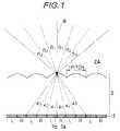
- Figs. 1 to 4are views for explaining the principle of the present invention.
- Fig. 1shows a state near a display screen (direct viewing type) or a diffusive layer (projection type).
- reference numeral 1denotes a combined image obtained by combining pixels for a left eye image (to be referred to as L pixels hereinafter) and pixels for a right eye image (to be referred to as R pixels hereinafter).
- L pixelsleft eye image
- R pixelspixels for a right eye image
- Each pair of R and L pixelscorrespond to each of lenticular lenses 2A constituting a lenticular lens sheet 2.
- the combined image 1is formed on a focal plane of the lenticular lenses 2A. A light beam passing through the central lenticular lens 2A will be explained below.
- n ⁇ sin( ⁇ 1)sin( ⁇ 1) where ⁇ 1 is the emerging angle, and n is the refractive index of the lenticular lens 2A.
- Fig. 2shows the above-mentioned state as well as the viewer.
- a viewer 5when a viewer 5 is located at the central position indicated by a solid line, since light beams emerging at the angle ⁇ 1 are incident on his or her two eyes, he can enjoy stereoscopic viewing.
- the viewer 5moves to the right or left and is located at a position indicated by a broken line, light components corresponding to L pixels are incident on the right eye and light components corresponding to R pixels are incident of the left eye, so that stereoscopic view cannot be assured.
- the viewer 5moves to the position indicated by the broken line, if the positions of the R and L pixels on the combined image 1 are reversed, stereoscopic viewing is assured.
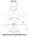
- Fig. 3shows a state wherein the viewer 5 is located just in front of the display screen
- Fig. 4shows a state wherein the viewer 5 moves to the right or left.
- the lenticular lens 2Ais enlarged and the viewer 5 is reduced in scale for the sake of convenience.
- Fig. 3simultaneously shows the relationship between Figs. 1 and 2.
- a right eye light beam emerging from the R pixel 1ais incident on the right eye of the viewer 5, and a left eye light beam emerging from the L pixel 1b is incident on the left eye, thus achieving stereoscopic viewing.
- Fig. 3shows a state wherein the viewer 5 is located just in front of the display screen
- Fig. 4shows a state wherein the viewer 5 moves to the right or left.
- the lenticular lens 2Ais enlarged and the viewer 5 is reduced in scale for the sake of convenience.
- Fig. 3simultaneously shows the relationship between Figs. 1 and 2.
- a right eye light beam emerging from the R pixel 1ais incident on
- the combined image 1can be controlled to have the same array of pixels as that shown in Fig. 3.
- the combined image 1can be controlled to have the same array of pixels as that shown in Fig. 4, thus assuring stereoscopic viewing. More specifically, a binocular or head position of the viewer 5 is detected to control the array of pixels on the combined image 1, so that stereoscopic viewing can be attained even if the viewer 5 moves.
- Figs. 5(A) and 5(B)show top views of the arrangement of the projection type display. More specifically, Fig. 5(A) shows an arrangement of a projection display with a front projection screen, and Fig. 5(B) shows an arrangement of a projection display with a back projection screen.
- reference numeral 11denotes a lenticular lens sheet; 12, a diffusive layer arranged on the rear surface of the lenticular lens sheet; 13, a projector for projecting a right eye image toward the lenticular lens sheet; 14, a projector for projecting a left eye image; and 15, a viewer.
- the projectors 13 and 14 and the viewer 15have the following relationship. That is, the projectors 13 and 14 are arranged immediately above or below the two eyes of the viewer 15.
- the projectors 13 and 14respectively project right and left eye images onto the lenticular lens sheet 11
- light beams emerging from the projectors 13 and 14are reflected by the diffusive layer 12 on the rear surface of the lenticular lens sheet 11 and are returned along the perpendiculars including the projectors.
- the light beam projected from the projector 13reaches the right eye of the viewer 15, and the light beam projected from the projector 14 reaches the left eye of the viewer 15.
- the viewercan view a stereoscopic image on the lenticular lens sheet. More specifically, an image projected from the projectors is focused on the diffusive layer arranged on the rear surface of the lenticular lens sheet as a combined image consisting of R and L pixels, and the viewer stereoscopically views the focused image through the lenticular lens sheet, as shown in Fig. 4.
- two lenticular lens sheetsare in tight contact with each other to sandwich the diffusive layer 12 therebetween.
- the projectors 13 and 14 and the viewer 15are symmetrically arranged with respect to the lenticular lens sheets.
- the light beam emerging from the projector 13passes through the lenticular lens sheets 11 and then reaches the right eye of the viewer 15, as indicated by dotted lines, and the light beam emerging from the projector 14 reaches the left eye of the viewer, as indicated by solid lines.
- the viewercan view a stereoscopic image in the same manner as in the projection display shown in Fig. 5(A).
- Fig. 6is a block diagram showing an arrangement of the direct viewing type display.
- reference numerals 21 and 22denote right and left eye signal sources of a binocular disparity signal source; 23, a multiplex circuit of binocular signals; 24, a binocular position detective circuit for detecting the binocular position of the viewer 5 shown in Figs. 2 to 4; 25, a right and left image array control circuit for controlling an array of a combined image formed on a stereoscopic display device; and 26, a stereoscopic display device.
- the display device 26corresponds to a combination of a lenticular lens sheet and a substantially flat liquid-crystal display device.
- the right and left image array control circuit 25forms a signal for controlling an array of a combined image on the display device based on a binocular position signal as an output from the binocular or head position detective circuit 24 which detects the binocular or head position of the viewer, and applies the signal to the multiplex circuit 23 to control a combination of the binocular signals.
- the resultant signalis applied to the stereoscopic display device 26 to control an array of R and L pixels on the combined image 1, as shown in Fig. 3 or 4. Therefore, the viewer can enjoy stereoscopic viewing even if he moves to the right or left.
- Fig. 7is a block diagram showing the projection type display.
- reference numeral 31denotes a projector for projecting a right eye signal
- 32a projector for projecting a left eye signal
- 33a switch unit for switching the right and left eye signal sources
- 34a binocular or head position detective circuit
- 35a selector for controlling the switching operation of the switch unit 33
- Ra right eye signal input terminal
- La left eye signal input terminal.
- Right and left eye signals from the binocular disparity signal sourcesuch as a television camera, a video disk player, a video tape recorder (VTR), or the like are input to the terminals R and L, respectively.
- the selector 35selects signals to be input to the two projectors 31 and 32 on the basis of the binocular position signal from the binocular or head position detective circuit 34 which detects the binocular or head position of the viewer, and controls the switch unit 33. For example, when the viewer 5 is located at the central position, as shown in Fig.
- the signal at the terminal Ris input to the projector 31 and the signal at the terminal L is input to the projector 32, so that R and L pixels are arrayed on the combined image 1 in the order shown in Fig. 3.
- the selector 35controls the switch unit 33 to switch the input signals to the projectors 31 and 32, so that R and L pixels are arrayed on the combined image in the order, as shown in Fig. 4. Therefore, the viewer can enjoy stereoscopic viewing even if he moves to the right or left.
- a method of assuring stereoscopic viewing on the entire surface of a display over the viewing distance of a stereoscopic image by adhering a lenticular lens sheet on a substantially flat surface of the displaywill be described below.
- Fig. 8is a view for explaining the above-mentioned problems of the present invention.
- lenticular lensesare illustrated as convex lenses.
- the thickness of each lenticular lenscorresponds to a product of the refractive index of the lenticular lens and a focal length f′ of a convex lens.
- reference numeral 51denotes a combined image consisting of pixels 51-a for a right eye image (R pixels) and pixels 51-b for a left eye image (L pixels) to display a two-eye scheme stereoscopic image.
- the length of each R (L) pixelis represented by l
- a repetitive pitch of pairs of R and L pixelsis represented by 2l.
- Reference numeral 52denotes a convex lens sheet constituted by a large number of convex lenses 52A.
- a pitch of the convex lenses 52Ais represented by P, and a focal length is represented by f .
- Reference numeral 53denotes a viewer who is located right in front of a display screen, and views an image at a distance D from the convex lenses 52A (although the two eyes are located farther than the position corresponding to the distance D for the sake of illustrative convenience, they are present at the position of the distance D, in practice.)
- the R (L) pixelis projected to have a size e at the stereoscopic viewing distance D.
- the pitch 2l of the pairs of R and L pixelsis equal to the pitch P of the convex lenses.
- an R pixel 51-a1 of a pair of central R and L pixels(51-a1 and 51-b1) is projected to a right eye 53a of the viewer 53 at the position of the distance D, and the L pixel 51-b1 is projected to a left eye 53b, thus allowing stereoscopic viewing.
- the R pixel 51-a mis projected to the left eye 53b of the viewer 53
- the L pixel 51-b mis projected to neither eyes, thus disturbing stereoscopic viewing.
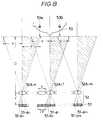
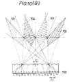
- Fig. 9shows an embodiment of the present invention and is used to explain optical characteristics of the convex lenses 52A and the combined image 51 capable of stereoscopic viewing on the entire display screen.
- Fig. 9illustrates lenticular lenses as convex lenses as in Fig. 8.
- the viewer 53is located just in front of the display screen, and views an image at the distance D from the convex lenses 52A.
- the two eyes 53a and 53bare located farther than the position corresponding to the distance D for the illustrative convenience in Fig. 9 as in Fig. 8, the two eyes are located at the position of the distance D in practice.
- the pitch P of the convex lenses 52Ais set to be slightly smaller than the pitch 2l of the pair of R and L pixels, so that centers 50 of all the pairs of R and L pixels are projected to a center 55 between the two eyes at the distance D.
- the pitch 2l of the pairs of R and L pixelsis 0.4 mm
- the stereoscopic viewing distance Dis 500 mm
- the focal length f ′ of the convex lensis 1.56 mm
- the pitch P of the convex lenses allowing stereoscopic viewing on the entire screenis about 0.3988 mm.
- An average interval between the two eyes of a personis about 64 mm. Therefore, when the R or L pixel is enlarged and projected in a size approximate to the interval between the two eyes of a person, a maximum visible area can be obtained and the viewer can enjoy stereoscopic viewing over the entire screen of the display.
- This methodcan be applied to either of the direct viewing and projection type displays.
- each of L and R pixels corresponding to one lenticular lensis constituted by one pixel.
- the binocular position of the vieweris detected to switch the positions of the R and L pixels on the combined image, thus continuously allowing stereoscopic viewing.
- an area incapable of stereoscopic viewingis formed.
- each of L and R pixels corresponding to one lenticular lensis constituted by a plurality of micropixels (e.g., two micropixels for each of R and L pixels; a total of four micropixels), an area capable of stereoscopic viewing can be expanded.
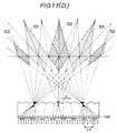
- Fig. 10shows a case wherein one pitch of the lenticular lenses corresponds to a pair of R and L pixels each including one pixel, and is equal to the case of Fig. 9.
- reference symbol Pdenotes a pitch of the lenticular lenses
- fa focal length of the lenticular lens
- Da stereoscopic viewing distance
- 2la pitch of pairs of R and L pixels, which is slightly larger than the pitch P of the lenticular lenses.
- Reference symbol edenotes a stereoscopic visible area almost corresponding to an interval between the two eyes of the viewer.
- Reference numeral 101denotes areas capable of viewing of the R pixels; and 102, areas capable of viewing of the L pixels.
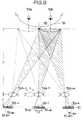
- Fig. 11shows an embodiment for expanding an area capable of stereoscopic viewing, and shows a case wherein one pitch of the lenticular lenses corresponds to a pair of R and L pixels each constituted by two pixels. If two R pixels are represented by R1 and R2 and two L pixels are represented by L1 and L2, four combinations of arrays, i.e., R1-R2-L1-L2, L1-L2-R1-R2, L2-R1-R2-L1, and R2-L1-L2-R1 can be obtained. The four combinations of arrays are shown in Figs. 11(A) 11(B), 11(C) and 11(D). Ranges of the areas 101 and 102 differ depending on the four combinations of arrays.
- the ranges of the areas 101 and 102are expanded up to the ranges added with the ranges shown in Figs. 11(A) 11(B), 11(C) and 11(D). More specifically, even if the viewer moves to the right or left while his two eyes are offset forward or backward from the position of the stereoscopic viewing distance D, the binocular position of the viewer is detected to switch the four combinations of arrays, thus continuously assuring stereoscopic viewing.
Landscapes
- Physics & Mathematics (AREA)
- Engineering & Computer Science (AREA)
- Multimedia (AREA)
- Signal Processing (AREA)
- General Physics & Mathematics (AREA)
- Optics & Photonics (AREA)
- Testing, Inspecting, Measuring Of Stereoscopic Televisions And Televisions (AREA)
- Stereoscopic And Panoramic Photography (AREA)
Description
- The present invention relates to a technique of stereoscopic image display applicable to stereoscopic television sets, stereoscopic video recorders/players, stereoscopic videotelephones for performing communications at remote locations, and the like.
- Techniques of displaying a stereoscopic image (three-dimensional image) include a glass scheme using specific glasses, and a lenticular scheme using a lenticular lens sheet. In the glass scheme, a scheme of displaying a stereoscopic image using polarized glasses, liquid-crystal shutter glasses, or an anaglyph scheme is known. In the glass scheme, a viewer of a stereoscopic image feels unnatural and uneasy since he or she must wear glasses. Especially, for stereoscopic videotelephones with which viewers make conversations while watching each other, since images wearing glasses are displayed, naturalness is considerably impaired.
- On the other hand, a technique of displaying a stereoscopic image by the lenticular scheme includes a direct viewing type wherein a lenticular lens sheet is arranged on the surface of a display such as a CRT, a liquid-crystal display, or the like, and a projection type for projecting an image on a lenticular lens sheet using a projector.
- With the lenticular scheme, a viewer can watch a stereoscopic image without wearing glasses. However, in order to assure stereoscopic viewing in a wide range, a large number of images projected from 6 to 8 places are required, and the arrangement of an apparatus becomes complicated and the apparatus becomes expensive. As a technique for realizing such a lenticular scheme by images projected from two places, a technique for mechanically tracking a head portion is known (e.g., Alfred Schwartz; "Head Tracking Display" IEEE Trans. ED-33, 8 (Aug, 1986)). However, a tracking speed cannot be increased due to mechanical tracking.
- It is an object of the present invention to provide a technique of stereoscopic image display which can assure electronic stereoscopic viewing within a wide range without using glasses.
- It is another object of the present invention to provide a technique which can eliminate a drawback that a discontinuous stereoscopic image is formed when a viewer moves his or her head, and which can continuously and naturally display a stereoscopic image and can expand an area capable of stereoscopic viewing.
- It is still another object of the present invention to provide a technique which can assure stereoscopic viewing within a wide range regardless of whether the direct viewing or projection type display is employed.
- According to the present invention, when a stereoscopic image is viewed using a lenticular lens sheet for viewing a combined image obtained by combining pixels for right and left eye images each having a binocular disparity, the binocular position of a viewer is detected by a detection means so that the pixel for the left eye image is always incident on the left eye and the pixel for the right eye image is always incident on the right eye, and the positions of the pixels for the right and left eye images on the combined image are changed on the basis of the detection signal according to the binocular position of the viewer.
- More specifically, when the direct viewing type display is employed, right and left eye images displayed by a display device such as a liquid-crystal display are controlled by detecting the binocular position of the viewer. When the projection type display is employed, a right or left eye image signal which is input to a corresponding one of two (or a plurality of sets of) projectors is controlled by detecting the binocular position of the viewer.
- According to the present invention, in order to allow stereoscopic viewing of the entire display screen, the pitch of each lenticular lens is set to be slightly smaller than the repetitive pitch of a pair of pixels for right and left eye images on the combined image, so that the centers of all the pairs of pixels for the right and left eye images are projected to the center of the two eyes.
- Furthermore, according to the present invention, each pixel of a pair of pixels for right and left eye images corresponding to one pitch of the lenticular lens is constituted by a plurality of micropixels, and the positions of pixels for the right and left eye images on the combined image are changed in units of micropixels, thus expanding an area capable of stereoscopic viewing.
- Figs. 1 to 4 show the principle of the present invention, in which
- Fig. 1 is a view showing a state near a display screen,
- Fig. 2 is a view showing a state near a viewer,
- Fig. 3 is a view simultaneously showing states near the display screen and the viewer when the viewer is just in front of the display screen, and
- Fig. 4 is a view simultaneously showing states near the display screen and the viewer when the viewer moves to the right or left from the front position;
- Figs. 5(A) and 5(B) show an arrangement and principle of a projection type display, in which
- Fig. 5(A) shows a projection display with a front projection screen, and Fig. 5(B) shows a projection display with a back projection screen;
- Fig. 6 is a block diagram showing an arrangement of a direct viewing type display according to an embodiment of the present invention;
- Fig. 7 is a block diagram showing an arrangement of a projection type display;
- Fig. 8 is a view for explaining a problem posed when a pitch of a lenticular lens is equal to a pitch of a pair of pixels for right and left eye images;
- Fig. 9 is a view for explaining optical characteristics of an embodiment which assures stereoscopic viewing of the entire display screen according to the present invention;
- Figs. 10(A) and 10(B) are views showing areas capable of stereoscopic viewing when a pair of of pixels for right and left eye images correspond to one lenticular lens; and
- Figs. 11(A) to 11(D) are views showing areas capable of stereoscopic viewing when each of pixels for right and left eye images is constituted by two micropixels in correspondence with one lenticular lens in order to expand the areas capable of stereoscopic viewing.
- The present invention will now be described in detail with reference to the accompanying drawings.
- Figs. 1 to 4 are views for explaining the principle of the present invention. Fig. 1 shows a state near a display screen (direct viewing type) or a diffusive layer (projection type). In Fig. 1,
reference numeral 1 denotes a combined image obtained by combining pixels for a left eye image (to be referred to as L pixels hereinafter) and pixels for a right eye image (to be referred to as R pixels hereinafter). Each pair of R and L pixels correspond to each oflenticular lenses 2A constituting alenticular lens sheet 2. The combinedimage 1 is formed on a focal plane of thelenticular lenses 2A. A light beam passing through the centrallenticular lens 2A will be explained below. Light emerging from the right end of anR pixel 1a located immediately below the centrallenticular lens 2A is incident on thelenticular lens 2A at an angle α₁. Similarly, light emerging from the left end of anL pixel 1b is incident on thelenticular lens 2A at the same angle α₁. These light beams comply with the law of refraction expressed by the following equation when they emerge from thelenticular lens 2A:
where β₁ is the emerging angle, andn is the refractive index of thelenticular lens 2A. In this arrangement, when the position of a viewer is set so that the extending line of a perpendicular A of the combinedimage 1 passes through the center between the two eyes of the viewer, the viewer can enjoy stereoscopic viewing. Since the R and L pixels are arranged adjacent to each other, light beams which are incident at an angle α₂ and emerge at an angle β₂ are present outside the light beams emerging from the R andL pixels - Fig. 2 shows the above-mentioned state as well as the viewer. In Fig. 2, when a
viewer 5 is located at the central position indicated by a solid line, since light beams emerging at the angle β₁ are incident on his or her two eyes, he can enjoy stereoscopic viewing. However, when theviewer 5 moves to the right or left and is located at a position indicated by a broken line, light components corresponding to L pixels are incident on the right eye and light components corresponding to R pixels are incident of the left eye, so that stereoscopic view cannot be assured. Thus, when theviewer 5 moves to the position indicated by the broken line, if the positions of the R and L pixels on the combinedimage 1 are reversed, stereoscopic viewing is assured. - Fig. 3 shows a state wherein the
viewer 5 is located just in front of the display screen, and Fig. 4 shows a state wherein theviewer 5 moves to the right or left. In Figs. 3 and 4, thelenticular lens 2A is enlarged and theviewer 5 is reduced in scale for the sake of convenience. Fig. 3 simultaneously shows the relationship between Figs. 1 and 2. A right eye light beam emerging from theR pixel 1a is incident on the right eye of theviewer 5, and a left eye light beam emerging from theL pixel 1b is incident on the left eye, thus achieving stereoscopic viewing. In Fig. 4, when theviewer 5 moves to the right or left and emerging light beams at the angles β₁ and β₂ are incident on two eyes, if the R and L pixels on the combinedimage 1 are reversed to those shown in Fig. 3, light components corresponding to R and L pixels are respectively incident on the right and left eyes of theviewer 5, thus achieving stereoscopic viewing. In order to reverse the R and L pixels on the combinedimage 1, right and left eye signals input to display elements of a display device can be reversed in a direct viewing type display. On the other hand, in a projection type display, right and left eye image signals input to projectors are reversed. When theobserver 5 further moves to the right or left and light beams at angles β₂ and β₃ are incident on the two eyes of theviewer 5, the combinedimage 1 can be controlled to have the same array of pixels as that shown in Fig. 3. When the viewer further moves to a position where he or she receives still outer light beams, the combinedimage 1 can be controlled to have the same array of pixels as that shown in Fig. 4, thus assuring stereoscopic viewing. More specifically, a binocular or head position of theviewer 5 is detected to control the array of pixels on the combinedimage 1, so that stereoscopic viewing can be attained even if theviewer 5 moves. - Note that a technique for detecting the binocular or head position of the viewer is known to those who are skilled in the art (reference: Proc. of SPIE, Visual Communication and Image Processing, 1988, Vo. 1001, K. OHMURA et al.), and a binocular or head position detective equipment is commercially available (e.g., infrared sensor: E₃SA-DS50C₄₃A available from OMRON TATEISHI ELECTRONICS CO., ultrasonic sensor: PS₁-D₁MN available from FUJI ELECTRIC CO., LTD., and the like.)
- The arrangement and principle of the projection type display will be described below.
- Figs. 5(A) and 5(B) show top views of the arrangement of the projection type display. More specifically, Fig. 5(A) shows an arrangement of a projection display with a front projection screen, and Fig. 5(B) shows an arrangement of a projection display with a back projection screen. In Figs. 5(A) and 5(B),
reference numeral 11 denotes a lenticular lens sheet; 12, a diffusive layer arranged on the rear surface of the lenticular lens sheet; 13, a projector for projecting a right eye image toward the lenticular lens sheet; 14, a projector for projecting a left eye image; and 15, a viewer. - In the projection display with the front projection screen shown in Fig. 5(A), the
projectors viewer 15 have the following relationship. That is, theprojectors viewer 15. When theprojectors lenticular lens sheet 11, light beams emerging from theprojectors diffusive layer 12 on the rear surface of thelenticular lens sheet 11 and are returned along the perpendiculars including the projectors. Thus, as indicated by dotted lines, the light beam projected from theprojector 13 reaches the right eye of theviewer 15, and the light beam projected from theprojector 14 reaches the left eye of theviewer 15. As a result, the viewer can view a stereoscopic image on the lenticular lens sheet. More specifically, an image projected from the projectors is focused on the diffusive layer arranged on the rear surface of the lenticular lens sheet as a combined image consisting of R and L pixels, and the viewer stereoscopically views the focused image through the lenticular lens sheet, as shown in Fig. 4. - In the projection display with the back projection screen shown in Fig. 5(B), two lenticular lens sheets are in tight contact with each other to sandwich the
diffusive layer 12 therebetween. Theprojectors viewer 15 are symmetrically arranged with respect to the lenticular lens sheets. With this arrangement, when theprojector 13 projects a right eye image and theprojector 14 projects a left eye image, the light beam emerging from theprojector 13 passes through thelenticular lens sheets 11 and then reaches the right eye of theviewer 15, as indicated by dotted lines, and the light beam emerging from theprojector 14 reaches the left eye of the viewer, as indicated by solid lines. Thus, the viewer can view a stereoscopic image in the same manner as in the projection display shown in Fig. 5(A). - The above description has been made for a case wherein two projectors are used. Of course, more than two projectors may be used to project images.
- Note that the principle of these projectors is known to those who are skilled in the art, and a detailed description thereof will be omitted (reference: "Three-Dimensional Image Optics", T. OHKOSHI, Sangyo Tosho Shuppan, Co.)
- The arrangement of an embodiment of the present invention using the principle shown in Figs. 1 to 5(B) will be described below.
- Fig. 6 is a block diagram showing an arrangement of the direct viewing type display. In Fig. 6,
reference numerals viewer 5 shown in Figs. 2 to 4; 25, a right and left image array control circuit for controlling an array of a combined image formed on a stereoscopic display device; and 26, a stereoscopic display device. Thedisplay device 26 corresponds to a combination of a lenticular lens sheet and a substantially flat liquid-crystal display device. - The operation of the system with the above arrangement will be described below. Signals from the right and left
signal sources multiplex circuit 23. In this case, the right and left imagearray control circuit 25 forms a signal for controlling an array of a combined image on the display device based on a binocular position signal as an output from the binocular or headposition detective circuit 24 which detects the binocular or head position of the viewer, and applies the signal to themultiplex circuit 23 to control a combination of the binocular signals. The resultant signal is applied to thestereoscopic display device 26 to control an array of R and L pixels on the combinedimage 1, as shown in Fig. 3 or 4. Therefore, the viewer can enjoy stereoscopic viewing even if he moves to the right or left. - Fig. 7 is a block diagram showing the projection type display. In Fig. 7,
reference numeral 31 denotes a projector for projecting a right eye signal; 32, a projector for projecting a left eye signal; 33, a switch unit for switching the right and left eye signal sources; 34, a binocular or head position detective circuit; 35, a selector for controlling the switching operation of theswitch unit 33; R, a right eye signal input terminal; and L, a left eye signal input terminal. - The operation of the system with the above arrangement will be described below. Right and left eye signals from the binocular disparity signal source such as a television camera, a video disk player, a video tape recorder (VTR), or the like are input to the terminals R and L, respectively. In this case, the
selector 35 selects signals to be input to the twoprojectors position detective circuit 34 which detects the binocular or head position of the viewer, and controls theswitch unit 33. For example, when theviewer 5 is located at the central position, as shown in Fig. 3, the signal at the terminal R is input to theprojector 31 and the signal at the terminal L is input to theprojector 32, so that R and L pixels are arrayed on the combinedimage 1 in the order shown in Fig. 3. When theviewer 5 moves to the right or left and is located, as shown in Fig. 4, theselector 35 controls theswitch unit 33 to switch the input signals to theprojectors - A method of assuring stereoscopic viewing on the entire surface of a display over the viewing distance of a stereoscopic image by adhering a lenticular lens sheet on a substantially flat surface of the display will be described below.
- Fig. 8 is a view for explaining the above-mentioned problems of the present invention. For the sake of illustrative convenience, lenticular lenses are illustrated as convex lenses. The thickness of each lenticular lens corresponds to a product of the refractive index of the lenticular lens and a focal length f′ of a convex lens. In Fig. 8,
reference numeral 51 denotes a combined image consisting of pixels 51-a for a right eye image (R pixels) and pixels 51-b for a left eye image (L pixels) to display a two-eye scheme stereoscopic image. The length of each R (L) pixel is represented by ℓ, and a repetitive pitch of pairs of R and L pixels is represented by 2ℓ.Reference numeral 52 denotes a convex lens sheet constituted by a large number ofconvex lenses 52A. A pitch of theconvex lenses 52A is represented by P, and a focal length is represented byf.Reference numeral 53 denotes a viewer who is located right in front of a display screen, and views an image at a distance D from theconvex lenses 52A (although the two eyes are located farther than the position corresponding to the distance D for the sake of illustrative convenience, they are present at the position of the distance D, in practice.) The R (L) pixel is projected to have a sizee at the stereoscopic viewing distance D. In Fig. 8, the pitch 2ℓ of the pairs of R and L pixels is equal to the pitch P of the convex lenses. In this case, an R pixel 51-a₁ of a pair of central R and L pixels (51-a₁ and 51-b₁) is projected to aright eye 53a of theviewer 53 at the position of the distance D, and the L pixel 51-b₁ is projected to aleft eye 53b, thus allowing stereoscopic viewing. On the other hand, of a pair of R and L pixels (51-am and 51-bm) at the right end portion of the screen, the R pixel 51-am is projected to theleft eye 53b of theviewer 53, and the L pixel 51-bm is projected to neither eyes, thus disturbing stereoscopic viewing. The same applies to a pair of R and L pixels (51-an and 51-bn) at the left end portion of the screen, and stereoscopic viewing is disturbed. That is, if the pitch 2ℓ of the pairs of R and L pixels is set to be equal to the pitch P of theconvex lenses 52A, theviewer 53 cannot enjoy stereoscopic viewing on the entire display screen. - Fig. 9 shows an embodiment of the present invention and is used to explain optical characteristics of the
convex lenses 52A and the combinedimage 51 capable of stereoscopic viewing on the entire display screen. Fig. 9 illustrates lenticular lenses as convex lenses as in Fig. 8. In Fig. 9, theviewer 53 is located just in front of the display screen, and views an image at the distance D from theconvex lenses 52A. Although the twoeyes convex lenses 52A is set to be slightly smaller than the pitch 2ℓ of the pair of R and L pixels, so thatcenters 50 of all the pairs of R and L pixels are projected to acenter 55 between the two eyes at the distance D. The condition to obtain this state is represented by the following equation:
- If the pitch 2ℓ of the pairs of R and L pixels is 0.4 mm, the stereoscopic viewing distance D is 500 mm, and the focal lengthf′ of the convex lens is 1.56 mm, the pitch P of the convex lenses allowing stereoscopic viewing on the entire screen is about 0.3988 mm. The stereoscopic visible areae at the distance D, the focal lengthf′ of the convex lens, and the length ℓ of the R or L pixel satisfy the following equation:

- In equation (2), if f′ = 1.56 mm, D = 500 mm, and ℓ= 0.2 mm, the stereoscopic visible areae is about 64 mm.
- An average interval between the two eyes of a person is about 64 mm. Therefore, when the R or L pixel is enlarged and projected in a size approximate to the interval between the two eyes of a person, a maximum visible area can be obtained and the viewer can enjoy stereoscopic viewing over the entire screen of the display.
- This method can be applied to either of the direct viewing and projection type displays.
- In the above embodiment, each of L and R pixels corresponding to one lenticular lens is constituted by one pixel. In this case, when the viewer moves to the right or left while the distance between the viewer and the lenticular lens sheet remains the same, the binocular position of the viewer is detected to switch the positions of the R and L pixels on the combined image, thus continuously allowing stereoscopic viewing. However, when the viewer moves to the right or left with a forward or backward offset, an area incapable of stereoscopic viewing is formed. When each of L and R pixels corresponding to one lenticular lens is constituted by a plurality of micropixels (e.g., two micropixels for each of R and L pixels; a total of four micropixels), an area capable of stereoscopic viewing can be expanded.
- Fig. 10 shows a case wherein one pitch of the lenticular lenses corresponds to a pair of R and L pixels each including one pixel, and is equal to the case of Fig. 9. In Fig. 10, reference symbol P denotes a pitch of the lenticular lenses;f, a focal length of the lenticular lens; D, a stereoscopic viewing distance; and 2ℓ, a pitch of pairs of R and L pixels, which is slightly larger than the pitch P of the lenticular lenses. Reference symbole denotes a stereoscopic visible area almost corresponding to an interval between the two eyes of the viewer.
Reference numeral 101 denotes areas capable of viewing of the R pixels; and 102, areas capable of viewing of the L pixels. - When the right eye of the viewer is present in an
area 101 and at the same time, his left eye is present in anarea 102, he can enjoy stereoscopic viewing over the entire display screen. Therefore, for example, when the viewer is present at the center of Fig. 10(A) (along an alternate long and short dashed line) and slightly moves forward or backward from the position corresponding to the distance D, stereoscopic viewing over the entire display screen can be assured. When the binocular position of the viewer is at the distance D and the viewer moves to the right or left, the array of the R and L pixels is switched according to the binocular position of the viewer, thus continuously assuring stereoscopic viewing. However, when the viewer moves to the right or left with a forward or backward offset from the position of the stereoscopic viewing distance D, even if the array of a combinedimage 100 is switched, one or both of the right and left eyes fall outside theareas - Fig. 11 shows an embodiment for expanding an area capable of stereoscopic viewing, and shows a case wherein one pitch of the lenticular lenses corresponds to a pair of R and L pixels each constituted by two pixels. If two R pixels are represented by R₁ and R₂ and two L pixels are represented by L₁ and L₂, four combinations of arrays, i.e., R₁-R₂-L₁-L₂, L₁-L₂-R₁-R₂, L₂-R₁-R₂-L₁, and R₂-L₁-L₂-R₁ can be obtained. The four combinations of arrays are shown in Figs. 11(A) 11(B), 11(C) and 11(D). Ranges of the
areas areas - If the number of micropixels constituting each of R and L pixels corresponding to one lenticular lens is increased, ranges capable of stereoscopic viewing can be further expanded over the entire display screen.


Claims (7)
- A method of displaying stereoscopic images for providing right and left eye images to right (53a) and left (53b) eyes of a viewer (53) using a viewing lenticular lens sheet (2, 52) constituted by an array of lenticular lenses (2A, 52A-1, ,52A-n, 52A-m) on which a combined image (51, 100) is obtained by combining pixels (51-a1, 51-b1) for right and left eye images each (R, L) having binocular disparity data, comprising the steps of :
detecting a position of the viewer (53) ; and
exchanging positions of the pixels for the right (R) and left (L) eye images on the combined image (51, 100) in accordance with the detected position of the viewer (53), so that the right and left eye images (R, L) are always correctly provided to the right (53a) and left (53b) eyes of the viewer. - A method according to claim 1, wherein said method is realized by an arrangement in which a repetitive pitch (p) of said lenticular lenses (2A, 52A) of said lenticular lens sheet (2, 52) is set to be smaller than a repetitive pitch (ℓ) of pairs of pixels (51-a1, 51-b1) for the right and left eye images on the combined image (51, 100).
- A method according to claim 1 or 2, wherein one lenticular lens (2A, 52A) corresponds to one pair of pixels for the right and left eye image (R, L) on the combined image (51, 100) and the step of exchanging the positions of the pixels for the right and left eye images (R, L) on the combined image (51, 100) includes the step of replacing the positions of the pixels for the left and right eye images (R, L).
- A method according to claim 1 or 2, wherein each of the pixels for the right and left eye images (R, L) corresponding to one lenticular lens (2A, 52A) is constituted by a plurality of micropixels, and the step of exchanging the positions of the pixels for the right and left eye images (R, L) on the combined image (51, 100) is executed in units of micropixels.
- A method according to any one of claims 2, 3 and 4, wherein the combined image (51, 100) comprises the right and left eye images (R, L) displayed by a display device arranged behing a rear surface of said viewing lenticular lens sheet (2, 52).
- A method according to any one of claims 2, 3 and 4, wherein the combined image (51, 100) comprises an image obtained by focusing the right and left eye images projected from a plurality of projectors (13, 14) (31, 32) arranged on the side of the viewer (15) on a diffusive layer (12) arranged on a rear surface of said viewing lenticular lens sheet (11) by said lenticular lenses of said viewing lenticular lens sheet (11) .
- A method according to any one of claims 2, 3 and 4, wherein the combined image (51, 100) comprises an image obtained by focusing the right and left eye images projected from a plurality of projectors (13, 14) arranged on a side opposite to the viewer (15) with respect to said viewing lenticular lens sheet on a diffusive layer (12) arranged on a rear surface of said viewing lenticular lens sheet (11) by lenticular lenses of a lenticular lens sheet (11) having the same performance as that of said viewing lenticular lens sheet (11).
Applications Claiming Priority (6)
| Application Number | Priority Date | Filing Date | Title |
|---|---|---|---|
| JP63199955AJP2662252B2 (en) | 1988-08-12 | 1988-08-12 | 3D image display device |
| JP199955/88 | 1988-08-12 | ||
| JP258362/88 | 1988-10-15 | ||
| JP63258362AJP2662262B2 (en) | 1988-10-15 | 1988-10-15 | 3D image display device |
| JP1046220AJPH02226139A (en) | 1989-02-27 | 1989-02-27 | Stereoscopic image display device |
| JP46220/89 | 1989-02-27 |
Publications (3)
| Publication Number | Publication Date |
|---|---|
| EP0354851A2 EP0354851A2 (en) | 1990-02-14 |
| EP0354851A3 EP0354851A3 (en) | 1990-12-19 |
| EP0354851B1true EP0354851B1 (en) | 1994-11-30 |
Family
ID=27292544
Family Applications (1)
| Application Number | Title | Priority Date | Filing Date |
|---|---|---|---|
| EP89402262AExpired - LifetimeEP0354851B1 (en) | 1988-08-12 | 1989-08-10 | Technique of stereoscopic image display |
Country Status (4)
| Country | Link |
|---|---|
| US (1) | US4987487A (en) |
| EP (1) | EP0354851B1 (en) |
| KR (1) | KR930010620B1 (en) |
| DE (1) | DE68919582T2 (en) |
Cited By (3)
| Publication number | Priority date | Publication date | Assignee | Title |
|---|---|---|---|---|
| DE102005058586A1 (en)* | 2005-12-04 | 2007-06-14 | Universität Kassel | Reproduction device for autostereoscopic reproduction of three-dimensional representations |
| CN102281454A (en)* | 2010-06-11 | 2011-12-14 | 乐金显示有限公司 | Stereoscopic image display device |
| CN103747236A (en)* | 2013-12-30 | 2014-04-23 | 中航华东光电有限公司 | 3D (three-dimensional) video processing system and method by combining human eye tracking |
Families Citing this family (114)
| Publication number | Priority date | Publication date | Assignee | Title |
|---|---|---|---|---|
| DE4114023A1 (en)* | 1991-04-29 | 1992-11-05 | Siegbert Prof Dr Ing Hentschke | Visual display providing three=dimensional effect without requiring spectacles - directs images from two cameras using electron guns, through slotted mask and onto screen with lens in front having strip prism form |
| JPH05289208A (en)* | 1992-04-15 | 1993-11-05 | Fuji Photo Film Co Ltd | Method and device for recording stereoscopic image |
| US5279912A (en)* | 1992-05-11 | 1994-01-18 | Polaroid Corporation | Three-dimensional image, and methods for the production thereof |
| US5764231A (en)* | 1992-05-15 | 1998-06-09 | Eastman Kodak Company | Method and apparatus for creating geometric depth images using computer graphics |
| US5278608A (en)* | 1992-05-19 | 1994-01-11 | Eastman Kodak Company | Electronically printed depth photography system with improved viewing range |
| US5287437A (en)* | 1992-06-02 | 1994-02-15 | Sun Microsystems, Inc. | Method and apparatus for head tracked display of precomputed stereo images |
| US5311220A (en)* | 1992-06-10 | 1994-05-10 | Dimension Technologies, Inc. | Autostereoscopic display |
| US5715383A (en)* | 1992-09-28 | 1998-02-03 | Eastman Kodak Company | Compound depth image display system |
| JP3311832B2 (en)* | 1992-10-14 | 2002-08-05 | テルモ株式会社 | 3D image display device |
| GB2271903A (en)* | 1992-10-23 | 1994-04-27 | Sharp Kk | Method of and apparatus for making a 3D print |
| WO1994010805A1 (en)* | 1992-11-05 | 1994-05-11 | Perceptual Images | Three dimensional imaging system using shutter and back to back lenticular screen |
| GB2272555A (en)* | 1992-11-11 | 1994-05-18 | Sharp Kk | Stereoscopic display using a light modulator |
| US6011581A (en)* | 1992-11-16 | 2000-01-04 | Reveo, Inc. | Intelligent method and system for producing and displaying stereoscopically-multiplexed images of three-dimensional objects for use in realistic stereoscopic viewing thereof in interactive virtual reality display environments |
| US6556236B1 (en)* | 1992-11-16 | 2003-04-29 | Reveo, Inc. | Intelligent method and system for producing and displaying stereoscopically-multiplexed images of three-dimensional objects for use in realistic stereoscopic viewing thereof in interactive virtual reality display environments |
| EP0687366B1 (en)* | 1993-03-03 | 2000-01-26 | STREET, Graham Stewart Brandon | Method and apparatus for image alignment |
| DE4312918A1 (en)* | 1993-04-14 | 1994-10-20 | Hertz Inst Heinrich | Playback device |
| JPH06311537A (en)* | 1993-04-26 | 1994-11-04 | Sanyo Electric Co Ltd | Projection type video image display device |
| CA2162036A1 (en)* | 1993-05-04 | 1994-11-10 | Angus Duncan Richards | Stereoscopic display unit |
| EP0876065B1 (en)* | 1993-05-05 | 2000-09-13 | ALLIO, Pierre | Autostereoscopic video device |
| FR2705009B1 (en)* | 1993-05-05 | 1995-07-21 | Particulier Editions | Autostereoscopic video device. |
| ES2135582T3 (en)* | 1993-05-24 | 1999-11-01 | Thomson Brandt Gmbh | PROCEDURE FOR GENERATION OF A STEREOSCOPIC IMAGE. |
| US5493427A (en)* | 1993-05-25 | 1996-02-20 | Sharp Kabushiki Kaisha | Three-dimensional display unit with a variable lens |
| US5365370A (en)* | 1993-06-10 | 1994-11-15 | Hudgins J Stephen | Three dimensional viewing illusion with 2D display |
| US5526146A (en)* | 1993-06-24 | 1996-06-11 | International Business Machines Corporation | Back-lighting system for transmissive display |
| DE69417824T4 (en)* | 1993-08-26 | 2000-06-29 | Matsushita Electric Industrial Co., Ltd. | Stereoscopic scanner |
| JP3409810B2 (en)* | 1993-09-09 | 2003-05-26 | ソニー株式会社 | Image output method |
| GB2284068A (en)* | 1993-11-12 | 1995-05-24 | Sharp Kk | Three-dimensional projection display apparatus |
| US5774261A (en)* | 1993-11-19 | 1998-06-30 | Terumo Kabushiki Kaisha | Image display system |
| DE69432283T2 (en)* | 1993-12-01 | 2004-01-22 | Sharp K.K. | Display for three-dimensional images |
| GB2294350A (en)* | 1994-10-21 | 1996-04-24 | Sharp Kk | Light source and display |
| ATE192275T1 (en)* | 1993-12-03 | 2000-05-15 | Terumo Corp | STEREOSCOPIC IMAGE DISPLAY SYSTEM |
| GB2284958A (en)* | 1993-12-14 | 1995-06-21 | Sharp Kk | Laser 3D printer produces autostereoscopic print |
| US5543964A (en)* | 1993-12-28 | 1996-08-06 | Eastman Kodak Company | Depth image apparatus and method with angularly changing display information |
| JPH07218864A (en)* | 1994-02-07 | 1995-08-18 | Terumo Corp | Three-dimensional image display device |
| JPH07222204A (en)* | 1994-02-07 | 1995-08-18 | Terumo Corp | Stereoscopic image display device |
| JPH07226957A (en)* | 1994-02-09 | 1995-08-22 | Terumo Corp | Stereoscopic picture communication equipment |
| JPH07222866A (en)* | 1994-02-09 | 1995-08-22 | Terumo Corp | Stereoscopic image game machine |
| JP3678765B2 (en)* | 1994-03-10 | 2005-08-03 | ソニー株式会社 | Glasses type display device |
| US5543965A (en)* | 1994-05-11 | 1996-08-06 | Nvision Grafix, Inc. | Method and apparatus for autostereoscopic lenticular displays utilizing random dot patterns |
| JP3387624B2 (en)* | 1994-05-20 | 2003-03-17 | キヤノン株式会社 | 3D display device |
| US6011580A (en)* | 1994-06-07 | 2000-01-04 | Terumo Kabushiki Kaisha | Image display apparatus |
| JPH08160556A (en)* | 1994-06-20 | 1996-06-21 | Tomohiko Hattori | Stereoscopic video display device |
| US5475419A (en)* | 1994-06-29 | 1995-12-12 | Carbery Dimensions, Ltd. | Apparatus and method for three-dimensional video |
| JPH08115439A (en)* | 1994-10-13 | 1996-05-07 | Canon Inc | Image data processing device and image reproducing device |
| US5826212A (en)* | 1994-10-25 | 1998-10-20 | Honda Giken Kogyo Kabushiki Kaisha | Current-position map and three dimensional guiding objects displaying device for vehicle |
| US6985168B2 (en)* | 1994-11-14 | 2006-01-10 | Reveo, Inc. | Intelligent method and system for producing and displaying stereoscopically-multiplexed images of three-dimensional objects for use in realistic stereoscopic viewing thereof in interactive virtual reality display environments |
| AUPN003894A0 (en)* | 1994-12-13 | 1995-01-12 | Xenotech Research Pty Ltd | Head tracking system for stereoscopic display apparatus |
| GB2296617A (en)* | 1994-12-29 | 1996-07-03 | Sharp Kk | Observer tracking autosteroscopic display |
| US5724071A (en)* | 1995-01-25 | 1998-03-03 | Eastman Kodak Company | Depth image display on a CRT |
| GB2297876A (en)* | 1995-02-09 | 1996-08-14 | Sharp Kk | Observer tracking autostereoscopic display |
| JP3459721B2 (en)* | 1995-05-22 | 2003-10-27 | キヤノン株式会社 | Stereoscopic image display method and stereoscopic image display device using the same |
| US5936774A (en)* | 1995-08-29 | 1999-08-10 | Street; Graham S. B. | Autostereoscopic display |
| GB2307058A (en)* | 1995-11-13 | 1997-05-14 | Thomson Multimedia Sa | Stereoscopic display with lens,prism and barrier arrays |
| US6859534B1 (en) | 1995-11-29 | 2005-02-22 | Alfred Alasia | Digital anti-counterfeiting software method and apparatus |
| KR100379367B1 (en)* | 1995-12-27 | 2003-06-19 | 엘지전자 주식회사 | Stereoscopic display |
| GB2309609A (en)* | 1996-01-26 | 1997-07-30 | Sharp Kk | Observer tracking autostereoscopic directional display |
| TW413993B (en)* | 1996-03-15 | 2000-12-01 | Sharp Kk | Image display device |
| US6108634A (en)* | 1996-04-12 | 2000-08-22 | Podnar; Paul J. | Computerized optometer and medical office management system |
| JPH09289655A (en)* | 1996-04-22 | 1997-11-04 | Fujitsu Ltd | Stereoscopic image display method, multi-view image input method, multi-view image processing method, stereo image display device, multi-view image input device, and multi-view image processing device |
| AUPO024696A0 (en) | 1996-06-04 | 1996-06-27 | Xenotech Research Pty Ltd | Video display system |
| GB9611939D0 (en)* | 1996-06-07 | 1996-08-07 | Philips Electronics Nv | Stereoscopic image display driver apparatus |
| GB2317734A (en)* | 1996-09-30 | 1998-04-01 | Sharp Kk | Spatial light modulator and directional display |
| KR100403805B1 (en)* | 1996-10-30 | 2003-12-18 | 삼성전자주식회사 | A stereoscopic image processor and a method thereof |
| JP4119484B2 (en)* | 1996-12-18 | 2008-07-16 | ゼーレアール テヒノロギース ゲーエムベーハー | Information three-dimensional display method and apparatus |
| US6157402A (en)* | 1997-02-13 | 2000-12-05 | Torgeson; W. Lee | Autostereoscopic image presentation system using a screen assembly |
| DE69806692T2 (en)* | 1997-05-27 | 2003-03-20 | Sanyo Electric Co., Ltd. | Stereoscopic display device with user tracking system |
| JP3724157B2 (en)* | 1997-10-30 | 2005-12-07 | コニカミノルタホールディングス株式会社 | Video observation device |
| US6710920B1 (en)* | 1998-03-27 | 2004-03-23 | Sanyo Electric Co., Ltd | Stereoscopic display |
| DE19827590C2 (en) | 1998-06-20 | 2001-05-03 | Christoph Grosmann | Method and device for autostereoscopy |
| US6064354A (en) | 1998-07-01 | 2000-05-16 | Deluca; Michael Joseph | Stereoscopic user interface method and apparatus |
| US6859240B1 (en) | 2000-01-27 | 2005-02-22 | Mems Optical Inc. | Autostereoscopic display |
| WO2001020386A2 (en)* | 1999-09-17 | 2001-03-22 | Mems Optical, Inc. | An autostereoscopic display and method of displaying three-dimensional images, especially color images |
| CA2476610A1 (en)* | 2002-02-27 | 2003-09-04 | Geo-Rae Co., Ltd. | Method and system for controlling a stereoscopic camera |
| JP2004258163A (en)* | 2003-02-25 | 2004-09-16 | Nec Corp | Stereoscopic image display device and stereoscopic image display method |
| US7301587B2 (en)* | 2003-02-28 | 2007-11-27 | Nec Corporation | Image display device and portable terminal device using the same |
| JP2004264587A (en)* | 2003-02-28 | 2004-09-24 | Nec Corp | Stereoscopic image display apparatus, portable terminal system and lenticular lens |
| US20050057491A1 (en)* | 2003-08-28 | 2005-03-17 | Eastman Kodak Company | Private display system |
| JP4002875B2 (en)* | 2003-09-16 | 2007-11-07 | 株式会社東芝 | Stereoscopic image display device |
| US7372629B2 (en)* | 2003-11-06 | 2008-05-13 | Nec Corporation | Three-dimensional image display device, portable terminal device, display panel and fly eye lens |
| US20050185711A1 (en)* | 2004-02-20 | 2005-08-25 | Hanspeter Pfister | 3D television system and method |
| JP4227076B2 (en)* | 2004-05-24 | 2009-02-18 | 株式会社東芝 | Display device for displaying stereoscopic image and display method for displaying stereoscopic image |
| JP4652727B2 (en)* | 2004-06-14 | 2011-03-16 | キヤノン株式会社 | Stereoscopic image generation system and control method thereof |
| FR2873459A1 (en)* | 2004-07-23 | 2006-01-27 | Franck Andre Marie Guigan | OPTICAL DEVICE WITH LENTICULAR NETWORK |
| US7830357B2 (en)* | 2004-07-28 | 2010-11-09 | Panasonic Corporation | Image display device and image display system |
| DE102006012059B3 (en)* | 2004-12-11 | 2006-10-26 | Fraunhofer-Gesellschaft zur Förderung der angewandten Forschung e.V. | Three dimensional picture information creation method, e.g. using matrix display, involves screening subpixels with line-by-line picture offset in direction of raster, and selecting multiplex schema for formation of samples |
| DE102004059729B3 (en)* | 2004-12-11 | 2006-04-13 | Fraunhofer-Gesellschaft zur Förderung der angewandten Forschung e.V. | Imaging method for the autostereoscopic generation of three-dimensional image data from scanned sub-pixel extracts from left and right views of an image uses an optical separating grid |
| US7250954B2 (en)* | 2004-12-16 | 2007-07-31 | Palo Alto Research Center, Incorporated | Three-dimensional image rendering devices and methods |
| US20070091037A1 (en)* | 2005-10-21 | 2007-04-26 | Yee-Chun Lee | Energy Efficient Compact Display For Mobile Device |
| US7982728B2 (en)* | 2006-03-27 | 2011-07-19 | Sony Corporation | Display device |
| US7609906B2 (en)* | 2006-04-04 | 2009-10-27 | Mitsubishi Electric Research Laboratories, Inc. | Method and system for acquiring and displaying 3D light fields |
| US20090168165A1 (en)* | 2006-05-17 | 2009-07-02 | Hoffman Anthony L | System and Method for Combined 3-D Imaging and Full Video Using a Single Lenticular Lens Sheet |
| JP5006587B2 (en)* | 2006-07-05 | 2012-08-22 | 株式会社エヌ・ティ・ティ・ドコモ | Image presenting apparatus and image presenting method |
| DE102006031799B3 (en) | 2006-07-06 | 2008-01-31 | Fraunhofer-Gesellschaft zur Förderung der angewandten Forschung e.V. | Method for autostereoscopic display of image information with adaptation to changes in the head position of the viewer |
| DE102007006038B3 (en)* | 2007-02-07 | 2008-08-28 | Fraunhofer-Gesellschaft zur Förderung der angewandten Forschung e.V. | Autostereoscopic image display device for generating a floating real stereo image |
| US10063848B2 (en)* | 2007-08-24 | 2018-08-28 | John G. Posa | Perspective altering display system |
| TWI387316B (en)* | 2008-11-18 | 2013-02-21 | Ind Tech Res Inst | Stereoscopic image displaying apparatus and stereoscopic image displaying method |
| TWI399570B (en)* | 2009-06-10 | 2013-06-21 | Au Optronics Corp | 3d display and 3d display system |
| CN101604070B (en)* | 2009-07-21 | 2014-05-14 | 友达光电股份有限公司 | Stereoscopic display and stereoscopic display system |
| JP2012010085A (en)* | 2010-06-24 | 2012-01-12 | Sony Corp | Three-dimensional display device and control method of three-dimensional display device |
| JP5494283B2 (en)* | 2010-06-24 | 2014-05-14 | ソニー株式会社 | 3D display device and 3D display device control method |
| CN101909219B (en)* | 2010-07-09 | 2011-10-05 | 深圳超多维光电子有限公司 | Stereoscopic display method and tracking stereoscopic display |
| CN101895779B (en)* | 2010-07-23 | 2011-10-05 | 深圳超多维光电子有限公司 | Stereo display method and system |
| KR101729556B1 (en)* | 2010-08-09 | 2017-04-24 | 엘지전자 주식회사 | A system, an apparatus and a method for displaying a 3-dimensional image and an apparatus for tracking a location |
| TWI405676B (en)* | 2010-12-21 | 2013-08-21 | Hiti Digital Inc | Stereoscopic image printing device with enhanced positioning accuracy and related printing method |
| JP5617624B2 (en)* | 2010-12-28 | 2014-11-05 | ソニー株式会社 | Stereoscopic image display device |
| JP5617647B2 (en) | 2011-01-14 | 2014-11-05 | ソニー株式会社 | Stereoscopic image display device |
| JP6032856B2 (en)* | 2011-12-23 | 2016-11-30 | トムソン ライセンシングThomson Licensing | Computer apparatus with power consumption management and method for managing power consumption of computer apparatus |
| CN102630027B (en)* | 2012-02-21 | 2015-04-08 | 京东方科技集团股份有限公司 | Naked eye 3D display method and apparatus thereof |
| JP6380881B2 (en) | 2012-07-31 | 2018-08-29 | Tianma Japan株式会社 | Stereoscopic image display apparatus, image processing apparatus, and stereoscopic image processing method |
| KR101931085B1 (en)* | 2012-09-03 | 2018-12-21 | 삼성디스플레이 주식회사 | Three dimensional image display apparatus |
| KR20160059406A (en) | 2014-11-18 | 2016-05-26 | 삼성전자주식회사 | Wearable device and method for outputting virtual image |
| DE102019111467A1 (en)* | 2019-05-03 | 2020-11-05 | Carl Zeiss Jena Gmbh | Display device and method for the simultaneous display of different images in at least two eyes |
| EP4029014A4 (en)* | 2019-09-13 | 2023-03-29 | Light Field Lab, Inc. | LIGHT FIELD DISPLAY SYSTEM FOR ADULT APPLICATIONS |
| JP7475231B2 (en)* | 2020-07-20 | 2024-04-26 | 京セラ株式会社 | 3D display device |
Family Cites Families (5)
| Publication number | Priority date | Publication date | Assignee | Title |
|---|---|---|---|---|
| JPS5455114A (en)* | 1977-10-11 | 1979-05-02 | Ricoh Co Ltd | Method and device for obtaining stereophonic television picture |
| JPS5787291A (en)* | 1980-11-18 | 1982-05-31 | Sony Corp | Stereoscopic picture indicator |
| NL8202934A (en)* | 1982-07-21 | 1984-02-16 | Philips Nv | DEVICE FOR DISPLAYING THREE-DIMENSIONAL IMAGES. |
| GB8623490D0 (en)* | 1986-09-30 | 1986-11-05 | Bass M L | Display means for stereoscopic images |
| US4852972A (en)* | 1987-06-08 | 1989-08-01 | Wah Lo Allen K | Method of controlling variation of density of images in 3-D pictures |
- 1989
- 1989-08-09USUS07/391,881patent/US4987487A/ennot_activeExpired - Fee Related
- 1989-08-10EPEP89402262Apatent/EP0354851B1/ennot_activeExpired - Lifetime
- 1989-08-10KRKR1019890011420Apatent/KR930010620B1/ennot_activeExpired - Fee Related
- 1989-08-10DEDE68919582Tpatent/DE68919582T2/ennot_activeExpired - Fee Related
Cited By (4)
| Publication number | Priority date | Publication date | Assignee | Title |
|---|---|---|---|---|
| DE102005058586A1 (en)* | 2005-12-04 | 2007-06-14 | Universität Kassel | Reproduction device for autostereoscopic reproduction of three-dimensional representations |
| DE102005058586B4 (en)* | 2005-12-04 | 2009-12-17 | Universität Kassel | Reproduction device for autostereoscopic reproduction of three-dimensional representations |
| CN102281454A (en)* | 2010-06-11 | 2011-12-14 | 乐金显示有限公司 | Stereoscopic image display device |
| CN103747236A (en)* | 2013-12-30 | 2014-04-23 | 中航华东光电有限公司 | 3D (three-dimensional) video processing system and method by combining human eye tracking |
Also Published As
| Publication number | Publication date |
|---|---|
| US4987487A (en) | 1991-01-22 |
| KR930010620B1 (en) | 1993-10-30 |
| EP0354851A3 (en) | 1990-12-19 |
| DE68919582D1 (en) | 1995-01-12 |
| DE68919582T2 (en) | 1995-07-13 |
| EP0354851A2 (en) | 1990-02-14 |
| KR900004212A (en) | 1990-03-27 |
Similar Documents
| Publication | Publication Date | Title |
|---|---|---|
| EP0354851B1 (en) | Technique of stereoscopic image display | |
| US8451326B2 (en) | Three-dimensional television system, and three-dimensional television receiver | |
| US4214257A (en) | Method and color television picture tube for reproducing three-dimensional image | |
| EP0601308B1 (en) | Stereoscopic television display | |
| US5546120A (en) | Autostereoscopic display system using shutter and back-to-back lenticular screen | |
| JP3268586B2 (en) | 3D image display device and shooting recording device | |
| JP3570104B2 (en) | Liquid crystal display | |
| KR20020023227A (en) | Three-dimensional image producing method and apparatus therefor | |
| JPH0775137A (en) | Spectacles for stereoscopic image | |
| JPH0954376A (en) | Stereoscopic display device | |
| WO1983002169A1 (en) | Stereoscopic pictures | |
| US3529082A (en) | Multidimensional electrical-optical transmitting and reproducing system | |
| RU2397524C2 (en) | Camera for recording three-dimensional images | |
| JPH0340692A (en) | Stereoscopic picture display method | |
| JPH0583746A (en) | 3D display device | |
| JPH0713105A (en) | Observer follow-up type stereoscopic display device | |
| JP3500083B2 (en) | 3D image display without glasses | |
| KR20000024767A (en) | Adapter for stereo picture shot device | |
| JPH11164323A (en) | Multi-viewpoint image viewing method and apparatus | |
| JP2001356298A (en) | Stereoscopic video display device | |
| JPH09182113A (en) | Three-dimensional solid video signal conversion device and video camera device using the device | |
| JP3463960B2 (en) | 3D image display device | |
| JPH04242394A (en) | Parallax fusion type stereoscopic picture television telephone set | |
| JPH10253925A (en) | Lens plate having plural focal points, and stereoscopic image display device using it | |
| US9807370B2 (en) | Compact stereoscopic picture taking system |
Legal Events
| Date | Code | Title | Description |
|---|---|---|---|
| PUAI | Public reference made under article 153(3) epc to a published international application that has entered the european phase | Free format text:ORIGINAL CODE: 0009012 | |
| AK | Designated contracting states | Kind code of ref document:A2 Designated state(s):DE FR GB | |
| PUAL | Search report despatched | Free format text:ORIGINAL CODE: 0009013 | |
| AK | Designated contracting states | Kind code of ref document:A3 Designated state(s):DE FR GB | |
| 17P | Request for examination filed | Effective date:19910419 | |
| 17Q | First examination report despatched | Effective date:19930526 | |
| GRAA | (expected) grant | Free format text:ORIGINAL CODE: 0009210 | |
| AK | Designated contracting states | Kind code of ref document:B1 Designated state(s):DE FR GB | |
| REF | Corresponds to: | Ref document number:68919582 Country of ref document:DE Date of ref document:19950112 | |
| ET | Fr: translation filed | ||
| PLBE | No opposition filed within time limit | Free format text:ORIGINAL CODE: 0009261 | |
| STAA | Information on the status of an ep patent application or granted ep patent | Free format text:STATUS: NO OPPOSITION FILED WITHIN TIME LIMIT | |
| 26N | No opposition filed | ||
| REG | Reference to a national code | Ref country code:FR Ref legal event code:CA | |
| PGFP | Annual fee paid to national office [announced via postgrant information from national office to epo] | Ref country code:GB Payment date:19990804 Year of fee payment:11 | |
| PGFP | Annual fee paid to national office [announced via postgrant information from national office to epo] | Ref country code:FR Payment date:19990831 Year of fee payment:11 | |
| PGFP | Annual fee paid to national office [announced via postgrant information from national office to epo] | Ref country code:DE Payment date:19990915 Year of fee payment:11 | |
| PG25 | Lapsed in a contracting state [announced via postgrant information from national office to epo] | Ref country code:GB Free format text:LAPSE BECAUSE OF NON-PAYMENT OF DUE FEES Effective date:20000810 | |
| GBPC | Gb: european patent ceased through non-payment of renewal fee | Effective date:20000810 | |
| PG25 | Lapsed in a contracting state [announced via postgrant information from national office to epo] | Ref country code:FR Free format text:LAPSE BECAUSE OF NON-PAYMENT OF DUE FEES Effective date:20010430 | |
| PG25 | Lapsed in a contracting state [announced via postgrant information from national office to epo] | Ref country code:DE Free format text:LAPSE BECAUSE OF NON-PAYMENT OF DUE FEES Effective date:20010501 | |
| REG | Reference to a national code | Ref country code:FR Ref legal event code:ST |