EP0353087B1 - Atherectomy device - Google Patents
Atherectomy deviceDownload PDFInfo
- Publication number
- EP0353087B1 EP0353087B1EP89307691AEP89307691AEP0353087B1EP 0353087 B1EP0353087 B1EP 0353087B1EP 89307691 AEP89307691 AEP 89307691AEP 89307691 AEP89307691 AEP 89307691AEP 0353087 B1EP0353087 B1EP 0353087B1
- Authority
- EP
- European Patent Office
- Prior art keywords
- flexible
- catheter
- atherectomy system
- obstruction
- rotary
- Prior art date
- Legal status (The legal status is an assumption and is not a legal conclusion. Google has not performed a legal analysis and makes no representation as to the accuracy of the status listed.)
- Expired - Lifetime
Links
- 210000001367arteryAnatomy0.000claimsdescription20
- 239000000463materialSubstances0.000claimsdescription20
- 238000005520cutting processMethods0.000claimsdescription11
- 238000006073displacement reactionMethods0.000claimsdescription7
- 230000008878couplingEffects0.000claimsdescription3
- 238000010168coupling processMethods0.000claimsdescription3
- 238000005859coupling reactionMethods0.000claimsdescription3
- 239000002184metalSubstances0.000claimsdescription3
- 239000013307optical fiberSubstances0.000claimsdescription3
- 230000004888barrier functionEffects0.000claimsdescription2
- 230000002572peristaltic effectEffects0.000claims1
- 230000017531blood circulationEffects0.000description5
- 238000000034methodMethods0.000description5
- 230000008569processEffects0.000description5
- 208000007536ThrombosisDiseases0.000description4
- 239000008280bloodSubstances0.000description4
- 210000004369bloodAnatomy0.000description4
- 239000012530fluidSubstances0.000description4
- 208000010125myocardial infarctionDiseases0.000description4
- 230000009471actionEffects0.000description3
- 238000002399angioplastyMethods0.000description3
- 238000003780insertionMethods0.000description3
- 230000037431insertionEffects0.000description3
- 208000021328arterial occlusionDiseases0.000description2
- 230000001154acute effectEffects0.000description1
- 230000003143atherosclerotic effectEffects0.000description1
- 210000004204blood vesselAnatomy0.000description1
- 238000004891communicationMethods0.000description1
- 210000004351coronary vesselAnatomy0.000description1
- 230000003292diminished effectEffects0.000description1
- 239000003925fatSubstances0.000description1
- 239000002657fibrous materialSubstances0.000description1
- 238000011010flushing procedureMethods0.000description1
- 238000003384imaging methodMethods0.000description1
- 230000007774longtermEffects0.000description1
- 239000002245particleSubstances0.000description1
- 230000001105regulatory effectEffects0.000description1
- 230000004044responseEffects0.000description1
- 230000007480spreadingEffects0.000description1
- 229910001220stainless steelInorganic materials0.000description1
- 239000010935stainless steelSubstances0.000description1
- 230000001360synchronised effectEffects0.000description1
Images
Classifications
- A—HUMAN NECESSITIES
- A61—MEDICAL OR VETERINARY SCIENCE; HYGIENE
- A61B—DIAGNOSIS; SURGERY; IDENTIFICATION
- A61B17/00—Surgical instruments, devices or methods
- A61B17/32—Surgical cutting instruments
- A61B17/3205—Excision instruments
- A61B17/3207—Atherectomy devices working by cutting or abrading; Similar devices specially adapted for non-vascular obstructions
- A—HUMAN NECESSITIES
- A61—MEDICAL OR VETERINARY SCIENCE; HYGIENE
- A61B—DIAGNOSIS; SURGERY; IDENTIFICATION
- A61B17/00—Surgical instruments, devices or methods
- A61B17/22—Implements for squeezing-off ulcers or the like on inner organs of the body; Implements for scraping-out cavities of body organs, e.g. bones; for invasive removal or destruction of calculus using mechanical vibrations; for removing obstructions in blood vessels, not otherwise provided for
- A61B17/22004—Implements for squeezing-off ulcers or the like on inner organs of the body; Implements for scraping-out cavities of body organs, e.g. bones; for invasive removal or destruction of calculus using mechanical vibrations; for removing obstructions in blood vessels, not otherwise provided for using mechanical vibrations, e.g. ultrasonic shock waves
- A61B17/22012—Implements for squeezing-off ulcers or the like on inner organs of the body; Implements for scraping-out cavities of body organs, e.g. bones; for invasive removal or destruction of calculus using mechanical vibrations; for removing obstructions in blood vessels, not otherwise provided for using mechanical vibrations, e.g. ultrasonic shock waves in direct contact with, or very close to, the obstruction or concrement
- A—HUMAN NECESSITIES
- A61—MEDICAL OR VETERINARY SCIENCE; HYGIENE
- A61B—DIAGNOSIS; SURGERY; IDENTIFICATION
- A61B17/00—Surgical instruments, devices or methods
- A61B17/32—Surgical cutting instruments
- A61B17/3205—Excision instruments
- A61B17/3207—Atherectomy devices working by cutting or abrading; Similar devices specially adapted for non-vascular obstructions
- A61B17/320758—Atherectomy devices working by cutting or abrading; Similar devices specially adapted for non-vascular obstructions with a rotating cutting instrument, e.g. motor driven
- A—HUMAN NECESSITIES
- A61—MEDICAL OR VETERINARY SCIENCE; HYGIENE
- A61B—DIAGNOSIS; SURGERY; IDENTIFICATION
- A61B17/00—Surgical instruments, devices or methods
- A61B17/32—Surgical cutting instruments
- A61B17/3205—Excision instruments
- A61B17/3207—Atherectomy devices working by cutting or abrading; Similar devices specially adapted for non-vascular obstructions
- A61B17/320783—Atherectomy devices working by cutting or abrading; Similar devices specially adapted for non-vascular obstructions through side-hole, e.g. sliding or rotating cutter inside catheter
- A—HUMAN NECESSITIES
- A61—MEDICAL OR VETERINARY SCIENCE; HYGIENE
- A61B—DIAGNOSIS; SURGERY; IDENTIFICATION
- A61B18/00—Surgical instruments, devices or methods for transferring non-mechanical forms of energy to or from the body
- A61B18/04—Surgical instruments, devices or methods for transferring non-mechanical forms of energy to or from the body by heating
- A61B18/08—Surgical instruments, devices or methods for transferring non-mechanical forms of energy to or from the body by heating by means of electrically-heated probes
- A61B18/082—Probes or electrodes therefor
- A—HUMAN NECESSITIES
- A61—MEDICAL OR VETERINARY SCIENCE; HYGIENE
- A61B—DIAGNOSIS; SURGERY; IDENTIFICATION
- A61B18/00—Surgical instruments, devices or methods for transferring non-mechanical forms of energy to or from the body
- A61B18/18—Surgical instruments, devices or methods for transferring non-mechanical forms of energy to or from the body by applying electromagnetic radiation, e.g. microwaves
- A61B18/20—Surgical instruments, devices or methods for transferring non-mechanical forms of energy to or from the body by applying electromagnetic radiation, e.g. microwaves using laser
- A61B18/22—Surgical instruments, devices or methods for transferring non-mechanical forms of energy to or from the body by applying electromagnetic radiation, e.g. microwaves using laser the beam being directed along or through a flexible conduit, e.g. an optical fibre; Couplings or hand-pieces therefor
- A61B18/24—Surgical instruments, devices or methods for transferring non-mechanical forms of energy to or from the body by applying electromagnetic radiation, e.g. microwaves using laser the beam being directed along or through a flexible conduit, e.g. an optical fibre; Couplings or hand-pieces therefor with a catheter
- A61B18/245—Surgical instruments, devices or methods for transferring non-mechanical forms of energy to or from the body by applying electromagnetic radiation, e.g. microwaves using laser the beam being directed along or through a flexible conduit, e.g. an optical fibre; Couplings or hand-pieces therefor with a catheter for removing obstructions in blood vessels or calculi
- F—MECHANICAL ENGINEERING; LIGHTING; HEATING; WEAPONS; BLASTING
- F16—ENGINEERING ELEMENTS AND UNITS; GENERAL MEASURES FOR PRODUCING AND MAINTAINING EFFECTIVE FUNCTIONING OF MACHINES OR INSTALLATIONS; THERMAL INSULATION IN GENERAL
- F16C—SHAFTS; FLEXIBLE SHAFTS; ELEMENTS OR CRANKSHAFT MECHANISMS; ROTARY BODIES OTHER THAN GEARING ELEMENTS; BEARINGS
- F16C1/00—Flexible shafts; Mechanical means for transmitting movement in a flexible sheathing
- F16C1/02—Flexible shafts; Mechanical means for transmitting movement in a flexible sheathing for conveying rotary movements
- F—MECHANICAL ENGINEERING; LIGHTING; HEATING; WEAPONS; BLASTING
- F16—ENGINEERING ELEMENTS AND UNITS; GENERAL MEASURES FOR PRODUCING AND MAINTAINING EFFECTIVE FUNCTIONING OF MACHINES OR INSTALLATIONS; THERMAL INSULATION IN GENERAL
- F16D—COUPLINGS FOR TRANSMITTING ROTATION; CLUTCHES; BRAKES
- F16D7/00—Slip couplings, e.g. slipping on overload, for absorbing shock
- F16D7/02—Slip couplings, e.g. slipping on overload, for absorbing shock of the friction type
- A—HUMAN NECESSITIES
- A61—MEDICAL OR VETERINARY SCIENCE; HYGIENE
- A61B—DIAGNOSIS; SURGERY; IDENTIFICATION
- A61B18/00—Surgical instruments, devices or methods for transferring non-mechanical forms of energy to or from the body
- A61B18/18—Surgical instruments, devices or methods for transferring non-mechanical forms of energy to or from the body by applying electromagnetic radiation, e.g. microwaves
- A61B18/20—Surgical instruments, devices or methods for transferring non-mechanical forms of energy to or from the body by applying electromagnetic radiation, e.g. microwaves using laser
- A61B18/22—Surgical instruments, devices or methods for transferring non-mechanical forms of energy to or from the body by applying electromagnetic radiation, e.g. microwaves using laser the beam being directed along or through a flexible conduit, e.g. an optical fibre; Couplings or hand-pieces therefor
- A61B18/24—Surgical instruments, devices or methods for transferring non-mechanical forms of energy to or from the body by applying electromagnetic radiation, e.g. microwaves using laser the beam being directed along or through a flexible conduit, e.g. an optical fibre; Couplings or hand-pieces therefor with a catheter
- A—HUMAN NECESSITIES
- A61—MEDICAL OR VETERINARY SCIENCE; HYGIENE
- A61B—DIAGNOSIS; SURGERY; IDENTIFICATION
- A61B17/00—Surgical instruments, devices or methods
- A61B17/22—Implements for squeezing-off ulcers or the like on inner organs of the body; Implements for scraping-out cavities of body organs, e.g. bones; for invasive removal or destruction of calculus using mechanical vibrations; for removing obstructions in blood vessels, not otherwise provided for
- A61B2017/22038—Implements for squeezing-off ulcers or the like on inner organs of the body; Implements for scraping-out cavities of body organs, e.g. bones; for invasive removal or destruction of calculus using mechanical vibrations; for removing obstructions in blood vessels, not otherwise provided for with a guide wire
- A—HUMAN NECESSITIES
- A61—MEDICAL OR VETERINARY SCIENCE; HYGIENE
- A61B—DIAGNOSIS; SURGERY; IDENTIFICATION
- A61B90/00—Instruments, implements or accessories specially adapted for surgery or diagnosis and not covered by any of the groups A61B1/00 - A61B50/00, e.g. for luxation treatment or for protecting wound edges
- A61B90/36—Image-producing devices or illumination devices not otherwise provided for
- A61B90/361—Image-producing devices, e.g. surgical cameras
- A61B2090/3614—Image-producing devices, e.g. surgical cameras using optical fibre
- A—HUMAN NECESSITIES
- A61—MEDICAL OR VETERINARY SCIENCE; HYGIENE
- A61B—DIAGNOSIS; SURGERY; IDENTIFICATION
- A61B2217/00—General characteristics of surgical instruments
- A61B2217/002—Auxiliary appliance
- A61B2217/005—Auxiliary appliance with suction drainage system
- A—HUMAN NECESSITIES
- A61—MEDICAL OR VETERINARY SCIENCE; HYGIENE
- A61M—DEVICES FOR INTRODUCING MEDIA INTO, OR ONTO, THE BODY; DEVICES FOR TRANSDUCING BODY MEDIA OR FOR TAKING MEDIA FROM THE BODY; DEVICES FOR PRODUCING OR ENDING SLEEP OR STUPOR
- A61M1/00—Suction or pumping devices for medical purposes; Devices for carrying-off, for treatment of, or for carrying-over, body-liquids; Drainage systems
- A61M1/71—Suction drainage systems
- A61M1/74—Suction control
- A61M1/75—Intermittent or pulsating suction
- F—MECHANICAL ENGINEERING; LIGHTING; HEATING; WEAPONS; BLASTING
- F16—ENGINEERING ELEMENTS AND UNITS; GENERAL MEASURES FOR PRODUCING AND MAINTAINING EFFECTIVE FUNCTIONING OF MACHINES OR INSTALLATIONS; THERMAL INSULATION IN GENERAL
- F16C—SHAFTS; FLEXIBLE SHAFTS; ELEMENTS OR CRANKSHAFT MECHANISMS; ROTARY BODIES OTHER THAN GEARING ELEMENTS; BEARINGS
- F16C2316/00—Apparatus in health or amusement
- F16C2316/10—Apparatus in health or amusement in medical appliances, e.g. in diagnosis, dentistry, instruments, prostheses, medical imaging appliances
Definitions
- This inventionrelates to an atherectomy system for cutting, ingesting and removing an obstruction from within a patient's artery.
- Prior art document EPA 0254414discloses a rotary catheter insertable into a patients blood vessel for cutting ingesting and removing an obstruction therein, the device including suction means to assist the flexible rotary catheter in ingesting the obstruction material.
- An objective of the inventionis to provide an atherectomy catheter rotatable over a flexible guide wire, equipped with a rotary cutting means at its distal end, that would cut and ingest the obstruction material including blood clots if present, create a smooth lumen and not crack the arterial wall.
- a further objective of the present inventionis to provide suction means which will assist the flexible rotary catheter in ingesting the obstruction material.
- the suction meansis a positive displacement pump means.
- the suction meansis self regulating and is used to automatically increase and decrease the suction in response to the presence or the absence, respectively, of obstruction material in the flexible rotary catheter.
- such suction meansreduces the amount of blood removed from the patient and prevents the arterial wall from collapsing in the absence of obstruction material.
- Another objective of the inventionis to provide a system that would lend itself to be produceable in diameters down to around 1mm (millimeter) and a length of up to around a meter, to be able to reach and enter small and remote arteries.
- the operation of the atherectomy systemwould resemble the operation of present catheter systems, so that existing skills of the medical staff can be utilised.
- Figure 1shows the atherectomy system 10 for cutting, ingesting and removing an obstruction 12 from within a patients vessel, an artery 11.
- the atherectomy systemcomprises several elongated parts in a nested relationship, and their ends shall be referred to as “distal”, meaning the end which goes into the artery and "proximal”, meaning the other end. Therefore, “distal direction” or the term “distally” shall indicate a general direction from the proximal end to the distal end, and "proximal direction” or “proximally” shall refer to an opposite direction.
- the atherectomy systemcomprises: A flexible guide-wire 25 which is insertable into the artery.
- the flexible guide-wireis equipped at its distal end 32 with a distal barrier means in the form of a flexible collapsible umbrella 26 to counter distal movement of surrounding obstruction material while the blade cuts the obstruction material.
- the flexible guide-wiremay also contain an optical fibre bundle 41 in a plastic jacket 47 and a lens 33 at its distal tip.
- An imaging unit and/or laser gun 27may be optically coupled to the proximal end of the optical fibre bundle for analysing the inside of the artery and/or opening, respectively, a pilot passage for the distal tip of the flexible guide-wire to pass through in a case of complete arterial blockage.
- a flexible rotary-catheter 13is rotatably disposed and slidable over the flexible guide-wire.
- a stainless steel hollow blade 16is fitted into a distal end 14 of the flexible rotary-catheter.
- the bladehas teeth 18 on its periphery which are bent inwardly, toward the center of the blade, to ease insertion through the arteries and to reduce the chance of cutting the wall of the artery during the insertion and cutting operation.
- a front edge 44 of the teethis sharpened to cut the obstruction material to pieces 12' which pass into a continuous passage 23 through spaces 39 between the teeth while the blade rotates forward in a direction of arrow 46 (note Figure 2).
- a back side of the teeth 45is dull to allow a backwards rotation while manipulating and advancing the flexible rotary-catheter through the arterial system towards the obstruction with a reduced risk of injuring the arterial wall.
- the bladehas an outer wall 16' which slidingly and rotatably bears against the artery spreading the contact force on a relatively large area and thereby minimising the damage to the artery.
- a rotating inner-wall 42is formed by the inside surface of the flexible rotary-catheter.
- the continuous passage 23is defined between the rotating inner-wall and the flexible guide-wire, and the relative motion between the flexible rotary catheter and the flexible guide-wire mechanically acts on the ingested obstruction material in the continuous passage and enables it to move towards the proximal end 15 of the flexible rotary-catheter and make room for additional cut material.
- Coupling means affixed to the proximal end of the flexible rotary-catheter in the form of a hub 22is frictionally engaged with a flat belt 21 which couples the flexible rotary-catheter to a rotating means in the form of a motor 19 having a pulley 20.
- the proximal end of the flexible guide-wireslidingly and rotatably extends through the hub.
- Suctioncan be applied to the proximal end of the flexible rotary catheter by, preferably, a positive displacement type suction pump 17, driven by a motor 17′.
- the suctionis applied through ports 30 which alternately communicate with a port 31 formed in a sleeve 31′, as the hub rotates in the sleeve 31′.
- a groove 28(shown in phantom lines) can provide continuous communication between the continuous passage 23 and the port 31.
- the suctioncooperates with the mechanical action taking place in the continuous passage to move the cut obstruction material 12′ proximally.
- a positive displacement pumpsuch as a piston pump or a peristalic pump tends to self regulate the evacuation process. The amount of blood removed is limited by the volumn that is positively displaced by the pump.
- the negative pressure in the continuous passagewill drop. As obstruction material enters the continuous passage the negative pressure rises and pulls the cut material proximally.
- the level of negative pressurecan be limited by a relief valve in the pump. The action of the pump can be synchronised with the actual cutting action of the blade 16, or otherwise selectively controlled to avoid excessive blood removal.
- the flexible rotary-cathetercan be manufactured with an increased wall thickness and increased torque carrying capacity at the vicinity of its proximal end compared with the same at its distal end (note Figure 1), and the wall can be reinforced by a spiral means in the form of metal ribbon 24 (note Figures 1 and 3).
- the atherectomy systemcan be manufactured in different diameters and lengths depending on the size and site of the artery that it is intended for and on whether the system is to be used percutaneously (that is through the skin) or intraoperatively (that is when the artery is surgically exposed for inserting the system).
- a process for removing an obstruction from an artery with an atherectomy systemcomprises the following steps:
- Fluidcan be delivered to the obstruction site through the flexible sleeve, around the atherectomy catheter.
- Such fluidcan lubricate and cool the cutting process and provide a medium for flushing particles of obstruction material into the atherectomy catheter, especially in conjunction with suction, preferably applied to the proximal end of the atherectomy catheter by a positive displacement pump means.
- the fluidmay be radio-opaque to assist x-raying the process.
- fluidPrior to cutting, fluid can also be delivered through the atherectomy catheter.
- the sequence of insertion of the components into the arterymay vary depending on the nature and location of the obstruction and the preferences of the medical staff. Additional steps may be added to assist the process.
- a standard guiding catheterwhich is either straight or pre-bent, may be inserted into the artery to assist in bringing the flexible guide-wire and the atherectomy catheter to the obstruction site.
- the flexible guide-wirecan usually be inserted through the fresh clot and the atherectomy system, preferably while employing suction, can be used to clear the clot in order to restore blood flow through the artery and alleviate the acute heart attack. Then the system can be utilised to cut the underlying atherosclerotic obstruction providing a long term correction to the condition that induced the attack.
Landscapes
- Health & Medical Sciences (AREA)
- Surgery (AREA)
- Life Sciences & Earth Sciences (AREA)
- Engineering & Computer Science (AREA)
- Veterinary Medicine (AREA)
- Nuclear Medicine, Radiotherapy & Molecular Imaging (AREA)
- General Health & Medical Sciences (AREA)
- Public Health (AREA)
- Animal Behavior & Ethology (AREA)
- Biomedical Technology (AREA)
- Heart & Thoracic Surgery (AREA)
- Medical Informatics (AREA)
- Molecular Biology (AREA)
- Vascular Medicine (AREA)
- General Engineering & Computer Science (AREA)
- Physics & Mathematics (AREA)
- Mechanical Engineering (AREA)
- Otolaryngology (AREA)
- Electromagnetism (AREA)
- Optics & Photonics (AREA)
- Oral & Maxillofacial Surgery (AREA)
- Plasma & Fusion (AREA)
- Orthopedic Medicine & Surgery (AREA)
- Surgical Instruments (AREA)
Description
- This invention relates to an atherectomy system for cutting, ingesting and removing an obstruction from within a patient's artery.
- With age a large percentage of the population developes arterial obstructions formed by fats, fibrous material and calcified deposits, resulting in a diminished blood circulation. The disturbance to blood flow which these obstructions cause may induce blood clots which further diminish or block the blood flow. When this process occurs in the coronary arteries it is referred to as a heart attack. Presently such obstructions are circumvented by surgically grafting a bypass or they are treated by a catheter equipped with a balloon which is inserted through the arterial system, over a flexible guide-wire, into the obstruction and then inflated to expand the obstruction's lumen (angioplasty). Problems with this treatment are that it injures the arterial wall creating a rough lumen and in certain cases it is ineffective. Further, angioplasty does not remove the obstruction material out of the arterial system, therefore in a case of a heart attack, immediate angioplasty carries the risk of dislodging the blood clot and allowing it to move down stream creating additional blockages.
- Prior art document EPA 0254414 discloses a rotary catheter insertable into a patients blood vessel for cutting ingesting and removing an obstruction therein, the device including suction means to assist the flexible rotary catheter in ingesting the obstruction material.
- An objective of the invention is to provide an atherectomy catheter rotatable over a flexible guide wire, equipped with a rotary cutting means at its distal end, that would cut and ingest the obstruction material including blood clots if present, create a smooth lumen and not crack the arterial wall.
- A further objective of the present invention is to provide suction means which will assist the flexible rotary catheter in ingesting the obstruction material.
- In the present invention therefore the suction means is a positive displacement pump means.
- Preferably, the suction means is self regulating and is used to automatically increase and decrease the suction in response to the presence or the absence, respectively, of obstruction material in the flexible rotary catheter. Thereby, such suction means reduces the amount of blood removed from the patient and prevents the arterial wall from collapsing in the absence of obstruction material.
- Another objective of the invention is to provide a system that would lend itself to be produceable in diameters down to around 1mm (millimeter) and a length of up to around a meter, to be able to reach and enter small and remote arteries.
- Preferably, the operation of the atherectomy system would resemble the operation of present catheter systems, so that existing skills of the medical staff can be utilised. These and other objectives of the invention will become apparent from the following discussion and the accompanying drawings.
- In order that the invention may be more fully understood an illustrative embodiment will now be described with reference to the accompanying drawings wherein:
- Figure 1 generally shows a cross sectional view of an atherectomy system according to the present invention;
- Figure 2 shows a distal end of the atherectomy system.
- Figure 3 shows a cross sectional view of the atherectomy system along a line 3-3 marked on Figure 1.
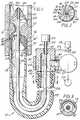
- Figure 1 shows the
atherectomy system 10 for cutting, ingesting and removing anobstruction 12 from within a patients vessel, anartery 11. As shown in Figure 1, the atherectomy system comprises several elongated parts in a nested relationship, and their ends shall be referred to as "distal", meaning the end which goes into the artery and "proximal", meaning the other end. Therefore, "distal direction" or the term "distally" shall indicate a general direction from the proximal end to the distal end, and "proximal direction" or "proximally" shall refer to an opposite direction. - The atherectomy system comprises:
A flexible guide-wire 25 which is insertable into the artery. Optionally, the flexible guide-wire is equipped at itsdistal end 32 with a distal barrier means in the form of a flexiblecollapsible umbrella 26 to counter distal movement of surrounding obstruction material while the blade cuts the obstruction material. The flexible guide-wire may also contain anoptical fibre bundle 41 in aplastic jacket 47 and alens 33 at its distal tip. An imaging unit and/orlaser gun 27 may be optically coupled to the proximal end of the optical fibre bundle for analysing the inside of the artery and/or opening, respectively, a pilot passage for the distal tip of the flexible guide-wire to pass through in a case of complete arterial blockage. - A flexible rotary-
catheter 13 is rotatably disposed and slidable over the flexible guide-wire. - A stainless steel
hollow blade 16 is fitted into adistal end 14 of the flexible rotary-catheter. The blade hasteeth 18 on its periphery which are bent inwardly, toward the center of the blade, to ease insertion through the arteries and to reduce the chance of cutting the wall of the artery during the insertion and cutting operation. Afront edge 44 of the teeth is sharpened to cut the obstruction material to pieces 12' which pass into acontinuous passage 23 throughspaces 39 between the teeth while the blade rotates forward in a direction of arrow 46 (note Figure 2). A back side of theteeth 45 is dull to allow a backwards rotation while manipulating and advancing the flexible rotary-catheter through the arterial system towards the obstruction with a reduced risk of injuring the arterial wall. The blade has an outer wall 16' which slidingly and rotatably bears against the artery spreading the contact force on a relatively large area and thereby minimising the damage to the artery. A rotating inner-wall 42 is formed by the inside surface of the flexible rotary-catheter. - The
continuous passage 23 is defined between the rotating inner-wall and the flexible guide-wire, and the relative motion between the flexible rotary catheter and the flexible guide-wire mechanically acts on the ingested obstruction material in the continuous passage and enables it to move towards theproximal end 15 of the flexible rotary-catheter and make room for additional cut material. - Coupling means affixed to the proximal end of the flexible rotary-catheter in the form of a
hub 22 is frictionally engaged with aflat belt 21 which couples the flexible rotary-catheter to a rotating means in the form of amotor 19 having apulley 20. The proximal end of the flexible guide-wire slidingly and rotatably extends through the hub. - Suction can be applied to the proximal end of the flexible rotary catheter by, preferably, a positive displacement
type suction pump 17, driven by amotor 17′. The suction is applied throughports 30 which alternately communicate with aport 31 formed in asleeve 31′, as the hub rotates in thesleeve 31′. Alternatively, a groove 28 (shown in phantom lines) can provide continuous communication between thecontinuous passage 23 and theport 31. The suction cooperates with the mechanical action taking place in the continuous passage to move thecut obstruction material 12′ proximally. A positive displacement pump such as a piston pump or a peristalic pump tends to self regulate the evacuation process. The amount of blood removed is limited by the volumn that is positively displaced by the pump. When only blood is present, and since blood flows relatively easily, the negative pressure in the continuous passage will drop. As obstruction material enters the continuous passage the negative pressure rises and pulls the cut material proximally. The level of negative pressure can be limited by a relief valve in the pump. The action of the pump can be synchronised with the actual cutting action of theblade 16, or otherwise selectively controlled to avoid excessive blood removal. - Torque generated by the motor is partially dissipated by frictional losses along the flexible rotary-catheter, therefore, the flexible rotary-catheter can be manufactured with an increased wall thickness and increased torque carrying capacity at the vicinity of its proximal end compared with the same at its distal end (note Figure 1), and the wall can be reinforced by a spiral means in the form of metal ribbon 24 (note Figures 1 and 3). The atherectomy system can be manufactured in different diameters and lengths depending on the size and site of the artery that it is intended for and on whether the system is to be used percutaneously (that is through the skin) or intraoperatively (that is when the artery is surgically exposed for inserting the system).
- A process for removing an obstruction from an artery with an atherectomy system, comprises the following steps:
- Conventionally inserting into an artery, into an obstruction, a flexible guide-wire.
- Advancing over the flexible guide-wire a blade located at a distal end of an atherectomy catheter.
- Advancing the blade to the obstruction and cutting the obstruction. During the operation the flexible guide-wire and the flexible introducer sleeve (if present) are prevented from being rotationally dragged by the blade. Fluid can be delivered to the obstruction site through the flexible sleeve, around the atherectomy catheter. Such fluid can lubricate and cool the cutting process and provide a medium for flushing particles of obstruction material into the atherectomy catheter, especially in conjunction with suction, preferably applied to the proximal end of the atherectomy catheter by a positive displacement pump means. The fluid may be radio-opaque to assist x-raying the process. Prior to cutting, fluid can also be delivered through the atherectomy catheter.
- Removing the catheter containing the cut obstruction material out of the artery.
- The sequence of insertion of the components into the artery may vary depending on the nature and location of the obstruction and the preferences of the medical staff. Additional steps may be added to assist the process. For example, a standard guiding catheter, which is either straight or pre-bent, may be inserted into the artery to assist in bringing the flexible guide-wire and the atherectomy catheter to the obstruction site.
- When an arterial obstruction is further blocked by a fresh blood clot, as is often the case in a heart attack, the flexible guide-wire can usually be inserted through the fresh clot and the atherectomy system, preferably while employing suction, can be used to clear the clot in order to restore blood flow through the artery and alleviate the acute heart attack. Then the system can be utilised to cut the underlying atherosclerotic obstruction providing a long term correction to the condition that induced the attack.
Claims (9)
- An atherectomy system for cutting, ingesting and removing an obstruction from within a patient's artery, comprising a flexible guidewire (25) insertable into said artery, a flexible rotary-catheter (13) rotatably disposed and slidable over the flexible guidewire (25), a blade (16) forming a distal end of the flexible rotary-catheter (13) having at least one tooth (18) on its periphery which is bent inwardly, a continuous passage (23) surrounding the flexible guidewire (25) for ingesting the cut obstruction material, the continuous passage (23) being defined between the flexible rotary-catheter (13) and the flexible guidewire (25), coupling means (22) at the proximal end of the flexible rotary-catheter (25) for coupling it to rotating means (19) and suction means (17) connected to said continuous passage (23) to pull cut obstruction material proximallycharacterised by said suction means (17) is a positive displacement pump means.
- An atherectomy system as claimed in claim 1 characterised in that the thickness of the wall of the flexible rotary-catheter (25) at the vicinity of its proximal end is greater than that at its distal end to provide a carrying capacity in the vicinity of its proximal end.
- An atherectomy system as claimed in claim 1 or claim 2 characterised in that the wall (13) of the flexible rotary-catheter (25) is reinforced with a spiral member (24).
- An atherectomy system as claimed in claim 3 characterised in that the spiral member (24) is made of metal.
- An atherectomy system as claimed in claim 3 or claim 4 characterised in that the spiral member (24) is made of a flat metal ribbon.
- An atherectomy system as claimed in any preceding claim characterised in that the flexible guidewire (25) has distal barrier means (26) to counter distal movement of surrounding obstruction material while the blade (16) cuts the obstruction material.
- An atherectomy system as claimed in any preceding claim characterised in that the flexible guide wire (25) contains an optical fibre (41).
- An atherectomy system as claimed in any preceding claim characterised in that the displacement pump (17) is a piston pump.
- An atherectomy system as claimed in any preceding claim characterised in that the displacement pump is a peristaltic pump.
Applications Claiming Priority (4)
| Application Number | Priority Date | Filing Date | Title |
|---|---|---|---|
| US07225880US4842579B1 (en) | 1984-05-14 | 1988-07-29 | Atherectomy device |
| US225880 | 1988-07-29 | ||
| US326967 | 1989-03-22 | ||
| US07/326,967US4957482A (en) | 1988-12-19 | 1989-03-22 | Atherectomy device with a positive pump means |
Publications (3)
| Publication Number | Publication Date |
|---|---|
| EP0353087A2 EP0353087A2 (en) | 1990-01-31 |
| EP0353087A3 EP0353087A3 (en) | 1990-08-16 |
| EP0353087B1true EP0353087B1 (en) | 1996-04-03 |
Family
ID=26919998
Family Applications (1)
| Application Number | Title | Priority Date | Filing Date |
|---|---|---|---|
| EP89307691AExpired - LifetimeEP0353087B1 (en) | 1988-07-29 | 1989-07-28 | Atherectomy device |
Country Status (4)
| Country | Link |
|---|---|
| EP (1) | EP0353087B1 (en) |
| JP (1) | JPH02232042A (en) |
| CA (1) | CA1325571C (en) |
| DE (2) | DE353087T1 (en) |
Families Citing this family (11)
| Publication number | Priority date | Publication date | Assignee | Title |
|---|---|---|---|---|
| US5007896A (en)* | 1988-12-19 | 1991-04-16 | Surgical Systems & Instruments, Inc. | Rotary-catheter for atherectomy |
| CA2053938C (en)* | 1990-10-26 | 1996-05-21 | Larry L. Hood | System and apparatus for controlling fluid flow to and from a surgical site |
| US6652546B1 (en) | 1996-07-26 | 2003-11-25 | Kensey Nash Corporation | System and method of use for revascularizing stenotic bypass grafts and other occluded blood vessels |
| US6080170A (en) | 1996-07-26 | 2000-06-27 | Kensey Nash Corporation | System and method of use for revascularizing stenotic bypass grafts and other occluded blood vessels |
| US5779721A (en)* | 1996-07-26 | 1998-07-14 | Kensey Nash Corporation | System and method of use for revascularizing stenotic bypass grafts and other blood vessels |
| US6905505B2 (en) | 1996-07-26 | 2005-06-14 | Kensey Nash Corporation | System and method of use for agent delivery and revascularizing of grafts and vessels |
| US6569147B1 (en) | 1996-07-26 | 2003-05-27 | Kensey Nash Corporation | Systems and methods of use for delivering beneficial agents for revascularizing stenotic bypass grafts and other occluded blood vessels and for other purposes |
| US7766844B2 (en)* | 2004-04-21 | 2010-08-03 | Smith & Nephew, Inc. | Surgical instrument aspiration valve |
| CN105310745B (en)* | 2015-03-25 | 2017-07-21 | 周军 | A kind of medical shield knife and its application method |
| CN109199527B (en)* | 2017-06-30 | 2024-02-09 | 上海蓝脉医疗科技有限公司 | Mechanical thrombus removing device |
| WO2023237410A1 (en)* | 2022-06-09 | 2023-12-14 | Koninklijke Philips N.V. | Aspiration flow control valve |
Family Cites Families (4)
| Publication number | Priority date | Publication date | Assignee | Title |
|---|---|---|---|---|
| US3472230A (en)* | 1966-12-19 | 1969-10-14 | Fogarty T J | Umbrella catheter |
| US5041082A (en)* | 1986-06-16 | 1991-08-20 | Samuel Shiber | Mechanical atherectomy system and method |
| DE3578694D1 (en)* | 1984-05-30 | 1990-08-23 | Devices Vascular Intervention | DEVICE FOR ATHEREECTOMY. |
| EP0347098B1 (en)* | 1988-06-13 | 1996-02-28 | Samuel Shiber | Atherectomy system with a guide-wire |
- 1989
- 1989-07-24CACA000606478Apatent/CA1325571C/ennot_activeExpired - Fee Related
- 1989-07-28DEDE198989307691Tpatent/DE353087T1/enactivePending
- 1989-07-28EPEP89307691Apatent/EP0353087B1/ennot_activeExpired - Lifetime
- 1989-07-28DEDE68926135Tpatent/DE68926135T2/ennot_activeExpired - Fee Related
- 1989-07-28JPJP1196435Apatent/JPH02232042A/enactivePending
Non-Patent Citations (2)
| Title |
|---|
| B. Braun Melsungen AG - Product Literature* |
| D3=: Pupp: Vakuumtechnik* |
Also Published As
| Publication number | Publication date |
|---|---|
| DE68926135T2 (en) | 1996-08-14 |
| EP0353087A2 (en) | 1990-01-31 |
| DE353087T1 (en) | 1991-04-11 |
| JPH02232042A (en) | 1990-09-14 |
| EP0353087A3 (en) | 1990-08-16 |
| DE68926135D1 (en) | 1996-05-09 |
| CA1325571C (en) | 1993-12-28 |
Similar Documents
| Publication | Publication Date | Title |
|---|---|---|
| US4957482A (en) | Atherectomy device with a positive pump means | |
| US4842579A (en) | Atherectomy device | |
| EP0254414B1 (en) | A rotary catheter for removing an obstruction froma blood vessel | |
| US5024651A (en) | Atherectomy system with a sleeve | |
| US4732154A (en) | Rotary catheter system | |
| EP0347098B1 (en) | Atherectomy system with a guide-wire | |
| EP0358825A1 (en) | Rotary-catheter for atherectomy system | |
| US5653696A (en) | Stent unclogging method | |
| US5968059A (en) | Transmyocardial revascularization catheter and method | |
| EP0393834B1 (en) | Rotary catheter for atherectomy system | |
| EP0375381B1 (en) | Atherectomy system | |
| CN102088920B (en) | Atherectomy Device | |
| US6482215B1 (en) | Adjustable vessel cleaner and method | |
| US7713235B2 (en) | Interventional catheters incorporating an active aspiration system | |
| US8394078B2 (en) | Interventional catheters incorporating an active aspiration system | |
| US5114399A (en) | Surgical device | |
| CN100418484C (en) | Interventional catheter with differential cutting surfaces | |
| US4883458A (en) | Atherectomy system and method of using the same | |
| EP0353087B1 (en) | Atherectomy device | |
| CN112969421A (en) | System, apparatus and method with intermittent dual action (grinding and cutting) forces of continuous immersion and suction | |
| AU2013205920B2 (en) | Interventional catheters | |
| EP0387451B1 (en) | Atherectomy system | |
| WO2023237355A1 (en) | Helical debulking tool with cutter |
Legal Events
| Date | Code | Title | Description |
|---|---|---|---|
| PUAI | Public reference made under article 153(3) epc to a published international application that has entered the european phase | Free format text:ORIGINAL CODE: 0009012 | |
| AK | Designated contracting states | Kind code of ref document:A2 Designated state(s):DE FR GB | |
| 17P | Request for examination filed | Effective date:19900308 | |
| PUAL | Search report despatched | Free format text:ORIGINAL CODE: 0009013 | |
| AK | Designated contracting states | Kind code of ref document:A3 Designated state(s):DE FR GB | |
| EL | Fr: translation of claims filed | ||
| DET | De: translation of patent claims | ||
| RAP3 | Party data changed (applicant data changed or rights of an application transferred) | Owner name:SHIBER, SAMUEL | |
| 17Q | First examination report despatched | Effective date:19930202 | |
| GRAH | Despatch of communication of intention to grant a patent | Free format text:ORIGINAL CODE: EPIDOS IGRA | |
| GRAA | (expected) grant | Free format text:ORIGINAL CODE: 0009210 | |
| AK | Designated contracting states | Kind code of ref document:B1 Designated state(s):DE FR GB | |
| REF | Corresponds to: | Ref document number:68926135 Country of ref document:DE Date of ref document:19960509 | |
| ET | Fr: translation filed | ||
| PLBE | No opposition filed within time limit | Free format text:ORIGINAL CODE: 0009261 | |
| STAA | Information on the status of an ep patent application or granted ep patent | Free format text:STATUS: NO OPPOSITION FILED WITHIN TIME LIMIT | |
| 26N | No opposition filed | ||
| REG | Reference to a national code | Ref country code:GB Ref legal event code:IF02 | |
| PGFP | Annual fee paid to national office [announced via postgrant information from national office to epo] | Ref country code:FR Payment date:20020709 Year of fee payment:14 | |
| PGFP | Annual fee paid to national office [announced via postgrant information from national office to epo] | Ref country code:GB Payment date:20020724 Year of fee payment:14 | |
| PGFP | Annual fee paid to national office [announced via postgrant information from national office to epo] | Ref country code:DE Payment date:20020731 Year of fee payment:14 | |
| PG25 | Lapsed in a contracting state [announced via postgrant information from national office to epo] | Ref country code:GB Free format text:LAPSE BECAUSE OF NON-PAYMENT OF DUE FEES Effective date:20030728 | |
| PG25 | Lapsed in a contracting state [announced via postgrant information from national office to epo] | Ref country code:DE Free format text:LAPSE BECAUSE OF NON-PAYMENT OF DUE FEES Effective date:20040203 | |
| GBPC | Gb: european patent ceased through non-payment of renewal fee | Effective date:20030728 | |
| PG25 | Lapsed in a contracting state [announced via postgrant information from national office to epo] | Ref country code:FR Free format text:LAPSE BECAUSE OF NON-PAYMENT OF DUE FEES Effective date:20040331 | |
| REG | Reference to a national code | Ref country code:FR Ref legal event code:ST |