EP0348500B1 - Annular combustor with tangential cooling air injection - Google Patents
Annular combustor with tangential cooling air injectionDownload PDFInfo
- Publication number
- EP0348500B1 EP0348500B1EP89902491AEP89902491AEP0348500B1EP 0348500 B1EP0348500 B1EP 0348500B1EP 89902491 AEP89902491 AEP 89902491AEP 89902491 AEP89902491 AEP 89902491AEP 0348500 B1EP0348500 B1EP 0348500B1
- Authority
- EP
- European Patent Office
- Prior art keywords
- combustor
- fuel
- gas turbine
- cooling air
- wall
- Prior art date
- Legal status (The legal status is an assumption and is not a legal conclusion. Google has not performed a legal analysis and makes no representation as to the accuracy of the status listed.)
- Expired - Lifetime
Links
- 238000001816coolingMethods0.000titleclaimsabstractdescription47
- 238000002347injectionMethods0.000titleclaimsabstractdescription21
- 239000007924injectionSubstances0.000titleclaimsabstractdescription21
- 239000000446fuelSubstances0.000claimsabstractdescription68
- 238000002485combustion reactionMethods0.000claimsabstractdescription40
- 239000007789gasSubstances0.000claimsdescription28
- 238000004891communicationMethods0.000claimsdescription6
- 239000012530fluidSubstances0.000claimsdescription6
- 238000009826distributionMethods0.000description5
- 238000010790dilutionMethods0.000description4
- 239000012895dilutionSubstances0.000description4
- 230000008030eliminationEffects0.000description3
- 238000003379elimination reactionMethods0.000description3
- OKTJSMMVPCPJKN-UHFFFAOYSA-NCarbonChemical compound[C]OKTJSMMVPCPJKN-UHFFFAOYSA-N0.000description2
- 238000000889atomisationMethods0.000description2
- 230000015572biosynthetic processEffects0.000description2
- 229910052799carbonInorganic materials0.000description2
- 238000010276constructionMethods0.000description2
- 230000000694effectsEffects0.000description2
- 230000006872improvementEffects0.000description2
- 238000000034methodMethods0.000description2
- 230000000717retained effectEffects0.000description2
- 238000011144upstream manufacturingMethods0.000description2
- 238000013459approachMethods0.000description1
- 230000004888barrier functionEffects0.000description1
- 238000005219brazingMethods0.000description1
- 230000008859changeEffects0.000description1
- 239000000356contaminantSubstances0.000description1
- 230000007423decreaseEffects0.000description1
- 239000002283diesel fuelSubstances0.000description1
- 230000002708enhancing effectEffects0.000description1
- 238000001704evaporationMethods0.000description1
- 230000008020evaporationEffects0.000description1
- 238000010438heat treatmentMethods0.000description1
- 239000000203mixtureSubstances0.000description1
- 230000009467reductionEffects0.000description1
- 239000000243solutionSubstances0.000description1
- 238000009827uniform distributionMethods0.000description1
- XLYOFNOQVPJJNP-UHFFFAOYSA-NwaterSubstancesOXLYOFNOQVPJJNP-UHFFFAOYSA-N0.000description1
Images
Classifications
- F—MECHANICAL ENGINEERING; LIGHTING; HEATING; WEAPONS; BLASTING
- F23—COMBUSTION APPARATUS; COMBUSTION PROCESSES
- F23R—GENERATING COMBUSTION PRODUCTS OF HIGH PRESSURE OR HIGH VELOCITY, e.g. GAS-TURBINE COMBUSTION CHAMBERS
- F23R3/00—Continuous combustion chambers using liquid or gaseous fuel
- F23R3/28—Continuous combustion chambers using liquid or gaseous fuel characterised by the fuel supply
- F—MECHANICAL ENGINEERING; LIGHTING; HEATING; WEAPONS; BLASTING
- F23—COMBUSTION APPARATUS; COMBUSTION PROCESSES
- F23R—GENERATING COMBUSTION PRODUCTS OF HIGH PRESSURE OR HIGH VELOCITY, e.g. GAS-TURBINE COMBUSTION CHAMBERS
- F23R3/00—Continuous combustion chambers using liquid or gaseous fuel
- F23R3/02—Continuous combustion chambers using liquid or gaseous fuel characterised by the air-flow or gas-flow configuration
- F23R3/04—Air inlet arrangements
- F—MECHANICAL ENGINEERING; LIGHTING; HEATING; WEAPONS; BLASTING
- F05—INDEXING SCHEMES RELATING TO ENGINES OR PUMPS IN VARIOUS SUBCLASSES OF CLASSES F01-F04
- F05B—INDEXING SCHEME RELATING TO WIND, SPRING, WEIGHT, INERTIA OR LIKE MOTORS, TO MACHINES OR ENGINES FOR LIQUIDS COVERED BY SUBCLASSES F03B, F03D AND F03G
- F05B2220/00—Application
- F05B2220/50—Application for auxiliary power units (APU's)
- F—MECHANICAL ENGINEERING; LIGHTING; HEATING; WEAPONS; BLASTING
- F05—INDEXING SCHEMES RELATING TO ENGINES OR PUMPS IN VARIOUS SUBCLASSES OF CLASSES F01-F04
- F05B—INDEXING SCHEME RELATING TO WIND, SPRING, WEIGHT, INERTIA OR LIKE MOTORS, TO MACHINES OR ENGINES FOR LIQUIDS COVERED BY SUBCLASSES F03B, F03D AND F03G
- F05B2250/00—Geometry
- F05B2250/30—Arrangement of components
- F05B2250/32—Arrangement of components according to their shape
- F05B2250/322—Arrangement of components according to their shape tangential
Definitions
- This inventionrelates to gas turbines, and more particularly, to an improved combustor for use in gas turbines.
- Patent number FR-A-2391 422discloses such an annular combustor in which a large number of fuel injectors inject fuel generally circumferentially around the end wall. Alternating and overlapping with fuel injectors are air injectors which have a cooling effect and reduce carbon build up on the fuel injectors. The same technique of cooling the combustor walls by a flow of air is employed in patent number US-A-3064425 and FR-A-1435410, each of which discloses a cylindrical combustor formed of overlapping plates. Gaps between the plates allow cooling air to enter and to flow axially along the combustor wall.
- the present inventionis directed to overcoming one or more of the above problems.
- An exemplary embodiment of the inventionachieves the foregoing objects in a gas turbine including a rotor having compressor blades and turbine blades.
- An inletis located adjacent one side of the compressor blades and a diffuser is located adjacent the other side of the compressor blades.
- a nozzleis disposed adjacent the turbine blades for directing hot gasses at the turbine blades to cause rotation of the rotor and an annular combustor having spaced radially inner and outer, axially extending walls connected by a radially extending wall is disposed about the rotor and has an outlet connected to the nozzle and a primary combustion annulus remote from the outlet.
- a plurality of fuel injectors to the primary combustion annulusare provided and are substantially equally angular spaced about the same.
- Cooling air for one or more of the walls of the annular combustoris introduced tangentially in a film-like fashion along the interior side or sides of one or more of the combustor walls.
- the use of a tangentially flowing film of cooling airserves to reduce the tendency of injected fuel from moving in the axial direction allowing complete evaporation within the primary combustion annulus to increase operational efficiency.
- annular momentum of the air stream from the compressoris conserved to reduce the overall pressure loss and again increase in operational efficiency.
- Injection of air for film coolingis accomplished through the use of cooling air openings in one or more of the walls of the annular combustor.
- air film injectionis accomplished through the radially inner and/or radially outer walls of the combustor, it is preferably accomplished through the provision of a plurality of axially extending rows of openings while cooling air film injection through the radially extending wall of the combustor is accomplished through the use of radially extending rows of openings.
- elongated cooling stripshaving a shape somewhat akin to that of a flattened "S" are utilized.
- the cooling stripshave one edge secured to the corresponding wall of the annular combustor and the opposite edge spaced therefrom.
- the opposite edgesoverlie corresponding ones of the rows of cooling air openings and in the case of the radially inner and outer walls are axially directed and in the case of the radially extending wall are generally radially directed.
- the opposite edgesare downstream in the direction of swirl within the annular combustor from the edges that are attached to the respective walls.
- the cooling air openingsare in fluid communication with the diffuser to receive compressed air therefrom.
- the fuel injectorscomprise fuel nozzles having ends within the primary combustion annulus and air atomizing nozzles for the combustion supporting air surround each of the ends of the fuel injector fuel nozzles.
- the inventioncontemplates the use of a compressed air housing surrounding the combustor in spaced relation thereto and in fluid communication with the diffuser.
- the cooling air openingsopen to the interface of the housing and combustor to receive compressed air therefrom.
- FIG. 1An exemplary embodiment of a gas turbine made according to the invention is illustrated in the drawings in the form of a radial flow gas turbine.
- the inventionis not so limited, having applicability to any form of turbine or other fuel combusting device requiring an annular combustor.
- the turbineincludes a rotary shaft 10 journalled by bearings not shown. Adjacent one end of the shaft 10 is an inlet area 12.
- the shaft 10mounts a rotor, generally designated 14 which may be of conventional construction. Accordingly, the same includes a plurality of compressor blades 16 adjacent the inlet 12.
- a compressor blade shroud 18is provided in adjacency thereto and just radially outwardly of the radially outer extremities of the compressor blades 18 is a conventional diffuser 20.
- the rotor 14has a plurality of turbine blades 22. Just radially outwardly of the turbine blades 22 is an annular nozzle 24 which is adapted to receive hot gasses of combustion from a combustor, generally designated 26.
- the compressor system including the blades 16, shroud 18 and diffuser 20delivers hot air to the combustor 26, and via dilution air passages 27 and 28, to the nozzle 24 along with the gasses of combustion. That is to say, hot gasses of combustion from the combustor 26, are directed via the nozzle 24 against the blades 22 to cause rotation of the rotor 14 and thus the shaft 10.
- the lattermay be, of course, coupled to some sort of apparatus requiring the performance of useful work.
- a turbine blade shroud 29is interfitted with the combustor 26 to close off the flow path from the nozzle 24 and confine the expanding gas to the area of the turbine blades 22.
- the combustor 26has a generally cylindrical inner wall 32 and a generally cylindrical outer wall 34. The two are concentric and merge to a necked down area 36 which serves as an outlet from the interior annulus 38 of the combustor to the nozzle 24.
- a third wall 39generally radially extending and concentric with the walls 32 and 34, interconnects the same to further define the annulus 38
- the interior annulus 38 of the combustor 26includes a primary combustion zone 40.
- primary combustion zoneit is meant that this is the area in which the burning of fuel primarily occurs. Other combustion may, in some instances, occur downstream from the primary combustion area 40 in the direction of the outlet 36.
- the passageways 27 and 28are configured so that the vast majority of dilution air into the combustor 26 occurs through the passageways 28.
- the primary combustion zone 40is an annulus or annular space defined by the generally radially inner wall 32, the generally radially outer wall 34 and the wall 39.
- a further wall 44is generally concentric to the walls 32 and 34 and is located radially outwardly of the latter.
- the wall 44extends to the outlet of the diffuser 20 and thus serves to contain and direct compressed air from the compressor system to the combustor 26.
- the combustor 26is provided with a plurality of fuel injection nozzles 50.
- the fuel injection nozzles 50have ends 52 disposed within the primary combustion zone 40 and which are configured to be nominally tangential to the inner wall 32.
- the fuel injection nozzles 50generally but not necessarily utilize the pressure drop of fuel across swirl generating orifices (not shown) to accomplish fuel atomization.
- Tubes 54surround the nozzles 50. High velocity air from the compressor flows through the tubes 54 to enhance fuel atomization. Thus the tubes 54 serve as air injection tubes.
- swirl generating orificesare not used as in the embodiment illustrated, high velocity air flowing through the tubes 54 is the means by which fuel exiting the nozzles 50 is atomized.
- the fuel injecting nozzles 50are equally angularly spaced about the primary combustion annulus 40 and optionally disposed between each pair of adjacent nozzles 50 there may be a combustion supporting air jet 56.
- the jets 56are located in the wall 34 and establish fluid communication between the air delivery annulus defined by the walls 34 and 44 and the primary combustion annulus 40.
- These jets 56may be somewhat colloquially termed "bender" jets as will appear. They are also oriented so that the combustion supporting air entering through them enters the primary combustion annulus 40 in a direction nominally tangential to the inner wall 32.
- the injectors 50 and jets 56are coplanar or in relatively closely spaced planes remote from the outlet area 36. Such plane or planes are transverse to the axis of the shaft 10.
- the wall 44is provided with a series of outlet openings 58 which in turn are surrounded by a bleed air scroll 60 secured to the outer surface of the wall 44.
- bleed air to be used for conventional purposesmay be made available at an outlet (not shown) from the scroll 60.
- the inventioncontemplates a provision of means for flowing a cooling air film over the walls 32, 34 and 39 on the surfaces thereof facing the annulus 38. Further, the invention provides means whereby the cooling air film is injected into the annulus 38 in a generally tangential, as opposed to axial, direction.
- the injectionis provided along each of the walls 32, 34 and 39 but in some instances, such injection may occur on less than all of such walls as desired.
- the sameis provided with a series of apertures 70.
- the apertures 70are arranged in a series of equally angularly spaced, generally axially extending rows.
- the three apertures 70 shown in Fig. 2constitute one aperture in each of three such rows while the apertures 70 illustrated in Fig. 1 constitute the apertures in a single such row.
- a similar series of equally angularly spaced, axially extending rows of apertures 72is likewise provided in the wall 34.
- the apertures 70, 72 and 74establish fluid communication between the annulus defined by the wall 44 and the wall 34, a radially extending annulus defined by the wall 39 and a wall 80 connected to the wall 44, and the connecting annulus defined by the wall 32 and a connecting wall 82.
- the tangential and film-like streams of the cooling air entering the annulus 38 through the openings 70, 72 and 74, and cooling strips 86, 88, and 90are applied respectively to the walls 32, 34 and 39.
- the entirety of the internal surface of all of the walls, 32, 34 and 39is completely covered with a film of air.
- the ability to completely cool the internal walls of a combustoris difficult to accomplish, particularly as combustor size decreases.
- utilizing the novel technique of tangential injection of air as herein disclosedreadily accomplishes the establishment of a complete wall covering film to provide improved wall cooling.
- the filmfurther serves to minimize carbon build-up and the elimination of hot spots on the combustor walls.
- the cooling strips 86, 88 and 90are generally similar one to the other and accordingly, it is believed that a complete understanding of the operation of the same can be achieved simply from understanding the operation of one. Thus, only the cooling strip 86 will be described.
- the cooling strip 86is seen to be in the shape of a generally flattened "S" having an upstream edge 92 bonded to the wall 32 just upstream of a corresponding row of the openings 70 by any suitable means as brazing or, for example, a weld 94. Because of the S shape of the cooling strip 86, this results in the opposite or downstream edge 96 being elevated above the opening 70 with an exit opening 98 being present.
- the exit opening 98is elongated in the axial direction along with the edge 96 and also opens generally tangentially to the wall 32. Consequently, air entering the annulus 38 through the openings in the direction of arrows 100 (Figs.
- Operationis generally as follows. Fuel emanating from each of the nozzles 50 will enter along a line such as shown at "F". This line will of course be straight and it will be expected that the fuel will diverge from it somewhat. Assuming bender jets 56 are used, as the fuel approaches the adjacent bender jet 56 in the clockwise direction, the incoming air from the diffuser 20 and compressor blades 16 will tend to deflect or bend the fuel stream to a location more centrally of the primary combustion annulus 40.
- bender jets 56are added without adding nozzles 50, an improvement in pattern factor will be obtained over the conventional combustor.
- the fuel flow passages of the remaining fuel injection nozzlescan be increased in diameter slightly over 40%. This increase in diameter reduces the possibility of plugging of the fuel injectors nozzles 50 to provide a more trouble free apparatus.
- This characteristic of the inventionassumes extreme importance in small engines which utilize small combustors and thus have relatively small fuel flows, particularly at low engine speeds or while starting at high altitudes.
- the injection of cooling air in a filmlike manner achieved by means of the openings 70, 72 and 74 and associated cooling strips 86, 88 and 90further minimizes the possibility of a hot spot on a wall coming into existence and thereby prolongs the life of the apparatus.
- the tangential injection of the cooling air film in the same direction as the swirl within the annulus 38does not provide an axial impetus to fuel droplets entering the primary combustion zone 40 from the nozzles 50. As a consequence, there is ample time for such fuel to fully and completely vaporize within the primary combustion zone 40 and thereby achieve highly efficient combustion.
- the swirl that is thus permittedconserves the angular velocity of the compressed air as it leaves the diffuser 20 so that the pressure drop is minimized, thereby enhancing operational efficiency.
- the turbine nozzle 24is designed to impart swirl to the hot gases directed against the turbine blades 22, the fact that the gases are already swirling as a result of tangential air and fuel injection minimizes the directional change applied to such gases by the nozzle 24 to provide a further increase in efficiency.
- minimal deswirl vanes 106allows the initial swirl that is typically imparted to the compressed air by the compressor 16 and diffuser 20 to be retained outside the combustor 26 allowing bleed air, which is commonly obtained from a circumferential vent enclosed by a scroll, to be obtained with a high degree of efficiency.
- the combustoris sized by an equation of the form: Where K is a constant; W a is the combustor air flow in pounds per second; T3 is the turbine inlet temperature in degrees Rankine; T2 is the combustor inlet temperature in degrees Rankine; ⁇ P/P is the combustor pressure drop X 100; P is the combustor air inlet pressure in psia; ⁇ P is the combustor pressure drop in psia; D is the mean combustor height in inches; H is the mean combustor width in inches; N is the number of fuel injectors; and R is the engine pressure ratio.
- the pattern factor of 0.095 obtained in a combustor made according to the inventionis twice as good as the pattern factor that would be obtained in normal practice with thirteen injectors.
- the inventionis ideally suited for use in turbine engines, particularly small turbine engines, that may be operated at high altitudes and require starting at such altitudes as well.
Landscapes
- Engineering & Computer Science (AREA)
- Chemical & Material Sciences (AREA)
- Combustion & Propulsion (AREA)
- Mechanical Engineering (AREA)
- General Engineering & Computer Science (AREA)
- Turbine Rotor Nozzle Sealing (AREA)
- Spray-Type Burners (AREA)
Abstract
Description
- This invention relates to gas turbines, and more particularly, to an improved combustor for use in gas turbines.
- It has long been known that achieving uniform circumferential turbine inlet temperature distribution in gas turbines is highly desirable. Uniform distribution minimizes hot spots and cold spots to maximize efficiency of operation as well as prolongs the life of those parts of the turbine exposed to hot gasses.
- To achieve uniform turbine inlet temperature distribution in gas turbines having annular combustors, one has had to provide a large number of fuel injectors to assure that the fuel is uniformly distributed in the combustion air. Fuel injectors are quite expensive with the consequence that the use of a large number of them is not economically satisfactory. Moreover, as the number of fuel injectors increases in a system, with unchanged fuel consumption, the flow area for fuel in each injector becomes smaller. As the fuel flow passages become progressively smaller, the injectors are more prone to clogging due to very small contaminants in the fuel.
- This in turn creates the very problem sought to be done away with through the use of a number of fuel injectors. In particular, a fouled fuel injector will result in a non uniform turbine inlet temperature in an annular combustor ith the result that hot and cold spots occur.
- To avoid this difficulty, the prior art has suggested that by and large axial injection using a plurality of injectors be modified to the extent that such injectors inject the fuel into the annular combustion chamber with some sort of tangential component. The resulting swirl of fuel and combustion supporting gas provides a much more uniform mix of fuel with the air to provide a more uniform burn and thus achieve more circumferential uniformity in the turbine inlet temperature. However, this solution deals only with minimizing the presence of hot and/or cold spots when one or more injectors plug and does not deal with the desirability of eliminating a number of fuel injectors to reduce cost and/or avoiding the use of injectors having very small fuel flow passages which are prone to clogging.
- Patent number FR-A-2391 422 discloses such an annular combustor in which a large number of fuel injectors inject fuel generally circumferentially around the end wall. Alternating and overlapping with fuel injectors are air injectors which have a cooling effect and reduce carbon build up on the fuel injectors. The same technique of cooling the combustor walls by a flow of air is employed in patent number US-A-3064425 and FR-A-1435410, each of which discloses a cylindrical combustor formed of overlapping plates. Gaps between the plates allow cooling air to enter and to flow axially along the combustor wall.
- The present invention is directed to overcoming one or more of the above problems.
- It is the principal object of the invention to provide a new improved annular combustor for a gas turbine More specifically, it is an object of the invention to provide such a combustor wherein the number of fuel injectors may be minimized and yet uniform circumferential turbine inlet temperature distribution retained along with a minimization of the possibility of the fuel injectors plugging.
- An exemplary embodiment of the invention achieves the foregoing objects in a gas turbine including a rotor having compressor blades and turbine blades. An inlet is located adjacent one side of the compressor blades and a diffuser is located adjacent the other side of the compressor blades. A nozzle is disposed adjacent the turbine blades for directing hot gasses at the turbine blades to cause rotation of the rotor and an annular combustor having spaced radially inner and outer, axially extending walls connected by a radially extending wall is disposed about the rotor and has an outlet connected to the nozzle and a primary combustion annulus remote from the outlet. A plurality of fuel injectors to the primary combustion annulus are provided and are substantially equally angular spaced about the same. They are configured to inject fuel into the primary combustion annulus in a nominally tangential direction. Cooling air for one or more of the walls of the annular combustor is introduced tangentially in a film-like fashion along the interior side or sides of one or more of the combustor walls. The use of a tangentially flowing film of cooling air serves to reduce the tendency of injected fuel from moving in the axial direction allowing complete evaporation within the primary combustion annulus to increase operational efficiency. In addition, annular momentum of the air stream from the compressor is conserved to reduce the overall pressure loss and again increase in operational efficiency.
- Injection of air for film cooling is accomplished through the use of cooling air openings in one or more of the walls of the annular combustor.
- Where the air film injection is accomplished through the radially inner and/or radially outer walls of the combustor, it is preferably accomplished through the provision of a plurality of axially extending rows of openings while cooling air film injection through the radially extending wall of the combustor is accomplished through the use of radially extending rows of openings.
- In either case, elongated cooling strips having a shape somewhat akin to that of a flattened "S" are utilized. The cooling strips have one edge secured to the corresponding wall of the annular combustor and the opposite edge spaced therefrom. The opposite edges overlie corresponding ones of the rows of cooling air openings and in the case of the radially inner and outer walls are axially directed and in the case of the radially extending wall are generally radially directed. The opposite edges are downstream in the direction of swirl within the annular combustor from the edges that are attached to the respective walls. As a consequence, air entering the combustor through the cooling air opening is directed by the cooling strip in the tangential direction and in close proximity to the associated wall to thereby generate the cooling air film.
- According to a preferred embodiment, the cooling air openings are in fluid communication with the diffuser to receive compressed air therefrom.
- In a highly preferred embodiment, the fuel injectors comprise fuel nozzles having ends within the primary combustion annulus and air atomizing nozzles for the combustion supporting air surround each of the ends of the fuel injector fuel nozzles.
- The invention contemplates the use of a compressed air housing surrounding the combustor in spaced relation thereto and in fluid communication with the diffuser. The cooling air openings open to the interface of the housing and combustor to receive compressed air therefrom.
- Other objects and advantages will become apparent from the following specification taken in connection with the accompanying drawings.
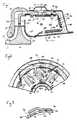
- Fig. 1 is a somewhat schematic, fragmentary, sectional view of a turbine made according to the invention;
- Fig. 2 is a fragmentary sectional view taken approximately along the line 2-2 in Fig. 1; and
- Fig. 3 is a fragmentary, enlarged sectional view of a cooling strip that may be utilized in the invention.
- An exemplary embodiment of a gas turbine made according to the invention is illustrated in the drawings in the form of a radial flow gas turbine. However, the invention is not so limited, having applicability to any form of turbine or other fuel combusting device requiring an annular combustor.
- The turbine includes a
rotary shaft 10 journalled by bearings not shown. Adjacent one end of theshaft 10 is aninlet area 12. Theshaft 10 mounts a rotor, generally designated 14 which may be of conventional construction. Accordingly, the same includes a plurality of compressor blades 16 adjacent theinlet 12. Acompressor blade shroud 18 is provided in adjacency thereto and just radially outwardly of the radially outer extremities of thecompressor blades 18 is aconventional diffuser 20. - Oppositely of the compressor blades 16, the
rotor 14 has a plurality ofturbine blades 22. Just radially outwardly of theturbine blades 22 is anannular nozzle 24 which is adapted to receive hot gasses of combustion from a combustor, generally designated 26. The compressor system including the blades 16,shroud 18 anddiffuser 20 delivers hot air to the combustor 26, and viadilution air passages nozzle 24 along with the gasses of combustion. That is to say, hot gasses of combustion from the combustor 26, are directed via thenozzle 24 against theblades 22 to cause rotation of therotor 14 and thus theshaft 10. The latter may be, of course, coupled to some sort of apparatus requiring the performance of useful work. - A turbine blade shroud 29 is interfitted with the combustor 26 to close off the flow path from the
nozzle 24 and confine the expanding gas to the area of theturbine blades 22. - The combustor 26 has a generally cylindrical
inner wall 32 and a generally cylindricalouter wall 34. The two are concentric and merge to a necked downarea 36 which serves as an outlet from theinterior annulus 38 of the combustor to thenozzle 24. Athird wall 39, generally radially extending and concentric with thewalls annulus 38 - Oppositely of the
outlet 36, and adjacent thewall 39, theinterior annulus 38 of the combustor 26 includes aprimary combustion zone 40. By primary combustion zone, it is meant that this is the area in which the burning of fuel primarily occurs. Other combustion may, in some instances, occur downstream from theprimary combustion area 40 in the direction of theoutlet 36. As mentioned earlier, provision is made for the injection of dilution air through thepassageways primary combustion zone 40 to cool the gasses of combustion to a temperature suitable for application to theturbine blades 22 via thenozzle 24. It should be noted that thepassageways passageways 28. This, of course, requires the vast majority of dilution air to pass about the generally radiallyouter wall 34, thethird wall 39 and the radiallyinner wall 32 which in turn provides excellent convective cooling of these combustor walls and avoids the formation of hot spots on any of thewalls - In any event, it will be seen that the
primary combustion zone 40 is an annulus or annular space defined by the generally radiallyinner wall 32, the generally radiallyouter wall 34 and thewall 39. - A further wall 44 is generally concentric to the
walls diffuser 20 and thus serves to contain and direct compressed air from the compressor system to the combustor 26. - As best seen in Fig. 2, the combustor 26 is provided with a plurality of fuel injection nozzles 50. The fuel injection nozzles 50 have ends 52 disposed within the
primary combustion zone 40 and which are configured to be nominally tangential to theinner wall 32. The fuel injection nozzles 50 generally but not necessarily utilize the pressure drop of fuel across swirl generating orifices (not shown) to accomplish fuel atomization. Tubes 54 surround the nozzles 50. High velocity air from the compressor flows through the tubes 54 to enhance fuel atomization. Thus the tubes 54 serve as air injection tubes. When swirl generating orifices are not used as in the embodiment illustrated, high velocity air flowing through the tubes 54 is the means by which fuel exiting the nozzles 50 is atomized. - The fuel injecting nozzles 50 are equally angularly spaced about the
primary combustion annulus 40 and optionally disposed between each pair of adjacent nozzles 50 there may be a combustion supporting air jet 56. When used, the jets 56 are located in thewall 34 and establish fluid communication between the air delivery annulus defined by thewalls 34 and 44 and theprimary combustion annulus 40. These jets 56 may be somewhat colloquially termed "bender" jets as will appear. They are also oriented so that the combustion supporting air entering through them enters theprimary combustion annulus 40 in a direction nominally tangential to theinner wall 32. - Preferably the injectors 50 and jets 56 are coplanar or in relatively closely spaced planes remote from the
outlet area 36. Such plane or planes are transverse to the axis of theshaft 10. - When the intended use of the engine requires the delivery of large quantities of bleed air, the wall 44 is provided with a series of
outlet openings 58 which in turn are surrounded by ableed air scroll 60 secured to the outer surface of the wall 44. Thus, bleed air to be used for conventional purposes may be made available at an outlet (not shown) from thescroll 60. - To prevent the formation of undesirable hot spots on the
walls walls annulus 38. Further, the invention provides means whereby the cooling air film is injected into theannulus 38 in a generally tangential, as opposed to axial, direction. - Preferably, the injection is provided along each of the
walls - In the case of the radially
inner wall 32, the same is provided with a series ofapertures 70. Preferably, theapertures 70 are arranged in a series of equally angularly spaced, generally axially extending rows. Thus, the threeapertures 70 shown in Fig. 2 constitute one aperture in each of three such rows while theapertures 70 illustrated in Fig. 1 constitute the apertures in a single such row. - A similar series of equally angularly spaced, axially extending rows of
apertures 72 is likewise provided in thewall 34. - Similarly, in the case of the
wall 39, there are a series of generally radially extending rows ofapertures 74. As can be readily appreciated, theapertures wall 34, a radially extending annulus defined by thewall 39 and a wall 80 connected to the wall 44, and the connecting annulus defined by thewall 32 and a connecting wall 82. - The tangential and film-like streams of the cooling air entering the
annulus 38 through theopenings strips walls - As a consequence of this construction, the air flowing in the annuli about the combustor 26 will remove heat therefrom by external convective cooling of the
walls walls annulus 38 resulting from film-like air flow into theannulus 38 through theapertures walls - Thus, in the preferred embodiment, the entirety of the internal surface of all of the walls, 32, 34 and 39 is completely covered with a film of air. The ability to completely cool the internal walls of a combustor is difficult to accomplish, particularly as combustor size decreases. However, utilizing the novel technique of tangential injection of air as herein disclosed readily accomplishes the establishment of a complete wall covering film to provide improved wall cooling. The film further serves to minimize carbon build-up and the elimination of hot spots on the combustor walls.
- These advantages are enhanced by reason of the jets of air which result from air flow through the
apertures walls - The cooling strips 86, 88 and 90 are generally similar one to the other and accordingly, it is believed that a complete understanding of the operation of the same can be achieved simply from understanding the operation of one. Thus, only the
cooling strip 86 will be described. - With reference to Fig. 3, the cooling
strip 86 is seen to be in the shape of a generally flattened "S" having anupstream edge 92 bonded to thewall 32 just upstream of a corresponding row of theopenings 70 by any suitable means as brazing or, for example, a weld 94. Because of the S shape of thecooling strip 86, this results in the opposite ordownstream edge 96 being elevated above theopening 70 with anexit opening 98 being present. Theexit opening 98 is elongated in the axial direction along with theedge 96 and also opens generally tangentially to thewall 32. Consequently, air entering theannulus 38 through the openings in the direction of arrows 100 (Figs. 2 and 3) will flow in a film-like fashion in a generally tangential direction along thewall 32 on its interior surface to cool the same. The air flow indicated by arrows 102 in Fig. 2 illustrate the corresponding tangential, film-like flow of cooling air on the interior of thewall 34 while additional arrows 104 in Fig. 2 illustrated a similar, tangential film-like air flow of air entering theopenings 74 in thewall 36. - Operation is generally as follows. Fuel emanating from each of the nozzles 50 will enter along a line such as shown at "F". This line will of course be straight and it will be expected that the fuel will diverge from it somewhat. Assuming bender jets 56 are used, as the fuel approaches the adjacent bender jet 56 in the clockwise direction, the incoming air from the
diffuser 20 and compressor blades 16 will tend to deflect or bend the fuel stream to a location more centrally of theprimary combustion annulus 40. There will, of course, be a substantial generation of turbulence at this time and such turbulence will promote uniformity of burn within theprimary combustion annulus 40 and this in turn will result in a uniform circumferential turbine inlet temperature distribution at thenozzle 24 and at radially outer ends of theturbine blades 22. Such uniform turbine inlet temperature distribution is achieved in a combustor made according to the invention utilizing many fewer fuel injecting nozzles 50 than would be required according to prior art teachings. As a result of the invention, and even without the use of the bender jets 56, through the use of tangential fuel injection and cooling film introduction, a combustor made according to the invention will require about half the number of fuel injector nozzles 50 as would a conventional combustor of equal volume. In particular, the two will have approximately the same so-called "pattern factor". - If the bender jets 56 are added without adding nozzles 50, an improvement in pattern factor will be obtained over the conventional combustor.
- In any event, resulting elimination of a number of fuel injector nozzles 50 provides a substantial cost savings. Moreover, in engines having an increased combustor volume, a further substantial reduction in the number of fuel injectors by as much as 80% of those required according to conventional practice may be obtained.
- It will also be observed that where the number of fuel injections nozzles 50 is halved using the principals of the invention, the fuel flow passages of the remaining fuel injection nozzles, assuming they are cylindrical, can be increased in diameter slightly over 40%. This increase in diameter reduces the possibility of plugging of the fuel injectors nozzles 50 to provide a more trouble free apparatus. This characteristic of the invention assumes extreme importance in small engines which utilize small combustors and thus have relatively small fuel flows, particularly at low engine speeds or while starting at high altitudes.
- In addition, the injection of cooling air in a filmlike manner achieved by means of the
openings annulus 38 does not provide an axial impetus to fuel droplets entering theprimary combustion zone 40 from the nozzles 50. As a consequence, there is ample time for such fuel to fully and completely vaporize within theprimary combustion zone 40 and thereby achieve highly efficient combustion. For example, in one combustor made according to the invention tested at 10% of rated engine speed with a combustor pressure drop of only 0.8 inches of water, a short efficient flame was obtained using No. 2 diesel fuel. In contrast, a conventional annular combustor using conventional swirl air blast injectors would typically be unable to sustain combustion under similar circumstances. Thus, an engine employing the invention is more easily started, a feature that may be particularly critical when high altitude operation is used as, for example, when the engine is used as part of an auxiliary power unit or an emergency power unit. Because a high degree of tangential motion or swirl is found desirable in a turbine made accordingly to the invention, deswirl vanes such as those somewhat schematically illustrated at 106 in Fig. 1 may be relatively minimal, thereby reducing the complexity of the invention. The swirl that is thus permitted conserves the angular velocity of the compressed air as it leaves thediffuser 20 so that the pressure drop is minimized, thereby enhancing operational efficiency. Furthermore, since theturbine nozzle 24 is designed to impart swirl to the hot gases directed against theturbine blades 22, the fact that the gases are already swirling as a result of tangential air and fuel injection minimizes the directional change applied to such gases by thenozzle 24 to provide a further increase in efficiency. - At the same time, the use of minimal
deswirl vanes 106 allows the initial swirl that is typically imparted to the compressed air by the compressor 16 anddiffuser 20 to be retained outside the combustor 26 allowing bleed air, which is commonly obtained from a circumferential vent enclosed by a scroll, to be obtained with a high degree of efficiency. According to the invention, the combustor is sized by an equation of the form:
Where
K is a constant;
Wa is the combustor air flow in pounds per second;
T₃ is the turbine inlet temperature in degrees Rankine;
T₂ is the combustor inlet temperature in degrees Rankine;
ΔP/P is the combustorpressure drop X 100;
P is the combustor air inlet pressure in psia;
ΔP is the combustor pressure drop in psia;
D is the mean combustor height in inches;
H is the mean combustor width in inches;
N is the number of fuel injectors; and
R is the engine pressure ratio. - The present invention provides a trade-off between combustor volume and the number of injectors. It is a trade-off that cannot be achieved in conventional combustors. Specifically, in a conventional combustor, the number of injectors is determined generally by the expression N=π D/H.
- If the number of injectors as defined by the preceding equation is reduced, there is a serious increase in turbine inlet hot spots. In one combustor made according to the invention, only four injectors were required whereas normal practice would require about thirteen such injectors. Further, in the combustor made according to the invention, a pattern factor of 0.095 was obtained. The pattern factor is a measure of the uniformity of temperature throughout the combustion area and is defined by the formula

where Th is a temperature of the hottest spot in degrees Rankine. - In any event, the pattern factor of 0.095 obtained in a combustor made according to the invention is twice as good as the pattern factor that would be obtained in normal practice with thirteen injectors.
- Further, when one of the fuel injectors in the four injector structure made according to the invention was plugged up to simulate a typical field failure, the pattern factor increased only to 0.11, a negligible increase. Conversely, extensive experience in turbine engines has indicated that if one injector plugs up in a conventional combustor, the resulting hot spot will seriously damage or even destroy the turbine engine.
- Similarly, when a combustor employing two diametrically opposite injectors with two intermediate bender jets was employed, a pattern factor of 0.2 was obtained. This pattern factor is comparable to that which would be obtained in a conventional combustor utilizing 13 injectors. The improvements in pattern factors along with the ability to tolerate plugging as well as the elimination of a large number of injectors clearly the demonstrates the superiority of the invention.
- In addition, in a combustor made according to the invention, a test was run with fuel flowing only out of one injector of the four provided. The injector from which fuel was flowing was the lowermost one and the test was to simulate start-up of the engine at very high altitudes when, due to so-called "manifold head" effects, at low fuel flow rates, substantially all fuel flows into the combustor through the lowermost injector. The resulting flame visually observed spread about the entire combustor and the pattern factor was a tolerable 0.33. Conversely, in a conventional combustor wherein fuel is flowed only through one injector, a very localized flame with inefficient burning is observed and starting at altitudes is poor.
- Thus, in addition to the previously stated advantages, the invention is ideally suited for use in turbine engines, particularly small turbine engines, that may be operated at high altitudes and require starting at such altitudes as well.


Claims (10)
- A gas turbine comprising:
a rotor (14) including compressor blades (16) and turbine blades (22);
an inlet (12) adjacent one side of the compressor blades;
a diffuser (20) adjacent the other side of the compressor blades;
a nozzle(24) adjacent the turbine blades for directing hot gases at the turbine blades to cause rotation of the rotor; and
an annular combustor (26) having radially inner and outer walls (32,34) connected by a generally radially extending wall (39) about the rotor and having an outlet (36) connected to the nozzle and a primary combustion annulus (40) defined by the wall remote from the outlet;
CHARACTERIZED BY further comprising:
means (70,86; 72,88; 74,90) associated with each of the inner, outer and radial walls (32,34,39) of the primary combustion annulus (40) for injecting a film-like stream of cooling air in a generally tangential direction along each wall. - A gas turbine according to claim 1, wherein the film-like stream of cooling air covers substantially the whole of the walls (32,34,39) of the primary combustion annulus (40).
- A gas turbine according to claim 1 or claim 2, wherein the cooling air injection means (70,86; 72,88; 74,90) include cooling air openings (70,72,74) in fluid communication with the diffuser (20) to receive compressed gas therefrom.
- A gas turbine according to claim 3, wherein a compressed gas housing (80) surrounds the combustor (26), in spaced relation thereto and is in fluid communication with the diffuser (20), the cooling air openings (70,72,74) extending to a space between the housing (80) and combustor (26) to receive compressed gas therefrom.
- A gas turbine according to claim 3 or claim 4, wherein each of the cooling air film injectors (70,86; 72,88; 74,90) further includes a cooling strip (86,88,90) having an edge (96) overlying and spaced from the row of openings (70,72,74).
- A gas turbine according to claim 5, wherein the cooling strips (86,88,90) each have a cross section in the shape of a flattened "S".
- A gas turbine according to claim 5 or claim 6, wherein the rows of openings (70,72,74) and strips (86,88,90) associated with the inner and outer walls (32,34) extend generally axially.
- A gas turbine according to any of claims 5 to 7, wherein the rows of openings (70,72,74) and the strips (86,88,90) associated with the radial wall (39) extend generally radially.
- A gas turbine according to any preceding claim, further comprising a plurality of fuel injectors (50) to the primary combustion annulus (40) and being substantially equally angularly spaced therearound and configured to inject fuel into the primary combustion annulus in a generally tangential direction.
- A gas turbine according to claim 9, wherein the fuel injectors comprise fuel nozzles having ends (52) within the primary combustion annulus (40) of the annulus combustor (26), and atomizing nozzles for the combustion supporting gas surrounding the ends.
Applications Claiming Priority (2)
| Application Number | Priority Date | Filing Date | Title |
|---|---|---|---|
| US07/138,342US4928479A (en) | 1987-12-28 | 1987-12-28 | Annular combustor with tangential cooling air injection |
| US138342 | 1987-12-28 |
Publications (3)
| Publication Number | Publication Date |
|---|---|
| EP0348500A1 EP0348500A1 (en) | 1990-01-03 |
| EP0348500A4 EP0348500A4 (en) | 1990-04-10 |
| EP0348500B1true EP0348500B1 (en) | 1993-03-03 |
Family
ID=22481605
Family Applications (1)
| Application Number | Title | Priority Date | Filing Date |
|---|---|---|---|
| EP89902491AExpired - LifetimeEP0348500B1 (en) | 1987-12-28 | 1988-12-21 | Annular combustor with tangential cooling air injection |
Country Status (5)
| Country | Link |
|---|---|
| US (2) | US4928479A (en) |
| EP (1) | EP0348500B1 (en) |
| JP (1) | JPH02503110A (en) |
| DE (1) | DE3878902T2 (en) |
| WO (1) | WO1989006308A1 (en) |
Families Citing this family (59)
| Publication number | Priority date | Publication date | Assignee | Title |
|---|---|---|---|---|
| US5109671A (en)* | 1989-12-05 | 1992-05-05 | Allied-Signal Inc. | Combustion apparatus and method for a turbine engine |
| US5263316A (en)* | 1989-12-21 | 1993-11-23 | Sundstrand Corporation | Turbine engine with airblast injection |
| US5277021A (en)* | 1991-05-13 | 1994-01-11 | Sundstrand Corporation | Very high altitude turbine combustor |
| US5265425A (en)* | 1991-09-23 | 1993-11-30 | General Electric Company | Aero-slinger combustor |
| US5237813A (en)* | 1992-08-21 | 1993-08-24 | Allied-Signal Inc. | Annular combustor with outer transition liner cooling |
| US5317864A (en)* | 1992-09-30 | 1994-06-07 | Sundstrand Corporation | Tangentially directed air assisted fuel injection and small annular combustors for turbines |
| US5479781A (en)* | 1993-09-02 | 1996-01-02 | General Electric Company | Low emission combustor having tangential lean direct injection |
| US5488829A (en)* | 1994-05-25 | 1996-02-06 | Westinghouse Electric Corporation | Method and apparatus for reducing noise generated by combustion |
| US5746048A (en)* | 1994-09-16 | 1998-05-05 | Sundstrand Corporation | Combustor for a gas turbine engine |
| US5628193A (en)* | 1994-09-16 | 1997-05-13 | Alliedsignal Inc. | Combustor-to-turbine transition assembly |
| DE4446945B4 (en)* | 1994-12-28 | 2005-03-17 | Alstom | Gas powered premix burner |
| US5727378A (en)* | 1995-08-25 | 1998-03-17 | Great Lakes Helicopters Inc. | Gas turbine engine |
| US5680765A (en)* | 1996-01-05 | 1997-10-28 | Choi; Kyung J. | Lean direct wall fuel injection method and devices |
| KR20000069290A (en)* | 1996-12-03 | 2000-11-25 | 번함.더글라스 알. | Electrical system for turbine/alternator on common shaft |
| EP0943069B1 (en) | 1996-12-03 | 2003-10-08 | Elliott Energy Systems, Inc. | An electricity generating system having an annular combustor |
| DE59710046D1 (en)* | 1997-03-20 | 2003-06-12 | Alstom Switzerland Ltd | Gas turbine with a toroidal combustion chamber |
| US5850732A (en)* | 1997-05-13 | 1998-12-22 | Capstone Turbine Corporation | Low emissions combustion system for a gas turbine engine |
| US5966926A (en) | 1997-05-28 | 1999-10-19 | Capstone Turbine Corporation | Liquid fuel injector purge system |
| US6453658B1 (en) | 2000-02-24 | 2002-09-24 | Capstone Turbine Corporation | Multi-stage multi-plane combustion system for a gas turbine engine |
| BR0109283A (en) | 2000-03-14 | 2002-12-17 | James Hardie Res Pty Ltd | Fiber cement construction materials containing low density additives |
| CA2407717A1 (en) | 2000-05-01 | 2001-11-08 | J. Michael Teets | Annular combustor for use with an energy system |
| US6928823B2 (en)* | 2001-08-29 | 2005-08-16 | Hitachi, Ltd. | Gas turbine combustor and operating method thereof |
| US6813889B2 (en)* | 2001-08-29 | 2004-11-09 | Hitachi, Ltd. | Gas turbine combustor and operating method thereof |
| US6675587B2 (en)* | 2002-03-21 | 2004-01-13 | United Technologies Corporation | Counter swirl annular combustor |
| US6955053B1 (en)* | 2002-07-01 | 2005-10-18 | Hamilton Sundstrand Corporation | Pyrospin combuster |
| CN1684760A (en)* | 2002-08-23 | 2005-10-19 | 詹姆士·哈代国际金融公司 | Synthetic hollow microspheres |
| MXPA05003691A (en) | 2002-10-07 | 2005-11-17 | James Hardie Int Finance Bv | Durable medium-density fibre cement composite. |
| US20090146108A1 (en)* | 2003-08-25 | 2009-06-11 | Amlan Datta | Methods and Formulations for Producing Low Density Products |
| US20090156385A1 (en)* | 2003-10-29 | 2009-06-18 | Giang Biscan | Manufacture and use of engineered carbide and nitride composites |
| JP4317214B2 (en)* | 2004-03-09 | 2009-08-19 | 株式会社日立製作所 | Radial turbine and method for cooling nozzle thereof |
| US7998571B2 (en) | 2004-07-09 | 2011-08-16 | James Hardie Technology Limited | Composite cement article incorporating a powder coating and methods of making same |
| CA2598708A1 (en)* | 2005-02-24 | 2006-08-31 | James Hardie International Finance B.V. | Alkali resistant glass compositions |
| WO2006112971A2 (en)* | 2005-04-13 | 2006-10-26 | Corning Incorporated | Mode-matching system for tunable external cavity laser |
| CA2632760C (en)* | 2005-12-08 | 2017-11-28 | James Hardie International Finance B.V. | Engineered low-density heterogeneous microparticles and methods and formulations for producing the microparticles |
| US8993462B2 (en) | 2006-04-12 | 2015-03-31 | James Hardie Technology Limited | Surface sealed reinforced building element |
| US20070275335A1 (en)* | 2006-05-25 | 2007-11-29 | Giang Biscan | Furnace for heating particles |
| US8701416B2 (en)* | 2006-06-26 | 2014-04-22 | Joseph Michael Teets | Radially staged RQL combustor with tangential fuel-air premixers |
| US7942006B2 (en)* | 2007-03-26 | 2011-05-17 | Honeywell International Inc. | Combustors and combustion systems for gas turbine engines |
| US7798765B2 (en)* | 2007-04-12 | 2010-09-21 | United Technologies Corporation | Out-flow margin protection for a gas turbine engine |
| JP4304541B2 (en)* | 2007-06-27 | 2009-07-29 | トヨタ自動車株式会社 | Extraction type gas turbine |
| US7921653B2 (en)* | 2007-11-26 | 2011-04-12 | General Electric Company | Internal manifold air extraction system for IGCC combustor and method |
| US20090199563A1 (en)* | 2008-02-07 | 2009-08-13 | Hamilton Sundstrand Corporation | Scalable pyrospin combustor |
| WO2010051338A1 (en)* | 2008-10-30 | 2010-05-06 | Power Generation Technologies Development Fund L.P. | Toroidal boundary layer gas turbine |
| US9052116B2 (en) | 2008-10-30 | 2015-06-09 | Power Generation Technologies Development Fund, L.P. | Toroidal heat exchanger |
| US9181812B1 (en)* | 2009-05-05 | 2015-11-10 | Majed Toqan | Can-annular combustor with premixed tangential fuel-air nozzles for use on gas turbine engines |
| US9062609B2 (en)* | 2012-01-09 | 2015-06-23 | Hamilton Sundstrand Corporation | Symmetric fuel injection for turbine combustor |
| US9494081B2 (en) | 2013-05-09 | 2016-11-15 | Siemens Aktiengesellschaft | Turbine engine shutdown temperature control system with an elongated ejector |
| US9404422B2 (en)* | 2013-05-23 | 2016-08-02 | Honeywell International Inc. | Gas turbine fuel injector having flow guide for receiving air flow |
| US10072846B2 (en)* | 2015-07-06 | 2018-09-11 | General Electric Company | Trapped vortex cavity staging in a combustor |
| US20170159565A1 (en)* | 2015-12-04 | 2017-06-08 | Jetoptera, Inc. | Micro-turbine gas generator and propulsive system |
| US9803552B2 (en)* | 2015-10-30 | 2017-10-31 | General Electric Company | Turbine engine fuel injection system and methods of assembling the same |
| US9810434B2 (en)* | 2016-01-21 | 2017-11-07 | Siemens Energy, Inc. | Transition duct system with arcuate ceramic liner for delivering hot-temperature gases in a combustion turbine engine |
| US11635030B2 (en) | 2017-06-13 | 2023-04-25 | General Electric Company | Compressor bleed apparatus for a turbine engine |
| RU182644U1 (en)* | 2018-03-28 | 2018-08-24 | Федеральное государственное унитарное предприятие "Центральный институт авиационного моторостроения им. П.И. Баранова" | The annular combustion chamber of a small gas turbine engine |
| US11378277B2 (en) | 2018-04-06 | 2022-07-05 | General Electric Company | Gas turbine engine and combustor having air inlets and pilot burner |
| CN111706878A (en)* | 2020-06-01 | 2020-09-25 | 滁州帝邦科技有限公司 | Double oil-way opposite-impact direct-injection type nozzle |
| US12241419B2 (en) | 2022-08-25 | 2025-03-04 | Collins Engine Nozzles, Inc. | Fuel injectors assemblies with tangential flow component |
| US20250109853A1 (en)* | 2023-09-28 | 2025-04-03 | General Electric Company | Combustion section with a primary combustor and a set of secondary combustors |
| US12215604B1 (en)* | 2023-12-22 | 2025-02-04 | Rtx Corporation | Cooling nozzle vanes of a turbine engine |
Family Cites Families (26)
| Publication number | Priority date | Publication date | Assignee | Title |
|---|---|---|---|---|
| US2638745A (en)* | 1943-04-01 | 1953-05-19 | Power Jets Res & Dev Ltd | Gas turbine combustor having tangential air inlets for primary and secondary air |
| BE486092A (en)* | 1947-12-04 | |||
| GB762596A (en)* | 1954-02-18 | 1956-11-28 | Armstrong Siddeley Motors Ltd | A combustion chamber, particularly for a gas turbine engine |
| US3064425A (en)* | 1959-10-05 | 1962-11-20 | Gen Motors Corp | Combustion liner |
| US3099134A (en)* | 1959-12-24 | 1963-07-30 | Havilland Engine Co Ltd | Combustion chambers |
| US3169369A (en)* | 1963-06-19 | 1965-02-16 | Gen Electric | Combustion system |
| GB1060095A (en)* | 1964-05-13 | 1967-02-22 | Rolls Royce | Improvements relating to the flow of a cooling fluid |
| CH428324A (en)* | 1964-05-21 | 1967-01-15 | Prvni Brnenska Strojirna | Combustion chamber |
| FR1430185A (en)* | 1964-12-23 | 1966-03-04 | Swirl slot combustion hearth | |
| GB1099374A (en)* | 1965-03-23 | 1968-01-17 | Prvni Brnenska Strojirna Zd Y | Improvements in or relating to cooled walls of gas-turbine combustion chambers |
| US3422620A (en)* | 1967-05-04 | 1969-01-21 | Westinghouse Electric Corp | Combustion apparatus |
| US3520134A (en)* | 1969-02-26 | 1970-07-14 | United Aircraft Corp | Sectional annular combustion chamber |
| US3613360A (en)* | 1969-10-30 | 1971-10-19 | Garrett Corp | Combustion chamber construction |
| US3811277A (en)* | 1970-10-26 | 1974-05-21 | United Aircraft Corp | Annular combustion chamber for dissimilar fluids in swirling flow relationship |
| US3788065A (en)* | 1970-10-26 | 1974-01-29 | United Aircraft Corp | Annular combustion chamber for dissimilar fluids in swirling flow relationship |
| US3691766A (en)* | 1970-12-16 | 1972-09-19 | Rolls Royce | Combustion chambers |
| GB1424197A (en)* | 1972-06-09 | 1976-02-11 | Lucas Industries Ltd | Combustion chambers for gas turbine engines |
| US3793827A (en)* | 1972-11-02 | 1974-02-26 | Gen Electric | Stiffener for combustor liner |
| US4006589A (en)* | 1975-04-14 | 1977-02-08 | Phillips Petroleum Company | Low emission combustor with fuel flow controlled primary air flow and circumferentially directed secondary air flows |
| GB1600130A (en)* | 1977-05-21 | 1981-10-14 | Rolls Royce | Combustion systems |
| DE3061595D1 (en)* | 1979-05-18 | 1983-02-17 | Rolls Royce | Combustion apparatus for gas turbine engines |
| JPS56124834A (en)* | 1980-03-05 | 1981-09-30 | Hitachi Ltd | Gas-turbine combustor |
| US4361010A (en)* | 1980-04-02 | 1982-11-30 | United Technologies Corporation | Combustor liner construction |
| US4302941A (en)* | 1980-04-02 | 1981-12-01 | United Technologies Corporation | Combuster liner construction for gas turbine engine |
| US4404806A (en)* | 1981-09-04 | 1983-09-20 | General Motors Corporation | Gas turbine prechamber and fuel manifold structure |
| EP0111874B1 (en)* | 1982-12-15 | 1987-04-22 | Gewerkschaft Sophia-Jacoba Steinkohlenbergwerk | A device for burning coal dust |
- 1987
- 1987-12-28USUS07/138,342patent/US4928479A/ennot_activeCeased
- 1988
- 1988-12-21EPEP89902491Apatent/EP0348500B1/ennot_activeExpired - Lifetime
- 1988-12-21DEDE8989902491Tpatent/DE3878902T2/ennot_activeExpired - Fee Related
- 1988-12-21JPJP89502372Apatent/JPH02503110A/enactivePending
- 1988-12-21WOPCT/US1988/004582patent/WO1989006308A1/enactiveIP Right Grant
- 1992
- 1992-05-29USUS07/890,916patent/USRE34962E/ennot_activeExpired - Lifetime
Also Published As
| Publication number | Publication date |
|---|---|
| DE3878902T2 (en) | 1993-06-17 |
| WO1989006308A1 (en) | 1989-07-13 |
| US4928479A (en) | 1990-05-29 |
| DE3878902D1 (en) | 1993-04-08 |
| EP0348500A1 (en) | 1990-01-03 |
| JPH02503110A (en) | 1990-09-27 |
| USRE34962E (en) | 1995-06-13 |
| EP0348500A4 (en) | 1990-04-10 |
Similar Documents
| Publication | Publication Date | Title |
|---|---|---|
| EP0348500B1 (en) | Annular combustor with tangential cooling air injection | |
| US4891936A (en) | Turbine combustor with tangential fuel injection and bender jets | |
| US4949545A (en) | Turbine wheel and nozzle cooling | |
| US5540056A (en) | Cyclonic prechamber with a centerbody for a gas turbine engine combustor | |
| US4977740A (en) | Dual fuel injector | |
| US6178751B1 (en) | Liquid fuel injector system | |
| US5406799A (en) | Combustion chamber | |
| JP2654425B2 (en) | Annular combustor | |
| EP1847778A1 (en) | Pre-mix combustion system for a gas turbine and method of operating the same | |
| US4989404A (en) | Turbine engine with high efficiency fuel atomization | |
| US7062919B2 (en) | Vortex fuel nozzle to reduce noise levels and improve mixing | |
| US4944152A (en) | Augmented turbine combustor cooling | |
| US5027603A (en) | Turbine engine with start injector | |
| US4974415A (en) | Staged, coaxial multiple point fuel injection in a hot gas generator | |
| US5241818A (en) | Fuel injector for a gas turbine engine | |
| US4967563A (en) | Turbine engine with high efficiency fuel atomization | |
| US5150570A (en) | Unitized fuel manifold and injector for a turbine engine | |
| US4967562A (en) | Turbine engine with high efficiency fuel atomization | |
| US4938020A (en) | Low cost annular combustor | |
| JP4117931B2 (en) | Turbocooler air-assisted fuel spraying in gas turbine engines | |
| US5140807A (en) | Air blast tube impingement fuel injector for a gas turbine engine | |
| EP0687350B1 (en) | Dual fuel injection nozzle with water injection | |
| JP3986685B2 (en) | Combustor for gas turbine engine | |
| JP2000074373A (en) | Gas turbine engine combustor | |
| EP0059855A1 (en) | Catalytic combustor having secondary fuel injection for low NOx stationary combustion turbines |
Legal Events
| Date | Code | Title | Description |
|---|---|---|---|
| PUAI | Public reference made under article 153(3) epc to a published international application that has entered the european phase | Free format text:ORIGINAL CODE: 0009012 | |
| 17P | Request for examination filed | Effective date:19890919 | |
| AK | Designated contracting states | Kind code of ref document:A1 Designated state(s):DE FR GB | |
| A4 | Supplementary search report drawn up and despatched | Effective date:19900410 | |
| 17Q | First examination report despatched | Effective date:19910626 | |
| GRAA | (expected) grant | Free format text:ORIGINAL CODE: 0009210 | |
| AK | Designated contracting states | Kind code of ref document:B1 Designated state(s):DE FR GB | |
| REF | Corresponds to: | Ref document number:3878902 Country of ref document:DE Date of ref document:19930408 | |
| ET | Fr: translation filed | ||
| PLBE | No opposition filed within time limit | Free format text:ORIGINAL CODE: 0009261 | |
| STAA | Information on the status of an ep patent application or granted ep patent | Free format text:STATUS: NO OPPOSITION FILED WITHIN TIME LIMIT | |
| 26N | No opposition filed | ||
| PGFP | Annual fee paid to national office [announced via postgrant information from national office to epo] | Ref country code:DE Payment date:19991202 Year of fee payment:12 | |
| PGFP | Annual fee paid to national office [announced via postgrant information from national office to epo] | Ref country code:GB Payment date:19991203 Year of fee payment:12 Ref country code:FR Payment date:19991203 Year of fee payment:12 | |
| PG25 | Lapsed in a contracting state [announced via postgrant information from national office to epo] | Ref country code:GB Free format text:LAPSE BECAUSE OF NON-PAYMENT OF DUE FEES Effective date:20001221 | |
| GBPC | Gb: european patent ceased through non-payment of renewal fee | Effective date:20001221 | |
| PG25 | Lapsed in a contracting state [announced via postgrant information from national office to epo] | Ref country code:FR Free format text:LAPSE BECAUSE OF NON-PAYMENT OF DUE FEES Effective date:20010831 | |
| REG | Reference to a national code | Ref country code:FR Ref legal event code:ST | |
| PG25 | Lapsed in a contracting state [announced via postgrant information from national office to epo] | Ref country code:DE Free format text:LAPSE BECAUSE OF NON-PAYMENT OF DUE FEES Effective date:20011002 |