EP0348294B1 - Safety arrangement for preventing the mixing of products transferred between a fixed storage tank and a mobile reservoir - Google Patents
Safety arrangement for preventing the mixing of products transferred between a fixed storage tank and a mobile reservoirDownload PDFInfo
- Publication number
- EP0348294B1 EP0348294B1EP89401733AEP89401733AEP0348294B1EP 0348294 B1EP0348294 B1EP 0348294B1EP 89401733 AEP89401733 AEP 89401733AEP 89401733 AEP89401733 AEP 89401733AEP 0348294 B1EP0348294 B1EP 0348294B1
- Authority
- EP
- European Patent Office
- Prior art keywords
- key
- valve
- unlocking device
- unlocking
- tanker
- Prior art date
- Legal status (The legal status is an assumption and is not a legal conclusion. Google has not performed a legal analysis and makes no representation as to the accuracy of the status listed.)
- Expired - Lifetime
Links
- 238000009434installationMethods0.000claimsdescription14
- 239000012530fluidSubstances0.000claimsdescription11
- 230000000295complement effectEffects0.000claimsdescription3
- 238000007599dischargingMethods0.000claims1
- 239000000203mixtureSubstances0.000description4
- 238000012384transportation and deliveryMethods0.000description4
- 238000004891communicationMethods0.000description3
- 239000000446fuelSubstances0.000description3
- 230000000903blocking effectEffects0.000description2
- 238000002955isolationMethods0.000description2
- 239000004215Carbon black (E152)Substances0.000description1
- 238000004140cleaningMethods0.000description1
- 239000003086colorantSubstances0.000description1
- 230000000694effectsEffects0.000description1
- 229930195733hydrocarbonNatural products0.000description1
- 150000002430hydrocarbonsChemical class0.000description1
- 238000003780insertionMethods0.000description1
- 230000037431insertionEffects0.000description1
- 238000012795verificationMethods0.000description1
- 238000004804windingMethods0.000description1
Images


Classifications
- B—PERFORMING OPERATIONS; TRANSPORTING
- B67—OPENING, CLOSING OR CLEANING BOTTLES, JARS OR SIMILAR CONTAINERS; LIQUID HANDLING
- B67D—DISPENSING, DELIVERING OR TRANSFERRING LIQUIDS, NOT OTHERWISE PROVIDED FOR
- B67D7/00—Apparatus or devices for transferring liquids from bulk storage containers or reservoirs into vehicles or into portable containers, e.g. for retail sale purposes
- B67D7/06—Details or accessories
- B67D7/32—Arrangements of safety or warning devices; Means for preventing unauthorised delivery of liquid
- B67D7/34—Means for preventing unauthorised delivery of liquid
- B67D7/344—Means for preventing unauthorised delivery of liquid by checking a correct coupling or coded information
- E—FIXED CONSTRUCTIONS
- E05—LOCKS; KEYS; WINDOW OR DOOR FITTINGS; SAFES
- E05B—LOCKS; ACCESSORIES THEREFOR; HANDCUFFS
- E05B51/00—Operating or controlling locks or other fastening devices by other non-mechanical means
- E05B51/02—Operating or controlling locks or other fastening devices by other non-mechanical means by pneumatic or hydraulic means
Definitions
- the inventionrelates to a safety installation intended to avoid mixing of products during unloading operations between at least one fixed tank and at least one mobile tank.
- the verification and control instructionscan be increased, and the number of tanks or tanker truck compartments reduced if necessary.
- this obviouslydoes not give satisfaction and it is on the contrary necessary to increase the possibilities of delivery with the arrival of new types of fuels, which can only increase the risks of mixtures.
- the inventionrelates more particularly to fuel delivery installations, as will be specified below, but the invention is of course generalized to the unloading of other products.
- the locking systemscan be arranged to be unlocked by any means, electric or other.
- a preferred embodimentis remarkable in that said valve locking systems are arranged to be unlocked by the action of a fluid, in that the connecting means is a flexible pipe, in that the device for unlocking is connected to a fluid supply circuit and in that the key is arranged to allow the fluid of said supply circuit to actuate the unlocking of the locking systems when the key corresponds to the recognition means of the unlocking device, which recognition means is arranged to receive and retain said key.
- the keyis tubular and has at least one passage at its end
- the unlocking devicecomprises a double-passage valve, intended to put the fluid supply circuit in communication, on the one hand, with inside the key and therefore with the locking system of one of the valves, via the flexible pipe and, on the other hand, with the locking system of the other valve which is provided with said unlocking device, via a control pipe.
- the valvecomprises a part which is slidably mounted and which is provided with at least one opening intended to put the supply circuit into communication with the passage of the key, through said opening in the room.
- a valve urged to close by another elastic meansmakes it possible to connect the circuit d 'supply with the control line when it is biased against said other elastic means by at least part of the sliding part.
- the means for recognizing the locking deviceis, for example, a receptacle provided with retaining means arranged in conjunction with means complementary to the key for retaining the latter when said complementary means cooperate with one another.
- the receptacle provided with the retaining meansis, for example, removably fixed so that it can be changed at will depending on the product contained in the tank or respectively the tank, the valve of which is equipped with the unlocking device.
- said receptacleis a moving part provided with several sets of retaining means, so as to allow a set of means to be selected according to the position of said moving part, depending on the product contained in the tank or respectively the tank, the valve of which is fitted with the unlocking device.
- each keybeing coded according to the product to be received and each unlocking device being provided with a recognition means coded according to the product contained in the corresponding compartment.
- the unlocking control means of the locking systemsare actuated by a fluid
- thiscan be oil or a gas.
- the fluid in questionis air and that the supply circuit is the pneumatic service circuit of the truck.
- FIG. 1shows a tank truck 1 fitted with a battery of valves 2a to 2k.
- Each valve 2generally corresponds to a tank or a compartment of the tanker truck and makes it possible to transfer the product from said compartment to a fixed tank provided with a valve such as 3, by means of a stripping pipe 4.
- valve 2ais in operation and, as shown in the said figure, the valve 3 is connected via a flexible pipe 6, to a device 5a associated with said valve 2a and of which it will be discussed in more detail below.
- Line 6is arranged to be stored at rest in a support 7, for example by winding.
- FIG. 2shows one of the valves of the truck, referenced by the general number 2.
- This valve 2can be opened and closed by means of an operating handle 8.
- the handle 8can be blocked at the opening (which is done by a pulling action towards the front), by a single-acting cylinder, which constitutes a locking system 9 for said valve.
- the locking system 9 and more particularly the actuator which constitutes it,is connected, by a control pipe shown diagrammatically at 10, to an unlocking device of general reference 5 ( Figures 2, 3 and 4).
- the unlocking device 5is designed to receive the end of the flexible pipe 6 ( Figures 1 and 2).
- the device 5is arranged to receive a tubular part 12, shown in perspective in isolation in FIG. 5, while the end of the pipe 6 is equipped with a tubular key 13 shown in isolation in FIG. 6 and which is intended to be introduced into the tubular part 12 ( Figures 2, 7a and 7b).
- the device 5comprises a housing 14 (FIG. 4) for receiving a corresponding part 14 ′ of the part 12 (FIG. 5) while a blocking means 15 (FIGS. 3 and 4) is provided for blocking and unlocking the part 12 which is provided with conjugate means 15 ′ (FIG. 5), said means also being able to be of the bayonet type for example, or others.
- the part 12is provided with spring plungers referenced 16 and 17.
- the plunger 16is a split spring plunger and the plunger 17 is a hexagonal spring plunger.
- the pushers 16 and 17are intended to constitute retaining means for the key 13 ( Figures 7b and 7c), when the latter is provided with combined means in the form of a groove 18 ( Figures 6).
- the pushers 16 and 17constitute for the part 12, means for recognizing and retaining the key 13, when the latter is provided with combined means. It is therefore clear that the key can be coded at will according to the product to be received by the tank, the valve 3 of which is connected to line 6, while in the same way, the part 12 can be coded according to the product contained. in the compartment of the truck which corresponds to the valve 2 connected by 9 to the unlocking device provided with said part 12 ( Figure 2).
- the device 5 and more generally all the unlocking devices (5a to 5k; one per truck valve)are connected to the pneumatic service circuit of the truck by means of a main body 19 which is provided with a central bore in which circulates the air in the circuit according to arrow F1 ( Figures 7a, 7b, 7c).
- a part 20which is slidably mounted in leaktight manner thanks to O-rings 21.
- the part 20is provided with at least one opening such as 22, arranged so as to communicate with the central bore of the body 19 (FIGS. 7b and 7c) when the said part is sufficiently slid (to the right with respect to FIGS. 7a to 7c) against the stress of a spring 23.
- the part 20is provided with a lug 24 intended to come to urge a spherical valve 25.
- the valve 25is intended, when pushed by the lug 24, to communicate the central bore of the body 19 with an outlet 26 (Figure 7c), the latter being connected to the control line 10 ( Figure 2), while another spring 27 urges the valve 25 to close.
- the part 20is also provided with a stop ring 28, intended to come to the end of the race in abutment on the body 19.
- the key 13is provided at its end with a passage 29 (FIG. 6) and the valve 3 of the fixed tank (FIG. 1) is provided with an opening means such as a handwheel 11 locked by a means 30, which can be unlocked pneumatically. As shown in FIG. 1, the means 30 is connected to the pipe 6.
- Each valve 3is provided with a pipe 6 and a key 13, coded according to the product to be received.
- Each device 5(5a to 5k in FIG. 1) is provided with a part 12 coded according to the product of the corresponding compartment of the tank.
- valve 3is locked by system 30 and each valve 2 (2a to 2k) is blocked by its locking system 9.
- Figure 7ashows the device before the introduction of the key 13, the air of the truck service circuit passing through the body 13 according to arrow F1.
- Figure 7bshows the key 13 in the partial insertion position.
- the part 20 pushed by the end of the key 13puts the opening 22 of the part 20 into communication with the central bore of the body 19.
- the passage 29 of the key 13(FIG. 6) is arranged in so as to be positioned substantially coaxially with the aperture 22 of the part 20 when said key is fully inserted into the part 12, so that the air from the body 19 reaches the key 13, as shown by the arrow F2 of Figures 7b and 7c.
- the key 13must be pushed further to take the position of Figure 7c and open the valve 25 so as to send air through 26 according to arrow F3.
- pressurized airis sent, on the one hand, according to F2 to the system 30 of the valve 3 via the line 6, which allows pneumatic unlocking of the said system 30 and, on the other hand, according to F3 to the system 9 via the line 10 ( Figure 2), which allows unlocking of said system 9 and therefore, possible stripping between the truck and the fixed tank.
- compartments or tanks of the truckare intended to receive various products, it suffices each time the truck is filled, to provide the appropriate parts 12.
- valve side locking systems on the truck sidecould also, according to one embodiment, be a check of the bottom valves of the compartments considered, said valves being actuated by the unlocking devices.
Landscapes
- Engineering & Computer Science (AREA)
- Mechanical Engineering (AREA)
- Loading And Unloading Of Fuel Tanks Or Ships (AREA)
- Lock And Its Accessories (AREA)
- Air Transport Of Granular Materials (AREA)
- Emergency Alarm Devices (AREA)
Abstract
Description
Translated fromFrenchL'invention concerne une installation de sécurité destinée à éviter les mélanges de produits au cours d'opérations de dépotage entre au moins une cuve fixe et au moins une citerne mobile.The invention relates to a safety installation intended to avoid mixing of products during unloading operations between at least one fixed tank and at least one mobile tank.
Les mélanges malencontreux de produits, effectués au cours de livraisons, et plus particulièrement de livraisons de carburants entre les camions citerne et les cuves des stations service, sont très nombreux.Unfortunate mixtures of products, carried out during deliveries, and more particularly of fuel deliveries between tankers and tanks of service stations, are very numerous.
Les risques de mélanges sont énormes quand on sait que les stations service sont généralement pourvues de plusieurs cuves munies de vannes de remplissage d'apparence identique et que les camions citerne sont également pourvus de plusieurs vannes pour les vidanges, parfois de plusieurs compartiments distincts ou cuves.The risks of mixing are enormous when you know that service stations are generally provided with several tanks provided with identical filling valves and that tank trucks are also provided with several valves for emptying, sometimes with several separate compartments or tanks. .
Les risques de mélanges sont encore accrus, du fait que les affectations des cuves de réception, comme celles des cuves du camion, varient dans le temps de telle sorte qu'une cuve pour un produit devient une cuve pour un autre produit, alors qu'un mélange des deux produits entraîne souvent la perte totale des produits et nécessite un travail de nettoyage des cuves, important.The risks of mixing are further increased, because the assignments of the receiving tanks, like those of the truck tanks, vary over time so that a tank for one product becomes a tank for another product, while a mixture of the two products often results in the total loss of the products and requires significant tank cleaning work.
Les mélanges ainsi occasionnés causent dans tous les cas des frais souvent considérables.In any case, the resulting mixtures often cause considerable costs.
Pour éviter les mélanges, on peut augmenter les consignes de vérification et de contrôle, et diminuer au besoin le nombre de cuves ou compartiments des camions citerne. Toutefois, ceci ne donne évidemment pas satisfaction et il est au contraire nécessaire d'augmenter les possibilités de livraison avec l'arrivée de nouveaux types de carburants, ce qui ne peut qu'accroître les risques de mélanges.To avoid mixing, the verification and control instructions can be increased, and the number of tanks or tanker truck compartments reduced if necessary. However, this obviously does not give satisfaction and it is on the contrary necessary to increase the possibilities of delivery with the arrival of new types of fuels, which can only increase the risks of mixtures.
Pour tenter de limiter de tels risques de mélange, on a, par exemple, imaginé selon le document FR-2564082, de prévoir des serrures fonctionnant avec une même clef, pour la vanne de la cuve du camion et pour le raccord de remplissage de la cuve fixe correspondante, lesdite cuves étant prévues pour recevoir le même type d'hydrocarbure.In an attempt to limit such risks of mixing, it has, for example, been imagined according to document FR-2564082, to provide locks operating with the same key, for the valve of the tank of the truck and for the filling connection of the corresponding fixed tank, said tanks being designed to receive the same type of hydrocarbon.
Toutefois dans ce cas, pour atteindre le but recherché, il faut nécessairement prévoir en plus un moyen qui empêche de pouvoir utiliser plus d'une clef à la fois.However in this case, to achieve the desired goal, it is necessarily necessary to provide in addition a means which prevents being able to use more than one key at a time.
C'est pourquoi l'inventeur a imaginé une installation de sécurité pour le dépotage de produits entre au moins une cuve fixe et au moins une citerne mobile, munies chacune d'au moins une vanne de remplissage ou respectivement de vidange, installation qui est remarquable en ce qu'elle comporte une clef qui est codée en fonction du produit à dépoter et qui est reliée par un moyen de liaison à l'une des vannes, celle de la cuve ou respectivement de la citerne, des systèmes de verrouillage, qui sont montés sur lesdites vannes, et un dispositif de déverrouillage qui est aménagé au voisinage de l'autre vanne, celle de la citerne ou respectivement de la cuve, et qui comporte un moyen de reconnaissance codé en fonction du produit et de manière conjuguée à ladite clef, de façon à commander le déverrouillage desdits systèmes de verrouillage lorsque le codage du moyen de reconnaissance correspond à celui de la clef, le déverrouillage de la vanne reliée par ledit moyen de liaison étant commandé via ce dernier.This is why the inventor has imagined a safety installation for the unloading of products between at least one fixed tank and at least one mobile tank, each provided with at least one filling or emptying valve respectively, an installation which is remarkable. in that it includes a key which is coded according to the product to be unloaded and which is connected by a connecting means to one of the valves, that of the tank or respectively of the tank, locking systems, which are mounted on said valves, and an unlocking device which is arranged in the vicinity of the other valve, that of the tank or respectively of the tank, and which comprises a means of recognition coded according to the product and in a manner combined with said key , so as to control the unlocking of said locking systems when the coding of the recognition means corresponds to that of the key, the unlocking of the valve connected by said means of the iaison being ordered via the latter.
L'invention concerne plus particulièrement les installations de livraison de carburants, comme il sera précisé ci-après, mais l'invention se généralise bien sûr au dépotage d'autres produits.The invention relates more particularly to fuel delivery installations, as will be specified below, but the invention is of course generalized to the unloading of other products.
En outre, si généralement le transvasement s'effectue de la citerne mobile vers la cuve fixe, ledit transvasement peut bien sûr s'effectuer dans l'autre sens.In addition, if generally the transfer takes place from the mobile tank to the fixed tank, said transfer can of course be carried out in the other direction.
Les systèmes de verrouillage peuvent être aménagés pour être déverrouillés par tout moyen, électrique ou autre. Toutefois, un mode de réalisation préféré est remarquable en ce que lesdits systèmes de verrouillage des vannes sont aménagés pour être déverrouillés par l'action d'un fluide, en ce que le moyen de liaison est une conduite flexible, en ce que le dispositif de déverrouillage est branché sur un circuit d'alimentation de fluide et en ce que la clef est aménagée pour permettre au fluide dudit circuit d'alimentation de venir actionner le déverrouillage des systèmes de verrouillage lorsque la clef correspond au moyen de reconnaissance du dispositif de déverrouillage, lequel moyen de reconnaissance est aménagé pour recevoir et retenir ladite clef.The locking systems can be arranged to be unlocked by any means, electric or other. However, a preferred embodiment is remarkable in that said valve locking systems are arranged to be unlocked by the action of a fluid, in that the connecting means is a flexible pipe, in that the device for unlocking is connected to a fluid supply circuit and in that the key is arranged to allow the fluid of said supply circuit to actuate the unlocking of the locking systems when the key corresponds to the recognition means of the unlocking device, which recognition means is arranged to receive and retain said key.
Avantageusement dans ce cas la clef est tubulaire et comporte au moins un passage à son extrémité, tandis que le dispositif de déverrouillage comporte une valve à double passage, destinée à mettre le circuit d'alimentation de fluide en communication, d'une part, avec l'intérieur de la clef et donc avec le système de verrouillage de l'une des vannes, via la conduite flexible et, d'autre part, avec le système de verrouillage de l'autre vanne qui est pourvue dudit dispositif de déverrouillage, via une canalisation de commande.Advantageously in this case the key is tubular and has at least one passage at its end, while the unlocking device comprises a double-passage valve, intended to put the fluid supply circuit in communication, on the one hand, with inside the key and therefore with the locking system of one of the valves, via the flexible pipe and, on the other hand, with the locking system of the other valve which is provided with said unlocking device, via a control pipe.
Selon un mode de réalisation préféré, la valve comporte une pièce qui est montée coulissante et qui est munie d'au moins un ajour destiné à mettre en communication le circuit d'alimentation avec le passage de la clef, au travers dudit ajour de la pièce lorsque celle-ci est poussée par la clef contre l'effet d'un moyen élastique qui sollicite ladite pièce vers une position de fermeture, tandis qu'un clapet sollicité à la fermeture par un autre moyen élastique permet de mettre en communication le circuit d'alimentation avec la canalisation de commande lorsqu' il est sollicité à l'encontre dudit autre moyen élastique par au moins une partie de la pièce coulissante.According to a preferred embodiment, the valve comprises a part which is slidably mounted and which is provided with at least one opening intended to put the supply circuit into communication with the passage of the key, through said opening in the room. when the latter is pushed by the key against the effect of an elastic means which urges said part towards a closed position, while a valve urged to close by another elastic means makes it possible to connect the circuit d 'supply with the control line when it is biased against said other elastic means by at least part of the sliding part.
Le moyen de reconnaissance du dispositif de verrouillage est, par exemple, un réceptacle muni de moyens de retenue disposés de manière conjuguée à des moyens complémentaires de la clef pour retenir cette dernière lorsque lesdits moyens complémentaires coopèrent entre eux. Le réceptacle muni des moyens de retenue est, par exemple, fixé de manière amovible de façon à pouvoir être changé à volonté en fonction du produit contenu dans la citerne ou respectivement la cuve, dont la vanne est équipée du dispositif de déverrouillage. Toutefois, selon une variante, ledit réceptacle est une pièce mobile pourvue de plusieurs ensembles de moyens de retenue, de manière à permettre de sélectionner un ensemble de moyens selon la position de ladite pièce mobile, en fonction du produit contenu dans la citerne ou respectivement la cuve, dont la vanne est équipée du dispositif de déverrouillage.The means for recognizing the locking device is, for example, a receptacle provided with retaining means arranged in conjunction with means complementary to the key for retaining the latter when said complementary means cooperate with one another. The receptacle provided with the retaining means is, for example, removably fixed so that it can be changed at will depending on the product contained in the tank or respectively the tank, the valve of which is equipped with the unlocking device. However, according to a variant, said receptacle is a moving part provided with several sets of retaining means, so as to allow a set of means to be selected according to the position of said moving part, depending on the product contained in the tank or respectively the tank, the valve of which is fitted with the unlocking device.
Pour une installation entre plusieurs cuves fixes et un camion citerne pourvu de plusieurs compartiments, il y a, par exemple, plusieurs clefs reliées à autant de cuves tandis que lesdits compartiments sont munis chacun d'une vanne et d'un dispositif de déverrouillage, chaque clef étant codée en fonction du produit à recevoir et chaque dispositif de déverrouillage étant muni d'un moyen de reconnaissance codé en fonction du produit contenu dans le compartiment correspondant.For an installation between several fixed tanks and a tanker truck provided with several compartments, there are, for example, several keys connected to as many tanks while said compartments are each provided with a valve and an unlocking device, each key being coded according to the product to be received and each unlocking device being provided with a recognition means coded according to the product contained in the corresponding compartment.
Lorsque les moyens de commande de déverrouillage des systèmes de verrouillage sont actionnés par un fluide, celui-ci peut être de l'huile ou un gaz. Toutefois, pour un camion citerne, il est évidemment avantageux que le fluide en question soit de l'air et que le circuit d'alimentation soit le circuit pneumatique de servitude du camion.When the unlocking control means of the locking systems are actuated by a fluid, this can be oil or a gas. However, for a tank truck, it is obviously advantageous that the fluid in question is air and that the supply circuit is the pneumatic service circuit of the truck.
L'invention sera bien comprise et d'autres particularités apparaîtront à la lecture de la description qui va suivre et qui se réfère aux dessins annexés dans lesquels:
- la figure 1 montre schématiquement un camion citerne en cours d'opération de dépotage avec une cuve fixe,
- la figure 2 montre l'une des vannes du camion équipée selon l'invention,
- la figure 3 est une vue agrandie d'une partie du système de la figure 2,
- la figure 4 est une vue selon la flèche IV de la figure 3,
- la figure 5 montre l'un des éléments de la figure 3,
- la figure 6 montre une clef selon l'invention,
- les figures 7a, 7b et 7c montrent en coupe selon VII-VII le dispositif de la figure 3 dans trois positions, les figures 7b et 7c montrant en outre la clef de la figure 6 introduite dans le système.
- FIG. 1 schematically shows a tank truck during the unloading operation with a fixed tank,
- FIG. 2 shows one of the valves of the truck equipped according to the invention,
- FIG. 3 is an enlarged view of part of the system of FIG. 2,
- FIG. 4 is a view along arrow IV of FIG. 3,
- FIG. 5 shows one of the elements of FIG. 3,
- FIG. 6 shows a key according to the invention,
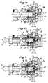
- Figures 7a, 7b and 7c show in section along VII-VII the device of Figure 3 in three positions, Figures 7b and 7c further showing the key of Figure 6 introduced into the system.
La figure 1 montre un camion citerne 1 muni d'une batterie de vannes 2a à 2k. Chaque vanne 2 correspond généralement à une cuve ou un compartiment du camion citerne et permet de transvaser le produit dudit compartiment à une cuve fixe munie d'une vanne telle que 3, au moyen d'un tuyau de dépotage 4.Figure 1 shows a tank truck 1 fitted with a battery of
Sur la figure 1, c'est la vanne 2a qui est en fonction et comme le montre ladite figure, la vanne 3 est reliée par l'intermédiaire d'une conduite flexible 6, à un dispositif 5a associé à ladite vanne 2a et dont il sera question plus en détail ci-après. La conduite 6 est aménagée pour être rangée au repos dans un support 7, par enroulement par exemple.In FIG. 1, the
La figure 2 montre l'une des vannes du camion, référencée par le chiffre général 2. Cette vanne 2 peut s'ouvrir et se fermer au moyen d'une poignée de manoeuvre 8. Toutefois, comme le montre la figure 2, la poignée 8 peut être bloquée à l'ouverture (qui se fait par une action de traction vers l'avant), par un vérin simple effet, qui constitue un système de verrouillage 9 pour ladite vanne.FIG. 2 shows one of the valves of the truck, referenced by the
Le système de verrouillage 9, et plus particulièrement le vérin qui le constitue, est relié, par une canalisation de commande schématisée en 10, à un dispositif de déverrouillage de référence générale 5 (figures 2, 3 et 4).The
Le dispositif de déverrouillage 5, est prévu pour recevoir l'extrémité de la conduite flexible 6 (figures 1 et 2).The
Le dispositif 5 est aménagé pour recevoir une pièce tubulaire 12, représentée en perspective de manière isolée sur la figure 5, tandis que l'extrémité de la conduite 6 est équipée d'une clef tubulaire 13 représentée de manière isolée sur la figure 6 et qui est destinée à être introduite dans la pièce tubulaire 12 (figures 2, 7a et 7b).The
Le dispositif 5 comporte un logement 14 (figure 4) pour recevoir une partie correspondante 14′ de la pièce 12 (figure 5) tandis qu'un moyen de blocage 15 (figures 3 et 4) est prévu pour bloquer et déverrouiller la pièce 12 qui est pourvue de moyens conjugués 15′ (figure 5), lesdits moyens pouvant aussi être du type à baïonnette par exemple, ou autres.The
Comme le montrent les figures 7a à 7c, la pièce 12 est pourvue de poussoirs à ressort référencés 16 et 17. A titre d'exemple, le poussoir 16 est un poussoir à ressort fendu et le poussoir 17 est un poussoir à ressort six pans.As shown in FIGS. 7a to 7c, the
Les poussoirs 16 et 17 sont destinés à constituer des moyens de retenue pour la clef 13 (figures 7b et 7c), lorsque celle-ci est pourvue de moyens conjugués sous forme d'une gorge 18 (figures 6).The
Les poussoirs 16 et 17 constituent pour la pièce 12, des moyens de reconnaissance et de retenue de la clef 13, lorsque celle-ci est pourvue de moyens conjugués. Il est donc clair que la clef peut être codée à volonté en fonction du produit à recevoir par la cuve dont la vanne 3 est reliée à la conduite 6, alors que de la même manière, la pièce 12 peut être codée en fonction du produit contenu dans le compartiment du camion qui correspond à la vanne 2 reliée par 9 au dispositif de déverrouillage pourvu de ladite pièce 12 (figure 2).The
Il est clair aussi que les codages sont faciles à réaliser dans les exemples représentés puisqu'il suffit de prévoir des poussoirs dans la pièce 12 et des gorges sur la clef 13 à des endroits choisis.It is also clear that the codings are easy to carry out in the examples shown since it suffices to provide pushers in the
Le dispositif 5 et plus généralement tous les dispositifs de déverouillage (5a à 5k; un par vanne camion) sont branchés sur le circuit pneumatique de servitude du camion au moyen d'un corps principal 19 qui est muni d'un alésage central dans lequel circule l'air du circuit selon la flèche F₁ (figures 7a, 7b, 7c).The
Dans le corps 19 (figures 7a à 7c) est prévue une pièce 20 qui est montée coulissante de manière étanche grâce à des joints toriques 21.In the body 19 (FIGS. 7a to 7c) is provided a
La pièce 20 est pourvue d'au moins un ajour tel que 22, ménagé de manière à communiquer avec l'alésage central du corps 19 (figures 7b et 7c) lorsque ladite pièce est suffisamment coulissée (vers la droite par rapport aux figures 7a à 7c) contre la sollicitation d'un ressort 23.The
En outre, la pièce 20 est munie d'un ergot 24 destiné à venir solliciter un clapet sphérique 25. Le clapet 25 est destiné, lorsqu'il est poussé par l'ergot 24, à mettre en communication l'alésage central du corps 19 avec une sortie 26 (figure 7c), cette dernière étant reliée à la canalisation de commande 10 (figure 2), tandis qu'un autre ressort 27 sollicite le clapet 25 à la fermeture. La pièce 20 est en outre munie d'une bague d'arrêt 28, destinée à venir en fin de course en butée sur le corps 19.In addition, the
La clef 13 est munie à son extrémité d'un passage 29 (figure 6) et la vanne 3 de la cuve fixe (figure 1) est pourvue d'un moyen d'ouverture tel un volant 11 verrouillé par un moyen 30, lequel peut être déverrouillé pneumatiquement. Comme le montre la figure 1, le moyen 30 est relié à la conduite 6.The key 13 is provided at its end with a passage 29 (FIG. 6) and the
Le fonctionnement est simple à comprendre.The operation is simple to understand.
Chaque vanne 3 est pourvue d'une conduite 6 et d'une clef 13, codée en fonction du produit à recevoir. Chaque dispositif 5 (5a à 5k sur la figure 1) est pourvu d'une pièce 12 codée en fonction du produit du compartiment correspondant de la citerne.Each
Au départ, la vanne 3 est verrouillée par le système 30 et chaque vanne 2 (2a à 2k) est bloquée par son système de verrouillage 9.At the start,
Pour procéder au dépotage, il y a lieu d'introduire la clef 13 de la conduite 6 dans la pièce 12 du dispositif 5 correspondant.To proceed with the unloading, it is necessary to introduce the key 13 of the
La figure 7a montre le dispositif avant l'introduction de la clef 13, l'air du circuit de servitude du camion traversant le corps 13 selon la flèche F₁.Figure 7a shows the device before the introduction of the key 13, the air of the truck service circuit passing through the
La figure 7b montre la clef 13 en position d'introduction partielle. Dans cette position, la pièce 20 poussée par l'extrémité de la clef 13 met en communication l'ajour 22 de la pièce 20 avec l'alésage central du corps 19. Le passage 29 de la clef 13 (figure 6) est aménagé de manière à se positionner sensiblement de manière coaxiale avec l'ajour 22 de la pièce 20 lorsque ladite clef est enfoncée à fond dans la pièce 12, de telle sorte que l'air du corps 19 parvient dans la clef 13, comme le montre la flèche F₂ des figures 7b et 7c.Figure 7b shows the key 13 in the partial insertion position. In this position, the
La clef 13 doit être poussée plus à fond pour prendre la position de la figure 7c et ouvrir le clapet 25 de manière à envoyer de l'air par 26 selon la flèche F₃.The key 13 must be pushed further to take the position of Figure 7c and open the
Il est clair que la clef 13 n'est maintenue dans la pièce 12 (figure 7c) que si les poussoirs 16, 17 correspondent à la gorge 18 de la clef.It is clear that the key 13 is only held in the part 12 (FIG. 7c) only if the
Dans la position de la figure 7c, de l'air sous pression est envoyé, d'une part, selon F₂ vers le système 30 de la vanne 3 via la conduite 6, ce qui permet un déverrouillage pneumatique dudit système 30 et, d'autre part, selon F₃ vers le système 9 via la conduite 10 (figure 2), ce qui permet un déverrouillage dudit système 9 et par conséquent, un dépotage possible entre le camion et la cuve fixe.In the position of Figure 7c, pressurized air is sent, on the one hand, according to F₂ to the
Si les compartiments ou cuves du camion sont destinés à recevoir des produits divers, il suffit à chaque remplissage du camion, de prévoir les pièces 12 convenables.If the compartments or tanks of the truck are intended to receive various products, it suffices each time the truck is filled, to provide the
Toutefois, en vue de faciliter cette opération, il est possible de prévoir une pièce 12 unique pourvue de plusieurs entrées et montée par exemple tournante pour permettre de sélectionner le codage en fonction de sa position angulaire.However, in order to facilitate this operation, it is possible to provide a
Le mode de réalisation décrit ci-avant est évidemment donné à titre d'exemple nullement limitatif.The embodiment described above is obviously given by way of nonlimiting example.
C'est ainsi que les moyens de codage peuvent être très divers, positions des pistons et/ou formes et sections diverses, ...This is how the coding means can be very diverse, positions of the pistons and / or various shapes and sections, ...
En outre, si le système pneumatique décrit paraît préférable, il pourrait bien sûr être hydraulique, et même électrique, la pièce 12 devant être considérée comme un moyen de reconnaissance codée d'une clef codée 13.Furthermore, if the pneumatic system described seems preferable, it could of course be hydraulic, and even electrical, the
Les systèmes de verrouillage des vannes côté camion pourraient aussi être, selon un mode de réalisation, un contrôle des clapets de fond des compartiments considérés, lesdits clapets étant actionnés par les dispositifs de déverrouillage.The valve side locking systems on the truck side could also, according to one embodiment, be a check of the bottom valves of the compartments considered, said valves being actuated by the unlocking devices.
Enfin, de nombreux aménagement sont envisageables, des couleurs particulières étant par exemple prévues pour les conduites 6 et les pièces 12 selon les produits, ...Finally, many arrangements are possible, particular colors being for example provided for the
Claims (9)
- Safety installation to prevent the mixing of products during discharging operations between at least one fixed tank and at least one mobile tanker each provided with at least one valve (3, 2) for filling or drainage respectively, characterised in that it comprises a key (13) which is coded according to the product to be discharged and which is connected by a linking means (6) to one (3) of the valves, that of the tank or of the tanker respectively, locking systems (9, 30) which are mounted on said valves, and an unlocking device (5) which is disposed in the vicinity of the other valve (2), that of the tanker or the tank respectively, and which comprises a recognition means (12) coded according to the product and so as to mate with said key, so as to actuate the unlocking of said locking systems when the coding of the recognition means corresponds to that of the key, the unlocking of the valve (3) connected by said linking means (6) being actuated via the latter.
- Installation according to claim 1, characterised in that the locking systems (9, 30) of the valves are disposed so as to be unlocked by the action of a fluid, in that the linking means is a flexible pipe (6), in that the unlocking device (5) is connected to a fluid supply circuit and in that the key (13) is disposed so as to enable the fluid of said supply circuit to actuate the unlocking of the locking systems when the key corresponds to the recognition means (12) of the unlocking device, which recognition means is disposed so as to receive and retain said key.
- Installation according to claim 2, characterised in that the key (13) is tubular and comprises at least one passage (29) at its end, while the unlocking device (5) comprises a valve with a double passage, designed to connect the fluid supply circuit, firstly, with the interior of the key (13) and thus with the locking system (30) of one of the valves (3), via the flexible pipe (6) and, secondly, with the locking system (9) of the other valve (2) which is provided with said unlocking device (5), via a control line (10).
- Installation according to claim 3, characterised in that the valve comprises a part (20) which is mounted slidingly and which is provided with at least one opening (22) designed to connect the supply circuit with the passage (29) of the key, through said opening of the part (20) when the latter is pushed by the key (13) against the action of an elastic means (23) which draws said part towards a closing position, while a valve (25) drawn towards the closing position by another elastic means (27) allows the supply circuit to be connected with the control line (10) when it is drawn against said other elastic means by at least one portion (24) of the sliding part.
- Installation according to one of claims 1 to 4, characterised in that the recognition means of the unlocking device is a receptacle (12) provided with retaining means (16, 17) disposed so as to mate with complementary means (18) of the key in order to retain the latter when said means co-operate with one another.
- Installation according to claim 5, characterised in that the receptacle (12) provided with the retaining means is fixed detachably so as to be able to be changed at will according to the product contained in the tanker or the tank respectively, the valve of which is equipped with the unlocking device.
- Installation according to claim 5, characterised in that the receptacle (12) provided with the retaining means is a moving part provided with a plurality of sets of retaining means, so as to make it possible to select one set of means according to the position of said moving part according to the product contained in the mobile tanker or the fixed tank respectively, the valve of which is equipped with the unlocking device.
- Installation according to one of claims 1 to 7, characterised in that a plurality of keys are connected to as many fixed tanks and in that the mobile tanker is a road tanker provided with a plurality of compartments each equipped with a valve (2a to 2k) and an unlocking device (5a to 5k), each key being coded according to the product to be received and each unlocking device being provided with a recognition means coded according to the product contained in the corresponding compartment.
- Installation according to all of claims 2 and 8, characterised in that the control fluid is air and the supply circuit is the pneumatic slave circuit of the road tanker.
Priority Applications (1)
| Application Number | Priority Date | Filing Date | Title |
|---|---|---|---|
| AT89401733TATE93211T1 (en) | 1988-06-21 | 1989-06-20 | SAFETY DEVICE TO PREVENT MIXING WHEN TRANSFERRING PRODUCTS BETWEEN A FIXED CONTAINER AND A TANK TRUCK. |
Applications Claiming Priority (2)
| Application Number | Priority Date | Filing Date | Title |
|---|---|---|---|
| FR8808281AFR2632942B1 (en) | 1988-06-21 | 1988-06-21 | ANTI-MIXTURE SECURITY SYSTEM FOR PRODUCTS DEPOSITED BETWEEN A FIXED TANK AND A MOBILE TANK |
| FR8808281 | 1988-06-21 |
Publications (2)
| Publication Number | Publication Date |
|---|---|
| EP0348294A1 EP0348294A1 (en) | 1989-12-27 |
| EP0348294B1true EP0348294B1 (en) | 1993-08-18 |
Family
ID=9367511
Family Applications (1)
| Application Number | Title | Priority Date | Filing Date |
|---|---|---|---|
| EP89401733AExpired - LifetimeEP0348294B1 (en) | 1988-06-21 | 1989-06-20 | Safety arrangement for preventing the mixing of products transferred between a fixed storage tank and a mobile reservoir |
Country Status (4)
| Country | Link |
|---|---|
| EP (1) | EP0348294B1 (en) |
| AT (1) | ATE93211T1 (en) |
| DE (1) | DE68908492T2 (en) |
| FR (1) | FR2632942B1 (en) |
Families Citing this family (3)
| Publication number | Priority date | Publication date | Assignee | Title |
|---|---|---|---|---|
| FR2666320B1 (en)* | 1990-08-29 | 1992-11-27 | Citaix | INSTALLATION TO AVOID MIXTURES WHEN DEPOSITING VARIOUS LIQUIDS FROM A MOBILE TANK TO AT LEAST ONE FIXED TANK. |
| GB2343492B (en)* | 1998-11-06 | 2000-09-27 | Kenneth Robert Smith | Improved fuel line coupling system |
| BE1022794B1 (en)* | 2015-04-27 | 2016-09-06 | Agriphar S.A. | IMPROVED METHOD FOR DISCHARGING AGROCHEMICAL PRODUCTS FROM TRANSPORT CONTAINERS AND RELATED PRODUCTS |
Family Cites Families (2)
| Publication number | Priority date | Publication date | Assignee | Title |
|---|---|---|---|---|
| GB2155532B (en)* | 1984-03-09 | 1987-12-16 | Sozaburo Maeshiba | Lock system preventing mixing of different kinds of oil at gasoline stand |
| DE3638293A1 (en)* | 1986-11-08 | 1988-05-19 | Sening Fa F A | Device for filling and emptying a transporting tank having a plurality of chambers for liquid products which are to be kept separate from one another |
- 1988
- 1988-06-21FRFR8808281Apatent/FR2632942B1/ennot_activeExpired - Lifetime
- 1989
- 1989-06-20DEDE89401733Tpatent/DE68908492T2/ennot_activeExpired - Fee Related
- 1989-06-20EPEP89401733Apatent/EP0348294B1/ennot_activeExpired - Lifetime
- 1989-06-20ATAT89401733Tpatent/ATE93211T1/ennot_activeIP Right Cessation
Also Published As
| Publication number | Publication date |
|---|---|
| DE68908492T2 (en) | 1994-01-27 |
| FR2632942B1 (en) | 1992-06-12 |
| FR2632942A1 (en) | 1989-12-22 |
| ATE93211T1 (en) | 1993-09-15 |
| EP0348294A1 (en) | 1989-12-27 |
| DE68908492D1 (en) | 1993-09-23 |
Similar Documents
| Publication | Publication Date | Title |
|---|---|---|
| US5301723A (en) | Apparatus and method of preventing ice accumulation on coupling valves for cryogenic fluids | |
| EP0644991B1 (en) | Coupling device | |
| EP0390715B1 (en) | Multiple fluidic connection | |
| CA2110274C (en) | Assembly for supplying commercial gas to a portable user apparatus | |
| EP3102866B1 (en) | Connection device for connecting two fluid circuits | |
| EP2265850A1 (en) | Fluid filling and/or extracting connector and assembly comprising a connector and a tap | |
| EP3693653B1 (en) | Device for supplying fluid under pressure and assembly for storing pressurised fluid including such a device | |
| EP3594508B1 (en) | Hydraulic circuit for supplying a cylinder, in particular used to manoeuvre a hold door of an aircraft | |
| EP0348294B1 (en) | Safety arrangement for preventing the mixing of products transferred between a fixed storage tank and a mobile reservoir | |
| EP0457700B1 (en) | Pipe line coupling device with rotating cocks | |
| EP0415311B1 (en) | Valve and device using the same | |
| FR2901482A1 (en) | OXYGEN FEEDING UNIT FOR AIRCRAFT. | |
| CA2978475A1 (en) | Device for supplying pressurised fluid and corresponding fluid transfer member | |
| EP2013421B1 (en) | Mixed unlocking coupler for heavy-construction machine | |
| FR2564082A1 (en) | LOCKING DEVICE FOR PREVENTING MIXING OF DIFFERENT TYPES OF HYDROCARBONS AT A FUEL STATION | |
| EP2283223A1 (en) | Pressurized gas receiving device, dispenser-receiving device assembly, and corresponding supply system | |
| EP1000635A1 (en) | Valve and portable permanently presurized fire extinguisher provided with such a valve | |
| EP2625093A1 (en) | Device for controlling the valves of a connector/disconnector | |
| FR2597815A1 (en) | ANTITHEFT FOR A MOTOR VEHICLE, OPERATING BY LOCKING THE FUEL PASSAGE | |
| EP0494818A1 (en) | Remote filling device of a lubricant container | |
| FR2772455A1 (en) | Discharge valve control and locking attachment for controlling the emptying of petroleum tankers | |
| BE1009300A3 (en) | Coupling for pipes intended for the flow of pressurised fluids | |
| FR2666320A1 (en) | System for preventing various liquids from mixing as they are transferred (decanted) from a tanker vehicle into at least one stationary tank | |
| FR2724709A1 (en) | Coupling for tap fitted to pressurised gas cylinder | |
| EP0898110A1 (en) | Actuating and locking device for a female coupling member and female coupling member having such a device |
Legal Events
| Date | Code | Title | Description |
|---|---|---|---|
| PUAI | Public reference made under article 153(3) epc to a published international application that has entered the european phase | Free format text:ORIGINAL CODE: 0009012 | |
| AK | Designated contracting states | Kind code of ref document:A1 Designated state(s):AT BE CH DE ES GB GR IT LI LU NL SE | |
| 17P | Request for examination filed | Effective date:19891215 | |
| 17Q | First examination report despatched | Effective date:19920227 | |
| GRAA | (expected) grant | Free format text:ORIGINAL CODE: 0009210 | |
| AK | Designated contracting states | Kind code of ref document:B1 Designated state(s):AT BE CH DE ES GB GR IT LI LU NL SE | |
| PG25 | Lapsed in a contracting state [announced via postgrant information from national office to epo] | Ref country code:IT Free format text:LAPSE BECAUSE OF FAILURE TO SUBMIT A TRANSLATION OF THE DESCRIPTION OR TO PAY THE FEE WITHIN THE PRE;WARNING: LAPSES OF ITALIAN PATENTS WITH EFFECTIVE DATE BEFORE 2007 MAY HAVE OCCURRED AT ANY TIME BEFORE 2007. THE CORRECT EFFECTIVE DATE MAY BE DIFFERENT FROM THE ONE RECORDED.SCRIBED TIME-LIMIT Effective date:19930818 Ref country code:NL Effective date:19930818 Ref country code:GR Free format text:LAPSE BECAUSE OF FAILURE TO SUBMIT A TRANSLATION OF THE DESCRIPTION OR TO PAY THE FEE WITHIN THE PRESCRIBED TIME-LIMIT Effective date:19930818 Ref country code:GB Effective date:19930818 Ref country code:AT Effective date:19930818 Ref country code:SE Effective date:19930818 Ref country code:ES Free format text:THE PATENT HAS BEEN ANNULLED BY A DECISION OF A NATIONAL AUTHORITY Effective date:19930818 | |
| REF | Corresponds to: | Ref document number:93211 Country of ref document:AT Date of ref document:19930915 Kind code of ref document:T | |
| REF | Corresponds to: | Ref document number:68908492 Country of ref document:DE Date of ref document:19930923 | |
| NLV1 | Nl: lapsed or annulled due to failure to fulfill the requirements of art. 29p and 29m of the patents act | ||
| GBV | Gb: ep patent (uk) treated as always having been void in accordance with gb section 77(7)/1977 [no translation filed] | Effective date:19930818 | |
| PLBE | No opposition filed within time limit | Free format text:ORIGINAL CODE: 0009261 | |
| STAA | Information on the status of an ep patent application or granted ep patent | Free format text:STATUS: NO OPPOSITION FILED WITHIN TIME LIMIT | |
| PG25 | Lapsed in a contracting state [announced via postgrant information from national office to epo] | Ref country code:LI Effective date:19940630 Ref country code:CH Effective date:19940630 | |
| EPTA | Lu: last paid annual fee | ||
| 26N | No opposition filed | ||
| REG | Reference to a national code | Ref country code:CH Ref legal event code:PL | |
| PGFP | Annual fee paid to national office [announced via postgrant information from national office to epo] | Ref country code:BE Payment date:20030528 Year of fee payment:15 | |
| PGFP | Annual fee paid to national office [announced via postgrant information from national office to epo] | Ref country code:LU Payment date:20030630 Year of fee payment:15 | |
| PGFP | Annual fee paid to national office [announced via postgrant information from national office to epo] | Ref country code:DE Payment date:20030822 Year of fee payment:15 | |
| PG25 | Lapsed in a contracting state [announced via postgrant information from national office to epo] | Ref country code:LU Free format text:LAPSE BECAUSE OF NON-PAYMENT OF DUE FEES Effective date:20040620 | |
| PG25 | Lapsed in a contracting state [announced via postgrant information from national office to epo] | Ref country code:BE Free format text:LAPSE BECAUSE OF NON-PAYMENT OF DUE FEES Effective date:20040630 | |
| BERE | Be: lapsed | Owner name:CIE INTERNATIONALE DE TRANSPORTS *CITAIX S.A. Effective date:20040630 | |
| PG25 | Lapsed in a contracting state [announced via postgrant information from national office to epo] | Ref country code:DE Free format text:LAPSE BECAUSE OF NON-PAYMENT OF DUE FEES Effective date:20050101 |