EP0347140B1 - Dual view endoscope - Google Patents
Dual view endoscopeDownload PDFInfo
- Publication number
- EP0347140B1 EP0347140B1EP89305899AEP89305899AEP0347140B1EP 0347140 B1EP0347140 B1EP 0347140B1EP 89305899 AEP89305899 AEP 89305899AEP 89305899 AEP89305899 AEP 89305899AEP 0347140 B1EP0347140 B1EP 0347140B1
- Authority
- EP
- European Patent Office
- Prior art keywords
- light
- endoscope according
- polarization
- field
- barrel
- Prior art date
- Legal status (The legal status is an assumption and is not a legal conclusion. Google has not performed a legal analysis and makes no representation as to the accuracy of the status listed.)
- Expired - Lifetime
Links
- 230000009977dual effectEffects0.000titleclaimsdescription7
- 230000005540biological transmissionEffects0.000claimsdescription41
- 230000010287polarizationEffects0.000claimsdescription41
- 239000004973liquid crystal related substanceSubstances0.000claimsdescription14
- 210000002858crystal cellAnatomy0.000claimsdescription10
- 230000003287optical effectEffects0.000claimsdescription10
- 239000011521glassSubstances0.000claimsdescription9
- 239000004988Nematic liquid crystalSubstances0.000claimsdescription8
- 230000000903blocking effectEffects0.000claimsdescription6
- 230000008878couplingEffects0.000claimsdescription3
- 238000010168coupling processMethods0.000claimsdescription3
- 238000005859coupling reactionMethods0.000claimsdescription3
- 239000010410layerSubstances0.000description15
- 239000011248coating agentSubstances0.000description9
- 238000000576coating methodMethods0.000description9
- 239000000463materialSubstances0.000description8
- 210000004027cellAnatomy0.000description7
- 230000000712assemblyEffects0.000description6
- 238000000429assemblyMethods0.000description6
- 230000005684electric fieldEffects0.000description4
- 238000010276constructionMethods0.000description3
- 238000005286illuminationMethods0.000description3
- 239000010409thin filmSubstances0.000description3
- 230000004913activationEffects0.000description2
- 229910052782aluminiumInorganic materials0.000description2
- XAGFODPZIPBFFR-UHFFFAOYSA-NaluminiumChemical compound[Al]XAGFODPZIPBFFR-UHFFFAOYSA-N0.000description2
- 230000007246mechanismEffects0.000description2
- 239000002356single layerSubstances0.000description2
- 125000006850spacer groupChemical group0.000description2
- 230000003595spectral effectEffects0.000description2
- 101000713585Homo sapiens Tubulin beta-4A chainProteins0.000description1
- 239000004809TeflonSubstances0.000description1
- 229920006362Teflon®Polymers0.000description1
- 102100036788Tubulin beta-4A chainHuman genes0.000description1
- 239000005083Zinc sulfideSubstances0.000description1
- 239000004568cementSubstances0.000description1
- 230000008859changeEffects0.000description1
- 229910001610cryoliteInorganic materials0.000description1
- 238000006073displacement reactionMethods0.000description1
- 239000010408filmSubstances0.000description1
- 239000003365glass fiberSubstances0.000description1
- 238000007689inspectionMethods0.000description1
- 210000003644lens cellAnatomy0.000description1
- 230000014759maintenance of locationEffects0.000description1
- 238000004519manufacturing processMethods0.000description1
- 229910052751metalInorganic materials0.000description1
- 239000002184metalSubstances0.000description1
- 238000000034methodMethods0.000description1
- 230000004048modificationEffects0.000description1
- 238000012986modificationMethods0.000description1
- 239000005304optical glassSubstances0.000description1
- 239000005342prism glassSubstances0.000description1
- 230000004044responseEffects0.000description1
- 230000000717retained effectEffects0.000description1
- 239000012780transparent materialSubstances0.000description1
- 238000001429visible spectrumMethods0.000description1
- 230000000007visual effectEffects0.000description1
- 229910052984zinc sulfideInorganic materials0.000description1
- DRDVZXDWVBGGMH-UHFFFAOYSA-Nzinc;sulfideChemical compound[S-2].[Zn+2]DRDVZXDWVBGGMH-UHFFFAOYSA-N0.000description1
Images
Classifications
- G—PHYSICS
- G02—OPTICS
- G02B—OPTICAL ELEMENTS, SYSTEMS OR APPARATUS
- G02B23/00—Telescopes, e.g. binoculars; Periscopes; Instruments for viewing the inside of hollow bodies; Viewfinders; Optical aiming or sighting devices
- G02B23/24—Instruments or systems for viewing the inside of hollow bodies, e.g. fibrescopes
- G02B23/2407—Optical details
- G02B23/2423—Optical details of the distal end
- A—HUMAN NECESSITIES
- A61—MEDICAL OR VETERINARY SCIENCE; HYGIENE
- A61B—DIAGNOSIS; SURGERY; IDENTIFICATION
- A61B1/00—Instruments for performing medical examinations of the interior of cavities or tubes of the body by visual or photographical inspection, e.g. endoscopes; Illuminating arrangements therefor
- A61B1/00163—Optical arrangements
- A61B1/00165—Optical arrangements with light-conductive means, e.g. fibre optics
- A—HUMAN NECESSITIES
- A61—MEDICAL OR VETERINARY SCIENCE; HYGIENE
- A61B—DIAGNOSIS; SURGERY; IDENTIFICATION
- A61B1/00—Instruments for performing medical examinations of the interior of cavities or tubes of the body by visual or photographical inspection, e.g. endoscopes; Illuminating arrangements therefor
- A61B1/00163—Optical arrangements
- A61B1/00174—Optical arrangements characterised by the viewing angles
- A61B1/00179—Optical arrangements characterised by the viewing angles for off-axis viewing
- A—HUMAN NECESSITIES
- A61—MEDICAL OR VETERINARY SCIENCE; HYGIENE
- A61B—DIAGNOSIS; SURGERY; IDENTIFICATION
- A61B1/00—Instruments for performing medical examinations of the interior of cavities or tubes of the body by visual or photographical inspection, e.g. endoscopes; Illuminating arrangements therefor
- A61B1/00163—Optical arrangements
- A61B1/00174—Optical arrangements characterised by the viewing angles
- A61B1/00181—Optical arrangements characterised by the viewing angles for multiple fixed viewing angles
- A—HUMAN NECESSITIES
- A61—MEDICAL OR VETERINARY SCIENCE; HYGIENE
- A61B—DIAGNOSIS; SURGERY; IDENTIFICATION
- A61B18/00—Surgical instruments, devices or methods for transferring non-mechanical forms of energy to or from the body
- A61B18/18—Surgical instruments, devices or methods for transferring non-mechanical forms of energy to or from the body by applying electromagnetic radiation, e.g. microwaves
- A61B18/20—Surgical instruments, devices or methods for transferring non-mechanical forms of energy to or from the body by applying electromagnetic radiation, e.g. microwaves using laser
- A61B18/22—Surgical instruments, devices or methods for transferring non-mechanical forms of energy to or from the body by applying electromagnetic radiation, e.g. microwaves using laser the beam being directed along or through a flexible conduit, e.g. an optical fibre; Couplings or hand-pieces therefor
- A61B2018/2255—Optical elements at the distal end of probe tips
- A61B2018/2272—Optical elements at the distal end of probe tips with reflective or refractive surfaces for deflecting the beam
Definitions
- Endoscopic instrumentsare widely known in which illumination of the field is provided by a fiberoptic cable or bundle that transmits light through the barrel of the endoscope to its distal end and in which visual images are then transmitted back to the physician through a series of lenses extending through the endoscope barrel from a field lens at the distal end to an eyepiece lens assembly at the endoscope's proximal end.
- the field lenscommonly faces in a forward or longitudinal direction, although a forward-oblique orientation is often provided.
- the practionermust usually remove the endoscope from the patient and replace it with another endoscope having side-viewing capability. It is believed apparent that endoscopic procedures would be rendered more effective and efficient if a single endoscope could be arranged so that the user could switch at will between two views (forward and lateral) of the inspection site without removing the endoscope from the patient.
- a variable field of view endoscopeis known from US-A-4,140,364 comprising a mechanically rotatable prism at the distal end permitting an observation over a wide angular range by varying the field of view by rotating said prism.
- One aspect of the present inventionlies in the recognition that mechanical schemes for achieving such an objective are not practical because the mechanisms are too complicated, occupy too much space, and are nearly impossible to fabricate economically.
- this inventionis based on the discovery that a relatively uncomplicated and highly-effective dual view endoscope may be achieved without any mechanical switching mechanism, or any separately movable parts, at the endoscope's distal end.
- Such resultsare accomplished by providing the endoscope with two fixed field lens assemblies at the endoscope's distal end, one assembly facing generally forwardly and the other laterally.
- Light received by the field lensesis directed through a beam combiner prism and then through an objective lens and a series of relay lenses back to the eyepiece lens assembly at the endoscope's proximal end.
- a control systemis provided for selectively blocking the transmission of light received by either of the field lens assemblies while allowing the transmission of light received by the other of those assemblies.
- the adjustable light transmission control meanstakes the form of polarizing filters for polarizing the light passing from the field lenses so that the orthological linear polarization of light from one of the field lens assemblies is at right angles to the polarization of light from the other assembly, and then providing the endoscope with an adjustable polarization-sensitive transmission filter interposed between the field lenses and the eyepiece for selectively blocking the transmission of polarized light from either one of the field lenses while transmitting polarized light from the other of such field lenses.
- the light transmission control meanstakes the form of a pair of liquid crystal filters interposed between the respective field lenses and the beam combiner prism, each of the liquid crystal filters being capable of being electrically activated to permit light from only a selected one of the two field lenses to enter the beam combiner prism at any one time.
- the light-polarizing meansmay comprise dichroic polarizers, or other suitable polarizing elements, at the exit faces of the field lenses.
- selective polarizationis produced by a multilayer dielectric reflector in the beam combiner prism.
- the polarization-sensitive transmission filtermay take the form of a dichroic polarization filter, or a thin-film multilayer polarization filter, or a MacNeille prism.
- Ninety degree rotation of the filter or prism within the proximal end portion of the endoscopemay be achieved by manually rotating an external collar that is mechnically or magnetically coupled to the polarization-sensitive transmission filter.
- that filtermay be fixed within the endoscope and a twisted nematic liquid crystal cell having glass plate electrodes may be used for electrically controlling the transmission of an image from one field lens assembly or the other.
- the numeral 10generally designates an endoscope having an elongated outer tube or barrel 11 with distal and proximal ends 11a and 11b, respectively. While the barrel would ordinarily be formed of rigid material, it may be of flexible construction as disclosed in U. S. patents 4,148,550 and 4,148,551.
- the proximal end of the outer barrelis secured within a tubular housing 12 to which a standard image-magnifying eyepiece lens assembly 13 is connected.
- Illumination for the field of viewis provided by a light-transmitting glass fiber bundle 14 that extends through substantially the full length of the outer barrel as shown in Figure 2.
- the bundleis operatively connected to a conventional light source 15, and the distal end of the bundle 14a is exposed to illuminate the field of view at the barrel's distal end 11a.
- Apertures 16 and 17are provided in the distal end of the tubular barrel, and field lenses 18 and 19 are secured within those apertures as illustrated most clearly in Figure 3.
- the orientation of the two field lensesmay be varied considerably according to the operating requirements of the instrument and the preferences of users.
- the laterally-facing field lens 18may be set at an angle within the range of 70 to 90° with respect to the longitudinal axis of the barrel (an angle of approximately 78° being shown), whereas the forwardly or distally facing field lens 19 may be set at an angle within the general range of 0 to 35° in relation to the same axis (an angle of about 26° being depicted).
- the locations of the two entrance apertures 16, 17, the angles of the chief rays for the field lenses, and the included cone angles of the ray bundlesshould be compatible with existing resectoscope and cystocope geometries so that the endoscope can fit into existing equipment without need to modify the equipment or replace it with special designs adapted for use with the dual view endoscope.
- FIG. 3illustrates only the chief rays 20 and 21 through field lenses 18 and 19, respectively.
- BCPbeam combiner prism
- the BCP 22comprises two prism elements 22a and 22b having coplanar faces cemented or sealed together with a suitable reflective-transmissive coating 23 therebetween.
- a coatingmay take the form of a thin (usually monomolecular) layer of aluminum or other suitable metal. The thickness of the aluminum layer is selected so that it reflects approximately half of the incident light and transmits the other half.
- the light passing through field lens 19follows the path of chief ray 21 where it undergoes a first internal reflection at 24 and is directed through coating 23 along light path 25. Approximately 50 percent of such light is transmitted by the coating and is again internally reflected at 26 where it is redirected proximally along the optical axis or axial light path 27 of the system.
- light passing through the other field lens 18is partially reflected and partially transmitted by coating 23, and the reflected moiety also follows path 25 and is internally reflected at 26 along the longitudinal axis of the lens system. It is to be noted that in each instance there is a double reflection of the rays from the field lenses as they pass through the BCP.
- Surface 28 of prism element 22ais both the entrance surface for the lateral rays from field lens 18 and the second reflecting surface for both the forward and the lateral rays.
- the most efficient way to accomplish this dual functionis to leave surface 28 uncoated with the second reflection at 26 being due to total internal reflection.
- Total internal reflectionis readily achieved because the angle of incidence on this surface for all rays will be large enough to insure achieving total internal reflection conditions with any of a wide variety of optical glasses.
- surface 28must not be anti-reflection coated. Thus, there will be about a 5 percent Fresnel reflection loss for the lateral rays 20 entering the system at surface 28.
- the BCPdirects light along path 27 towards the eyepiece 13 through objective lens 30 and a series of relay lenses 31.
- the objective and relay lensesare supported within an inner tubular barrel 32 fixed within the outer barrel 11 by mounting elements 33.
- Tubular spacers 34 within the inner barrelspace the lenses apart for the proper transmission of an image to the eyepiece assembly 13.
- the eyepiece lens assemblymay be entirely conventional and includes a lens group for achieving a desired degree of magnification of the image.
- such selectively adjustable light transmission control meanstakes the form of light polarizing elements 40, 41 between the respective field lenses 18, 19 and BCP 22, plus an adjustable polarization-sensitive transmission filter 42 within housing 12 near eyepiece 13.
- the polarizing elements or layers 40 and 41may be any conventional dichroic light polarizing means with the result that light from the lateral field entering BCP 22 will be polarized with its path axis at 90° with respect to the path axis of light entering the BCP from the forward field.
- Light from both fieldstherefore passes simultaneously along axis 27 towards the eyepiece but the light from the respective fields is encoded by polarization so that by selective adjustment of the polarization-sensitive transmission filter 42 only one image will be transmitted to eyepiece 13.
- the loss of light-transmitting efficiency produced by the combination of polarizers and beam combiner prismmay in some instances be considered objectionable.
- the BCPtransmits only 50 percent of the incident light, reflecting the remaining 50 percent of such light.
- the transmission of a given polarization statecannot exceed 50 percent, and 30-35 percent is a common value for commercially-available thin dichroic polarizers. Consequently, in the system thus described, the overall transmission from each field lens 18, 19 to the objective lens 30 via the BCP cannot exceed 25 percent.
- Such transmission lossmay be reduced by the preferred embodiment depicted in Figures 4 and 5.
- the constructionis identical to that shown in Figure 3 except that the separate elements or encoding means 40, 41 are eliminated and a multilayer dielectric reflector 123 is substituted for the previously described reflective-transmissive metallic monolayer 23.
- the multilayer 123performs both the polarizing functions of elements 40 and 41 and the beam-combining function of coating 23, but with greatly reduced loss of light transmission.
- image brightnessmay be approximately tripled, for any given level of illumination, when compared with the brightness of the image produced by the embodiment of Figure 3.
- the multilayer 123is constructed so that it reflects light polarized perpendicular to the plane of incidence (s polarization) and transmits light polarized in the plane of incidence (p polarization).
- s polarizationlight polarized perpendicular to the plane of incidence
- p polarizationtransmits light polarized in the plane of incidence
- Figure 4depicts a double reflection BCP with the included angle between the chief rays 20 and 21 of the two beams at the field lenses being less than 90°.
- the component of the lateral beam 20 which is p polarizedwill pass through the multilayer dielectric deflector 123 and will pass entirely out of the system.
- the component of the same lateral beam 20 that is s polarizedwill be reflected by multilayer 123 and pass on through the endoscope to the eyepiece where it will be observed as the image of the lateral object field.
- the p polarized component of the forward beam 21will pass through multilayer 123 and therefore on through the endoscope to the eyepiece where it will be observed as the image of the forward object field.
- the s polarized component of the forward beamwill be reflected from the multilayer and pass out of the system (or into a suitable absorbing layer, not shown, along the external or upper surface of prism element 22b). Consequently, only p polarized light from the lateral image and s polarized light from the forward image will be transmitted through the objective and relay lenses towards the eyepiece.
- the lateral object fieldwill be polarized in a horizontal direction whereas the forward image field will be polarized in a vertical direction with respect to the viewer.
- Figure 5schematically illustrates the multilayer dielectric reflector 123 which functions as a polarizing beam combiner.
- the beam combiner layersare deposited on prism element 22b and then, after coating, that prism element is joined by cement layer 124 to prism element 22a.
- n G , n H and n Lare selected so that Brewster's condition is satisfied at each of the dielectric interfaces for the appropriate angle of incidence. These angles are ⁇ GH for the glass-high index interface, ⁇ H for the high index low-index interfaces and the high index-glass interface, and ⁇ L for the low index-high index interfaces. P polarized light incident upon a refracting interface at Brewster's Angle will pass through the interface with reflection. Consequently, a multilayer constructed as described will transmit p polarized light with very little loss and almost no reflection.
- High reflection of s polarized lightis obtained simultaneously with high transmission of p polarized light by setting the thickness of each thin film layer to ⁇ /4 at the angle of propagation through the layer where ⁇ is the wavelength of light in the film layer.
- Broadband operationis obtained by optimizing one half of the multilayer stack for s polarized reflection at one wavelength and the other half of the multilayer for a different wavelength.
- the reflection of s polarized light and the transmission of p polarized lightcan exceed 90 percent.
- the overall transmission from field lens to objective lens via the BCPcan be 45 percent or greater, a factor of 2 to 3 above that obtainable with separate polarizing elements 40, 41 and a partially-reflecting metallic monolayer 23.
- the total number of dielectric layersmay range between 5 to 15 depending on factors such as the selected prism material (index n G ), the angle of incidence ( ⁇ GH ), the included angle of the light cone transmitted by the field lenses, the required polarization purity, the thin film optical coating materials used, and the spectral bandwidth.
- the spectral bandwidthwill usally be the visible spectrum from 0.5 ⁇ m in the ultraviolet to 0.76 ⁇ m in the near-infrared.
- the adjustable light transmission control meansincludes an adjustable polarization-sensitive transmission filter 42 within the endoscope housing 12 adjacent eyepiece lens assembly 13.
- the polarization-sensitive transmission filter 42may be a high quality dichroic polarizer, a multilayer filter (as already described), or a MacNeille prism polarizer (as described in aforementioned U. S. patent 2,403,731).
- Meansmust be provided for supporting filter 42 so that it can be rotated at least 90° about its optical axis so that in one extreme of rotation the light transmitted to the eyepiece is s polarized and in the other extreme of rotation only p polarized light is transmitted to the eyepiece.
- the viewer using the instrumentwill see either the lateral field or the forward field through the eyepiece.
- Figures 6 and 7illustrate a mechanical-magnetic coupling for manually rotating filter 42 into its selected positions of adjustment.
- the filteris supported within a tubular holder 50 that is coaxial with barrel 11 and eyepiece 13 and is carried by antifriction annular bearing elements 51 and 52 of Teflon or other suitable material.
- Magnet 53is mounted upon the tubular holder 50 and a second magnet 54 is carried by control ring or sleeve 55 that is rotatably mounted upon the housing 12.
- the filter holder 50By rotating the knurled external adjustment sleeve 90° in one direction or the other, the filter holder 50 will also rotate the same angular extent to alter the pass direction for filter 42 from p polarization to s polarization.
- a retention screw 56not only prevents axial displacement of the sleeve upon housing 12, but also limits the extent of rotation of the sleeve because of the circumferential extent of slot 57 in which it is received.
- FIG 8depicts a filter assembly 142 in the form of a dichroic polarizer 143 combined with a twisted nematic liquid crystal cell 144.
- Figure 9shows a similar twisted nematic crystal cell 144 in combination with a MacNeille prism 145 to form a filter assembly 142′. In both cases, filter assemblies 142 and 142′ would be located in the position discussed with respect to filter 42 but would be fixed rather than rotatably mounted.
- the fixed-position filter assembly 142, 142′would be oriented to pass p polarized light which, for the endoscope, is the forwardly-received image.
- the twisted nematic liquid crystal cell 144consists of a thin layer 146 (approximately 10 ⁇ m) of suitable nematic liquid crystal material between two glass plates 147 and 148 coated on their interior facing surfaces with a transparent conducting layer and sealed at their edges. The interior cell surfaces are treated to cause the uniaxial optic axis of the liquid crystal molecules to lie nearly parallel to these surfaces. By rotating (during manufacture) the two glass plates about their common normal axis, it is possible to cause the nematic optical axis to undergo a smooth and continuous 90° twist in the plane of the glass plates from one boundary surface to the other.
- Electrical leadsare provided to establish an alternating electric potential across the two transparent conducting electrodes (typically 5-6 volts, 60 Hertz, 10 microamperes). This establishes an electric field perpendicular to the glass plates and causes reorientation of the nematic molecules from orientation parallel to the plates to orientation parallel to the electric field (the "on" state).
- the twisted uniaxial molecular orientation of the nematic materialcauses the plane of polarization of an incident optical beam to rotate 90° in passing through the liquid crystal layer.
- the polarization of an incident optical fielddoes not change upon traversing the liquid crystal layer.
- the liquid crystal cellmay be adjusted electrically to select between 2 polarized images.
- the cellIn the "on" state, the cell does not alter the state of polarization of the light transmitted to the polarizer 143, 145; consequently, when the cell is "on” the p polarized (i.e., forwardly-received) image is visible to the viewer. Conversely, when the cell is in its "off” state, the polarization of the light transmitted through the cell to the polarizer 143, 145 is rotated 90°; hence, s polarized light becomes p polarized light, and vice versa, and the lateral field of view is visible to the user.
- the liquid crystal cells 147are not oriented normal to the incident light. The reason is that the apparent "untwisting" of the nematic material depends upon the angle of incidence. By orienting the cell at a slight angle in the range of 10 to 20° from the optical axis of the cell, the response of the system will be uniform over the included angle of the ray cone immerging from the eyepiece lens.
- Any suitable switching meansmay be provided for controlling the electrical field applied to filter assemblies 142, 142′.
- the rotatable control sleeve 55 and housing 12may be provided with suitable contacts (not shown) with the sleeve connected to a suitable source of alternating electrical energy 150 diagramatically illustrated in Figure 1, but it is to be understood that any other conventional switching means may be provided.
- a further embodiment of the inventionis identical to the construction as shown in Figure 3 except that elements 40 and 41 take the form of liquid crystal filters or shutters.
- liquid crystal filtersare well known in the art and may be either polarizing or non-polarizing. Electrical activation of each filter or shutter blocks the light from passing from the respective field lens into the BCP; hence, by selective activation of the liquid crystal filters, light from one field lens or the other (the lens associated with the unactivated filter) is allowed to pass to the eyepiece while the light associated with the activated filter is blocked. Since such liquid crystal filters control light entering the BCP from the field lenses, they also function as the adjustable light transmission control means, eliminating the need for a separate filter (such as 42) in the housing 12 of the endoscope.
- Figure 10depicts the distal end portion of a simplified dual view endoscope constructed in accordance with this invention.
- the right angle prismwas formed of Schott SS-5 glass with its coplanar surfaces coated with a broadband (450 nm to 700 nm) polarizing multilayer as follows: T p > 0.99; R p ⁇ 0.01; T s ⁇ 0.01; R s > 0.99.
- a relay lens systemcomposed of 3 relay lens cells each having a length of 56.4 mm (2.22 in) bridged by spacers each having a length of 48.5 mm (1.91 in) transmits the image through the barrel to the rotatable polarizing element and eyepiece.
- the eyepiecemay be a 10x Ramsden eyepiece as commercially available.
Landscapes
- Health & Medical Sciences (AREA)
- Life Sciences & Earth Sciences (AREA)
- Physics & Mathematics (AREA)
- Surgery (AREA)
- Optics & Photonics (AREA)
- Biomedical Technology (AREA)
- Public Health (AREA)
- Nuclear Medicine, Radiotherapy & Molecular Imaging (AREA)
- Pathology (AREA)
- Radiology & Medical Imaging (AREA)
- Veterinary Medicine (AREA)
- Engineering & Computer Science (AREA)
- Molecular Biology (AREA)
- Biophysics (AREA)
- Medical Informatics (AREA)
- Heart & Thoracic Surgery (AREA)
- Animal Behavior & Ethology (AREA)
- General Health & Medical Sciences (AREA)
- General Physics & Mathematics (AREA)
- Astronomy & Astrophysics (AREA)
- Endoscopes (AREA)
- Instruments For Viewing The Inside Of Hollow Bodies (AREA)
Description
- Endoscopic instruments are widely known in which illumination of the field is provided by a fiberoptic cable or bundle that transmits light through the barrel of the endoscope to its distal end and in which visual images are then transmitted back to the physician through a series of lenses extending through the endoscope barrel from a field lens at the distal end to an eyepiece lens assembly at the endoscope's proximal end. The field lens commonly faces in a forward or longitudinal direction, although a forward-oblique orientation is often provided. Where lateral viewing is desired, the practioner must usually remove the endoscope from the patient and replace it with another endoscope having side-viewing capability. It is believed apparent that endoscopic procedures would be rendered more effective and efficient if a single endoscope could be arranged so that the user could switch at will between two views (forward and lateral) of the inspection site without removing the endoscope from the patient.
- A variable field of view endoscope is known from US-A-4,140,364 comprising a mechanically rotatable prism at the distal end permitting an observation over a wide angular range by varying the field of view by rotating said prism. One aspect of the present invention lies in the recognition that mechanical schemes for achieving such an objective are not practical because the mechanisms are too complicated, occupy too much space, and are nearly impossible to fabricate economically.
- In brief, this invention is based on the discovery that a relatively uncomplicated and highly-effective dual view endoscope may be achieved without any mechanical switching mechanism, or any separately movable parts, at the endoscope's distal end. Such results are accomplished by providing the endoscope with two fixed field lens assemblies at the endoscope's distal end, one assembly facing generally forwardly and the other laterally. Light received by the field lenses is directed through a beam combiner prism and then through an objective lens and a series of relay lenses back to the eyepiece lens assembly at the endoscope's proximal end. A control system is provided for selectively blocking the transmission of light received by either of the field lens assemblies while allowing the transmission of light received by the other of those assemblies. In one embodiment, the adjustable light transmission control means takes the form of polarizing filters for polarizing the light passing from the field lenses so that the orthological linear polarization of light from one of the field lens assemblies is at right angles to the polarization of light from the other assembly, and then providing the endoscope with an adjustable polarization-sensitive transmission filter interposed between the field lenses and the eyepiece for selectively blocking the transmission of polarized light from either one of the field lenses while transmitting polarized light from the other of such field lenses. In another embodiment, the light transmission control means takes the form of a pair of liquid crystal filters interposed between the respective field lenses and the beam combiner prism, each of the liquid crystal filters being capable of being electrically activated to permit light from only a selected one of the two field lenses to enter the beam combiner prism at any one time.
- Where polarization is used for selectively controlling the transmission of an image from one field lens or the other, the light-polarizing means may comprise dichroic polarizers, or other suitable polarizing elements, at the exit faces of the field lenses. In a preferred form, selective polarization is produced by a multilayer dielectric reflector in the beam combiner prism. The polarization-sensitive transmission filter may take the form of a dichroic polarization filter, or a thin-film multilayer polarization filter, or a MacNeille prism. Ninety degree rotation of the filter or prism within the proximal end portion of the endoscope may be achieved by manually rotating an external collar that is mechnically or magnetically coupled to the polarization-sensitive transmission filter. Alternatively, that filter may be fixed within the endoscope and a twisted nematic liquid crystal cell having glass plate electrodes may be used for electrically controlling the transmission of an image from one field lens assembly or the other.
- The invention will now be described, by way of example, with reference to the accompanying drawings, in which:
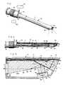
- Figure 1 is a perspective view of a dual-view endoscopic instrument embodying the invention.
- Figure 2 is a sectional longitudinal view of the instrument.
- Figure 3 is an enlarged fragmentary longitudinal sectional view of the distal end of the instrument.
- Figure 4 is a fragmentary sectional view similar to Figure 3 but illustrating a modified arrangement for polarizing light from the field lenses.
- Figure 5 is a greatly enlarged schematic view of the interface between the elements of the beam combiner prism used in the modification of Figure 4.
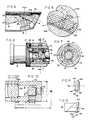
- Figure 6 is an enlarged fragmentary longitudinal sectional view of the proximal end of the instrument.
- Figure 7 is a cross sectional view taken along line 7-7 of Figure 6.
- Figure 8 illustrates a dichroic polarization filter in combination with a twisted nematic liquid crystal cell for use as the switching means of this invention.
- Figure 9 illustrates modified switching means in the form of a MacNeille prism in combination with a twisted nematic liquid crystal cell.
- Figure 10 is a fragmentary sectional view illustrating the distal end of a simplified but functional dual view endoscope embodying the invention.
- Referring to the drawings, the
numeral 10 generally designates an endoscope having an elongated outer tube or barrel 11 with distal and proximal ends 11a and 11b, respectively. While the barrel would ordinarily be formed of rigid material, it may be of flexible construction as disclosed in U. S. patents 4,148,550 and 4,148,551. The proximal end of the outer barrel is secured within atubular housing 12 to which a standard image-magnifyingeyepiece lens assembly 13 is connected. Illumination for the field of view is provided by a light-transmittingglass fiber bundle 14 that extends through substantially the full length of the outer barrel as shown in Figure 2. The bundle is operatively connected to aconventional light source 15, and the distal end of thebundle 14a is exposed to illuminate the field of view at the barrel's distal end 11a. Apertures field lenses field lens 18 may be set at an angle within the range of 70 to 90° with respect to the longitudinal axis of the barrel (an angle of approximately 78° being shown), whereas the forwardly or distally facingfield lens 19 may be set at an angle within the general range of 0 to 35° in relation to the same axis (an angle of about 26° being depicted). In general, for urological applications the locations of the twoentrance apertures - For clarity of illustration, Figure 3 illustrates only the
chief rays field lenses prism elements transmissive coating 23 therebetween. As is well known in BCP design, such a coating may take the form of a thin (usually monomolecular) layer of aluminum or other suitable metal. The thickness of the aluminum layer is selected so that it reflects approximately half of the incident light and transmits the other half. Thus, in the configuration shown in Figure 3, the light passing throughfield lens 19 follows the path ofchief ray 21 where it undergoes a first internal reflection at 24 and is directed throughcoating 23 alonglight path 25. Approximately 50 percent of such light is transmitted by the coating and is again internally reflected at 26 where it is redirected proximally along the optical axis oraxial light path 27 of the system. Similarly, light passing through theother field lens 18 is partially reflected and partially transmitted bycoating 23, and the reflected moiety also followspath 25 and is internally reflected at 26 along the longitudinal axis of the lens system. It is to be noted that in each instance there is a double reflection of the rays from the field lenses as they pass through the BCP.Surface 28 ofprism element 22a is both the entrance surface for the lateral rays fromfield lens 18 and the second reflecting surface for both the forward and the lateral rays. The most efficient way to accomplish this dual function is to leavesurface 28 uncoated with the second reflection at 26 being due to total internal reflection. Total internal reflection is readily achieved because the angle of incidence on this surface for all rays will be large enough to insure achieving total internal reflection conditions with any of a wide variety of optical glasses. However, to avoid frustrating such total internal reflection,surface 28 must not be anti-reflection coated. Thus, there will be about a 5 percent Fresnel reflection loss for thelateral rays 20 entering the system atsurface 28. - The BCP directs light along
path 27 towards theeyepiece 13 throughobjective lens 30 and a series ofrelay lenses 31. As depicted in Figure 2 the objective and relay lenses are supported within an innertubular barrel 32 fixed within the outer barrel 11 bymounting elements 33.Tubular spacers 34 within the inner barrel space the lenses apart for the proper transmission of an image to theeyepiece assembly 13. The eyepiece lens assembly may be entirely conventional and includes a lens group for achieving a desired degree of magnification of the image. - Although the images from both the lateral view and the forward view follow the same path through the lens train to the eyepiece, means are provided for preventing more than one image from being transmitted to the viewer at any given time. In one embodiment of the invention, such selectively adjustable light transmission control means takes the form of light polarizing
elements respective field lenses BCP 22, plus an adjustable polarization-sensitive transmission filter 42 withinhousing 12 neareyepiece 13. The polarizing elements orlayers field entering BCP 22 will be polarized with its path axis at 90° with respect to the path axis of light entering the BCP from the forward field. Light from both fields therefore passes simultaneously alongaxis 27 towards the eyepiece but the light from the respective fields is encoded by polarization so that by selective adjustment of the polarization-sensitive transmission filter 42 only one image will be transmitted toeyepiece 13. - While such a system is highly effective in encoding the images so that a user may, by adjusting
filter 42, select the desired image and reject the other image, the loss of light-transmitting efficiency produced by the combination of polarizers and beam combiner prism may in some instances be considered objectionable. Specifically, as already noted the BCP transmits only 50 percent of the incident light, reflecting the remaining 50 percent of such light. For an ideal polarizer, the transmission of a given polarization state cannot exceed 50 percent, and 30-35 percent is a common value for commercially-available thin dichroic polarizers. Consequently, in the system thus described, the overall transmission from eachfield lens objective lens 30 via the BCP cannot exceed 25 percent. - Such transmission loss may be reduced by the preferred embodiment depicted in Figures 4 and 5. The construction is identical to that shown in Figure 3 except that the separate elements or encoding means 40, 41 are eliminated and a multilayer
dielectric reflector 123 is substituted for the previously described reflective-transmissivemetallic monolayer 23. Themultilayer 123 performs both the polarizing functions ofelements coating 23, but with greatly reduced loss of light transmission. Specifically, image brightness may be approximately tripled, for any given level of illumination, when compared with the brightness of the image produced by the embodiment of Figure 3. - The
multilayer 123 is constructed so that it reflects light polarized perpendicular to the plane of incidence (s polarization) and transmits light polarized in the plane of incidence (p polarization). The means for obtaining polarization selective reflection is similar to that described in U. S. patent 2,403,731, the disclosure of which is incorporated by reference herein. - Like Figure 3, Figure 4 depicts a double reflection BCP with the included angle between the
chief rays lateral beam 20 which is p polarized will pass through the multilayerdielectric deflector 123 and will pass entirely out of the system. The component of thesame lateral beam 20 that is s polarized will be reflected bymultilayer 123 and pass on through the endoscope to the eyepiece where it will be observed as the image of the lateral object field. - In analogous manner, the p polarized component of the
forward beam 21 will pass throughmultilayer 123 and therefore on through the endoscope to the eyepiece where it will be observed as the image of the forward object field. The s polarized component of the forward beam will be reflected from the multilayer and pass out of the system (or into a suitable absorbing layer, not shown, along the external or upper surface ofprism element 22b). Consequently, only p polarized light from the lateral image and s polarized light from the forward image will be transmitted through the objective and relay lenses towards the eyepiece. At the eyepiece end of the endoscope, the lateral object field will be polarized in a horizontal direction whereas the forward image field will be polarized in a vertical direction with respect to the viewer. - Figure 5 schematically illustrates the multilayer
dielectric reflector 123 which functions as a polarizing beam combiner. As shown, the beam combiner layers are deposited onprism element 22b and then, after coating, that prism element is joined bycement layer 124 toprism element 22a. For purposes of illustration, the multilayer is of the type (HL)mH where m=2 and where H denotes a high index optically transparent material such as zinc sulfide with index nH and L denotes an index material such as cryolite with index nL. - The indices of the prism glass and the H and L layers, nG, nH and nL, respectively, are selected so that Brewster's condition is satisfied at each of the dielectric interfaces for the appropriate angle of incidence. These angles are ΘGH for the glass-high index interface, ΘH for the high index low-index interfaces and the high index-glass interface, and ΘL for the low index-high index interfaces. P polarized light incident upon a refracting interface at Brewster's Angle will pass through the interface with reflection. Consequently, a multilayer constructed as described will transmit p polarized light with very little loss and almost no reflection.
- High reflection of s polarized light is obtained simultaneously with high transmission of p polarized light by setting the thickness of each thin film layer to λ/4 at the angle of propagation through the layer where λ is the wavelength of light in the film layer. Broadband operation is obtained by optimizing one half of the multilayer stack for s polarized reflection at one wavelength and the other half of the multilayer for a different wavelength.
- In this preferred system, utilizing a multilayer
dielectric reflector 123 as the light polarizing means and as the coating for the beam combiner, the reflection of s polarized light and the transmission of p polarized light can exceed 90 percent. Hence, the overall transmission from field lens to objective lens via the BCP can be 45 percent or greater, a factor of 2 to 3 above that obtainable with separatepolarizing elements metallic monolayer 23. The total number of dielectric layers may range between 5 to 15 depending on factors such as the selected prism material (index nG), the angle of incidence (ΘGH), the included angle of the light cone transmitted by the field lenses, the required polarization purity, the thin film optical coating materials used, and the spectral bandwidth. For an endoscope, the spectral bandwidth will usally be the visible spectrum from 0.5 µm in the ultraviolet to 0.76 µm in the near-infrared. - As previously indicated, the adjustable light transmission control means includes an adjustable polarization-
sensitive transmission filter 42 within theendoscope housing 12 adjacenteyepiece lens assembly 13. The polarization-sensitive transmission filter 42 may be a high quality dichroic polarizer, a multilayer filter (as already described), or a MacNeille prism polarizer (as described in aforementioned U. S. patent 2,403,731). Means must be provided for supportingfilter 42 so that it can be rotated at least 90° about its optical axis so that in one extreme of rotation the light transmitted to the eyepiece is s polarized and in the other extreme of rotation only p polarized light is transmitted to the eyepiece. Depending on which position of adjustment the rotatable filter is in, the viewer using the instrument will see either the lateral field or the forward field through the eyepiece. - Figures 6 and 7 illustrate a mechanical-magnetic coupling for manually rotating
filter 42 into its selected positions of adjustment. The filter is supported within atubular holder 50 that is coaxial with barrel 11 andeyepiece 13 and is carried by antifrictionannular bearing elements Magnet 53 is mounted upon thetubular holder 50 and asecond magnet 54 is carried by control ring orsleeve 55 that is rotatably mounted upon thehousing 12. By rotating the knurled external adjustment sleeve 90° in one direction or the other, thefilter holder 50 will also rotate the same angular extent to alter the pass direction forfilter 42 from p polarization to s polarization. Aretention screw 56 not only prevents axial displacement of the sleeve uponhousing 12, but also limits the extent of rotation of the sleeve because of the circumferential extent ofslot 57 in which it is received. - Other means may be provided for achieving the desired rotation of filter pass direction which avoid the mechanical complications of physically rotating the polarization-sensitive transmission filter. Figure 8 depicts a
filter assembly 142 in the form of adichroic polarizer 143 combined with a twisted nematicliquid crystal cell 144. Figure 9 shows a similar twistednematic crystal cell 144 in combination with aMacNeille prism 145 to form afilter assembly 142′. In both cases,filter assemblies collar 55 may be retained as a switching element or other suitable switching means may be provided, as hereinafter described.) In each case, the fixed-position filter assembly liquid crystal cell 144 consists of a thin layer 146 (approximately 10 µm) of suitable nematic liquid crystal material between twoglass plates - Electrical leads (not shown) are provided to establish an alternating electric potential across the two transparent conducting electrodes (typically 5-6 volts, 60 Hertz, 10 microamperes). This establishes an electric field perpendicular to the glass plates and causes reorientation of the nematic molecules from orientation parallel to the plates to orientation parallel to the electric field (the "on" state).
- In the absence of the alternating electric potential established across the transparent conducting electrodes (the "off" state), the twisted uniaxial molecular orientation of the nematic material causes the plane of polarization of an incident optical beam to rotate 90° in passing through the liquid crystal layer. In the "on" state, because the nematic molecules are reoriented by the applied electric field so as to resolve the twisted molecular structure, the polarization of an incident optical field does not change upon traversing the liquid crystal layer. Thus, the liquid crystal cell may be adjusted electrically to select between 2 polarized images. In the "on" state, the cell does not alter the state of polarization of the light transmitted to the
polarizer polarizer - In Figures 8 and 9, the
liquid crystal cells 147 are not oriented normal to the incident light. The reason is that the apparent "untwisting" of the nematic material depends upon the angle of incidence. By orienting the cell at a slight angle in the range of 10 to 20° from the optical axis of the cell, the response of the system will be uniform over the included angle of the ray cone immerging from the eyepiece lens. - Any suitable switching means may be provided for controlling the electrical field applied to filter
assemblies rotatable control sleeve 55 andhousing 12 may be provided with suitable contacts (not shown) with the sleeve connected to a suitable source of alternatingelectrical energy 150 diagramatically illustrated in Figure 1, but it is to be understood that any other conventional switching means may be provided. - A further embodiment of the invention is identical to the construction as shown in Figure 3 except that
elements housing 12 of the endoscope. - As a further illustrative example, Figure 10 depicts the distal end portion of a simplified dual view endoscope constructed in accordance with this invention. Dimensions a through i as represented in that drawing are as follows in mm (inches): a = 9.5 (0.375), b = 3 (0.118) c = 12.7 (0.5), d = 15.6 (0.615), e = 2 (0.079), f = 5.3 (0.21), g = 3.4 (0.134), h = 1 (0.038), i = 4 (0.158).
- The right angle prism was formed of Schott SS-5 glass with its coplanar surfaces coated with a broadband (450 nm to 700 nm) polarizing multilayer as follows: Tp > 0.99; Rp < 0.01; Ts < 0.01; Rs > 0.99. A relay lens system composed of 3 relay lens cells each having a length of 56.4 mm (2.22 in) bridged by spacers each having a length of 48.5 mm (1.91 in) transmits the image through the barrel to the rotatable polarizing element and eyepiece. The eyepiece may be a 10x Ramsden eyepiece as commercially available.
- While in the foregoing we have disclosed details of the invention in considerable detail for purposes of illustration, it will be understood that many of these details may be varied without departing from the scope of the claims.
Claims (20)
- A dual view endoscope comprising an elongated outer tubular barrel (11) having proximal (11b) and distal (11a) ends and having optical entrance apertures (16,17) at its distal end; a first field lens (18) mounted within said distal end of said barrel having an optical axis extending in a first direction for receiving light through one of said apertures; a second field lens (19) mounted within said distal end having an optical axis extending in a second direction for receiving light through the other of said apertures; beam combining prism means (22) adjacent said field lenses for directing light therefrom along a single path in a proximal direction; an eyepiece lens assembly (13) at said proximal end of said barrel for the viewing of images transmitted thereto; objective and relay lens means (30,31) along said barrel for producing images and transmitting the same to said eyepiece lens assembly; and adjustable light transmission control means (40,41,42,142,142′) for selectively blocking the transmission to said eyepiece lens assembly of light received by either one of said first and second field lenses while allowing the transmission to said eyepiece lens assembly of light received by the other of said field lenses.
- An endoscope according to Claim 1 in which said adjustable light transmission control (42,142,142′) means comprises a first liquid crystal filter interposed between said first field lens (18) and said beam combining prism means (22), and a second liquid crystal filter interposed between said second field lens (19) and said beam combining prism means; each of said liquid crystal filters being capable of being electrically activated to permit light from only a selected one of said first and second field lenses to enter said beam combining prism means at any one time.
- An endoscope according to Claim 1 in which said adjustable light transmission control means (42,142,142′) comprises light polarizing means (40,41) for polarizing the light from said field lenses so that the orthological linear polarization from said first field lens (18) is at right angles to the orthological linear polarization from said second field lens (19); and an adjustable polarization-sensitive transmission filter (42) interposed between said beam combining prism means (22) and said eyepiece lens assembly (13) for selectively blocking the transmission of polarized light from either one of said field lenses while transmitting polarized light from the other of said field lenses.
- An endoscope according to Claim 3 in which said light polarizing means (40,41) comprises a multilayer dielectric reflector within said beam combining prism means (22) for simultaneously polarizing and combining the beams from said first (18) and second (19) field lenses.
- An endoscope according to Claim 3 in which said light polarizing means (40,41) comprises a pair of light polarizing filters between said first (18) and second (19) field lenses and said beam combining prism (22).
- An endoscope according to Claim 3 in which said polarization-sensitive transmission filter (42) is rotatably mounted in said barrel (11) for rotation between a first position in which it transmits polarized light from said first field lens (18) while blocking polarized light from said second field lens (19), and a second position in which it transmits polarized light from said second field lens while blocking polarized light from said first field lens.
- An endoscope according to Claim 6 in which said polarization-sensitive transmission filter (42) is a dichroic polarization filter.
- An endoscope according to Claim 6 in which said polarization-sensitive transmission filter (42) is a multilayer polarization filter.
- An endoscope according to Claim 6 in which said polarization-sensitive transmission filter (42) is a MacNeille prism.
- An endoscope according to Claim 3 in which said polarization-sensitive transmission filter (42) is fixed within said barrel (11) and comprises a dichroic polarization filter and a twisted nematic liquid crystal cell (144) having glass plate electrodes; and means for establishing an alternating electrical potential across said electrodes.
- An endoscope according to Claim 10 in which said polarization-sensitive transmission filter (42) is fixed within said barrel (11) and comprises a MacNeille prism (145) and a twisted nematic liquid crystal cell (144) having glass plate electrodes; and means for establishing an alternating electrical potential across said electrodes.
- An endoscope according to Claim 6 in which an external control ring (55) is rotatably mounted upon said barrel (11) adjacent said eyepiece lens assembly (13); and means operatively coupling said polarization-sensitive transmission filter (42) and said control ring (55) for simultaneous rotation.
- An endoscope according to Claim 12 in which said means for operatively coupling said polarization-sensitive transmission filter (42) and said control ring (55) comprises magnetic means.
- An endoscope according to any one of the preceding claim in which said first field lens (18) faces distally and said second field lens faces (19) laterally.
- An endoscope according to Claim 14 in which said first field lens (18) faces distally at an oblique angle of no more than 35° with respect to the longitudinal axis of said barrel (11).
- An endoscope according to Claim 14 or 15 in which said second field lens (19) faces laterally and distally at an angle within the range of 70 to 90° with respect to the longitudinal axis of said barrel (11).
- An endoscope according to any one of the preceding claim in which a fibre-optic light-transmitting bundle extends through said barrel (11) for transmitting light to said distal end (11a) for illuminating an external field viewed by said field lenses.
- An endoscope according to Claim 1 in which said beam combining prism means (22) comprises two double-reflection beam combining prism elements having a pair of coplanar faces cemented together with light reflective/transmissive means disposed therebetween.
- An endoscope according to Claim 18 in which said light reflective/transmissive means comprises a thin metallic layer (23) capable of reflecting a portion of the light, and transmitting another portion of the light, from each of said field lenses.
- An endoscope according to Claim 19 in which said light reflective/transmissive means is a multilayer dielectric reflector (123).
Applications Claiming Priority (2)
| Application Number | Priority Date | Filing Date | Title |
|---|---|---|---|
| US07/205,667US4846154A (en) | 1988-06-13 | 1988-06-13 | Dual view endoscope |
| US205667 | 1988-06-13 |
Publications (2)
| Publication Number | Publication Date |
|---|---|
| EP0347140A1 EP0347140A1 (en) | 1989-12-20 |
| EP0347140B1true EP0347140B1 (en) | 1993-02-24 |
Family
ID=22763147
Family Applications (1)
| Application Number | Title | Priority Date | Filing Date |
|---|---|---|---|
| EP89305899AExpired - LifetimeEP0347140B1 (en) | 1988-06-13 | 1989-06-12 | Dual view endoscope |
Country Status (5)
| Country | Link |
|---|---|
| US (1) | US4846154A (en) |
| EP (1) | EP0347140B1 (en) |
| JP (1) | JP2802098B2 (en) |
| CA (1) | CA1304640C (en) |
| DE (1) | DE68904991T2 (en) |
Cited By (13)
| Publication number | Priority date | Publication date | Assignee | Title |
|---|---|---|---|---|
| US7708713B2 (en) | 2004-06-29 | 2010-05-04 | Applied Medical Resources Corporation | Insufflating optical surgical instrument |
| DE102009020262A1 (en) | 2009-05-07 | 2010-11-11 | Olympus Winter & Ibe Gmbh | Lens for endoscope, has mirror provided in area of border surface, where movement of mirror enables passage of light paths into border surface or causes reflection of light paths into border surface |
| DE102009059004A1 (en) | 2009-12-17 | 2011-06-22 | Olympus Winter & Ibe GmbH, 22045 | Objective for endoscope, has switching device including prism for enabling switchable deflection of radiation path from distal objective parts into proximal objective part and beam deflection device introduced into radiation path |
| DE102011005256A1 (en) | 2011-03-08 | 2012-09-13 | Olympus Winter & Ibe Gmbh | Method and system for displaying video endoscopic image data of a video endoscope with discrete viewing directions |
| WO2012119694A1 (en) | 2011-03-08 | 2012-09-13 | Olympus Winter & Ibe Gmbh | Method and system for displaying video-endoscopic image data of a video endoscope |
| US8377090B2 (en) | 2002-05-16 | 2013-02-19 | Applied Medical Resources Corporation | Blunt tip obturator |
| US8506520B2 (en) | 2008-09-29 | 2013-08-13 | Applied Medical Resources Corporation | Trocar system with laparoscope gas channel |
| US8517977B2 (en) | 2006-10-06 | 2013-08-27 | Applied Medical Resources Corporation | Visual insufflation port |
| US8608769B2 (en) | 2001-09-24 | 2013-12-17 | Applied Medical Resources Corporation | Bladeless optical obturator |
| US8636759B2 (en) | 2001-09-24 | 2014-01-28 | Applied Medical Resources Corporation | Bladeless obturator |
| DE102014013594A1 (en) | 2013-11-26 | 2015-05-28 | Viimagic Gmbh | Endoscope with several viewing directions |
| US9254148B2 (en) | 2011-05-02 | 2016-02-09 | Applied Medical Resources Corporation | Low-profile surgical universal access port |
| US9265899B2 (en) | 2008-01-25 | 2016-02-23 | Applied Medical Resources Corporation | Insufflating access system |
Families Citing this family (118)
| Publication number | Priority date | Publication date | Assignee | Title |
|---|---|---|---|---|
| US5274405A (en)* | 1987-11-17 | 1993-12-28 | Concept Vision Systems, Inc. | Wide angle viewing system |
| US5123726A (en)* | 1989-10-14 | 1992-06-23 | Concept Vision Systems, Inc. | Stereoscopic viewing system and method |
| US4838247A (en)* | 1988-10-06 | 1989-06-13 | Baxter International, Inc. | Dual-view arthroscope |
| US5685820A (en)* | 1990-11-06 | 1997-11-11 | Partomed Medizintechnik Gmbh | Instrument for the penetration of body tissue |
| DE4035146A1 (en)* | 1990-11-06 | 1992-05-07 | Riek Siegfried | INSTRUMENT FOR PENETRATING BODY TISSUE |
| US5688261A (en)* | 1990-11-07 | 1997-11-18 | Premier Laser Systems, Inc. | Transparent laser surgical probe |
| US5190028A (en)* | 1991-02-04 | 1993-03-02 | Citation Medical Corporation | Method for manufacturing a disposable arthroscopic probe |
| US5188093A (en)* | 1991-02-04 | 1993-02-23 | Citation Medical Corporation | Portable arthroscope with periscope optics |
| US5722970A (en)* | 1991-04-04 | 1998-03-03 | Premier Laser Systems, Inc. | Laser surgical method using transparent probe |
| US5305736A (en)* | 1991-04-26 | 1994-04-26 | Asahi Kogaku Kogyo Kabushiki Kaisha | Distal end part of endoscope |
| CA2075267A1 (en)* | 1991-12-24 | 1993-06-25 | Michael Lafferty | Portable arthroscope with periscope optics |
| WO1994009694A1 (en)* | 1992-10-28 | 1994-05-11 | Arsenault, Dennis, J. | Electronic endoscope |
| US5573493A (en)* | 1993-10-08 | 1996-11-12 | United States Surgical Corporation | Endoscope attachment for changing angle of view |
| US5720761A (en)* | 1993-11-16 | 1998-02-24 | Worldwide Optical Trocar Licensing Corp. | Visually directed trocar and method |
| US5609562A (en)* | 1993-11-16 | 1997-03-11 | Worldwide Optical Trocar Licensing Corporation | Visually directed trocar and method |
| US5445142A (en)* | 1994-03-15 | 1995-08-29 | Ethicon Endo-Surgery, Inc. | Surgical trocars having optical tips defining one or more viewing ports |
| JP3668257B2 (en)* | 1994-05-17 | 2005-07-06 | オリンパス株式会社 | Multi-view direction endoscope |
| US5743846A (en)* | 1994-03-17 | 1998-04-28 | Olympus Optical Co., Ltd. | Stereoscopic endoscope objective lens system having a plurality of front lens groups and one common rear lens group |
| US5554100A (en)* | 1994-03-24 | 1996-09-10 | United States Surgical Corporation | Arthroscope with shim for angularly orienting illumination fibers |
| US5547455A (en)* | 1994-03-30 | 1996-08-20 | Medical Media Systems | Electronically steerable endoscope |
| US5649897A (en)* | 1994-11-02 | 1997-07-22 | Terumo Kabushiki Kaisha | Endoscope apparatus for compensating for change in polarization state during image transmission |
| US6184923B1 (en)* | 1994-11-25 | 2001-02-06 | Olympus Optical Co., Ltd. | Endoscope with an interchangeable distal end optical adapter |
| US5463712A (en)* | 1994-12-05 | 1995-10-31 | Cawood; Charles D. | Fiberoptic casing for endoscopes and method of making |
| US5591183A (en)* | 1995-04-12 | 1997-01-07 | Origin Medsystems, Inc. | Dissection apparatus |
| US5980549A (en)* | 1995-07-13 | 1999-11-09 | Origin Medsystems, Inc. | Tissue separation cannula with dissection probe and method |
| US7384423B1 (en) | 1995-07-13 | 2008-06-10 | Origin Medsystems, Inc. | Tissue dissection method |
| US5968065A (en) | 1995-07-13 | 1999-10-19 | Origin Medsystems, Inc. | Tissue separation cannula |
| AU2248497A (en)* | 1996-02-01 | 1997-08-22 | Heartport, Inc. | Stereoscopic endoscope |
| US6929481B1 (en)* | 1996-09-04 | 2005-08-16 | Immersion Medical, Inc. | Interface device and method for interfacing instruments to medical procedure simulation systems |
| NL1005068C2 (en)* | 1997-01-23 | 1998-07-27 | Ct Rrn Academisch Ziekenhuis U | Catheter system and a catheter forming part thereof. |
| US6099467A (en)* | 1998-03-27 | 2000-08-08 | Karl Storz Gmbh & Co. Kg | Device for positioning components within endoscopic systems |
| US5807237A (en)* | 1997-03-31 | 1998-09-15 | Tindel; Nathaniel L. | Endoscopic device |
| DE19736617A1 (en)* | 1997-08-22 | 1999-03-11 | Storz Karl Gmbh & Co | Endoscope lens |
| US6045000A (en)* | 1997-12-02 | 2000-04-04 | Rauworth; Barry Lee | Blow molded drum |
| EP1056388B1 (en) | 1998-02-19 | 2004-12-22 | California Institute Of Technology | Apparatus for providing spherical viewing during endoscopic procedures |
| US6210133B1 (en) | 1998-09-30 | 2001-04-03 | A-Med Systems, Inc. | Blood pump with sterile motor housing |
| DE19847913B4 (en)* | 1998-10-19 | 2005-09-22 | Ersa Gmbh | Apparatus and method for optical inspection, in particular concealed solder joints |
| US6110105A (en)* | 1999-02-03 | 2000-08-29 | Durell & Gitelis, Inc. | Variable view arthroscope |
| DE19910079C1 (en)* | 1999-03-08 | 2000-08-31 | Christian Gaertner | Device for viewing surgical and dental operations uses filter to allow through polarized light |
| EP1188089B1 (en) | 1999-06-18 | 2002-11-06 | Olympus Winter & Ibe Gmbh | Endoscope with magnetic bodies |
| US6364830B1 (en) | 1999-11-30 | 2002-04-02 | Durell & Gitelis, Inc. | Variable view arthroscope |
| IL134017A (en)* | 2000-01-13 | 2008-04-13 | Capsule View Inc | Camera for viewing inside intestines |
| US6471638B1 (en) | 2000-04-28 | 2002-10-29 | Origin Medsystems, Inc. | Surgical apparatus |
| US7175593B2 (en)* | 2000-08-30 | 2007-02-13 | Durell & Gitelis, Inc. | Variable view arthroscope with charge coupled device |
| US6929603B2 (en)* | 2000-08-30 | 2005-08-16 | Durell & Gitelis, Inc. | Variable view arthroscope |
| US6638216B1 (en) | 2000-08-30 | 2003-10-28 | Durell & Gitelis, Inc. | Variable view arthroscope |
| JP4533695B2 (en)* | 2003-09-23 | 2010-09-01 | オリンパス株式会社 | Treatment endoscope |
| JP4448339B2 (en)* | 2004-01-15 | 2010-04-07 | Hoya株式会社 | Stereoscopic rigid optical system |
| DE102004023024B4 (en)* | 2004-05-06 | 2007-03-01 | Olympus Winter & Ibe Gmbh | Endoscope optics with lateral fiber optic bundle |
| US20050279354A1 (en)* | 2004-06-21 | 2005-12-22 | Harvey Deutsch | Structures and Methods for the Joint Delivery of Fluids and Light |
| JP4779120B2 (en)* | 2004-07-02 | 2011-09-28 | 国立大学法人大阪大学 | Endoscope attachment and endoscope |
| US8585584B2 (en)* | 2004-10-11 | 2013-11-19 | Nitesh Ratnakar | Dual view endoscope |
| US8872906B2 (en) | 2005-01-05 | 2014-10-28 | Avantis Medical Systems, Inc. | Endoscope assembly with a polarizing filter |
| US8797392B2 (en) | 2005-01-05 | 2014-08-05 | Avantis Medical Sytems, Inc. | Endoscope assembly with a polarizing filter |
| US8289381B2 (en) | 2005-01-05 | 2012-10-16 | Avantis Medical Systems, Inc. | Endoscope with an imaging catheter assembly and method of configuring an endoscope |
| US8182422B2 (en) | 2005-12-13 | 2012-05-22 | Avantis Medical Systems, Inc. | Endoscope having detachable imaging device and method of using |
| IL166595A0 (en)* | 2005-01-31 | 2006-01-15 | Uri Neta | Image acquisition system |
| WO2007087421A2 (en)* | 2006-01-23 | 2007-08-02 | Avantis Medical Systems, Inc. | Endoscope |
| US8287446B2 (en) | 2006-04-18 | 2012-10-16 | Avantis Medical Systems, Inc. | Vibratory device, endoscope having such a device, method for configuring an endoscope, and method of reducing looping of an endoscope |
| EP2023795A2 (en) | 2006-05-19 | 2009-02-18 | Avantis Medical Systems, Inc. | Device and method for reducing effects of video artifacts |
| JP2010520778A (en)* | 2007-03-09 | 2010-06-17 | ユニヴァーシティ オブ ワシントン | Side-view scope and imaging method thereof |
| US8064666B2 (en) | 2007-04-10 | 2011-11-22 | Avantis Medical Systems, Inc. | Method and device for examining or imaging an interior surface of a cavity |
| US20090112061A1 (en)* | 2007-10-25 | 2009-04-30 | Dhs Company Ltd. | Endoscope capable of varying field of vision |
| US9005114B2 (en)* | 2008-04-14 | 2015-04-14 | Carnegie Mellon University | Articulated device with visualization system |
| US7821720B2 (en)* | 2008-05-22 | 2010-10-26 | General Electric Company | Endoscope objective lens with large entrance pupil diameter and high numerical aperture |
| US9101268B2 (en) | 2009-06-18 | 2015-08-11 | Endochoice Innovation Center Ltd. | Multi-camera endoscope |
| US11547275B2 (en) | 2009-06-18 | 2023-01-10 | Endochoice, Inc. | Compact multi-viewing element endoscope system |
| US9642513B2 (en) | 2009-06-18 | 2017-05-09 | Endochoice Inc. | Compact multi-viewing element endoscope system |
| US9101287B2 (en) | 2011-03-07 | 2015-08-11 | Endochoice Innovation Center Ltd. | Multi camera endoscope assembly having multiple working channels |
| US9713417B2 (en) | 2009-06-18 | 2017-07-25 | Endochoice, Inc. | Image capture assembly for use in a multi-viewing elements endoscope |
| US9901244B2 (en) | 2009-06-18 | 2018-02-27 | Endochoice, Inc. | Circuit board assembly of a multiple viewing elements endoscope |
| US11864734B2 (en) | 2009-06-18 | 2024-01-09 | Endochoice, Inc. | Multi-camera endoscope |
| US11278190B2 (en) | 2009-06-18 | 2022-03-22 | Endochoice, Inc. | Multi-viewing element endoscope |
| US8926502B2 (en) | 2011-03-07 | 2015-01-06 | Endochoice, Inc. | Multi camera endoscope having a side service channel |
| WO2010146587A1 (en) | 2009-06-18 | 2010-12-23 | Peer Medical Ltd. | Multi-camera endoscope |
| US9872609B2 (en) | 2009-06-18 | 2018-01-23 | Endochoice Innovation Center Ltd. | Multi-camera endoscope |
| US10165929B2 (en) | 2009-06-18 | 2019-01-01 | Endochoice, Inc. | Compact multi-viewing element endoscope system |
| US9706903B2 (en) | 2009-06-18 | 2017-07-18 | Endochoice, Inc. | Multiple viewing elements endoscope system with modular imaging units |
| US9492063B2 (en) | 2009-06-18 | 2016-11-15 | Endochoice Innovation Center Ltd. | Multi-viewing element endoscope |
| US12137873B2 (en) | 2009-06-18 | 2024-11-12 | Endochoice, Inc. | Compact multi-viewing element endoscope system |
| US9402533B2 (en) | 2011-03-07 | 2016-08-02 | Endochoice Innovation Center Ltd. | Endoscope circuit board assembly |
| TWI578949B (en)* | 2009-07-15 | 2017-04-21 | Medical Intubation Tech Corp | Endoscopic device and its image processing method |
| WO2011056766A2 (en)* | 2009-11-05 | 2011-05-12 | Boston Scientific Scimed, Inc. | Endoscope including a variable state optical member |
| US12220105B2 (en) | 2010-06-16 | 2025-02-11 | Endochoice, Inc. | Circuit board assembly of a multiple viewing elements endoscope |
| EP2618718B1 (en) | 2010-09-20 | 2020-04-15 | EndoChoice Innovation Center Ltd. | Multi-camera endoscope having fluid channels |
| US9560953B2 (en) | 2010-09-20 | 2017-02-07 | Endochoice, Inc. | Operational interface in a multi-viewing element endoscope |
| US20120088965A1 (en)* | 2010-10-12 | 2012-04-12 | Ethicon Endo-Surgery, Inc. | Magnetically manipulatable surgical camera with removable adhesion removal system |
| CN103403605A (en) | 2010-10-28 | 2013-11-20 | 恩多巧爱思创新中心有限公司 | Optical systems for multi-sensor endoscopes |
| US12204087B2 (en) | 2010-10-28 | 2025-01-21 | Endochoice, Inc. | Optical systems for multi-sensor endoscopes |
| CN107361721B (en) | 2010-12-09 | 2019-06-18 | 恩多巧爱思创新中心有限公司 | Flexible electronic circuit boards for multi-camera endoscopes |
| US11889986B2 (en) | 2010-12-09 | 2024-02-06 | Endochoice, Inc. | Flexible electronic circuit board for a multi-camera endoscope |
| US9320419B2 (en) | 2010-12-09 | 2016-04-26 | Endochoice Innovation Center Ltd. | Fluid channeling component of a multi-camera endoscope |
| DE102010056025A1 (en)* | 2010-12-27 | 2012-06-28 | Olympus Winter & Ibe Gmbh | Endoscope with a shaft tube |
| EP2672878B1 (en) | 2011-02-07 | 2017-11-22 | Endochoice Innovation Center Ltd. | Multi-element cover for a multi-camera endoscope |
| JP5318142B2 (en)* | 2011-03-31 | 2013-10-16 | 富士フイルム株式会社 | Electronic endoscope |
| EP2604172B1 (en) | 2011-12-13 | 2015-08-12 | EndoChoice Innovation Center Ltd. | Rotatable connector for an endoscope |
| CA2798716A1 (en) | 2011-12-13 | 2013-06-13 | Peermedical Ltd. | Removable tip endoscope |
| US9279722B2 (en) | 2012-04-30 | 2016-03-08 | Agilent Technologies, Inc. | Optical emission system including dichroic beam combiner |
| US9560954B2 (en) | 2012-07-24 | 2017-02-07 | Endochoice, Inc. | Connector for use with endoscope |
| CN102894947B (en)* | 2012-09-26 | 2015-04-15 | 无锡微奥科技有限公司 | Micro electromechanical system (MEMS) optical probe |
| DE102012111290A1 (en)* | 2012-11-22 | 2014-05-22 | Karl Storz Gmbh & Co. Kg | An endoscope with adjustable viewing direction |
| US10616491B2 (en) | 2013-02-01 | 2020-04-07 | Deka Products Limited Partnership | Endoscope with pannable camera and related method |
| JP6375309B2 (en) | 2013-02-01 | 2018-08-15 | デカ・プロダクツ・リミテッド・パートナーシップ | Endoscope with camera capable of panning |
| DE102013101336A1 (en)* | 2013-02-11 | 2014-08-14 | Pajunk GmbH Medizintechnologie | trocar |
| US9993142B2 (en) | 2013-03-28 | 2018-06-12 | Endochoice, Inc. | Fluid distribution device for a multiple viewing elements endoscope |
| US9986899B2 (en) | 2013-03-28 | 2018-06-05 | Endochoice, Inc. | Manifold for a multiple viewing elements endoscope |
| US10499794B2 (en) | 2013-05-09 | 2019-12-10 | Endochoice, Inc. | Operational interface in a multi-viewing element endoscope |
| WO2015142797A1 (en)* | 2014-03-17 | 2015-09-24 | Intuitive Surgical Operations, Inc. | Angled endoscope tip image capture unit |
| JP2016142956A (en)* | 2015-02-03 | 2016-08-08 | オリンパス株式会社 | Optical adapter and endoscope |
| DE102015213773A1 (en)* | 2015-07-22 | 2017-01-26 | Olympus Winter & Ibe Gmbh | Prism arrangement for an endoscope with lateral viewing direction and endoscope |
| DE102016010296B4 (en)* | 2016-08-24 | 2020-11-05 | Schölly Fiberoptic GmbH | Lens arrangement and endoscope |
| WO2019210227A1 (en) | 2018-04-26 | 2019-10-31 | Deka Products Limited Partnership | Endoscope with rotatable camera and related methods |
| CN113412443A (en)* | 2018-12-11 | 2021-09-17 | 新加坡国立大学 | Assembly and method for switching visual angle direction of camera |
| DE102019123053A1 (en)* | 2019-08-28 | 2021-03-04 | Olympus Winter & Ibe Gmbh | Endoscope with optical filter arrangement and use |
| EP4194052A4 (en)* | 2020-08-05 | 2024-05-08 | Asahi Intecc Co., Ltd. | LIGHT IRRADIATION DEVICE AND LIGHT IRRADIATION SYSTEM |
| US11206973B1 (en) | 2020-09-14 | 2021-12-28 | Kenneth Hiller | Laryngoscope |
| US12035886B2 (en)* | 2022-02-04 | 2024-07-16 | Olympus Medical Systems Corp. | Endoscope, insertion portion and distal-end constituting portion for use with endoscope |
| CN119033302A (en)* | 2024-10-31 | 2024-11-29 | 湖南省华芯医疗器械有限公司 | Front end assembly, insertion part and endoscope |
Family Cites Families (14)
| Publication number | Priority date | Publication date | Assignee | Title |
|---|---|---|---|---|
| US2403731A (en)* | 1943-04-01 | 1946-07-09 | Eastman Kodak Co | Beam splitter |
| US3711181A (en)* | 1971-03-05 | 1973-01-16 | Xerox Corp | Optical notch filter |
| JPS49130235A (en)* | 1973-04-16 | 1974-12-13 | ||
| JPS584481Y2 (en)* | 1973-06-23 | 1983-01-26 | オリンパス光学工業株式会社 | Naishikiyoushiyahenkankogakkei |
| US4066334A (en)* | 1975-01-06 | 1978-01-03 | National Research Development Corporation | Liquid crystal light deflector |
| JPS5389451A (en)* | 1977-01-18 | 1978-08-07 | Olympus Optical Co Ltd | Endoscope visual field direction changing attachment optical system |
| US4148550A (en)* | 1977-05-09 | 1979-04-10 | American Hospital Supply Corporation | Rod lens assembly and method of making the same |
| US4148551A (en)* | 1977-05-09 | 1979-04-10 | American Hospital Supply Corporation | Modular rod lens assembly and method of making the same |
| JPS569712A (en)* | 1979-07-06 | 1981-01-31 | Olympus Optical Co Ltd | Visual field direction changing optical system for slender image transmission system |
| JPS6053923A (en)* | 1983-09-05 | 1985-03-28 | Olympus Optical Co Ltd | Endoscope |
| DE3435369C2 (en)* | 1983-10-03 | 1986-06-19 | Olympus Optical Co., Ltd., Tokio/Tokyo | endoscope |
| JPS61261713A (en)* | 1985-05-16 | 1986-11-19 | Olympus Optical Co Ltd | Electornic endoscope device |
| JPS6214416U (en)* | 1985-07-10 | 1987-01-28 | ||
| US4699463A (en)* | 1985-11-01 | 1987-10-13 | Circon Corporation | Multidirectional viewing borescope |
- 1988
- 1988-06-13USUS07/205,667patent/US4846154A/ennot_activeExpired - Lifetime
- 1989
- 1989-06-08CACA000602180Apatent/CA1304640C/ennot_activeExpired
- 1989-06-12DEDE8989305899Tpatent/DE68904991T2/ennot_activeExpired - Fee Related
- 1989-06-12EPEP89305899Apatent/EP0347140B1/ennot_activeExpired - Lifetime
- 1989-06-13JPJP1148557Apatent/JP2802098B2/ennot_activeExpired - Lifetime
Cited By (24)
| Publication number | Priority date | Publication date | Assignee | Title |
|---|---|---|---|---|
| US8608769B2 (en) | 2001-09-24 | 2013-12-17 | Applied Medical Resources Corporation | Bladeless optical obturator |
| US9254125B2 (en) | 2001-09-24 | 2016-02-09 | Applied Medical Resources Corporation | Bladeless obturator |
| US8940009B2 (en) | 2001-09-24 | 2015-01-27 | Applied Medical Resources Corporation | Bladeless optical obturator |
| US8636759B2 (en) | 2001-09-24 | 2014-01-28 | Applied Medical Resources Corporation | Bladeless obturator |
| US9545248B2 (en) | 2002-05-16 | 2017-01-17 | Applied Medical Resources Corporation | Blunt tip obturator |
| US8608768B2 (en) | 2002-05-16 | 2013-12-17 | Applied Medical Resources Corporation | Blunt tip obturator |
| US8377090B2 (en) | 2002-05-16 | 2013-02-19 | Applied Medical Resources Corporation | Blunt tip obturator |
| US7708713B2 (en) | 2004-06-29 | 2010-05-04 | Applied Medical Resources Corporation | Insufflating optical surgical instrument |
| US8128590B2 (en) | 2004-06-29 | 2012-03-06 | Applied Medical Resources Corporation | Insufflating optical surgical instruments |
| US9155558B2 (en) | 2004-06-29 | 2015-10-13 | Applied Medical Resources Corporation | Insufflating optical surgical instrument |
| US8517977B2 (en) | 2006-10-06 | 2013-08-27 | Applied Medical Resources Corporation | Visual insufflation port |
| US9492062B2 (en) | 2006-10-06 | 2016-11-15 | Applied Medical Resources Corporation | Visual insufflation port |
| US9265899B2 (en) | 2008-01-25 | 2016-02-23 | Applied Medical Resources Corporation | Insufflating access system |
| US9358040B2 (en) | 2008-09-29 | 2016-06-07 | Applied Medical Resources Corporation | First-entry trocar system |
| US8506520B2 (en) | 2008-09-29 | 2013-08-13 | Applied Medical Resources Corporation | Trocar system with laparoscope gas channel |
| US9314266B2 (en) | 2008-09-29 | 2016-04-19 | Applied Medical Resources Corporation | First-entry trocar system |
| DE102009020262A1 (en) | 2009-05-07 | 2010-11-11 | Olympus Winter & Ibe Gmbh | Lens for endoscope, has mirror provided in area of border surface, where movement of mirror enables passage of light paths into border surface or causes reflection of light paths into border surface |
| DE102009059004A1 (en) | 2009-12-17 | 2011-06-22 | Olympus Winter & Ibe GmbH, 22045 | Objective for endoscope, has switching device including prism for enabling switchable deflection of radiation path from distal objective parts into proximal objective part and beam deflection device introduced into radiation path |
| DE102011005259A1 (en) | 2011-03-08 | 2012-09-13 | Olympus Winter & Ibe Gmbh | Method and system for displaying video endoscopic image data of a video endoscope |
| WO2012119687A1 (en) | 2011-03-08 | 2012-09-13 | Olympus Winter & Ibe Gmbh | Method and system for displaying video-endoscopic image data from a video-endoscope with discreet viewing directions |
| WO2012119694A1 (en) | 2011-03-08 | 2012-09-13 | Olympus Winter & Ibe Gmbh | Method and system for displaying video-endoscopic image data of a video endoscope |
| DE102011005256A1 (en) | 2011-03-08 | 2012-09-13 | Olympus Winter & Ibe Gmbh | Method and system for displaying video endoscopic image data of a video endoscope with discrete viewing directions |
| US9254148B2 (en) | 2011-05-02 | 2016-02-09 | Applied Medical Resources Corporation | Low-profile surgical universal access port |
| DE102014013594A1 (en) | 2013-11-26 | 2015-05-28 | Viimagic Gmbh | Endoscope with several viewing directions |
Also Published As
| Publication number | Publication date |
|---|---|
| JPH0232313A (en) | 1990-02-02 |
| EP0347140A1 (en) | 1989-12-20 |
| CA1304640C (en) | 1992-07-07 |
| DE68904991T2 (en) | 1993-06-09 |
| JP2802098B2 (en) | 1998-09-21 |
| US4846154A (en) | 1989-07-11 |
| DE68904991D1 (en) | 1993-04-01 |
Similar Documents
| Publication | Publication Date | Title |
|---|---|---|
| EP0347140B1 (en) | Dual view endoscope | |
| CA1312511C (en) | Dual-view arthroscope | |
| US5538497A (en) | Endoscope having parasitic light elements | |
| US4076018A (en) | Endoscopes | |
| US5005943A (en) | Rigid video-endoscope having a rotatable device for adjusting the orientation of an image relative to an image receiving device | |
| EP1315443B1 (en) | Variable view arthroscope | |
| US6069733A (en) | Stereomicroscope | |
| CA2534601C (en) | Optical system for variable direction of view instrument | |
| US5781341A (en) | Motorized tunable filter and motorized variable attenuator | |
| US6635010B1 (en) | Endoscope objective | |
| WO1992016865A1 (en) | Multifiber endoscope with multiple scanning modes to produce an image free of fixed pattern noise | |
| US4805028A (en) | Television camera for endoscopes provided with an optical low-pass filter | |
| JPH04253B2 (en) | ||
| US5425123A (en) | Multifiber endoscope with multiple viewing modes to produce an image free of fixed pattern noise | |
| JPH06169415A (en) | Image pickup device | |
| US4398788A (en) | Binocular viewing device | |
| US4969708A (en) | Fiberoptic endoscope | |
| EP0586148A2 (en) | Imaging endoscope and endoscopic method employing phase conjugate imaging techniques | |
| US6659942B2 (en) | Endoscope with a deflection system | |
| US5589977A (en) | Binocular tube assembly for a stereomicroscope | |
| JPS6091323A (en) | Tiltable microscope | |
| JPH0289017A (en) | Image pickup system | |
| US5101468A (en) | Line fiberoptic light control module | |
| JP2003505715A (en) | Single lens stereoscopic light valve and device | |
| JPH08227014A (en) | Tunable wavelength filter, manufacturing method thereof, and tunable light source |
Legal Events
| Date | Code | Title | Description |
|---|---|---|---|
| PUAI | Public reference made under article 153(3) epc to a published international application that has entered the european phase | Free format text:ORIGINAL CODE: 0009012 | |
| AK | Designated contracting states | Kind code of ref document:A1 Designated state(s):DE FR GB | |
| 17P | Request for examination filed | Effective date:19900213 | |
| 17Q | First examination report despatched | Effective date:19920514 | |
| GRAA | (expected) grant | Free format text:ORIGINAL CODE: 0009210 | |
| AK | Designated contracting states | Kind code of ref document:B1 Designated state(s):DE FR GB | |
| PG25 | Lapsed in a contracting state [announced via postgrant information from national office to epo] | Ref country code:FR Effective date:19930224 | |
| REF | Corresponds to: | Ref document number:68904991 Country of ref document:DE Date of ref document:19930401 | |
| EN | Fr: translation not filed | ||
| PLBE | No opposition filed within time limit | Free format text:ORIGINAL CODE: 0009261 | |
| STAA | Information on the status of an ep patent application or granted ep patent | Free format text:STATUS: NO OPPOSITION FILED WITHIN TIME LIMIT | |
| 26N | No opposition filed | ||
| REG | Reference to a national code | Ref country code:GB Ref legal event code:IF02 | |
| PGFP | Annual fee paid to national office [announced via postgrant information from national office to epo] | Ref country code:GB Payment date:20020612 Year of fee payment:14 | |
| PGFP | Annual fee paid to national office [announced via postgrant information from national office to epo] | Ref country code:DE Payment date:20020619 Year of fee payment:14 | |
| PG25 | Lapsed in a contracting state [announced via postgrant information from national office to epo] | Ref country code:GB Free format text:LAPSE BECAUSE OF NON-PAYMENT OF DUE FEES Effective date:20030612 | |
| PG25 | Lapsed in a contracting state [announced via postgrant information from national office to epo] | Ref country code:DE Free format text:LAPSE BECAUSE OF NON-PAYMENT OF DUE FEES Effective date:20040101 | |
| GBPC | Gb: european patent ceased through non-payment of renewal fee | Effective date:20030612 |