EP0346392B1 - Appliance for extracting juice and pulp from fruit and vegetables - Google Patents
Appliance for extracting juice and pulp from fruit and vegetablesDownload PDFInfo
- Publication number
- EP0346392B1 EP0346392B1EP88902866AEP88902866AEP0346392B1EP 0346392 B1EP0346392 B1EP 0346392B1EP 88902866 AEP88902866 AEP 88902866AEP 88902866 AEP88902866 AEP 88902866AEP 0346392 B1EP0346392 B1EP 0346392B1
- Authority
- EP
- European Patent Office
- Prior art keywords
- strainer
- mandrel
- rotor
- skirt
- blades
- Prior art date
- Legal status (The legal status is an assumption and is not a legal conclusion. Google has not performed a legal analysis and makes no representation as to the accuracy of the status listed.)
- Expired - Lifetime
Links
- 235000011389fruit/vegetable juiceNutrition0.000titleclaimsabstractdescription23
- 235000012055fruits and vegetablesNutrition0.000titleabstractdescription5
- 235000013311vegetablesNutrition0.000claimsdescription10
- 230000000149penetrating effectEffects0.000claimsdescription4
- 238000005728strengtheningMethods0.000claims1
- 235000013399edible fruitsNutrition0.000description19
- 238000003825pressingMethods0.000description8
- 235000020971citrus fruitsNutrition0.000description6
- 238000000605extractionMethods0.000description5
- 239000000463materialSubstances0.000description5
- 241000207199CitrusSpecies0.000description3
- 235000013305foodNutrition0.000description3
- 235000015192vegetable juiceNutrition0.000description3
- 230000000712assemblyEffects0.000description2
- 238000000429assemblyMethods0.000description2
- 238000004140cleaningMethods0.000description2
- 238000006073displacement reactionMethods0.000description2
- 230000000694effectsEffects0.000description2
- 235000015203fruit juiceNutrition0.000description2
- 230000005484gravityEffects0.000description2
- 238000000034methodMethods0.000description2
- 239000002245particleSubstances0.000description2
- 235000005979Citrus limonNutrition0.000description1
- 244000131522Citrus pyriformisSpecies0.000description1
- 240000006766Cornus masSpecies0.000description1
- 235000003363Cornus masNutrition0.000description1
- 241000196324EmbryophytaSpecies0.000description1
- 244000141359Malus pumilaSpecies0.000description1
- 241000219094VitaceaeSpecies0.000description1
- 235000021016applesNutrition0.000description1
- 235000021028berryNutrition0.000description1
- 235000019658bitter tasteNutrition0.000description1
- 238000005119centrifugationMethods0.000description1
- 239000000470constituentSubstances0.000description1
- 238000010276constructionMethods0.000description1
- 238000005520cutting processMethods0.000description1
- 230000001627detrimental effectEffects0.000description1
- 238000007599dischargingMethods0.000description1
- 239000000839emulsionSubstances0.000description1
- 238000001914filtrationMethods0.000description1
- 239000000796flavoring agentSubstances0.000description1
- 235000019634flavorsNutrition0.000description1
- 239000012530fluidSubstances0.000description1
- 235000021021grapesNutrition0.000description1
- 239000010903huskSubstances0.000description1
- 235000015110jelliesNutrition0.000description1
- 239000007788liquidSubstances0.000description1
- 210000000056organAnatomy0.000description1
- 230000003647oxidationEffects0.000description1
- 238000007254oxidation reactionMethods0.000description1
- 230000035515penetrationEffects0.000description1
- 238000002360preparation methodMethods0.000description1
- 239000003755preservative agentSubstances0.000description1
- 238000012797qualificationMethods0.000description1
- 230000000284resting effectEffects0.000description1
- 238000000926separation methodMethods0.000description1
- 238000007873sievingMethods0.000description1
- 235000019640tasteNutrition0.000description1
- 239000002699waste materialSubstances0.000description1
- 210000000707wristAnatomy0.000description1
Images


Classifications
- A—HUMAN NECESSITIES
- A47—FURNITURE; DOMESTIC ARTICLES OR APPLIANCES; COFFEE MILLS; SPICE MILLS; SUCTION CLEANERS IN GENERAL
- A47J—KITCHEN EQUIPMENT; COFFEE MILLS; SPICE MILLS; APPARATUS FOR MAKING BEVERAGES
- A47J19/00—Household machines for straining foodstuffs; Household implements for mashing or straining foodstuffs
- A47J19/02—Citrus fruit squeezers; Other fruit juice extracting devices
- A47J19/027—Centrifugal extractors
Definitions
- the subject of the present inventionis an apparatus for expressing fruit and vegetable juices, that is to say extracting the juice from it, in order to consume it, either directly or in the form of sorbets, jellies, coulis, jams, purees, etc., intended in particular, but not exclusively, to be mounted on an electrical household appliance of the food processor type.
- citrus fruitsIn the case of citrus fruits, it is also known to extract the juice by cutting the lemon or orange in half, and pressing the cut half on a cone.
- a citrus press of this typeis known in particular from FR-A-2 459 031.
- a rotor apparatusfor the extraction of fruit juice intended in particular for berries.
- the rotorrotates at high speed inside a fixed horizontal cylindrical sieve, the rotor projecting the fruit against the sieve, which causes their shredding and the passage of the juice through the sieve.
- US-A-2 481 848describes a vegetable juice extractor in which a slicing tool cuts the products which are then grated in the bottom of the working chamber and returned by centrifugal force against a sieve.
- the screenis driven by a drive shaft via a plate carrying a hub in contact with the shaft. But this device only works in a centrifuge.
- An object of the present inventionis an apparatus for processing all fruits and vegetables to extract the edible fluid parts.
- the apparatus for extracting the juice and the pulp of plant productscomprising a base containing an electric motor, a tank removably mounted on the base so that a motor shaft projects at the inside the tank being surrounded by a central chimney, a lockable cover on said tank and a vertical sieve whose wall is parallel to the cylindrical wall of the tank, the sieve comprising, a skirt penetrating inside the chimney around the motor shaft and without contact with it, see also US-A-2 481 848.
- This deviceis characterized in that a mandrel can be fixed on the motor shaft in two directions, one in one sieve remains stationary, and the other in which the sieve is rotated when the motor shaft is rotating and in that it includes interchangeable tools, mounted alternately on the motor shaft via the mandrel.
- the screenis never driven directly by the motor shaft. It is thus possible to use the device, either in a press or in a centrifuge by an appropriate assembly, depending on the nature of the product treated.
- the rotating toolcan be either a rotor rotating inside a fixed screen, or a rasp driven in rotation with the screen.
- the rotating toolcan also be a fruit press cone secured to the motor shaft.
- the bottom of the tankis inclined relative to the horizontal and corresponds with a juice evacuation pipe.
- the stalk and the waste such as skins and seedsremain inside the sieve, which does not pose any particular problem of bulk, in particular in domestic applications to which this device is more particularly intended, while the juice and pulp are extracted.
- the assemblyis designed to be simple to assemble and easy to maintain. Thanks to this device, fruit, vegetable juices, coulis or pastes can be consumed immediately which have a flavor unknown to date. Indeed, in the case of industrial preparations intended to combat the oxidation of preservatives alter the natural taste of the product.
- the press for expressing vegetable juicecomprising a base containing an electric motor whose shaft projects inside a tank removably mounted on the base and closed by a cover removably mounted on the tank, various tools that can be successively secured to the motor shaft, is characterized in that it comprises a fixed cylindrical screen, and a rotor carrying at least one blade, the outer edge extends to the vicinity of the screen.
- the bladesare preferably articulated on the hub.
- the present inventionalso relates to an automatic positioning device for a rotating member on a motor shaft intended in particular, but not exclusively, for household electrical appliances.
- the toolsare mounted on the motor shaft by various means such as nuts, pliers, or a snap. It is essential that tools rotating at high speed be firmly secured to the motor shaft. However, in particular in the case of household electrical appliances which are usually used by housewives without any particular technical qualification, it is desirable that the mounting of the various tools on the motor shaft be as simple as possible. This consideration is particularly valid when it comes to mounting, not a simple tool comprising a hub of an appropriate profile, but a more complex assembly made up of two or more cooperating members. with each other, in particular in the case of centrifuges.
- the present inventionalso aims to overcome the drawbacks of known fastening devices and to allow automatic positioning, at a given level, of a member rotating on a drive shaft. It also relates to an automatic positioning device for a rotary screen on a motor shaft by means of a mandrel whose internal profile corresponds to the external profile of the motor shaft, the rotary member being clipped onto the mandrel, characterized in that the screen has a threaded hub in the direction of rotation of the drive shaft, the mandrel having a thread in the direction of rotation of the drive shaft, the outside diameter of which corresponds to the inside diameter of the thread of the hub, l 'assembly being mounted inside a tank having a chimney whose inner diameter is greater than the outer diameter of the hub.
- ribsare provided at the upper part of the chimney, forming slots between which the ribs and the rotary member bear.
- the housewifehas only to place a rotary member inside the tank, the ribs of the member penetrating inside the grooves of the chimney, then to put the mandrel inside the 'organ. It is the rotation of the motor which will give the elements of the assembly the correct positioning.
- the mandrel which is placed on the motor shaftis threaded thereon and is rotated in the direction of rotation of the motor. Under the influence of this rotation, the mandrel descends inside the hub of the rotary member, until it abuts against the bottom of the chimney. At this time, it continues to rotate, but without axial displacement on the motor shaft. As a result, the hub of the rotary member is screwed onto the mandrel, which causes an axial displacement, the elevation of this member until it clicks into place with the mandrel.
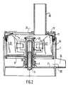
- the devicecomprises a tank 1 intended to be removably mounted on a base (not shown) containing the motor, by snap-fastening or by a bayonet closure.
- the bottom of the tank 2is inclined in the direction of an outlet neck 24, at an angle of a few degrees.
- the slopehas been considerably increased to facilitate understanding.
- the motor shaft 3rotated at a variable speed by the motor (not shown).
- the shaft 3passes inside the tank through a chimney 4, forming a baffle, intended to prevent the passage of the liquid and the pulp extracted from the fruits or vegetables along the drive shaft 3.
- a mandrelis mounted 5
- the extraction toolsare themselves mounted on this mandrel 5. They are made up, depending on the working method, or by a rotor 7 and a fixed screen 10, or by the same screen 10 movable in rotation, a grater 17 and possibly a fruit press cone 15.
- the mandrel 5has a series of 'pins or pins 6 of which only one appears in Figure 1 in the two possible positions.
- the screen 10is, for example, constituted by a ferrule pierced with holes whose dimensions are adapted to the work to be performed and which can, for example, be circular holes of 1 mm in diameter.
- the mandrel 5can be mounted and snapped onto the shaft 3 in two different positions.
- the first positionis shown on the right-hand side of FIG. 1 and in FIG. 2.
- the mandrel 5rotates a rotor 7 carrying pallets inside a stationary cage 8, constituted by a disc base 9, and a vertical cylindrical part comprising on at least part of its surface a screen 10, and a seal 11 fixed to the upper part of the screen 10, coming into contact with the internal surface of the cover 12.
- the cover 12is provided with a chute for introducing fruits or vegetables which will be described later.
- the hub or skirt 19 of the disc 9is mounted inside the chimney 4 without being driven by the drive shaft 3.
- the screen 10therefore remains fixed.
- the tool 7is rotated by the mandrel 5, the pins 6 thereof penetrating bayonet openings provided in the hub 22 of the rotor 7. It therefore rotates at the driving speed of the motor.
- the mandrel 5On the left part of FIG. 1, the mandrel 5 has been turned over relative to the position it occupied on the right part, that is to say that the lug (s) 6 are now located at the bottom of the mandrel 5 and, practically, just above the level of the chimney 4. They penetrate into the skirt or hub 19 of the disc 9. Thus, the mandrel 5 rotates the disc 9 and, consequently, the screen 10. Well Of course, the seal (not shown) must be lowered so that it no longer comes to bear on the cover. On the left-hand side of FIG.
- the cover 13has a funnel 14 and, in the central part, is mounted an extraction cone 15 which is fixed by means of a skirt 16 on the upper part of the mandrel 5
- the cone 15is thus also driven in rotation and it makes it possible to evacuate the pulp from the interior of a citrus fruit as well as the cores, the pulp falling on the grating disc 17 secured to the upper surface of the disc. 9, position from which it is discharged, by centrifugal force, on the screen 10 which performs the filtration of the juice.
- the mandrel 5is mounted in one position or the other, which corresponds to whether or not the screen 10 is driven in rotation. It is preferably clipped onto the tree 3.
- the apparatusincludes two separate covers.
- the cover 12(right part of Figure 1) is used when either pressing fruit or vegetables, or when centrifuging such food.
- the second cover 13(left part of FIG. 1) is used only in the case of the pressing of citrus fruits or the like on a cone 15.
- Figure 2shows the device in "press" function.
- the screen 10remains stationary.
- the disc 9is extended downwards by a skirt 19 which is locked inside the chimney 4 by interlocking.
- the lip seal 11, bearing against the internal surface of the cover 12also constitutes a blockage. In this case, it is mounted in the high position.
- the speed of such a toolcan vary from a few tens of revolutions per minute to about three thousand revolutions.
- itis the pressure of the blades which intervenes, while at higher speeds, the centrifugal force exerts its effects.
- a chute 20 for introducing the products to be pressedprotrudes from the upper surface of the cover 12 and surrounds an opening 21 provided in this cover.
- the chute 20opens into the part located between the hub 22 of the rotor and the blades 27 of the latter.
- a pusher(not shown) allows, by introduction into the chute, to push the fruit or vegetables down.
- the blades 27are mounted on the hub 22 by connections 23 which can be relatively flexible.
- a neck 24In the extension of the bottom 2 of the tank 1 is provided a neck 24. By this neck will come out, by gravity, the juice or the coulis, or puree of the fruits or vegetables which have been pressed against the sieve 10.
- the products to be pressedare introduced into the chute 20 after having been previously cut. During their rotation, the blades 27 exert pressure on the cut products, which forces the finest parts of these products to pass through the orifices of the grid 10.
- FIG. 5represents the rotor 7 consisting, as indicated above, of two blades 27 mounted on a hub 22 by connections 23.
- the material to be pressed falling in the tank 2arrives on one of the blades 27 and, due to the centrifugal force, slides on it to be somehow projected on the screen 10 against which it is pressed by the following blade .
- a space 32 of a few centimetersis formed between the lower part of the disc 9 and the bottom 2 of the tank so that rotation, either of the tool or of the screen, does not cause an emulsion of the juice which thus has the possibility of resting after its extraction.
- a fur 28is fixed which extends inside the tank by a part 29 to end in 30 immediately above the disc. 17.
- the productsare thus firstly grated, then by centrifugal force, ejected towards the wall 10 forming a sieve where the juice and the pulp are separated from the skin and the pits, these constituents remaining inside the tank.
- the seal 11can take, on the upper surface of the screen 10, two positions: a high position in which it comes into contact with the cover 12 (use in a press), and a low position in which its upper end is at a level lower than that of the lower face of the cover 12 (use in a centrifuge).
- the problem of contacting the seal 11is resolved by the use of a particular cover 13.
- the internal edge of the seal 11 located inside the tankis pierced with two series of openings (not shown), for example three, distributed at two different levels and which, by cooperation with pins (not shown) , formed at the top of the screen, allow the two desired levels of fixation to be obtained.
- the presence of the seal 11is not absolutely necessary. Indeed, the force exerted on the particles of fruit or vegetables is essentially radial. However, it is nevertheless desirable, in particular in the case where the seal is inclined as shown in the figures to play the role of deflector and bring towards the center the particles which could have accumulated in the top of the sieve without being suitably centrifuged.
- the edge of the funnel 14allows, in this embodiment, the fitting of the wrists, this which ensures good guidance of the fruit. It is also possible to use a cover 13 such as that shown in FIGS. 1 and 4. As indicated above, the rotation movement of the cone effortlessly allows the citrus husk to be ejected from a firstly the juice, secondly the pulp, and finally the pits or seeds. In this mounting method, the assembly first falls on the disc 17 which, by the action of centrifugal force, sends the products extracted from the envelope to the sieving surface 10.
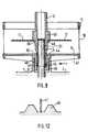
- FIG. 6which represents an apparatus used in a press, the tool is a rotor 7 rotating inside the vertical cylindrical screen 10. At the upper part of the screen 10 is provided a rolled edge 18 on which may come attach a seal 11. In all assemblies, the tool is snapped onto the motor shaft 3.
- Figures 7 and 8show the rotor 7, on the one hand in vertical cut view, and on the other hand in top view.
- the body 35 of the rotoris hollow and ends, at its lower part by a mandrel 5 intended to be secured on the motor shaft 3, inside the chimney 4. It has at its upper part a cap 22 which is intended for gripping the tool and extracting it from the shaft 3. Below the cap 22 extend two yokes 36 and 37, inside which are provided two holes 38, into which are introduced the pivot axes 23 of two blades 27.
- the structure of the bladesis such that the center of gravity of these is as far apart as possible so that the centrifugal force fully exerts its effects, that is to say that the blades 27 are thicker, and possibly denser, at their ends than in the vicinity of their axes .
- the blades 27are free around the axes 23. That is to say that, in the rest state, they assume any position relative to said axes (shown in dotted lines in FIG. 8).
- the centrifugal forceleads them to occupy a radial position, that is to say that they become diametrically opposite to each other (position shown in solid lines on Figure 8).
- This arrangementresults in a notable advantage. Indeed, during the pressing operation, it very often happens that one of the blades 27 is more loaded with pulp or residue than the second. Under these conditions, vibrations occur which are detrimental to the proper functioning of the machine.
- the blades 27are inclined from bottom to top at an angle which can vary from 6 to 12 degrees, so that the material to be pressed, which normally descends towards the bottom of the pressing chamber, is brought up by the rotation of the tool, so that the entire surface of the sieve is used.
- the rotary memberis constituted by the basket 10 of a centrifuge. This basket rotates inside a tank (not shown), of which only appears in the figure, the bottom 2 having a central orifice 1, inside which rises the motor shaft 3 surrounded by a chimney 4.
- the centrifuge screen 10has a skirt forming a hub 19 for rotating.
- a mandrel 5On the drive shaft is placed a mandrel 5, the lower part of which penetrates freely inside the thread 43 of the hub 19.
- the mandrel 5itself carries, above the skirt 45, a thread 44.
- the mandrel 5is moreover provided with latching means 46 constituted by elastic tabs and intended to hold the grating disc 17.
- the mandrel 5has a central bore 51, the lower part of which can end in one or two cut sides or even have a polygonal shape, so that the driving of the mandrel by the motor shaft 3 , is carried out without slipping.
- the Skirt 45advantageously has latching means (not shown) on the drive shaft.
- the basket 10has, at its lower part, stiffness ribs 47. Furthermore, the chimney 4 has, at its upper part, notches 48 (see FIG. 12) between which the ribs 47 of the basket 10 can come to bear.
- the ribs 47naturally come to bear between two slots 48, and the basket thus remains placed on the upper end of the chimney 4. Then the housewife introduces, inside the hub 19 of the basket 10, the mandrel 5, the skirt 45 of which penetrates inside the thread 43 of the hub 19 without being caught with the thread 43 and the grater 17.
- the engineis stopped and the mandrel assembly 5, basket 10, is extracted from the tank for cleaning.
- the mandrelcan be easily separated from the basket 10 by a slight traction followed by a rotational movement.
- threads 43 and 44are rapid threads so that the movements of descent of the mandrel 5, then of the hub 19 on the mandrel 5, are carried out in a fraction of a second.
- the device which has just been describedcan be implemented for any rotary member having a hub surrounding a removable mandrel.
Landscapes
- Engineering & Computer Science (AREA)
- Food Science & Technology (AREA)
- Apparatuses For Bulk Treatment Of Fruits And Vegetables And Apparatuses For Preparing Feeds (AREA)
- Centrifugal Separators (AREA)
- Food-Manufacturing Devices (AREA)
Abstract
Description
Translated fromFrenchLa présente invention a pour objet un appareil pour exprimer les jus de fruits et légumes, c'est-à-dire en extraire le suc, afin de consommer celui-ci, soit directement, soit sous la forme de sorbets, gelées, coulis, confitures, purées, etc..., destiné en particulier, mais non exclusivement, à être monté sur un appareil électro-ménager du type robot de cuisine.The subject of the present invention is an apparatus for expressing fruit and vegetable juices, that is to say extracting the juice from it, in order to consume it, either directly or in the form of sorbets, jellies, coulis, jams, purees, etc., intended in particular, but not exclusively, to be mounted on an electrical household appliance of the food processor type.
L'opération d'extraction des jus de fruits s'opère depuis des temps immémoriaux. Dans le cas du raisin et des pommes, l'extraction du jus se fait dans un pressoir, les fruits étant pressés contre une grille formant tamis, par l'intermédiaire d'un plateau, lui-même actionné par une vis de pression.The operation of extracting fruit juices has been carried out since time immemorial. In the case of grapes and apples, the juice is extracted in a press, the fruits being pressed against a grid forming a sieve, by means of a plate, itself actuated by a pressure screw.
Dans le cas des agrumes, il est également connu d'extraire le jus en coupant le citron ou l'orange en deux, et en pressant la moitié coupée sur un cône. Un presse-agrumes de ce type est connu notamment par FR-A-2 459 031.In the case of citrus fruits, it is also known to extract the juice by cutting the lemon or orange in half, and pressing the cut half on a cone. A citrus press of this type is known in particular from FR-A-2 459 031.
On connaît également par FR-A-80 00375 (GELB), un appareil à rotor pour l'extraction du jus de fruits destiné en particulier aux baies. Dans cet appareil, le rotor tourne à grande vitesse à l'intérieur d'un tamis cylindrique horizontal fixe, le rotor projetant les fruits contre le tamis, ce qui provoque leur dilacération et le passage du jus à travers le tamis.Also known from FR-A-80 00375 (GELB), a rotor apparatus for the extraction of fruit juice intended in particular for berries. In this device, the rotor rotates at high speed inside a fixed horizontal cylindrical sieve, the rotor projecting the fruit against the sieve, which causes their shredding and the passage of the juice through the sieve.
On connaît également, notamment par FR-A-2 129 193 (VERDUN), des centrifugeuses dans lesquelles le tamis est rotatif, la séparation du jus et de la pulpe s'effectuant par la force centrifuge.Also known, in particular from FR-A-2 129 193 (VERDUN), are centrifuges in which the sieve is rotary, the separation of the juice and the pulp being effected by centrifugal force.
US-A-2 481 848 décrit un extracteur de jus de végétaux dans lequel un outil éminceur effectue une coupe des produits qui sont ensuite râpés dans le fond de la chambre de travail et renvoyés par la force centrifuge contre un tamis. Le tamis est entraîné par un arbre moteur par l'intermédiaire d'une plaque portant un moyeu en contact avec l'arbre. Mais cet appareil ne fonctionne qu'en centrifugeuse.US-A-2 481 848 describes a vegetable juice extractor in which a slicing tool cuts the products which are then grated in the bottom of the working chamber and returned by centrifugal force against a sieve. The screen is driven by a drive shaft via a plate carrying a hub in contact with the shaft. But this device only works in a centrifuge.
Malheureusement, dans de telles centrifugeuses, les noyaux de certains fruits sont en partie concassés, de sorte qu'il peut subsister dans le jus une amertume désagréable.Unfortunately, in such centrifuges, the pits of some fruits are partly crushed, so that there may remain in the juice an unpleasant bitterness.
Mais chacun des appareils précités n'accomplit relativement bien le travail auquel il est destiné que pour une catégorie déterminée de fruits ou de légumes.But each of the aforementioned devices does relatively well the work for which it is intended only for a specific category of fruit or vegetables.
Un objet de la présente invention est un appareil permettant de traiter tous les fruits et légumes pour en extraire les parties fluides comestibles.An object of the present invention is an apparatus for processing all fruits and vegetables to extract the edible fluid parts.
Selon la présente invention, l'appareil d'extraction du jus et de la pulpe de produits végétaux comprenant un socle renfermant un moteur électrique, une cuve montée de manière amovible sur le socle de manière à ce qu'un arbre moteur fasse saillie à l'intérieur de la cuve en étant entouré par une cheminée centrale, un couvercle verrouillable sur ladite cuve et un tamis vertical dont la paroi est parallèle à la paroi cylindrique de la cuve, le tamis comprenant, une jupe pénétrant à l'intérieur de la cheminée autour de l'arbre moteur et sans contact avec celui-ci, voir aussi US-A-2 481 848. Cet appareil est caractérisé en ce qu'un mandrin peut être assujetti sur l'arbre moteur selon deux directions, l'une dans laquelle le tamis reste immobile, et l'autre dans laquelle le tamis est entraîné en rotation lorsque l'arbre moteur est en rotation et en ce qu'il comprends des outils interchangeables, montés alternativement sur l'arbre moteur par l'intermédiaire du mandrin.According to the present invention, the apparatus for extracting the juice and the pulp of plant products comprising a base containing an electric motor, a tank removably mounted on the base so that a motor shaft projects at the inside the tank being surrounded by a central chimney, a lockable cover on said tank and a vertical sieve whose wall is parallel to the cylindrical wall of the tank, the sieve comprising, a skirt penetrating inside the chimney around the motor shaft and without contact with it, see also US-A-2 481 848. This device is characterized in that a mandrel can be fixed on the motor shaft in two directions, one in one sieve remains stationary, and the other in which the sieve is rotated when the motor shaft is rotating and in that it includes interchangeable tools, mounted alternately on the motor shaft via the mandrel.
Le tamis n'est jamais entraîné directement par l'arbre moteur. Il est ainsi possible d'utiliser l'appareil, soit en pressoir, soit en centrifugeuse par un montage approprié, en fonction de la nature du produit traité.The screen is never driven directly by the motor shaft. It is thus possible to use the device, either in a press or in a centrifuge by an appropriate assembly, depending on the nature of the product treated.
Selon le type de fruits ou légumes à traiter, l'outil tournant peut être, soit un rotor tournant à l'intérieur d'un tamis fixe, soit une râpe entraînée en rotation avec le tamis. L'outil tournant peut également être un cône presse-fruit solidarisé de l'arbre moteur.Depending on the type of fruit or vegetable to be processed, the rotating tool can be either a rotor rotating inside a fixed screen, or a rasp driven in rotation with the screen. The rotating tool can also be a fruit press cone secured to the motor shaft.
Selon une autre caractéristique d'un mode de réalisation de l'invention, le fond de la cuve est incliné par rapport à l'horizontale et correspond avec un conduit d'évacuation du jus.According to another characteristic of an embodiment of the invention, the bottom of the tank is inclined relative to the horizontal and corresponds with a juice evacuation pipe.
En utilisant l'invention, la rafle et les déchets tels que peaux et pépins restent à l'intérieur du tamis, ce qui ne pose pas de problème d'encombrement particulier, notamment dans les applications domestiques auxquelles le présent appareil est plus particulièrement destiné, alors que sont extraits le jus et la pulpe. Bien entendu, l'ensemble est conçu pour être d'un montage simple et d'un entretien aisé. On obtient, grâce à cet appareil, des jus, des coulis ou des pâtes de fruits et légumes pouvant être consommés immédiatement qui ont une saveur inconnue jusqu'à ce jour. En effet, dans le cas des préparations industrielles destinées à combattre l'oxydation des conservateurs altèrent le goût naturel du produit.By using the invention, the stalk and the waste such as skins and seeds remain inside the sieve, which does not pose any particular problem of bulk, in particular in domestic applications to which this device is more particularly intended, while the juice and pulp are extracted. Of course, the assembly is designed to be simple to assemble and easy to maintain. Thanks to this device, fruit, vegetable juices, coulis or pastes can be consumed immediately which have a flavor unknown to date. Indeed, in the case of industrial preparations intended to combat the oxidation of preservatives alter the natural taste of the product.
Selon une autre caractéristique d'un mode de réalisation de la présente invention, le pressoir pour exprimer le jus de végétaux, comprenant un socle renfermant un moteur électrique dont l'arbre fait saillie à l'intérieur d'une cuve montée de manière amovible sur le socle et fermée par un couvercle monté de manière amovible sur la cuve, différents outils pouvant être assujettis successivement sur l'arbre moteur, est caractérisé en ce qu'il comprend un tamis cylindrique fixe, et un rotor portant au moins une pale dont le bord extérieur s'étend jusqu'au voisinage du tamis. Les pales sont, de préférence, articulées sur le moyeu.According to another characteristic of an embodiment of the present invention, the press for expressing vegetable juice, comprising a base containing an electric motor whose shaft projects inside a tank removably mounted on the base and closed by a cover removably mounted on the tank, various tools that can be successively secured to the motor shaft, is characterized in that it comprises a fixed cylindrical screen, and a rotor carrying at least one blade, the outer edge extends to the vicinity of the screen. The blades are preferably articulated on the hub.
La présente invention vise également un dispositif de positionnement automatique d'un organe tournant sur un arbre moteur destiné en particulier, mais non exclusivement, aux appareils électro-ménagers.The present invention also relates to an automatic positioning device for a rotating member on a motor shaft intended in particular, but not exclusively, for household electrical appliances.
Le montage des outils sur l'arbre moteur se fait par divers moyens tels que des écrous, des pinces, ou un encliquetage. Il est indispensable que les outils tournant à grande vitesse soient fermement assujettis sur l'arbre moteur. Or, en particulier dans le cas des appareils électro-ménagers qui sont habituellement utilisés par des ménagères sans qualification technique particulière, il est souhaitable que le montage des différents outils sur l'arbre moteur, soit le plus simple possible. Cette considération est particulièrement valable lorsqu'il s'agit de monter, non pas un simple outil comprenant un moyeu d'un profil approprié, mais un ensemble plus complexe composé de deux ou plusieurs organes coopérant l'un avec l'autre, dans le cas, en particulier, des centrifugeuses.The tools are mounted on the motor shaft by various means such as nuts, pliers, or a snap. It is essential that tools rotating at high speed be firmly secured to the motor shaft. However, in particular in the case of household electrical appliances which are usually used by housewives without any particular technical qualification, it is desirable that the mounting of the various tools on the motor shaft be as simple as possible. This consideration is particularly valid when it comes to mounting, not a simple tool comprising a hub of an appropriate profile, but a more complex assembly made up of two or more cooperating members. with each other, in particular in the case of centrifuges.
La présente invention a également pour objet de pallier les inconvénients des dispositifs de fixation connus et de permettre un positionnement automatique, à un niveau donné, d'un organe tournant sur un arbre moteur. Elle vise également un dispositif de positionnement automatique d'un tamis rotatif sur un arbre moteur par l'intermédiaire d'un mandrin dont le profil intérieur correspond au profil extérieur de l'arbre moteur, l'organe rotatif étant enclipsable sur le mandrin, caractérisé en ce que le tamis comporte un moyeu fileté dans le sens de rotation de l'arbre moteur, le mandrin comportant un filetage dans le sens de rotation de l'arbre moteur, dont le diamètre extérieur correspond au diamètre intérieur du filetage du moyeu, l'ensemble étant monté à l'intérieur d'une cuve présentant une cheminée dont le diamètre intérieur est supérieur au diamètre extérieur du moyeu.The present invention also aims to overcome the drawbacks of known fastening devices and to allow automatic positioning, at a given level, of a member rotating on a drive shaft. It also relates to an automatic positioning device for a rotary screen on a motor shaft by means of a mandrel whose internal profile corresponds to the external profile of the motor shaft, the rotary member being clipped onto the mandrel, characterized in that the screen has a threaded hub in the direction of rotation of the drive shaft, the mandrel having a thread in the direction of rotation of the drive shaft, the outside diameter of which corresponds to the inside diameter of the thread of the hub, l 'assembly being mounted inside a tank having a chimney whose inner diameter is greater than the outer diameter of the hub.
Selon une autre caractéristique d'un mode de réalisation de l'invention, des nervures sont prévues à la partie supérieure de la cheminée, formant des créneaux entre lesquels viennent prendre appui les nervures et l'organe rotatif.According to another characteristic of an embodiment of the invention, ribs are provided at the upper part of the chimney, forming slots between which the ribs and the rotary member bear.
Ainsi, la ménagère n'a qu'à poser un organe rotatif à l'intérieur de la cuve, les nervures de l'organe pénétrant à l'intérieur des rainures de la cheminée, puis à poser le mandrin à l'intérieur de l'organe. C'est la rotation du moteur qui va donner, aux éléments de l'assemblage, le positionnement convenable.Thus, the housewife has only to place a rotary member inside the tank, the ribs of the member penetrating inside the grooves of the chimney, then to put the mandrel inside the 'organ. It is the rotation of the motor which will give the elements of the assembly the correct positioning.
En effet, le mandrin qui est posé sur l'arbre moteur s'enfile sur celui-ci et est entraîné en rotation dans le sens de rotation du moteur. Sous l'influence de cette rotation, le mandrin descend à l'intérieur du moyeu de l'organe rotatif, jusqu'à ce qu'il vienne en butée contre le fond de la cheminée. A ce moment, il continue à tourner, mais sans déplacement axial sur l'arbre moteur. Par suite, le moyeu de l'organe rotatif se visse sur le mandrin, ce qui provoque par un déplacement axial, l'élévation de cet organe jusqu'à son encliquetage avec le mandrin.Indeed, the mandrel which is placed on the motor shaft is threaded thereon and is rotated in the direction of rotation of the motor. Under the influence of this rotation, the mandrel descends inside the hub of the rotary member, until it abuts against the bottom of the chimney. At this time, it continues to rotate, but without axial displacement on the motor shaft. As a result, the hub of the rotary member is screwed onto the mandrel, which causes an axial displacement, the elevation of this member until it clicks into place with the mandrel.
Lorsque le travail est terminé, le moteur étant arrêté, la ménagère retire l'ensemble mandrin - organe rotatif, et les sépare en vue de leur nettoyage.When the work is finished, the engine stopped, the housewife removes the chuck - rotary member assembly, and separates them for cleaning.
D'autres caractéristiques et avantages apparaîtront au cours de la description qui va suivre de modes particuliers de réalisation, donnés uniquement à titre d'exemples non limitatifs, en regard des dessins sur lesquels :
- la figure.1 est constituée par l'assemblage de deux demi-coupes de l'appareil assurant, pour la partie de droite, la fonction de pressoir, et pour la partie de gauche, la fonction de centrifugeuse presse-agrume ;
- la figure 2 est une coupe verticale du montage de l'appareil en pressoir ;
- la figure 3 est constituée de deux demi-coupes, la partie droite de la figure représentant l'utilisation de l'appareil en position centrifugeuse, et la partie gauche l'appareil en position presse-agrume/centrifugeuse ;
- la figure 4, une vue du couvercle presse-fruit ;
- la figure 5 est une vue en perspective du rotor ;
- la figure.6, une coupe verticale de la partie supérieure d'une machine fonctionnant en pressoir ;
- la figure 7, une vue en élévation d'un rotor ;
- la figure 8, une vue par-dessus du même rotor ;
- la figure.9, une vue de l'ensemble en coupe verticale avant mise en rotation du moteur ;
- la figure 10, une vue également en coupe verticale de l'ensemble, après mise en route du moteur ;
- la figure 11, une vue en coupe verticale de l'appareil en position de fonctionnement ;
- la figure 12, une vue de détail d'une nervure à l'intérieur de la couronne crénelée de la jupe de l'appareil.
- Figure.1 consists of the assembly of two half-sections of the device ensuring, for the right part, the press function, and for the left part, the function of juicer juicer;
- Figure 2 is a vertical section of the assembly of the press device;
- Figure 3 consists of two half-sections, the right part of the figure showing the use of the apparatus in the centrifuge position, and the left part the apparatus in the juicer / centrifuge position;
- Figure 4, a view of the fruit press cover;
- Figure 5 is a perspective view of the rotor;
- Figure.6, a vertical section of the upper part of a machine operating in press;
- Figure 7, an elevational view of a rotor;
- Figure 8, a top view of the same rotor;
- FIG. 9, a view of the assembly in vertical section before the engine is rotated;
- Figure 10, a view also in vertical section of the assembly, after starting the engine;
- Figure 11, a vertical sectional view of the apparatus in the operating position;
- Figure 12, a detail view of a rib inside the crenellated crown of the skirt of the device.
Sur la figure 1, on voit que l'appareil comprend une cuve 1 destinée à être montée d'une manière amovible sur un socle (non représenté) renfermant le moteur, par encliquetage ou par une fermeture a baïonnette. Le fond de la cuve 2 est incliné en direction d'un goulet de sortie 24, d'un angle de quelques degrés. Sur la figure 1, la pente a été considérablement augmentée pour faciliter la compréhension. On distingue sur la figure 1, l'arbre moteur 3, entraîné en rotation à une vitesse variable par le moteur (non représenté).In Figure 1, we see that the device comprises a tank 1 intended to be removably mounted on a base (not shown) containing the motor, by snap-fastening or by a bayonet closure. The bottom of the
L'arbre 3 passe à l'intérieur de la cuve à travers une cheminée 4, formant chicane, destinée à éviter le passage du liquide et de la pulpe extraits des fruits ou légumes le long de l'arbre moteur 3. Sur l'arbre moteur 3 dont la section externe présente une forme soit polygonale, soit circulaire avec un pan coupé, est monté un mandrin 5 Les outils d'extraction sont eux-mêmes montés sur ce mandrin 5. Ils sont constitués, selon le mode de travail, soit par un rotor 7 et un tamis fixe 10, soit par le même tamis 10 mobile en rotation, une râpe 17 et éventuellement un cône presse-fruit 15. Afin de permettre un entraînement sans glissement de ces outils, le mandrin 5 présente une série d'ergots ou de tétons 6 dont un seul apparaît sur la figure 1 dans les deux positions possibles. Le tamis 10 est, par exemple, constitué par une virole percée de trous dont les dimensions sont adaptées au travail à effectuer et qui peuvent, par exemple, être des trous circulaires de 1 mm de diamètre.The
Conformément à une caractéristique de l'invention, le mandrin 5 peut être monté et encliqueté sur l'arbre 3 en deux positions différentes. La première position est représentée sur la partie droite de la figure 1 et sur la figure 2. Dans cette position, le mandrin 5 entraîne en rotation un rotor 7 portant des palettes à l'intérieur d'une cage 8 immobile, constituée par un disque de base 9, et une partie verticale cylindrique comprenant sur au moins une partie de sa surface un tamis 10, et un joint d'étanchéité 11 fixé à la partie supérieure du tamis 10, venant en contact avec la surface interne du couvercle 12. Bien entendu, le couvercle 12 est muni d'une goulotte d'introduction des fruits ou légumes qui sera décrite ultérieurement.According to a characteristic of the invention, the
En utilisation pressoir, le moyeu ou jupe 19 du disque 9 est monté à l'intérieur de la cheminée 4 sans être entraîné par l'arbre moteur 3. Le tamis 10 reste donc fixe. Par contre, l'outil 7 est entraîné en rotation par le mandrin 5, les ergots 6 de celui-ci pénétrant dans des ouvertures à baïonnette prévues dans le moyeu 22 du rotor 7. Il tourne donc à la vitesse d'entraînement du moteur.In press use, the hub or
Sur la partie gauche de la figure 1, le mandrin 5 a été retourné par rapport à la position qu'il occupait sur la partie droite, c'est-à-dire que le ou les ergots 6 se trouvent maintenant à la partie inférieure du mandrin 5 et, pratiquement, juste au-dessus du niveau de la cheminée 4. Ils pénètrent dans la jupe ou moyeu 19 du disque 9. Ainsi, le mandrin 5 entraîne en rotation le disque 9 et, par suite, le tamis 10. Bien entendu, le joint (non représenté) doit être abaissé de manière à ne plus venir porter sur le couvercle. Sur la partie gauche de la figure 1, le couvercle 13 présente un entonnoir 14 et, dans la partie centrale, est monté un cône d'extraction 15 qui se fixe par l'intermédiaire d'une jupe 16 sur la partie supérieure du mandrin 5. Bien entendu, le cône 15 est ainsi également entraîné en rotation et il permet d'évacuer la pulpe de l'intérieur d'un agrume ainsi que les noyaux, la pulpe tombant sur le disque-râpeur 17 solidarisé de la surface supérieure du disque 9, position à partir de laquelle elle est évacuée, par la force centrifuge, sur le tamis 10 qui réalise la filtration du jus.On the left part of FIG. 1, the
Ainsi, en fonction du fruit ou du légume à traiter, le mandrin 5 est monté dans une position ou dans l'autre, ce qui correspond à un entraînement ou non en rotation du tamis 10. Il est, de préférence, enclipsé sur l'arbre 3.Thus, depending on the fruit or vegetable to be treated, the
Dans ce mode de réalisation, l'appareil comprend deux couvercles distincts. Le couvercle 12 (partie droite de la figure 1) est utilisé lorsqu'on procède soit au pressurage de fruits ou légumes, soit lorsque l'on centrifuge de tels aliments. Le second couvercle 13 (partie gauche de la figure 1) est utilisé uniquement dans le cas du pressage d'agrumes ou analogues sur un cône 15.In this embodiment, the apparatus includes two separate covers. The cover 12 (right part of Figure 1) is used when either pressing fruit or vegetables, or when centrifuging such food. The second cover 13 (left part of FIG. 1) is used only in the case of the pressing of citrus fruits or the like on a
La figure 2 représente l'appareil en fonction "pressoir". On retrouve sur cette figure, la cuve 1, le fond incliné 2 correspondant avec un goulet 24 d'évacuation du jus, l'arbre moteur 3, ainsi que le tamis 10 supporté par un disque 9 et présentant, à sa partie supérieure, un joint 11 venant porter contre la face inférieure du couvercle 12. Dans le cas de la fonction pressoir, et selon l'invention, le tamis 10 reste immobile. A cet effet, le disque 9 se prolonge vers le bas par une jupe 19 qui est bloquée à l'intérieur de la cheminée 4 par emboîtement. Bien entendu, le joint à lèvres 11, en portant contre la surface interne du couvercle 12, constitue également un blocage. Il est dans ce cas monté en position haute. La vitesse d'un tel outil peut varier de quelques dizaines de tours par minute à trois mille tours environ. Bien entendu, dans le premier cas, c'est la pression des pales qui intervient, alors qu'à des vitesses supérieures, la force centrifuge exerce ses effets.Figure 2 shows the device in "press" function. Found in this figure, the tank 1, the
Comme cela apparaît sur la figure 2, une goulotte 20 d'introduction des produits à presser fait saillie à la surface supérieure du couvercle 12 et entoure une ouverture 21 prévue dans ce couvercle. La goulotte 20 débouche dans la partie située entre le moyeu 22 du rotor et les pales 27 de celui-ci. Bien entendu, un poussoir (non représenté) permet, par introduction dans la goulotte, de pousser les fruits ou légumes vers le bas.As shown in FIG. 2, a
Les pales 27 sont montées sur le moyeu 22 par des liaisons 23 qui peuvent être relativement souples.The
Dans le prolongement du fond 2 de la cuve 1 est prévu un goulet 24. Par ce goulet va sortir, par gravité, le jus ou les coulis, ou purée des fruits ou légumes qui ont été pressés contre le tamis 10. Les produits à presser sont introduits dans la goulotte 20 après avoir été préalablement coupés. Au cours de leur rotation, les pales 27 exercent une pression sur les produits coupés, ce qui oblige les parties les plus fines de ces produits à passer à travers les orifices de la grille 10.In the extension of the
Dans le mode de réalisation représenté, l'ergot 6 pénètre à l'intérieur d'une rainure 25 formée à l'intérieur du moyeu 22 de l'outil pour réaliser un montage à baïonnette. La figure 5 représente le rotor 7 constitué comme indiqué précédemment de deux pales 27 montées sur un moyeu 22 par des liaisons 23. Ces liaisons permettent d'introduire le rotor 7, bien que celui-ci ait un encombrement supérieur au diamètre interne du joint 11. En fonction de la masse de matière à presser se trouvant entre l'extrémité extérieure des pales 27 et le tamis 10, les pales peuvent plus ou moins s'incliner par rapport à leur position d'origine pour accomplir le travail progressivement Par construction toutefois, les pales 27 sont inclinées d'un angle (a) de deux à trois degrés de l'avant vers l'arrière pour saisir la matière de bas en haut, et d'un angle (b), de bas en haut, afin d'éviter que la matière ne s'accumule dans le fond de la cuve. Mais la valeur de ces angles peut varier en fonction des produits à traiter et de la vitesse du moteur.In the embodiment shown, the
La matière à presser tombant dans la cuve 2 arrive sur l'une des pales 27 et, en raison de la force centrifuge, glisse sur celle-ci pour être en quelque sorte projetée sur le tamis 10 contre lequel elle est pressée par la pale suivante.The material to be pressed falling in the
Dans tous les montages de l'appareil, on forme entre la partie inférieure du disque 9 et le fond 2 de la cuve, un espace 32 de quelques centimètres afin que la rotation, soit de l'outil, soit du tamis, ne provoque pas une émulsion du jus qui a ainsi la possibilité de reposer après son extraction.In all the assemblies of the apparatus, a
Pour passer du mode d'utilisation en pressoir qui est représenté sur la figure 2, au mode d'utilisation en centrifugeuse ou en presse-fruit qui est représenté sur la figure 3, on retire le couvercle 12, on retire l'outil 7, le mandrin 5 et le panier constitué par l'ensemble 9, 10, 11. On retourne alors le mandrin 5 et on l'assujettit à nouveau sur l'arbre 3. Du fait de ce retournement, les ergots 6 (dont un seul apparaît sur la figure), se trouvent au-dessous du plan du disque 9 et celui-ci est maintenant solidarisé avec le mandrin 5. C'est-à-dire que dans la suite des opérations, il tournera en entraînant bien entendu le tamis 10. L'appareil fonctionne alors en centrifugeuse.To pass from the mode of use in a press which is represented in FIG. 2, to the mode of use in a centrifuge or in a fruit press which is shown in FIG. 3, the
On a représenté sur la figure 3, côté droit de la figure, le montage de l'appareil en centrifugeuse. Sur le mandrin 5, vient alors se fixer un manchon 26 présentant un relief interne opposé au relief extérieur du mandrin 5. Le manchon 26 porte dans le plan horizontal à sa partie inférieure, une râpe 17 entraînée en synchronisme avec le disque 9 et le tamis 10. Mais, pour obtenir la centrifugation des fruits et légumes, il est nécessaire de commencer dans un premier temps par désagréger ceux-ci. A cet effet, ils doivent être dirigés directement vers la surface de la râpe 17. Dans le cas contraire, ils risqueraient d'être entraînés directement sur le tamis 10 et l'extraction du jus ne serait pas complète. C'est pour cette raison qu'à l'intérieur de la goulotte 20 du couvercle 12, on fixe une fourrure 28 qui se prolonge à l'intérieur de la cuve par une partie 29 pour se terminer en 30 immédiatement au-dessus du disque 17. Les produits sont ainsi dans un premier temps râpés, puis par la force centrifuge, éjectés vers la paroi 10 formant tamis où le jus et la pulpe sont séparés de la peau et des noyaux, ces constituants restant à l'intérieur de la cuve.There is shown in Figure 3, right side of the figure, the mounting of the apparatus in a centrifuge. On the
Le jus tombe également sur le fond 2 d'où il est évacué par le goulet 24. Toutefois, il est possible de recueillir le jus dans la cuve elle-même. Bien évidemment, étant donné que le panier est animé d'un mouvement très rapide de rotation, le joint 11 ne doit pas porter contre la surface inférieure du couvercle. A cet effet, et selon une caractéristique de l'invention, le joint 11 peut prendre, à la surface supérieure du tamis 10, deux positions : une position haute dans laquelle il vient en contact avec le couvercle 12 (utilisation en pressoir), et une position basse dans laquelle son extrémité supérieure est à un niveau inférieur à celui de la face inférieure du couvercle 12 (utilisation en centrifugeuse). Dans le cas du presse-agrume, le problème du contact du joint 11 est résolu par l'emploi d'un couvercle 13 particulier. Le bord interne du joint 11 se trouvant à l'intérieur de la cuve, est percé de deux séries d'ouvertures (non représentées), par exemple trois, réparties à deux niveaux différents et qui, par coopération avec des têtons (non représentés), formés à la partie supérieure du tamis, permettent d'obtenir les deux niveaux de fixation désirés.The juice also falls on the bottom 2 from where it is discharged through the
Dans le montage centrifugeuse ou presse-agrume, la présence du joint 11 n'est pas absolument nécessaire. En effet, l'effort exercé sur les particules de fruits ou légumes est essentiellement radial. Mais elle est cependant souhaitable, notamment dans le cas où le joint est incliné comme représenté sur les figures pour jouer le rôle de déflecteur et ramener vers le centre les particules qui auraient pu s'accumuler dans le haut du tamis sans être convenablement centrifugées.In the centrifuge or juicer assembly, the presence of the
Pour utiliser l'appareil en presse-fruit / centrifugeur représenté sur la partie gauche de la figure 3, il est nécessaire de retirer le couvercle 12 et de le remplacer par un couvercle 13, muni d'un entonnoir 14. Le couvercle 13 représenté sur la figure 4 est ainsi ouvert sur une grande partie de sa surface. Dans un souci de sécurité, une grille fixe (non représentée) peut être disposée au-dessous du cône. Pour utiliser le presse-fruit, il suffit de démonter le couvercle 12 et de le remplacer par le couvercle 13 en introduisant sur la pièce 26 le moyeu 16 d'un cône 15. La partie centrifugeuse peut rester dans l'état où elle a été montée, mais sur le manchon 26 on fixe un cône de pressage 15 dont la jupe 16 vient entourer une partie 31 de prolongation du manchon 26. Le bord de l'entonnoir 14 permet, dans ce mode de rélisation, la pose des poignets, ce qui assure un bon guidage du fruit. Il est également possible d'utiliser un couvercle 13 tel que celui qui est représenté sur les figures 1 et 4. Comme indiqué précédemment, le mouvement de rotation du cône permet sans effort d'éjecter de l'enveloppe de l'agrume d'une part le jus, d'autre part la pulpe, et enfin les noyaux ou pépins. Dans ce mode de montage, l'ensemble tombe dans un premier temps sur le disque 17 qui, par l'action de la force centrifuge, envoie les produits extraits de l'enveloppe sur la surface de tamisage 10.To use the fruit press / centrifuge device shown on the left-hand side of FIG. 3, it is necessary to remove the
Sur la figure 6, qui représente un appareil utilisé en pressoir, l'outil est un rotor 7 tournant à l'intérieur du tamis cylindrique vertical 10. A la partie supérieure du tamis 10 est prévu un bord roulé 18 sur lequel peut venir s'assujettir un joint 11. Dans tous les montages, l'outil est encliqueté sur l'arbre moteur 3.In FIG. 6, which represents an apparatus used in a press, the tool is a
Les figures 7 et 8 représentent le rotor 7, d'une part en vue verticale coupée, et d'autre part en vue par-dessus. Le corps 35 du rotor est creux et se termine, à sa partie inférieure par un mandrin 5 destiné à s'assujettir sur l'arbre moteur 3, à l'intérieur de la cheminée 4. Il présente à sa partie supérieure un chapeau 22 qui est destiné à la préhension de l'outil et à son extraction hors de l'arbre 3. Au-dessous du chapeau 22 s'étendent deux chapes 36 et 37, à l'intérieur desquelles sont prévus deux trous 38, dans lesquels sont introduits les axes 23 de pivotement de deux pales 27. La structure des pales est telle que le centre de gravité de celles-ci se trouve éloigné au maximum afin que la force centrifuge exerce pleinement ses effets, c'est-à-dire que les pales 27 sont plus épaisses, et éventuellement plus denses, à leurs extrémités qu'au voisinage de leurs axes.Figures 7 and 8 show the
Avantageusement, les pales 27 sont libres autour des axes 23. C'est-à-dire que, à l'état de repos, elles prennent une position quelconque par rapport auxdits axes (représenté en traits pointillés sur la figure 8). Par contre, lorsque l'outil est entraîné en rotation, la force centrifuge les conduit à occuper une position radiale, c'est-à-dire qu'elles deviennent diamétralement opposées l'une à l'autre (position représentée en traits pleins sur la figure 8). Il résulte de cette disposition un avantage notable. En effet, lors de l'opération de pressage, il arrive très fréquemment que l'une des pales 27 soit plus chargée en pulpe ou en résidus que la seconde. Dans ces conditions, il se produit des vibrations qui sont nuisibles au bon fonctionnement de la machine. Grâce à cette liberté des pales 27 autour de leurs axes 23, il se produit une autorégulation de la charge des pales et, lorsqu'une pale est plus chargée que l'autre, elle prend par rapport à l'axe du rotor une position inclinée en relâchant une partie de la pulpe. L'autre pale travaille en pressant la pulpe et les résidus et se charge peu à peu de ceux-ci jusqu'à ce que l'équilibre soit rétabli. Le problème des vibrations est ainsi aisément résolu. Bien entendu, la vitesse de rotation du rotor est, dans ce cas, d'environ 1500 tours/minute pour obtenir la force centrifuge de pressage nécessaire. De préférence, les pales 27 sont inclinées de bas en haut d'un angle pouvant varier de 6 à 12 degrés, de sorte que la matière à presser, qui descend normalement vers le fond de la chambre de pressage, soit ramenée vers le haut par la rotation de l'outil, afin que toute la surface du tamis soit utilisée.Advantageously, the
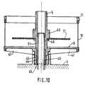
Dans l'exemple représenté sur les figures 9 à 12, l'organe rotatif est constitué par le panier 10 d'une centrifugeuse. Ce panier tourne à l'intérieur d'une cuve (non représentée), dont seul apparaît sur la figure, le fond 2 présentant un orifice central 1, à l'intérieur duquel s'élève l'arbre moteur 3 entouré par une cheminée 4.In the example shown in Figures 9 to 12, the rotary member is constituted by the
Le tamis centrifugeur 10 comporte une jupe formant moyeu 19 d'entraînement en rotation. Sur l'arbre moteur est posé un mandrin 5 dont la partie inférieure pénètre librement à l'intérieur du filetage 43 du moyeu 19. Le mandrin 5 porte lui-même, au-dessus de la jupe 45, un filetage 44. Le mandrin 5 est par ailleurs muni de moyens d'encliquetage 46 constitués par des pattes élastiques et destinés à maintenir le disque râpeur 17.The
Comme connu en soi, le mandrin 5 présente un alésage central 51, dont la partie inférieure peut se terminer par un ou deux pans coupés ou encore présenter une forme polygonale, de manière à ce que l'entraînement du mandrin par l'arbre moteur 3, s'effectue sans glissement. La Jupe 45 présente, avantageusement des moyens d'encliquetage (non représentés) sur l'arbre moteur.As known per se, the
Comme représenté sur la figure 9, le panier 10 présente, à sa partie inférieure, des nervures de rigidité 47. Par ailleurs, la cheminée 4 présente, à sa partie supérieure, des crans 48 (voir figure 12) entre lesquels les nervures 47 du panier 10 peuvent venir prendre appui.As shown in FIG. 9, the
Ainsi, au début des opérations lorsque la ménagère pose le panier 10 à l'intérieur de la cuve de travail, les nervures 47 viennent naturellement porter entre deux créneaux 48, et le panier reste ainsi posé sur l'extrémité supérieure de la cheminée 4. Ensuite la ménagère introduit, à l'intérieur du moyeu 19 du panier 10, le mandrin 5, dont la jupe 45 pénètre a l'intérieur du filetage 43 du moyeu 19 sans être prise avec le filetage 43 et la râpe 17.Thus, at the start of operations when the housewife places the
Le fonctionnement du dispositif est le suivant. A partir de la position représentée sur la figure 9 où les différents éléments sont posés les uns sur les autres, la mise en marche du moteur, par exemple dans le sens inverse des aiguilles d'une montre, provoque, lorsque le pas de filetage 43 du moyeu 19 est dans le même sens, c'est-à-dire à gauche, le vissage du filetage 44 à l'intérieur du filetage 43 du moyeu 19, le panier étant immobilisé en rotation par les créneaux 48. Par suite, le mandrin 5 se visse à l'intérieur du moyeu 19 du panier 10 et descend axialement très rapidement, de sorte que la partie inférieure de la jupe 45 vienne en butée sur l'arbre moteur.The operation of the device is as follows. From the position shown in Figure 9 where the different elements are placed on top of each other, starting of the motor, for example in the anticlockwise direction, causes, when the
Cette position est représentée sur la figure 10. Mais, à partir de ce moment, le mandrin 5 continue de tourner toujours dans le même sens. Il en résulte que le moyeu 19 est à son tour entraîné en rotation dans le même sens et se visse sur le mandrin 5. Ce vissage provoque le soulèvement du panier 10 et le dégagement des nervures 47, hors de la partie crenelée 48 de la jupe 3. Le panier 10 peut alors entrer en rotation et il s'élève le long du mandrin jusqu'à ce que le fond 9 du panier 10 arrive au contact du manchon 49 du mandrin 5. Une rainure circulaire 50 permet la pénétration de la partie centrale du disque 17 et des moyens d'encliquetage 46. Ainsi, le mandrin 5 et le panier 10 tournent à la même vitesse et dans le même sens que l'arbre moteur 3. Cette position est représentée sur la figure 11. Finalement, c'est la hauteur des zones filetées qui fixe le niveau de l'organe rotatif à l'intérieur de la cuve 2.This position is shown in Figure 10. But, from this moment, the
Lorsque le traitement des aliments est terminé, le moteur est arrêté et l'ensemble mandrin 5, panier 10, est extrait de la cuve en vue du nettoyage. Le mandrin peut être aisément séparé du panier 10 par une lègère traction suivie d'un mouvement de rotation.When the food processing is finished, the engine is stopped and the
Bien entendu, il importe que les filetages 43 et 44 soient des filetages rapides afin que les mouvements de descente du mandrin 5, puis de montée du moyeu 19 sur le mandrin 5, se réalisent en une fraction de seconde.Of course, it is important that the
A titre d'exemple seulement, des résultats satisfaisants ont été obtenus avec un moteur tournant à une vitesse de 1500 tours/minute, les filetages 43 et 44 étant des filetages carrés au pas de 10 à gauche dans les deux cas, le filetage étant réduit à deux filets carrés.By way of example only, satisfactory results have been obtained with an engine running at a speed of 1500 revolutions / minute, the
Le dispositif qui vient d'être décrit peut être mis en oeuvre pour tout organe rotatif présentant un moyeu entourant un mandrin amovible.The device which has just been described can be implemented for any rotary member having a hub surrounding a removable mandrel.
Claims (13)
- Apparatus for extracting juice and pulp from vegetable products comprising a stand housing an electric motor, a bowl removably mounted on the stand so that a drive shaft surrounded by a central chimney projects inside the bowl, a lockable lid on said bowl and a vertical strainer whose wall is parallel to the cylindrical wall of the bowl, the strainer comprising a skirt (19) penetrating within the chimney (4), the skirt surrounding but not touching the drive shaft (3), characterized in that a mandrel (5) may be secured to the drive shaft (3) in either of two directions, in one of which the strainer (10) remains stationary and in the other of which the strainer (10) is rotated when the drive shaft (3) rotates, and in that it comprises interchangeable tools (7, 17, 15) which can be selectively mounted on the drive shaft (3) via the mandrel (5).
- Apparatus according to any of claims 1 to 3, characterized in that the base (2) of the bowl (1) is inclined towards a gully (24) for removing the juice.
- Apparatus according to either of claims 1 or 2, characterized in that the mandrel (5) is driven by and snap-fastened on the shaft (3), the mandrel (5) carrying Tugs (6) which co-operate with grooves provided in the hubs of the tools (7, 17, 15).
- Apparatus according to claim 1, characterized in that it comprises two removable lids (12, 13) used respectively when the apparatus functions as a press or centrifuge and when it functions as a fruit-press/centrifuge.
- Apparatus according to any of the preceding claims, characterized in that a seal (11) is located at the top of the strainer, the seal occupying either an upper position in which it is in contact with the inside face of the lid (12) or a lower position in which it is spaced from said face, these positions being a function of the position of the mandrel (5).
- Apparatus according to any of the preceding claims, characterized in that the strainer (10) is stationary, a rotor (7) driven by the shaft (3) and carrying at least one blade (27), the rotor revolving within the strainer (10) so that the edges of its blades extend up to the strainer (10), the seal (11) being in the higher position.
- A rotor for an apparatus according to claim 6, characterized in that the rotor is constituted by two blades (27) connected to a hub (22) by flexible links (23), the edges of the blades (7) being inclined from front to rear and from top to bottom.
- A rotor for an apparatus according to claim 6, characterized in that two blades (27) are freely mounted on the rotor (7) about vertical axes (23) which are eccentric relative to the axis of the rotor, the blades (27) being inclined from top to bottom at an angle in the range 6° to 12° to pick up the matter in the bottom of the strainer.
- Apparatus according to any of claims 1 to 5, characterized in that the strainer (10) is rotated by the mandrel (5), the strainer (1) being integral with a disc (9) supporting a grater (17), the seal (11) being in the lower position, a lining (28) whose lower portion is flush with the upper surface of the grater (17) being engaged inside the chute (10).
- Apparatus according to any of claims 1 to 5, characterized in that a citrus-press cone (15) is mounted on the mandrel (5), the surface (14) of the lid (13) forming a funnel, the strainer (10) being rotated and the seal (11) being in the lower position.
- Apparatus according to claim 1, characterized in that the skirt (19) of the strainer (10) is provided with an internal thread (43) in the same direction as the direction of rotation of the drive shaft, the mandrel (5) having an external thread (44) in the same direction, the external diameter of which corresponds to the internal diameter of the thread (43) on the skirt (19).
- Apparatus according to claim 11, characterized in that the strainer has strengthening ribs (47), the height of the skirt (19) being less than that of the central chimney (4) of the bowl (2) into which the component is inserted, the upper surface of the chimney (4) being provided with notches (48) to prevent the strainer (10) from being rotated before it has been raised.
- Apparatus according to any of claims 1 to 12, characterized in that the mandrel (5) comprises, from bottom to top, a smooth skirt (45), a thread (44) and a sleeve (49).
Priority Applications (1)
| Application Number | Priority Date | Filing Date | Title |
|---|---|---|---|
| AT88902866TATE94358T1 (en) | 1987-12-31 | 1988-03-21 | DEVICE FOR OBTAINING JUICE AND PULP FROM FRUITS AND VEGETABLES. |
Applications Claiming Priority (3)
| Application Number | Priority Date | Filing Date | Title |
|---|---|---|---|
| FR8718475AFR2625426B1 (en) | 1987-12-31 | 1987-12-31 | PRESS TO EXPRESS PLANT JUICE |
| FR8718475 | 1987-12-31 | ||
| US07/401,313US5289763A (en) | 1987-12-31 | 1989-08-31 | Device for the extraction of juice and pulp from fruit and vegetables |
Publications (2)
| Publication Number | Publication Date |
|---|---|
| EP0346392A1 EP0346392A1 (en) | 1989-12-20 |
| EP0346392B1true EP0346392B1 (en) | 1993-09-15 |
Family
ID=26226427
Family Applications (1)
| Application Number | Title | Priority Date | Filing Date |
|---|---|---|---|
| EP88902866AExpired - LifetimeEP0346392B1 (en) | 1987-12-31 | 1988-03-21 | Appliance for extracting juice and pulp from fruit and vegetables |
Country Status (6)
| Country | Link |
|---|---|
| US (1) | US5289763A (en) |
| EP (1) | EP0346392B1 (en) |
| JP (1) | JP3107553B2 (en) |
| DE (1) | DE3884194D1 (en) |
| FR (1) | FR2625426B1 (en) |
| WO (1) | WO1989006106A1 (en) |
Families Citing this family (49)
| Publication number | Priority date | Publication date | Assignee | Title |
|---|---|---|---|---|
| SE464331B (en)* | 1989-08-02 | 1991-04-15 | Swedish Chef Ab | JUICEEXTRAKTIONSAPPARAT |
| US5355784A (en)* | 1991-12-20 | 1994-10-18 | Trillium Health Products, Inc. | Juice extractors |
| US5156084A (en)* | 1992-03-26 | 1992-10-20 | Waying-Hhs Taiwan, Ltd. | Food processor |
| US5222430A (en)* | 1992-08-19 | 1993-06-29 | Johnson Wang | Juicer/mixer device |
| CA2119495A1 (en)* | 1993-03-29 | 1994-09-30 | David N. Anderson | Fruit and vegetable juice extractor |
| US5421248A (en)* | 1994-08-29 | 1995-06-06 | Airlux Electrical Co., Ltd. | Multi-food processor and juice extractor |
| US5435237A (en)* | 1995-02-03 | 1995-07-25 | Huang; Andrew W. H. | Multipurpose food processor |
| US5537918A (en)* | 1995-11-22 | 1996-07-23 | Patel; Chandulal F. | Juice extracting device |
| US5662032A (en)* | 1996-03-15 | 1997-09-02 | Baratta; Joseph P. | Juicer attachment for a blender |
| US6015228A (en)* | 1996-11-26 | 2000-01-18 | Muller; Ernst R. | Dry material and slurry processor |
| US5669289A (en)* | 1996-12-30 | 1997-09-23 | Chen; Tse-Hsiung | Strainer assembly |
| US5819641A (en)* | 1997-03-11 | 1998-10-13 | Hsu; Maxwell | Multifunctional food processing machine |
| WO1999059454A1 (en)* | 1998-05-15 | 1999-11-25 | Koninklijke Philips Electronics N.V. | A kitchen appliance comprising a container with a filter |
| US6668709B1 (en)* | 2000-06-29 | 2003-12-30 | Electrodomesticos Taurus, S.L. | Citrus fruit squeezer with centrifugation of the squeezed product |
| DE10151231C2 (en)* | 2001-10-17 | 2003-08-21 | Maweva Holding Ag Ltd Mettlen | Food processor for food preparation |
| USD471771S1 (en) | 2002-03-14 | 2003-03-18 | Hamilton Beach/Proctor-Silex, Inc. | Juicer |
| US6536335B1 (en)* | 2002-06-04 | 2003-03-25 | Main Power Electrical Factory Ltd. | Juicer and shaver |
| GB2412332A (en)* | 2004-03-25 | 2005-09-28 | Prince Tikare | A combined juice extractor and mixer |
| FR2859617B1 (en)* | 2003-09-17 | 2007-06-08 | Hameur Sa | APPARATUS FOR EXTRACTING JUICE AND PULP OF VEGETABLE PRODUCTS WITH IMPROVED YIELD |
| US7530510B2 (en)* | 2004-03-19 | 2009-05-12 | Hamilton Beach Brands, Inc. | Storage food processor |
| US6981442B1 (en)* | 2004-06-23 | 2006-01-03 | Wei-Chih Lin | Device for adjusting gap between feeding tube and blade disk of food processors |
| US20060065767A1 (en)* | 2004-09-28 | 2006-03-30 | Wei-Chin Lin | Scrap device for removing debris on filter of food processors |
| ITPR20040070A1 (en)* | 2004-10-05 | 2005-01-05 | Ro Snc Di Notari Roberto E Pia | DISTRIBUTION AND TREATMENT SYSTEM FOR PASTRY AND REFINING MACHINES FOR FOOD PRODUCTS. |
| US9016196B2 (en)* | 2005-06-03 | 2015-04-28 | Breville Pty Limited | Compact juicer |
| WO2009006920A1 (en)* | 2007-07-09 | 2009-01-15 | Ab Skf | Bearing arrangement |
| BRPI0821013A8 (en)* | 2007-12-19 | 2015-11-10 | Koninklijke Philips Electronics Nv | CENTRIFIC VESSEL, JUICE SQUEEZER AND METHOD OF IMPROVING THE JUICE OUTLET OF A JUICE SQUEEZER |
| US8807022B2 (en) | 2009-10-12 | 2014-08-19 | Alan Backus | Devices and methods to disintegrate foods |
| IT1399385B1 (en)* | 2010-04-08 | 2013-04-16 | Fedeli | DEVICE FOR THE EXTRACTION OF JUICE AND PULP FROM A FRUIT OR FROM A VEGETABLE |
| EP2974628B1 (en)* | 2010-12-13 | 2017-11-22 | Novis AG | Apparatus for extracting juice and pulp from fruit or vegetables |
| TWD145039S (en) | 2010-12-20 | 2012-01-11 | 寶貝快廚有限責任公司 | Food storage cup |
| TWD147104S (en) | 2010-12-20 | 2012-05-11 | 寶貝快廚有限責任公司 | Kitchen food processor container |
| US9556916B2 (en) | 2013-03-15 | 2017-01-31 | Whirlpool Corporation | High performance adjustable juicer with whole foods feed chute and clutch mechanism |
| US9675101B2 (en) | 2013-03-15 | 2017-06-13 | Whirlpool Corporation | High performance adjustable juicer with whole foods feed chute |
| US10433577B2 (en) | 2013-03-15 | 2019-10-08 | Whirlpool Corporation | High performance adjustable juicer with pulp chute |
| US9095169B1 (en)* | 2013-04-12 | 2015-08-04 | Radius Corporation | Hand operable juicer |
| ITPI20130086A1 (en)* | 2013-09-30 | 2015-03-31 | Alessandro Bertocchi | METHOD FOR PUREE PRODUCTION, OR JUICE, FROM FOOD PRODUCTS AND MACHINE THAT ACTIVES THIS METHOD |
| EP3064074A1 (en)* | 2013-10-31 | 2016-09-07 | Nepuree Corporation | Operation method for strainer |
| AU2015291364B2 (en)* | 2014-07-18 | 2019-10-24 | Pi-Design Ag | Kitchen appliance for processing foodstuff |
| US20170020341A1 (en)* | 2015-07-20 | 2017-01-26 | Duane Farmer | Multi-function kitchen utensil |
| CN105342353A (en)* | 2015-12-01 | 2016-02-24 | 苏州市赛品电器有限公司 | Extrusion juicing spiral sensing structure |
| CN105342350A (en)* | 2015-12-01 | 2016-02-24 | 苏州市赛品电器有限公司 | Efficient squeezing juicing induction structure |
| CN105342348A (en)* | 2015-12-01 | 2016-02-24 | 苏州市赛品电器有限公司 | Efficient squeezing juicing spiral structure |
| CN105342351A (en)* | 2015-12-01 | 2016-02-24 | 苏州市赛品电器有限公司 | Efficient squeezing juicing spiral induction structure |
| CN105342337A (en)* | 2015-12-01 | 2016-02-24 | 苏州市赛品电器有限公司 | Extrusion juicing sensing structure |
| EP3586697A1 (en)* | 2018-06-25 | 2020-01-01 | Koninklijke Philips N.V. | A food preparation apparatus |
| NL2022810B1 (en) | 2019-03-26 | 2020-10-02 | Bravilor Bonamat Bv | Device for extracting juice and pulp from fruit |
| US20230081848A1 (en)* | 2019-12-31 | 2023-03-16 | Ad Maiora S.R.L. | Semi-automatic machine for crushing and for collecting outside frozen food substances for a subsequent food use of said food substances |
| US20220279955A1 (en)* | 2021-03-03 | 2022-09-08 | Capbran Holdings, Llc | Juicer |
| CN219048162U (en)* | 2022-11-08 | 2023-05-23 | 飞利浦家电控股有限公司 | Filtering component and kitchen processor |
Family Cites Families (21)
| Publication number | Priority date | Publication date | Assignee | Title |
|---|---|---|---|---|
| US2101620A (en)* | 1937-12-07 | lewis | ||
| US1697618A (en)* | 1926-06-18 | 1929-01-01 | Strite Anderson Mfg Company | Juice extractor |
| US2297880A (en)* | 1939-01-21 | 1942-10-06 | Jiffy Juicing Machines Inc | Fruit and vegetable juicer |
| US2289656A (en)* | 1940-09-23 | 1942-07-14 | Knapp Monarch Co | Juicer mechanism |
| US2440425A (en)* | 1944-09-23 | 1948-04-27 | Joseph B Williams | Fruit and vegetable juice extractor |
| US2533811A (en)* | 1946-02-01 | 1950-12-12 | Sunbeam Corp | Juice extracting device with vibrating strainer |
| US2481848A (en)* | 1946-10-25 | 1949-09-13 | Lapps Rudolph | Juice extractor |
| US2481010A (en)* | 1948-08-17 | 1949-09-06 | Knapp Monarch Co | Juicer for fruits and vegetables with vertical axis rotating grater plate |
| CH284332A (en)* | 1950-04-15 | 1952-07-31 | Stamm Bruno | Household machine. |
| GB746496A (en)* | 1953-07-20 | 1956-03-14 | Edward Peter Schreyer | Improvements in and relating to juice extractors |
| US2757696A (en)* | 1954-04-02 | 1956-08-07 | Billard Anthony Frederick | Juice extracting machines |
| US3100009A (en)* | 1960-12-30 | 1963-08-06 | Ruth P Drachenberg | Juice extractor having overrunning spinner |
| CH369261A (en)* | 1960-03-23 | 1963-05-15 | Edmund Drachenberg Richard | Juice extractor |
| US3101107A (en)* | 1962-03-26 | 1963-08-20 | Kitchen Master Appliance Inc | Fruit and vegetable juice extractor |
| FR1444849A (en)* | 1965-05-25 | 1966-07-08 | Moulinex Sa | Household chopper |
| FR2129193A6 (en)* | 1971-03-18 | 1972-10-27 | Verdun Pierre | |
| GB1567014A (en)* | 1976-01-22 | 1980-05-08 | In Da Te Ag | Extractors |
| JPS5379076A (en)* | 1976-12-22 | 1978-07-13 | Matsushita Electric Industrial Co Ltd | Juicer |
| FR2459031A1 (en)* | 1979-06-18 | 1981-01-09 | Robot Coupe Sa | PRESS-CITRUS DEVICE FOR KITCHEN ROBOT |
| US4702162A (en)* | 1987-04-14 | 1987-10-27 | Cuisinarts, Inc. | Salad spinner dryer apparatus rotated by speed reducing friction drive for use wih food processors |
| IT1218677B (en)* | 1987-08-26 | 1990-04-19 | Girmi Spa | DEVICE FOR TOMATO PRESS |
- 1987
- 1987-12-31FRFR8718475Apatent/FR2625426B1/ennot_activeExpired - Lifetime
- 1988
- 1988-03-21JPJP63502913Apatent/JP3107553B2/ennot_activeExpired - Fee Related
- 1988-03-21WOPCT/FR1988/000144patent/WO1989006106A1/enactiveIP Right Grant
- 1988-03-21DEDE88902866Tpatent/DE3884194D1/ennot_activeExpired - Lifetime
- 1988-03-21EPEP88902866Apatent/EP0346392B1/ennot_activeExpired - Lifetime
- 1989
- 1989-08-31USUS07/401,313patent/US5289763A/ennot_activeExpired - Lifetime
Also Published As
| Publication number | Publication date |
|---|---|
| FR2625426A1 (en) | 1989-07-07 |
| JP3107553B2 (en) | 2000-11-13 |
| FR2625426B1 (en) | 1992-06-19 |
| US5289763A (en) | 1994-03-01 |
| DE3884194D1 (en) | 1993-10-21 |
| EP0346392A1 (en) | 1989-12-20 |
| JPH02503991A (en) | 1990-11-22 |
| WO1989006106A1 (en) | 1989-07-13 |
Similar Documents
| Publication | Publication Date | Title |
|---|---|---|
| EP0346392B1 (en) | Appliance for extracting juice and pulp from fruit and vegetables | |
| EP2326220B1 (en) | Electrical household appliance for preparing juice | |
| CA2480230C (en) | Apparatus for extracting juice and pulp from vegetable produce with improved performance | |
| CA2404512C (en) | Rotating tool drive unit for food processing apparatus, and food processing apparatus equipped with same | |
| US5537918A (en) | Juice extracting device | |
| FR2834436A3 (en) | Fruit and vegetable juice extractor comprises disc cutter provided at top central area with radial rows of blades arranged in cross form and having end of one central blade extending across center of disc cutter | |
| WO2013041466A1 (en) | Electrical household appliance including a working vessel provided with a filter | |
| FR2617388A1 (en) | APPARATUS FOR GROWING AND PROCESSING FOOD PRODUCTS, SUCH AS FRUIT OR VEGETABLES | |
| FR2938415A1 (en) | Electrical household appliance for preparing fresh juice from e.g. oranges, has filtration unit mounted with pressing screw inside work chamber, and outlet connected to work chamber by pipe for discharging pressing residues by gravity | |
| FR2540372A3 (en) | HOUSEHOLD APPLIANCE FOR THE PROCESSING OF FOOD PRODUCTS | |
| EP3429378B1 (en) | Membrane citrus press | |
| WO2020178386A1 (en) | Device for extracting juice from fruits and/or vegetables | |
| EP0021974B1 (en) | Citrus fruit press for a kitchen appliance | |
| EP1949803B1 (en) | Device for extracting juice and pulp from vegetable products by forced insertion and associated screen | |
| EP2120612B1 (en) | Citrus squeezer for squeezing a whole citrus | |
| EP2606778B1 (en) | Elektrohaushaltsgerät zur Getränkezubereitung, das mit einem Arbeitsbehälter und einer Filtervorrichtung ausgestattet ist | |
| EP3429436B1 (en) | Device for pressing foodstuffs equipped with a drum storage system | |
| FR2912632A1 (en) | Automatic/semi-automatic type press for orange, has separator units integrated to blades and arranged between blades and cone so that dome is movable, and ejection unit driven in rotation along direction opposite to that of cone | |
| FR2608032A1 (en) | Apparatus for extracting juices from fruit and vegetables | |
| FR2545712A3 (en) | Electrical household appliance for processing foodstuffs | |
| WO2023031292A1 (en) | Food preparation appliance, tool and cover of such an appliance | |
| FR2912631A1 (en) | Automatic or semi-automatic press for citrus fruit i.e. orange, has pressing dome moving with respect to blades and pressing cone and including support wall that has perforations communicating with reservoir arranged on top of dome | |
| FR2859616A1 (en) | Plant product e.g. pineapple, juice and pulp extracting apparatus, has cylindrical sieve including opening for introducing plant products in sieve, and immovable blade extending inside sieve near radial wall of sieve | |
| CH333127A (en) | Fruit and vegetable juice extractor | |
| BE667006A (en) |
Legal Events
| Date | Code | Title | Description |
|---|---|---|---|
| PUAI | Public reference made under article 153(3) epc to a published international application that has entered the european phase | Free format text:ORIGINAL CODE: 0009012 | |
| AK | Designated contracting states | Kind code of ref document:A1 Designated state(s):AT BE CH DE FR GB IT LI LU NL SE | |
| 17P | Request for examination filed | Effective date:19900108 | |
| 17Q | First examination report despatched | Effective date:19920304 | |
| GRAA | (expected) grant | Free format text:ORIGINAL CODE: 0009210 | |
| AK | Designated contracting states | Kind code of ref document:B1 Designated state(s):AT BE CH DE FR GB IT LI LU NL SE | |
| PG25 | Lapsed in a contracting state [announced via postgrant information from national office to epo] | Ref country code:AT Effective date:19930915 Ref country code:IT Free format text:LAPSE BECAUSE OF FAILURE TO SUBMIT A TRANSLATION OF THE DESCRIPTION OR TO PAY THE FEE WITHIN THE PRESCRIBED TIME-LIMIT;WARNING: LAPSES OF ITALIAN PATENTS WITH EFFECTIVE DATE BEFORE 2007 MAY HAVE OCCURRED AT ANY TIME BEFORE 2007. THE CORRECT EFFECTIVE DATE MAY BE DIFFERENT FROM THE ONE RECORDED. Effective date:19930915 Ref country code:NL Effective date:19930915 Ref country code:SE Effective date:19930915 Ref country code:GB Effective date:19930915 Ref country code:DE Effective date:19930915 | |
| REF | Corresponds to: | Ref document number:94358 Country of ref document:AT Date of ref document:19931015 Kind code of ref document:T | |
| REF | Corresponds to: | Ref document number:3884194 Country of ref document:DE Date of ref document:19931021 | |
| NLV1 | Nl: lapsed or annulled due to failure to fulfill the requirements of art. 29p and 29m of the patents act | ||
| GBV | Gb: ep patent (uk) treated as always having been void in accordance with gb section 77(7)/1977 [no translation filed] | Effective date:19930915 | |
| PG25 | Lapsed in a contracting state [announced via postgrant information from national office to epo] | Ref country code:LI Effective date:19940331 Ref country code:LU Free format text:LAPSE BECAUSE OF NON-PAYMENT OF DUE FEES Effective date:19940331 Ref country code:CH Effective date:19940331 Ref country code:BE Effective date:19940331 | |
| PLBE | No opposition filed within time limit | Free format text:ORIGINAL CODE: 0009261 | |
| STAA | Information on the status of an ep patent application or granted ep patent | Free format text:STATUS: NO OPPOSITION FILED WITHIN TIME LIMIT | |
| 26N | No opposition filed | ||
| BERE | Be: lapsed | Owner name:S.A. ROBOT-COUPE Effective date:19940331 | |
| REG | Reference to a national code | Ref country code:CH Ref legal event code:PL | |
| PGFP | Annual fee paid to national office [announced via postgrant information from national office to epo] | Ref country code:FR Payment date:20070202 Year of fee payment:20 |