EP0346089B1 - Reception system - Google Patents
Reception systemDownload PDFInfo
- Publication number
- EP0346089B1 EP0346089B1EP89305733AEP89305733AEP0346089B1EP 0346089 B1EP0346089 B1EP 0346089B1EP 89305733 AEP89305733 AEP 89305733AEP 89305733 AEP89305733 AEP 89305733AEP 0346089 B1EP0346089 B1EP 0346089B1
- Authority
- EP
- European Patent Office
- Prior art keywords
- reception
- coil
- circuit
- frequency
- antenna
- Prior art date
- Legal status (The legal status is an assumption and is not a legal conclusion. Google has not performed a legal analysis and makes no representation as to the accuracy of the status listed.)
- Expired - Lifetime
Links
- 239000003990capacitorSubstances0.000claimsdescription16
- 230000035699permeabilityEffects0.000claimsdescription5
- 239000005357flat glassSubstances0.000description13
- 238000010586diagramMethods0.000description11
- 230000035945sensitivityEffects0.000description9
- 239000011162core materialSubstances0.000description8
- 230000003247decreasing effectEffects0.000description5
- 239000004020conductorSubstances0.000description4
- 238000010438heat treatmentMethods0.000description4
- 230000006698inductionEffects0.000description3
- 239000011521glassSubstances0.000description2
- 230000004048modificationEffects0.000description2
- 238000012986modificationMethods0.000description2
- 230000009467reductionEffects0.000description2
- 230000008878couplingEffects0.000description1
- 238000010168coupling processMethods0.000description1
- 238000005859coupling reactionMethods0.000description1
- 230000004907fluxEffects0.000description1
- 238000004804windingMethods0.000description1
Images


Classifications
- H—ELECTRICITY
- H03—ELECTRONIC CIRCUITRY
- H03H—IMPEDANCE NETWORKS, e.g. RESONANT CIRCUITS; RESONATORS
- H03H3/00—Apparatus or processes specially adapted for the manufacture of impedance networks, resonating circuits, resonators
- H—ELECTRICITY
- H01—ELECTRIC ELEMENTS
- H01Q—ANTENNAS, i.e. RADIO AERIALS
- H01Q1/00—Details of, or arrangements associated with, antennas
- H01Q1/12—Supports; Mounting means
- H01Q1/1271—Supports; Mounting means for mounting on windscreens
- H01Q1/1278—Supports; Mounting means for mounting on windscreens in association with heating wires or layers
Definitions
- the present inventionrelates to a reception system for a motor vehicle and, more particularly, to a system using an antenna circuit having a large ground stray capacitance.
- a defogging heater conductoris attached to a window glass, particularly to a rear window glass of a vehicle by baking or embedding.
- the heater conductoris used as an antenna or a portion of an antenna element for an AM broadcast band.
- Fig. 8is a view showing a conductor pattern of a window glass antenna of this type.
- a large number of heater wires 2are attached to a defogging region of a rear window glass 1, and power is fed through feeder buses 3 and 4 connected to one end of upper and lower groups of the heater wires and is returned through a junction bus 5 connected to the other end thereof.
- a feeder 7such as a coaxial cable is connected to a feed point 6 of the junction bus 5, and a reception signal is output to a tuner through a DC cut capacitor 8.
- the choke coil 11a connected to a main power supply +B and the choke coil 11b connected to the ground pointare negatively coupled, so that magnetic flux due to the corresponding heating currents cancel each other in the cores, and small-volume cores can be used for operation in a nonsaturated state.
- the choke coils 11a and 11bexhibit high impedances. Since a reception signal induced in the heater wires 2 is prevented from leaking to a low-impedance power supply or ground, reception efficiency is improved.
- a line connected to the main power supply +Bis connected to a decoupling capacitor 14, so that power supply noise is not mixed in the reception signal.
- Fig. 9is an equivalent circuit diagram of the antenna shown in Fig. 8.
- Reference symbol e0denotes an induction electromotive force of the heater wires 2; C1, an active capacitance of the antenna; C2, a reactive capacitance of the antenna; C3, a stray capacitance (reactive capacitance) of the feeders 12 and 13, the feeder cable 7, and the like; Cc, a capacitance of the capacitor 8; R, an internal resistance of the antenna; and Lx, an inductance of the heater wire 2 and the choke coils 11a and 11b.
- the magnitude of the induction electromotive force e0depends on the size of the rear window glass 1.
- the induction electromotive force e0is small.
- the reactive capacitances C2 and C3 in the equivalent circuit diagram shown in Fig. 9are not decreased in proportion as the window glass area is decreased. For this reason, when the window glass area is small, a signal loss due to the reactive capacitances C2 and C3 is relatively increased. Accordingly, when a glass antenna with a small reception area is used, an AM broadcast signal cannot be received well.
- a reception system for a motor vehiclehaving an antenna circuit including an antenna element for supplying a reception signal to a receiver via a matching circuit
- said matching circuitcomprises first and third coils connecting the antenna circuit to ground and constituting a first parallel resonant circuit together with a ground stray capacitance thereof at a frequency set in a reception band, said first coil being series-connected to said third coil and said third coil including a core member having its permeability being set to decrease between lower and higher ends of said reception band with increase of frequency so that the resonance frequency of said parallel resonance circuit increases as a reception frequency increases; and matching means including a second coil associated with said parallel resonant circuit to compensate for a Q-factor thereof so that reception gain is improved over a wide range of reception frequencies.
- An impedance of the antenna circuitis increased in a reception band by parallel resonance, and a signal loss due to the ground stray capacitance can be reduced.
- the matching meanscompensates for Q-factor of the parallel resonance circuit increasing too much and makes the antenna circuit match with the receiver. Reception sensitivity is improved over a wide range in a reception band.
- Fig. 1is a diagram of a rear window glass antenna for a vehicle according to an embodiment of the invention.
- Fig. 2is a circuit diagram of a matching circuit in Fig. 1.
- the conductor pattern of the rear window glass 1 and a supply circuit of heating currentsare the same as those in Fig. 8.
- a reception signal of heater wires 2 derived from a feed point 6is supplied to a matching circuit 30, and an output from the matching circuit 30 is supplied to an input terminal 21a of a tuner 21 through a 3- to 4-m long feeder cable 7.
- a capacitor Cc and a coil L2are connected in series with input and output terminals 30a and 30b of the matching circuit 30.
- the output side of the coil L2is grounded through a series circuit of coils L1 and L3.
- the capacitor Ccis a coupling capacitor (having a capacitance of, e.g., 1,000 pF) for extracting reception power induced in the heater wires 2.
- a reception signal whose DC component is cut by the capacitor Ccis input to the coil L1.
- the coil L2is provided to improve reception sensitivity in a high-frequency range of the AM broadcast band.
- the coil L2 and a reactive capacitance Cfconstitute a low-pass filter to be described later.
- the reactive capacitance Cf between the output terminal 30b and groundrepresents a ground stray capacitance of the feeder cable 7.
- a capacitor C5 connected in parallel with the coil L2is a bypass capacitor (having a capacitance of, e.g., 68 pF) for allowing a reception signal in the FM broadcast band to pass with a small loss, and is connected when the heater wires 2 (antenna) are used for both AM and FM broadcast signals.
- a bypass capacitorhaving a capacitance of, e.g., 68 pF
- the series circuit of the coils L1 and L3 and the reactive capacitance Cfconstitute a first parallel resonance circuit 31.
- the parallel resonance circuit 31is parallel-resonated, a reactive component can be cancelled to improve power reception efficiency.
- the reactive capacitance Cfis about 120 pF.
- the inductance of the coil L2is 180 ⁇ H
- the inductance of the coil L3is 140 ⁇ H as a nominal value.
- the inductance of the coil L3has frequency characteristics, as will be described later.
- the coil L3 connected in series with the coil L1is provided with inductance-frequency characteristics shown in Fig. 5. More specifically, in a low frequency range up to 200 kHz, the inductance is substantially constant, i.e., about 140 ⁇ H, and in a frequency range higher than 200 kHz, the inductance is steeply decreased as the frequency is increased. In an AM reception band between points o and x, the inductance is 95 ⁇ H at 500 kHz, and is 10 ⁇ H at 1,500 kHz.
- a total inductance L1 + L3 of the first parallel resonance circuit 31is decreased from 275 ⁇ H to 190 ⁇ H in a reception band from 500 kHz to 1,500 kHz. For this reason, a resonant point of the first parallel resonance circuit 31 is shifted toward a high-frequency range along with an increase in frequency of a reception signal. Therefore, the first resonance circuit 31 can have wider-range frequency characteristics.
- a capacitor C6is connected in parallel with the coil L3 to constitute a second resonance circuit 32.
- the capacitance of the capacitor C6is adjusted in correspondence with the reactive capacitance Cf, and the second parallel resonance circuit 32 is resonated near 800 kHz in a low-frequency range.
- the first parallel resonance circuit 31is parallel-resonated in middle- and high-frequency ranges of the reception band
- the second parallel resonance circuit 32is parallel-resonated in a low-frequency range of the reception band.
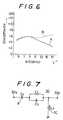
- a characteristic curve A of the reception sensitivity graph of Fig. 6good reception performance can be obtained over a very wide range.
- the characteristics Aare obtained when a series coil L2 to be described below is omitted.
- the coil L2 for forming the low-pass filter 33 together with the reactive capacitance Cfis arranged. If the inductance of the coil L2 is about 47 ⁇ H, it causes a kind of resonance at about 2 MHz with the reactive capacitance Cf of 120 pF. As indicated by a characteristic curve B indicated by a broken curve B in Fig. 6, sensitivity in middle- and high-frequency ranges of the reception band is improved.
- the matching circuit 30 in Fig. 1is inserted at an end of the feeder cable 7 on the side of window glass 1.
- the matching circuit 30may be inserted at another end of the feeder cable 7 on the side of the tuner 21.
- Antenna and the matching circuit 30are coupled through the feeder cable 7.
- the reactive capacitancemay consist of a stray capacitance to ground for the glass antenna comprising the heater wires 2 and a stray capacitance to ground for the cable 7, both coupled in parallel.
- the matching circuit 30may be incorporated in the tuner 21.
- the capacitor C5 for bypassing an FM reception signalcan be omitted when the matching circuit 30 is arranged in an AM tuner.
- Fig. 7is a modification of the matching circuit 30 in which the coil L1 is removed by preferably adjusting the inductance value of coil L3 and permeability of a toroidal core for the coil L3.
- a similar function as that for Fig. 2is effective for this arrangement.
- a core material having permeability ⁇ as large as 2,500 to 8,000may be applied to the coil L3 in the case where a 3- to 4-m long feeder cable 7 having a reactive capacitance Cf of about 120 pF is used.
- the coil L3is wound on the core to have an inductance of 850 ⁇ H at 500 kHz and 75 ⁇ H at 1,700 kHz.
- a series coil L2 and a capacitor C5 in parallel therewithmay be provided if required.
- a resonance coil whose inductance is decreased along with an increase in reception frequencyis arranged in parallel with a ground stray capacitance valued at an input terminal of a tuner on an antenna side, and is parallel-resonated in a reception band. For this reason, if a constant inductance which is parallel-resonated with the reactive capacitance is merely employed, Q is too high and a band is narrow.
- the resonance frequencychanges in correspondence with a reception frequency, and a reduction in gain due to ground stray capacitance can be compensated for over a wide range. Therefore, reception sensitivity of an antenna circuit having a large reactive capacitance can be improved over the entire reception band.
Landscapes
- Engineering & Computer Science (AREA)
- Manufacturing & Machinery (AREA)
- Details Of Aerials (AREA)
Description
- The present invention relates to a reception system for a motor vehicle and, more particularly, to a system using an antenna circuit having a large ground stray capacitance.
- A defogging heater conductor is attached to a window glass, particularly to a rear window glass of a vehicle by baking or embedding. As is well known, the heater conductor is used as an antenna or a portion of an antenna element for an AM broadcast band.
- Fig. 8 is a view showing a conductor pattern of a window glass antenna of this type. A large number of
heater wires 2 are attached to a defogging region of a rear window glass 1, and power is fed throughfeeder buses junction bus 5 connected to the other end thereof. When theheater wires 2 are used as an AM broadcast reception antenna, afeeder 7 such as a coaxial cable is connected to afeed point 6 of thejunction bus 5, and a reception signal is output to a tuner through aDC cut capacitor 8. - Heating currents flow in
feeder buses choke coils feeders choke coil 11a connected to a main power supply +B and thechoke coil 11b connected to the ground point are negatively coupled, so that magnetic flux due to the corresponding heating currents cancel each other in the cores, and small-volume cores can be used for operation in a nonsaturated state. For a received high frequency wave, thechoke coils heater wires 2 is prevented from leaking to a low-impedance power supply or ground, reception efficiency is improved. Note that a line connected to the main power supply +B is connected to adecoupling capacitor 14, so that power supply noise is not mixed in the reception signal. - Fig. 9 is an equivalent circuit diagram of the antenna shown in Fig. 8. Reference symbol e0 denotes an induction electromotive force of the
heater wires 2; C1, an active capacitance of the antenna; C2, a reactive capacitance of the antenna; C3, a stray capacitance (reactive capacitance) of thefeeders feeder cable 7, and the like; Cc, a capacitance of thecapacitor 8; R, an internal resistance of the antenna; and Lx, an inductance of theheater wire 2 and thechoke coils - When an AM broadcast signal is received by the
heater wires 2, the magnitude of the induction electromotive force e0 depends on the size of the rear window glass 1. When the window glass area is small, the induction electromotive force e0 is small. - However, the reactive capacitances C2 and C3 in the equivalent circuit diagram shown in Fig. 9 are not decreased in proportion as the window glass area is decreased. For this reason, when the window glass area is small, a signal loss due to the reactive capacitances C2 and C3 is relatively increased. Accordingly, when a glass antenna with a small reception area is used, an AM broadcast signal cannot be received well.
- Two additional examples of such a reception system, using a motor vehicle window defogging heater and including an antenna element for supplying a reception signal to a receiver via a matching circuit, are disclosed in published European patent applications EP-A-0269924 (Harada) and EP-A-0146339 (BSH). In the Harada system, separate compensation circuits are provided for AM and FM signals, with respective air-core type band-pass filter coils being provided between the battery and heating wires. In the BSH system, various configurations of matching circuit based on choke coils in the heater element current supply lines are disclosed providing series or parallel resonance, or resonance in two pass-bands, near the centre of the VHF band.
- It is a primary object of the invention to compensate for a reduction in gain due to reactive capacitances and to improve a reception sensitivity over a wide range.
- In accordance with the present invention there is provided a reception system for a motor vehicle having an antenna circuit including an antenna element for supplying a reception signal to a receiver via a matching circuit, characterized in that said matching circuit comprises first and third coils connecting the antenna circuit to ground and constituting a first parallel resonant circuit together with a ground stray capacitance thereof at a frequency set in a reception band, said first coil being series-connected to said third coil and said third coil including a core member having its permeability being set to decrease between lower and higher ends of said reception band with increase of frequency so that the resonance frequency of said parallel resonance circuit increases as a reception frequency increases; and matching means including a second coil associated with said parallel resonant circuit to compensate for a Q-factor thereof so that reception gain is improved over a wide range of reception frequencies.
- An impedance of the antenna circuit is increased in a reception band by parallel resonance, and a signal loss due to the ground stray capacitance can be reduced. The matching means compensates for Q-factor of the parallel resonance circuit increasing too much and makes the antenna circuit match with the receiver. Reception sensitivity is improved over a wide range in a reception band.
- These and other objects, features, and advantages of the invention will become more apparent upon a reading of the following detailed specification and drawings in which:
- Fig. 1 is a diagram of a rear window glass antenna for a vehicle to which an embodiment of the present invention is applied;
- Fig. 2 is a circuit diagram of a matching circuit in Fig. 1;
- Fig. 3 is a circuit diagram of a single parallel resonance circuit found in the prior art;
- Fig. 4 is a graph showing reception sensitivity-frequency characteristics when the parallel resonance circuit shown in Fig. 3 is used;
- Fig. 5 is a graph showing inductance-frequency characteristics of a coil used in the embodiment shown in Fig. 2;
- Fig. 6 is a graph showing reception sensitivity-frequency characteristics obtained when the matching circuit shown in Fig. 2 is used;
- Fig. 7 is a circuit diagram of a modification of the matching circuit which is inserted after a feeder cable;
- Fig. 8 is a diagram of a conventional window glass antenna; and
- Fig. 9 is an equivalent circuit diagram of Fig. 8.
- Fig. 1 is a diagram of a rear window glass antenna for a vehicle according to an embodiment of the invention. Fig. 2 is a circuit diagram of a matching circuit in Fig. 1. The conductor pattern of the rear window glass 1 and a supply circuit of heating currents are the same as those in Fig. 8. In this embodiment, a reception signal of
heater wires 2 derived from afeed point 6 is supplied to amatching circuit 30, and an output from the matchingcircuit 30 is supplied to aninput terminal 21a of atuner 21 through a 3- to 4-mlong feeder cable 7. - As shown in Fig. 2, a capacitor Cc and a coil L2 are connected in series with input and
output terminals matching circuit 30. The output side of the coil L2 is grounded through a series circuit of coils L1 and L3. - The capacitor Cc is a coupling capacitor (having a capacitance of, e.g., 1,000 pF) for extracting reception power induced in the
heater wires 2. A reception signal whose DC component is cut by the capacitor Cc is input to the coil L1. The coil L2 is provided to improve reception sensitivity in a high-frequency range of the AM broadcast band. The coil L2 and a reactive capacitance Cf constitute a low-pass filter to be described later. The reactive capacitance Cf between theoutput terminal 30b and ground represents a ground stray capacitance of thefeeder cable 7. A capacitor C5 connected in parallel with the coil L2 is a bypass capacitor (having a capacitance of, e.g., 68 pF) for allowing a reception signal in the FM broadcast band to pass with a small loss, and is connected when the heater wires 2 (antenna) are used for both AM and FM broadcast signals. - The series circuit of the coils L1 and L3 and the reactive capacitance Cf constitute a first
parallel resonance circuit 31. When theparallel resonance circuit 31 is parallel-resonated, a reactive component can be cancelled to improve power reception efficiency. When a 4-mlong feeder cable 7 having a distributed capacitance of 30 pF/m is used, the reactive capacitance Cf is about 120 pF. In this case, the inductance of the coil L2 is 180 µH, and the inductance of the coil L3 is 140 µH as a nominal value. The inductance of the coil L3 has frequency characteristics, as will be described later. - As shown in a prior art circuit diagram of Fig. 3, when only the coil L1 of the fixed inductance is connected in parallel with the reactive capacitance Cf, the reception band becomes very narrow, and sensitive in a range of 800 to 1,300 kHz, as shown in the frequency characteristic graph of reception sensitivity in Fig. 4.
- In order to obtain wide-range reception characteristics, the coil L3 connected in series with the coil L1 is provided with inductance-frequency characteristics shown in Fig. 5. More specifically, in a low frequency range up to 200 kHz, the inductance is substantially constant, i.e., about 140 µH, and in a frequency range higher than 200 kHz, the inductance is steeply decreased as the frequency is increased. In an AM reception band between points o and x, the inductance is 95 µH at 500 kHz, and is 10 µH at 1,500 kHz.
- The coil L3 is formed by winding a wire having a diameter of 0.4 mm seven turns around a toroidal core TC having a high permeability (µ = 5,000).
- Therefore, a total inductance L1 + L3 of the first
parallel resonance circuit 31 is decreased from 275 µH to 190 µH in a reception band from 500 kHz to 1,500 kHz. For this reason, a resonant point of the firstparallel resonance circuit 31 is shifted toward a high-frequency range along with an increase in frequency of a reception signal. Therefore, thefirst resonance circuit 31 can have wider-range frequency characteristics. - Furthermore, in order to improve reception sensitivity in a low-frequency range, a capacitor C6 is connected in parallel with the coil L3 to constitute a
second resonance circuit 32. The capacitance of the capacitor C6 is adjusted in correspondence with the reactive capacitance Cf, and the secondparallel resonance circuit 32 is resonated near 800 kHz in a low-frequency range. The capacitance of the capacitor C6 is set to be about 280 pF when the reactive capacitance Cf = 120 pF. - As described above, the first
parallel resonance circuit 31 is parallel-resonated in middle- and high-frequency ranges of the reception band, and the secondparallel resonance circuit 32 is parallel-resonated in a low-frequency range of the reception band. As a result, as indicated by a characteristic curve A of the reception sensitivity graph of Fig. 6, good reception performance can be obtained over a very wide range. The characteristics A are obtained when a series coil L2 to be described below is omitted. - In order to further improve reception sensitivity in a high-frequency range, the coil L2 for forming the low-
pass filter 33 together with the reactive capacitance Cf is arranged. If the inductance of the coil L2 is about 47 µH, it causes a kind of resonance at about 2 MHz with the reactive capacitance Cf of 120 pF. As indicated by a characteristic curve B indicated by a broken curve B in Fig. 6, sensitivity in middle- and high-frequency ranges of the reception band is improved. - The matching
circuit 30 in Fig. 1 is inserted at an end of thefeeder cable 7 on the side of window glass 1. The matchingcircuit 30 may be inserted at another end of thefeeder cable 7 on the side of thetuner 21. Antenna and thematching circuit 30 are coupled through thefeeder cable 7. In this arrangement, the reactive capacitance may consist of a stray capacitance to ground for the glass antenna comprising theheater wires 2 and a stray capacitance to ground for thecable 7, both coupled in parallel. - The matching
circuit 30 may be incorporated in thetuner 21. The capacitor C5 for bypassing an FM reception signal can be omitted when the matchingcircuit 30 is arranged in an AM tuner. - Fig. 7 is a modification of the matching
circuit 30 in which the coil L1 is removed by preferably adjusting the inductance value of coil L3 and permeability of a toroidal core for the coil L3. A similar function as that for Fig. 2 is effective for this arrangement. For example, a core material having permeability µ as large as 2,500 to 8,000 may be applied to the coil L3 in the case where a 3- to 4-mlong feeder cable 7 having a reactive capacitance Cf of about 120 pF is used. The coil L3 is wound on the core to have an inductance of 850 µH at 500 kHz and 75 µH at 1,700 kHz. A series coil L2 and a capacitor C5 in parallel therewith may be provided if required. - According to the embodiment as described above, a resonance coil whose inductance is decreased along with an increase in reception frequency is arranged in parallel with a ground stray capacitance valued at an input terminal of a tuner on an antenna side, and is parallel-resonated in a reception band. For this reason, if a constant inductance which is parallel-resonated with the reactive capacitance is merely employed, Q is too high and a band is narrow. However, when the inductance is provided with frequency characteristics in a reception band, the resonance frequency changes in correspondence with a reception frequency, and a reduction in gain due to ground stray capacitance can be compensated for over a wide range. Therefore, reception sensitivity of an antenna circuit having a large reactive capacitance can be improved over the entire reception band.
Claims (4)
- A reception system for a motor vehicle having an antenna circuit including an antenna element (2) for supplying a reception signal to a receiver (21) via a matching circuit (30), characterized in that said matching circuit comprises:
first and third coils (L1, L3) connecting the antenna circuit (2, 6, 7, 8) to ground and constituting a first parallel resonant circuit (31) together with a ground stray capacitance (Cf) thereof at a frequency set in a reception band,
said first coil (L1) being series-connected to said third coil (L3) and
said third coil (L3) including a core member (TC) having its permeability being set to decrease between lower and higher ends of said reception band with increase of frequency so that the resonance frequency of said parallel resonance circuit increases as a reception frequency increases; and
matching means including a second coil (L2) associated with said parallel resonant circuit to compensate for a Q-factor thereof so that reception gain is improved over a wide range of reception frequencies. - A reception system according to claim 1, wherein said parallel resonant circuit (31) and said matching means operate effectively in an AM broadcast band and a capacitor (C5) is parallel connected to said second coil (L2) for FM reception signal to bypass the coil.
- A reception system according to claim 1, wherein said antenna circuit comprises a feeder cable (7) connected between said antenna element (2) and said receiver (21), said first coil (L1) being connected to said feeder cable (7) on the side of said antenna element (2), said second coil (L2) connecting said antenna element (2) to said feeder cable (7) and said ground stray capacitance (Cf) being that of said feeder cable.
- A reception system according to claim 1, wherein said parallel resonant circuit (31) includes a capacitor (C₆) paralleled to said third coil (L3), so as to be set to resonate at the frequency on the lower side of the reception band.
Applications Claiming Priority (4)
| Application Number | Priority Date | Filing Date | Title |
|---|---|---|---|
| JP1988077190UJPH057789Y2 (en) | 1988-06-10 | 1988-06-10 | |
| JP1988077189UJPH0453070Y2 (en) | 1988-06-10 | 1988-06-10 | |
| JP77189/88 | 1988-06-10 | ||
| JP77190/88 | 1988-06-10 |
Publications (2)
| Publication Number | Publication Date |
|---|---|
| EP0346089A1 EP0346089A1 (en) | 1989-12-13 |
| EP0346089B1true EP0346089B1 (en) | 1993-09-29 |
Family
ID=26418296
Family Applications (1)
| Application Number | Title | Priority Date | Filing Date |
|---|---|---|---|
| EP89305733AExpired - LifetimeEP0346089B1 (en) | 1988-06-10 | 1989-06-07 | Reception system |
Country Status (4)
| Country | Link |
|---|---|
| EP (1) | EP0346089B1 (en) |
| KR (1) | KR900001119A (en) |
| DE (1) | DE68909498T2 (en) |
| ES (1) | ES2044118T3 (en) |
Cited By (14)
| Publication number | Priority date | Publication date | Assignee | Title |
|---|---|---|---|---|
| US7071776B2 (en) | 2001-10-22 | 2006-07-04 | Kyocera Wireless Corp. | Systems and methods for controlling output power in a communication device |
| US7116954B2 (en) | 2001-04-11 | 2006-10-03 | Kyocera Wireless Corp. | Tunable bandpass filter and method thereof |
| US7154440B2 (en) | 2001-04-11 | 2006-12-26 | Kyocera Wireless Corp. | Phase array antenna using a constant-gain phase shifter |
| US7164329B2 (en) | 2001-04-11 | 2007-01-16 | Kyocera Wireless Corp. | Tunable phase shifer with a control signal generator responsive to DC offset in a mixed signal |
| US7174147B2 (en) | 2001-04-11 | 2007-02-06 | Kyocera Wireless Corp. | Bandpass filter with tunable resonator |
| US7176845B2 (en) | 2002-02-12 | 2007-02-13 | Kyocera Wireless Corp. | System and method for impedance matching an antenna to sub-bands in a communication band |
| US7180467B2 (en) | 2002-02-12 | 2007-02-20 | Kyocera Wireless Corp. | System and method for dual-band antenna matching |
| US7184727B2 (en) | 2002-02-12 | 2007-02-27 | Kyocera Wireless Corp. | Full-duplex antenna system and method |
| US7221243B2 (en) | 2001-04-11 | 2007-05-22 | Kyocera Wireless Corp. | Apparatus and method for combining electrical signals |
| US7248845B2 (en) | 2004-07-09 | 2007-07-24 | Kyocera Wireless Corp. | Variable-loss transmitter and method of operation |
| US7394430B2 (en) | 2001-04-11 | 2008-07-01 | Kyocera Wireless Corp. | Wireless device reconfigurable radiation desensitivity bracket systems and methods |
| US7548762B2 (en) | 2005-11-30 | 2009-06-16 | Kyocera Corporation | Method for tuning a GPS antenna matching network |
| US7720443B2 (en) | 2003-06-02 | 2010-05-18 | Kyocera Wireless Corp. | System and method for filtering time division multiple access telephone communications |
| US7746292B2 (en) | 2001-04-11 | 2010-06-29 | Kyocera Wireless Corp. | Reconfigurable radiation desensitivity bracket systems and methods |
Families Citing this family (6)
| Publication number | Priority date | Publication date | Assignee | Title |
|---|---|---|---|---|
| DE4312259C2 (en)* | 1993-04-15 | 1997-04-30 | Flachglas Ag | Motor vehicle antenna with AM antenna |
| DE19536131C2 (en)* | 1995-09-28 | 2002-05-02 | Saint Gobain Sekurit D Gmbh | Diversity antenna disc for vehicles with connection elements |
| GB9604951D0 (en)* | 1996-03-08 | 1996-05-08 | Glass Antennas Tech Ltd | Antenna arrangement |
| US5874926A (en)* | 1996-03-11 | 1999-02-23 | Murata Mfg Co. Ltd | Matching circuit and antenna apparatus |
| WO2002084788A1 (en)* | 2001-04-11 | 2002-10-24 | Kyocera Wireless Corporation | Tunable antenna matching circuit |
| KR100838233B1 (en)* | 2006-07-04 | 2008-06-17 | 아마티스(주) | Car Film Antenna Unit |
Family Cites Families (4)
| Publication number | Priority date | Publication date | Assignee | Title |
|---|---|---|---|---|
| DE3479772D1 (en)* | 1983-12-20 | 1989-10-19 | Bsh Electronics Ltd | Electrical signal separating device having isolating and matching circuitry |
| DE3409876A1 (en)* | 1984-03-17 | 1985-09-19 | Robert Bosch Gmbh, 7000 Stuttgart | Heated-window antenna |
| GB2187042A (en)* | 1986-02-21 | 1987-08-26 | Plessey Co Plc | Impedance matching circuit for an aerial |
| JPS63131704A (en)* | 1986-11-21 | 1988-06-03 | Harada Kogyo Kk | Glass antenna compensation amplifier |
- 1989
- 1989-06-07EPEP89305733Apatent/EP0346089B1/ennot_activeExpired - Lifetime
- 1989-06-07ESES89305733Tpatent/ES2044118T3/ennot_activeExpired - Lifetime
- 1989-06-07DEDE89305733Tpatent/DE68909498T2/ennot_activeExpired - Fee Related
- 1989-06-09KRKR1019890007956Apatent/KR900001119A/ennot_activeWithdrawn
Cited By (19)
| Publication number | Priority date | Publication date | Assignee | Title |
|---|---|---|---|---|
| US7221327B2 (en) | 2001-04-11 | 2007-05-22 | Kyocera Wireless Corp. | Tunable matching circuit |
| US7394430B2 (en) | 2001-04-11 | 2008-07-01 | Kyocera Wireless Corp. | Wireless device reconfigurable radiation desensitivity bracket systems and methods |
| US7154440B2 (en) | 2001-04-11 | 2006-12-26 | Kyocera Wireless Corp. | Phase array antenna using a constant-gain phase shifter |
| US7221243B2 (en) | 2001-04-11 | 2007-05-22 | Kyocera Wireless Corp. | Apparatus and method for combining electrical signals |
| US7174147B2 (en) | 2001-04-11 | 2007-02-06 | Kyocera Wireless Corp. | Bandpass filter with tunable resonator |
| US8237620B2 (en) | 2001-04-11 | 2012-08-07 | Kyocera Corporation | Reconfigurable radiation densensitivity bracket systems and methods |
| US7746292B2 (en) | 2001-04-11 | 2010-06-29 | Kyocera Wireless Corp. | Reconfigurable radiation desensitivity bracket systems and methods |
| US7116954B2 (en) | 2001-04-11 | 2006-10-03 | Kyocera Wireless Corp. | Tunable bandpass filter and method thereof |
| US7509100B2 (en) | 2001-04-11 | 2009-03-24 | Kyocera Wireless Corp. | Antenna interface unit |
| US7164329B2 (en) | 2001-04-11 | 2007-01-16 | Kyocera Wireless Corp. | Tunable phase shifer with a control signal generator responsive to DC offset in a mixed signal |
| US7265643B2 (en) | 2001-04-11 | 2007-09-04 | Kyocera Wireless Corp. | Tunable isolator |
| US7071776B2 (en) | 2001-10-22 | 2006-07-04 | Kyocera Wireless Corp. | Systems and methods for controlling output power in a communication device |
| US7176845B2 (en) | 2002-02-12 | 2007-02-13 | Kyocera Wireless Corp. | System and method for impedance matching an antenna to sub-bands in a communication band |
| US7184727B2 (en) | 2002-02-12 | 2007-02-27 | Kyocera Wireless Corp. | Full-duplex antenna system and method |
| US7180467B2 (en) | 2002-02-12 | 2007-02-20 | Kyocera Wireless Corp. | System and method for dual-band antenna matching |
| US7720443B2 (en) | 2003-06-02 | 2010-05-18 | Kyocera Wireless Corp. | System and method for filtering time division multiple access telephone communications |
| US8478205B2 (en) | 2003-06-02 | 2013-07-02 | Kyocera Corporation | System and method for filtering time division multiple access telephone communications |
| US7248845B2 (en) | 2004-07-09 | 2007-07-24 | Kyocera Wireless Corp. | Variable-loss transmitter and method of operation |
| US7548762B2 (en) | 2005-11-30 | 2009-06-16 | Kyocera Corporation | Method for tuning a GPS antenna matching network |
Also Published As
| Publication number | Publication date |
|---|---|
| EP0346089A1 (en) | 1989-12-13 |
| DE68909498T2 (en) | 1994-03-24 |
| DE68909498D1 (en) | 1993-11-04 |
| KR900001119A (en) | 1990-01-31 |
| ES2044118T3 (en) | 1994-01-01 |
Similar Documents
| Publication | Publication Date | Title |
|---|---|---|
| EP0346089B1 (en) | Reception system | |
| KR100287566B1 (en) | Automotive glass antenna device | |
| US4791426A (en) | Active antenna in the rear window of a motor vehicle | |
| US6130645A (en) | Combination wide band antenna and heating element on a window of a vehicle | |
| KR100411638B1 (en) | A glass antenna apparatus for a vehicle | |
| US4928108A (en) | Electrical signal separating device having isolating and matching circuitry for split passband matching | |
| JPH04249407A (en) | Automobile glass antenna | |
| US5198825A (en) | Reception system for a motor vehicle | |
| US5239302A (en) | Wave reception apparatus for a motor vehicle | |
| US6184837B1 (en) | Windowpane antenna combined with a resisting heating area | |
| EP0367225B1 (en) | A glass window antenna for use in a motor vehicle | |
| US4654669A (en) | Electrical signal separating device for window antenna having isolating and matching circuitry | |
| US5781160A (en) | Independently fed AM/FM heated window antenna | |
| EP0146339B1 (en) | Electrical signal separating device having isolating and matching circuitry | |
| US4903035A (en) | Electrical signal separating device having isolating and matching circuitry | |
| JPH04249405A (en) | automotive glass antenna | |
| JPH11205023A (en) | Glass antenna device for vehicles | |
| US4903034A (en) | Electrical signal separating device having isolating and matching circuitry | |
| EP0370714B2 (en) | A wave reception apparatus for a motor vehicle | |
| JP3168556B2 (en) | Automotive glass antenna device | |
| JPH057789Y2 (en) | ||
| JPH0453070Y2 (en) | ||
| EP0213743B1 (en) | Automobile antenna system | |
| JPH09181513A (en) | Automotive glass antenna device | |
| JPH02311002A (en) | Glass antenna system for automobile |
Legal Events
| Date | Code | Title | Description |
|---|---|---|---|
| PUAI | Public reference made under article 153(3) epc to a published international application that has entered the european phase | Free format text:ORIGINAL CODE: 0009012 | |
| AK | Designated contracting states | Kind code of ref document:A1 Designated state(s):BE DE ES FR GB IT SE | |
| 17P | Request for examination filed | Effective date:19900606 | |
| 17Q | First examination report despatched | Effective date:19920629 | |
| GRAA | (expected) grant | Free format text:ORIGINAL CODE: 0009210 | |
| AK | Designated contracting states | Kind code of ref document:B1 Designated state(s):BE DE ES FR GB IT SE | |
| REF | Corresponds to: | Ref document number:68909498 Country of ref document:DE Date of ref document:19931104 | |
| ITF | It: translation for a ep patent filed | ||
| REG | Reference to a national code | Ref country code:ES Ref legal event code:FG2A Ref document number:2044118 Country of ref document:ES Kind code of ref document:T3 | |
| ET | Fr: translation filed | ||
| PLBE | No opposition filed within time limit | Free format text:ORIGINAL CODE: 0009261 | |
| STAA | Information on the status of an ep patent application or granted ep patent | Free format text:STATUS: NO OPPOSITION FILED WITHIN TIME LIMIT | |
| 26N | No opposition filed | ||
| EAL | Se: european patent in force in sweden | Ref document number:89305733.1 | |
| REG | Reference to a national code | Ref country code:GB Ref legal event code:IF02 | |
| PGFP | Annual fee paid to national office [announced via postgrant information from national office to epo] | Ref country code:GB Payment date:20050601 Year of fee payment:17 | |
| PGFP | Annual fee paid to national office [announced via postgrant information from national office to epo] | Ref country code:SE Payment date:20050607 Year of fee payment:17 | |
| PGFP | Annual fee paid to national office [announced via postgrant information from national office to epo] | Ref country code:ES Payment date:20050728 Year of fee payment:17 | |
| PGFP | Annual fee paid to national office [announced via postgrant information from national office to epo] | Ref country code:BE Payment date:20050817 Year of fee payment:17 | |
| PGFP | Annual fee paid to national office [announced via postgrant information from national office to epo] | Ref country code:DE Payment date:20060601 Year of fee payment:18 | |
| PG25 | Lapsed in a contracting state [announced via postgrant information from national office to epo] | Ref country code:GB Free format text:LAPSE BECAUSE OF NON-PAYMENT OF DUE FEES Effective date:20060607 | |
| PG25 | Lapsed in a contracting state [announced via postgrant information from national office to epo] | Ref country code:SE Free format text:LAPSE BECAUSE OF NON-PAYMENT OF DUE FEES Effective date:20060608 Ref country code:ES Free format text:LAPSE BECAUSE OF NON-PAYMENT OF DUE FEES Effective date:20060608 | |
| PGFP | Annual fee paid to national office [announced via postgrant information from national office to epo] | Ref country code:FR Payment date:20060608 Year of fee payment:18 | |
| PG25 | Lapsed in a contracting state [announced via postgrant information from national office to epo] | Ref country code:BE Free format text:LAPSE BECAUSE OF NON-PAYMENT OF DUE FEES Effective date:20060630 | |
| PGFP | Annual fee paid to national office [announced via postgrant information from national office to epo] | Ref country code:IT Payment date:20060630 Year of fee payment:18 | |
| EUG | Se: european patent has lapsed | ||
| GBPC | Gb: european patent ceased through non-payment of renewal fee | Effective date:20060607 | |
| REG | Reference to a national code | Ref country code:ES Ref legal event code:FD2A Effective date:20060608 | |
| BERE | Be: lapsed | Owner name:*NIPPON SHEET GLASS CO. LTD Effective date:20060630 | |
| REG | Reference to a national code | Ref country code:FR Ref legal event code:ST Effective date:20080229 | |
| PG25 | Lapsed in a contracting state [announced via postgrant information from national office to epo] | Ref country code:DE Free format text:LAPSE BECAUSE OF NON-PAYMENT OF DUE FEES Effective date:20080101 | |
| PG25 | Lapsed in a contracting state [announced via postgrant information from national office to epo] | Ref country code:FR Free format text:LAPSE BECAUSE OF NON-PAYMENT OF DUE FEES Effective date:20070702 | |
| PG25 | Lapsed in a contracting state [announced via postgrant information from national office to epo] | Ref country code:IT Free format text:LAPSE BECAUSE OF NON-PAYMENT OF DUE FEES Effective date:20070607 |