EP0338671B1 - A sliding stopper for a syringe - Google Patents
A sliding stopper for a syringeDownload PDFInfo
- Publication number
- EP0338671B1 EP0338671B1EP89302432AEP89302432AEP0338671B1EP 0338671 B1EP0338671 B1EP 0338671B1EP 89302432 AEP89302432 AEP 89302432AEP 89302432 AEP89302432 AEP 89302432AEP 0338671 B1EP0338671 B1EP 0338671B1
- Authority
- EP
- European Patent Office
- Prior art keywords
- sliding
- syringe
- stopper
- sliding stopper
- barrel
- Prior art date
- Legal status (The legal status is an assumption and is not a legal conclusion. Google has not performed a legal analysis and makes no representation as to the accuracy of the status listed.)
- Expired - Lifetime
Links
- 239000007788liquidSubstances0.000claimsdescription16
- 239000011347resinSubstances0.000claimsdescription16
- 229920005989resinPolymers0.000claimsdescription16
- 239000003814drugSubstances0.000claimsdescription12
- 229920001971elastomerPolymers0.000claimsdescription11
- 239000005060rubberSubstances0.000claimsdescription8
- 229920000840ethylene tetrafluoroethylene copolymerPolymers0.000claimsdescription5
- BFKJFAAPBSQJPD-UHFFFAOYSA-NtetrafluoroetheneChemical groupFC(F)=C(F)FBFKJFAAPBSQJPD-UHFFFAOYSA-N0.000claimsdescription3
- 239000004699Ultra-high molecular weight polyethyleneSubstances0.000claimsdescription2
- 239000013536elastomeric materialSubstances0.000claimsdescription2
- 229920000785ultra high molecular weight polyethylenePolymers0.000claimsdescription2
- XLYOFNOQVPJJNP-UHFFFAOYSA-NwaterSubstancesOXLYOFNOQVPJJNP-UHFFFAOYSA-N0.000description7
- 239000010419fine particleSubstances0.000description6
- 229920002545silicone oilPolymers0.000description6
- 230000000052comparative effectEffects0.000description5
- 239000011521glassSubstances0.000description5
- 238000010998test methodMethods0.000description5
- 238000011109contaminationMethods0.000description4
- 238000002347injectionMethods0.000description4
- 239000007924injectionSubstances0.000description4
- 239000000806elastomerSubstances0.000description3
- 238000000605extractionMethods0.000description3
- 238000010030laminatingMethods0.000description3
- 238000004519manufacturing processMethods0.000description3
- 239000004698PolyethyleneSubstances0.000description2
- 239000006185dispersionSubstances0.000description2
- -1ethylenetetrafluoroethyleneChemical group0.000description2
- 125000001153fluoro groupChemical groupF*0.000description2
- 238000000034methodMethods0.000description2
- 238000000465mouldingMethods0.000description2
- 230000000704physical effectEffects0.000description2
- 239000008213purified waterSubstances0.000description2
- 239000000126substanceSubstances0.000description2
- 244000043261Hevea brasiliensisSpecies0.000description1
- 241001465754MetazoaSpecies0.000description1
- 230000015572biosynthetic processEffects0.000description1
- 230000006866deteriorationEffects0.000description1
- 238000007599dischargingMethods0.000description1
- 239000013013elastic materialSubstances0.000description1
- 238000010828elutionMethods0.000description1
- 238000004388gamma ray sterilizationMethods0.000description1
- 238000003475laminationMethods0.000description1
- 239000000314lubricantSubstances0.000description1
- 239000000463materialSubstances0.000description1
- 238000005259measurementMethods0.000description1
- 229920003052natural elastomerPolymers0.000description1
- 229920001194natural rubberPolymers0.000description1
- 230000003287optical effectEffects0.000description1
- 239000004033plasticSubstances0.000description1
- 229920003023plasticPolymers0.000description1
- 229920013716polyethylene resinPolymers0.000description1
- 239000002904solventSubstances0.000description1
- 229920003051synthetic elastomerPolymers0.000description1
- 239000005061synthetic rubberSubstances0.000description1
- 229920001169thermoplasticPolymers0.000description1
- 229920002725thermoplastic elastomerPolymers0.000description1
Images
Classifications
- A—HUMAN NECESSITIES
- A61—MEDICAL OR VETERINARY SCIENCE; HYGIENE
- A61M—DEVICES FOR INTRODUCING MEDIA INTO, OR ONTO, THE BODY; DEVICES FOR TRANSDUCING BODY MEDIA OR FOR TAKING MEDIA FROM THE BODY; DEVICES FOR PRODUCING OR ENDING SLEEP OR STUPOR
- A61M5/00—Devices for bringing media into the body in a subcutaneous, intra-vascular or intramuscular way; Accessories therefor, e.g. filling or cleaning devices, arm-rests
- A61M5/178—Syringes
- A61M5/31—Details
- A61M5/315—Pistons; Piston-rods; Guiding, blocking or restricting the movement of the rod or piston; Appliances on the rod for facilitating dosing ; Dosing mechanisms
- A61M5/31511—Piston or piston-rod constructions, e.g. connection of piston with piston-rod
- A61M5/31513—Piston constructions to improve sealing or sliding
- A—HUMAN NECESSITIES
- A61—MEDICAL OR VETERINARY SCIENCE; HYGIENE
- A61M—DEVICES FOR INTRODUCING MEDIA INTO, OR ONTO, THE BODY; DEVICES FOR TRANSDUCING BODY MEDIA OR FOR TAKING MEDIA FROM THE BODY; DEVICES FOR PRODUCING OR ENDING SLEEP OR STUPOR
- A61M2205/00—General characteristics of the apparatus
- A61M2205/02—General characteristics of the apparatus characterised by a particular materials
- A61M2205/0222—Materials for reducing friction
- A—HUMAN NECESSITIES
- A61—MEDICAL OR VETERINARY SCIENCE; HYGIENE
- A61M—DEVICES FOR INTRODUCING MEDIA INTO, OR ONTO, THE BODY; DEVICES FOR TRANSDUCING BODY MEDIA OR FOR TAKING MEDIA FROM THE BODY; DEVICES FOR PRODUCING OR ENDING SLEEP OR STUPOR
- A61M2205/00—General characteristics of the apparatus
- A61M2205/02—General characteristics of the apparatus characterised by a particular materials
- A61M2205/0238—General characteristics of the apparatus characterised by a particular materials the material being a coating or protective layer
Definitions
- This inventionrelates to a sliding or movable stopper for an injector or syringe used, eg, for dosing a human body or animal with a liquid medicament.
- An injectoris generally constructed of a barrel 48 of a glass or thermoplastic plastic, a sliding stopper 41 of a glass, rubber or thermoplastic elastomer and a plunger rod 47, as shown in Fig. 5.
- a combination of a glass barrel and glass sliding stopperhas rarely been used recently, but a combination of a glass barrel and elastomer sliding stopper has been used for a syringe additionally serving as a container to be filled with a liquid medicament and a combination of a plastic barrel and elastomer sliding stopper has ordinarily been used for a throwaway disposable syringe.
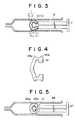
- Fig. 4is a cross-sectional view of an elastomer sliding stopper 41 of the prior art, in which a sliding part on the inner wall of a barrel 48 has annular protrusions 45a and 45b which are contacted with the inner wall.
- Syringes or injectorsmust be germ-free and dust-free in view of the purpose of the object and must have special physical properties such as liquid tightness, gas tightness and sliding property, which depend on the degree of contacting of the inner wall of a hard barrel with a sliding stopper consisting of an elastic material. Since every barrel has different straightness, smoothness and circular deformation of the inner wall and some errors in dimension and shape corresponding to the position, i.e. front part, central part and rear part, however, the above described degree of contacting differs every barrel and every position of a barrel.
- the diameter of a sliding stopperis ordinarily rendered larger than the average inner diameter of a barrel and the degree of contacting is increased to improve the liquid tightness and gas tightness.
- the laminated sliding stopper the inventors have proposedcan completely solve the problem of contamination with a silicone oil as described above, but in a case where there are errors passing the limit in dimension and shape as to the inner wall of a barrel, the laminated sliding stopper cannot fully follow up the surface fluctuation as compared with non-laminated sliding stoppers, thus often resulting in deterioration of the sealability or tightness during sliding, i.e. using the syringe. Furthermore, the laminated sliding stopper often meets with lowering of the tightness, in particular, in the case of twistdrawing when aspirating a liquid medicament or in the case of slant pushing when injecting a liquid medicament.
- a sliding stopper for a syringecomprising a body of elastomeric material whose part to be contacted with a liquid medicament and sliding part on the inner wall of a barrel are laminated with a resin film, such as of tetrafluoroethylene resin, ethylenetetrafluoroethylene resin or ultra-high molecular weight polyethylene resin, wherein the ratio of the length (Y) of such a surface that the outer circumferential part of the sliding stopper and the inner wall of the barrel are contacted with each other to the length (L) of the sliding part of the sliding stopper, Y/L, is in the range of 0.80 to 1.00, and the ratio of the length (L) of the sliding part to the outer diameter (D) of the sliding stopper, L/D is in the range of 0.25 to 1.00.
- a resin filmsuch as of tetrafluoroethylene resin, ethylenetetrafluoroethylene resin or ultra-high molecular weight polyethylene resin
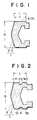
- Fig. 1 and Fig. 2are cross-sectional views of preferred embodiments of the sliding stopper for a syringe according to the present invention.
- Fig. 3is a cross-sectional view of another embodiment of the sliding stopper of the invention when applied to a syringe.
- Fig. 4 and Fig. 5are respectively cross-sectional views of a sliding stopper of the prior art and a syringe using this sliding stopper.
- a sliding stopper 1consists of a rubber part 2 and a laminated resin film part 3 and is fitted to the end of a plunger rod 7 and inserted in a syringe barrel 8 as shown in Fig. 3.
- the length of a sliding part 4 of the sliding stopper 1is designated as L
- the length of a part 5 of the sliding part 4, contacted with the inner wall of the syringe barrel 8is designated as Y
- the outer diameter of the sliding stopperis designated as D
- Yis 80 to 100 % of L, that is, Y/L is 0.80 to 1.00
- Lis 25 to 100 % of D, that is, L/D is 0.25 to 1.00.
- an annular hollow part 6can be provided between a contact part 51 (length Y1) and another contact part 52 (length Y2) in such a manner that the sum of Y1 and Y2 becomes 80 to almost 100 % of L.
- the length L of the sliding part 4is adjusted to about 6 to 15 mm, since the volume of an ordinary syringe corresponds to an injection liquid of 10 ml and this range of L can cover a liquid quantity of 3 to 25 ml.
- annular protrusions 45a and 45bare provided at both the ends of the sliding part of a stopper 41, as shown in Fig. 4 (laminated film not shown), so as to hold the sealability.
- Fig. 547 designates a plunger rod and 48, a barrel.
- the sealabilitycan largely be improved by adjusting substantially the overall surface of the sliding stopper, i.e. 80 to 100 % of the length L of the sliding surface to the length Y of the contact surface with the inner wall of a barrel.
- the sliding surfacehas no or few unevenness
- production of the sliding stopper by subjecting a rubber and resin film to molding and laminatingcan be accomplished without formation of scratches on convex parts and with a largely increased yield, thus lowering the production cost.
- the sealabilitycan well be held even in incorrect operations such as twist drawing and slant pushing by adjusting L to 25 to 100 % of D.
- a fluoro resin film having a small friction coefficientsuch as tetrafluoroethylene resin films (hereinafter referred to as TFE) or ethylene-tetrafluoroethylene resin films (hereinafter referred to as ETFE) is preferably used as the laminated layer 3 of the surface of the sliding stopper.
- TFEtetrafluoroethylene resin films
- ETFEethylene-tetrafluoroethylene resin films
- PEpolyethylene resins having an ultra-high molecular weight, i.e.
- the laminated layerhas preferably a thickness of 0.010 to 0.2 mm.
- Production of the sliding stoppercan be carried out by placing a film for lamination on the surface of a rubber sheet and then simultaneously subjecting to molding and laminating.
- a rubber sheetfor examples, natural rubber and synthetic rubbers can be used.
- the sliding stopper of the present embodimenthas the following advantages: In the sliding stopper, the surface of an elastic rubber body is laminated with a resin film with an excellent chemical resistance, but the sealability or tightness of the sliding stopper can be rendered sufficient enough to resist dispersion of the inner diameter or shape of a syringe barrel and incorrect operation of the syringe during use by specifying the relationship between the length of such a surface that the outer circumferential part of the sliding stopper and the inner wall of the barrel are contacted with each other, and the relationship between the length of the sliding part of the sliding stopper and the outer diameter of the sliding stopper. Furthermore, the use of silicone oil is not required and contamination of a liquid medicament with fine particles due to it can be prevented.
- the sliding stopper of the present embodimentcan favorably be applied to a syringe or injector for dosing a high purity medicament with in high security as well as a syringe additionally serving as a container for a liquid medicament, because of its high chemical resistance and sealability.
- Sliding stoppers of the present inventioneach having a shape as shown in Fig. 1 or Fig. 2 and a laminated layer consisting of TFE, ETFE or PE, were prepared while varying Y/L and L/D within the scope of the present invention (Examples 1 to 6).
- Leakage of airwas examined when 2 ml of water was charged in a syringe barrel, a needle opening part was directed upward and clogged and a plunger rod was withdrawn by fingers while revolving it by about 90 degrees.
- the load(initial value and sliding value) was measured by an Autograph DCS-100 type (commercial name, manufactured by Shimazu Seisakusho KK).
- “Good”means such a state that when a plunger rod is thrust in a syringe barrel by hand, it is moved in smooth and continuous manner, while “knocking” means such a state that the plunger rod is intermittently moved.
- the knocking propertyis an important property to judge whether an injection medicament is precisely dosed as predetermined or not.
- This testwas carried out by aspirating 5 ml of purified water by a syringe, discharging the water by thrusting and collecting, repeating this procedure three times to obtain a test liquid and after allowing to stand for 30 minutes, subjecting 12 ml of the test liquid to measurement using an optical fine particle tester (RION).
- RIONoptical fine particle tester
- NDmeans an amount of lower than the limit which can be detected.
Landscapes
- Health & Medical Sciences (AREA)
- Vascular Medicine (AREA)
- Engineering & Computer Science (AREA)
- Anesthesiology (AREA)
- Biomedical Technology (AREA)
- Heart & Thoracic Surgery (AREA)
- Hematology (AREA)
- Life Sciences & Earth Sciences (AREA)
- Animal Behavior & Ethology (AREA)
- General Health & Medical Sciences (AREA)
- Public Health (AREA)
- Veterinary Medicine (AREA)
- Infusion, Injection, And Reservoir Apparatuses (AREA)
- Materials For Medical Uses (AREA)
Description
- This invention relates to a sliding or movable stopper for an injector or syringe used, eg, for dosing a human body or animal with a liquid medicament.
- An injector is generally constructed of a
barrel 48 of a glass or thermoplastic plastic, asliding stopper 41 of a glass, rubber or thermoplastic elastomer and aplunger rod 47, as shown in Fig. 5. A combination of a glass barrel and glass sliding stopper has rarely been used recently, but a combination of a glass barrel and elastomer sliding stopper has been used for a syringe additionally serving as a container to be filled with a liquid medicament and a combination of a plastic barrel and elastomer sliding stopper has ordinarily been used for a throwaway disposable syringe. Fig. 4 is a cross-sectional view of anelastomer sliding stopper 41 of the prior art, in which a sliding part on the inner wall of abarrel 48 hasannular protrusions - Syringes or injectors must be germ-free and dust-free in view of the purpose of the object and must have special physical properties such as liquid tightness, gas tightness and sliding property, which depend on the degree of contacting of the inner wall of a hard barrel with a sliding stopper consisting of an elastic material. Since every barrel has different straightness, smoothness and circular deformation of the inner wall and some errors in dimension and shape corresponding to the position, i.e. front part, central part and rear part, however, the above described degree of contacting differs every barrel and every position of a barrel.
- In order to correct such a dispersion, the diameter of a sliding stopper is ordinarily rendered larger than the average inner diameter of a barrel and the degree of contacting is increased to improve the liquid tightness and gas tightness. In this case, however, it is required to coat the sliding part with a silicone oil as a lubricant to make up for the thus lowered sliding property and the use of this silicone oil causes a problem of fine particle contamination of a medicament to be dosed.
- Under the situation, the inventors have proposed a high quality syringe in which no silicone oil is required by laminating the surface of a sliding stopper with a fluoro resin and the contamination due to the silicone oil can thus be prevented, as disclosed in Japanese Patent Laid-Open Publication Nos. 243122/1986 (EP-A-0264273) and 139668/1987.
- The laminated sliding stopper the inventors have proposed can completely solve the problem of contamination with a silicone oil as described above, but in a case where there are errors passing the limit in dimension and shape as to the inner wall of a barrel, the laminated sliding stopper cannot fully follow up the surface fluctuation as compared with non-laminated sliding stoppers, thus often resulting in deterioration of the sealability or tightness during sliding, i.e. using the syringe. Furthermore, the laminated sliding stopper often meets with lowering of the tightness, in particular, in the case of twistdrawing when aspirating a liquid medicament or in the case of slant pushing when injecting a liquid medicament.
- It is an object of the present invention to provide a sliding stopper for a syringe used for the injection of a liquid medicament, whereby the above described problems of the prior art can be solved.
- It is another object of the present invention to provide a laminated sliding stopper with an improved sealability during sliding.
- These objects can be attained by a sliding stopper for a syringe, comprising a body of elastomeric material whose part to be contacted with a liquid medicament and sliding part on the inner wall of a barrel are laminated with a resin film, such as of tetrafluoroethylene resin, ethylenetetrafluoroethylene resin or ultra-high molecular weight polyethylene resin,
wherein the ratio of the length (Y) of such a surface that the outer circumferential part of the sliding stopper and the inner wall of the barrel are contacted with each other to the length (L) of the sliding part of the sliding stopper, Y/L, is in the range of 0.80 to 1.00, and the ratio of the length (L) of the sliding part to the outer diameter (D) of the sliding stopper, L/D is in the range of 0.25 to 1.00. - The accompanying drawings are to illustrate by way of example and embodiment of the present invention.
- Fig. 1 and Fig. 2 are cross-sectional views of preferred embodiments of the sliding stopper for a syringe according to the present invention.
- Fig. 3 is a cross-sectional view of another embodiment of the sliding stopper of the invention when applied to a syringe.
- Fig. 4 and Fig. 5 are respectively cross-sectional views of a sliding stopper of the prior art and a syringe using this sliding stopper.
- Referring to Fig. 1 and Fig. 2 showing cross-sectional views of preferred embodiments of the sliding stopper for a syringe according to the present invention and Fig. 3 showing a cross-sectional view of another embodiment of the sliding stopper of the present invention when applied to a syringe, a sliding stopper 1 consists of a
rubber part 2 and a laminatedresin film part 3 and is fitted to the end of a plunger rod 7 and inserted in asyringe barrel 8 as shown in Fig. 3. - When the length of a
sliding part 4 of the sliding stopper 1 is designated as L, the length of apart 5 of thesliding part 4, contacted with the inner wall of thesyringe barrel 8, is designated as Y and the outer diameter of the sliding stopper is designated as D, Y is 80 to 100 % of L, that is, Y/L is 0.80 to 1.00, and L is 25 to 100 % of D, that is, L/D is 0.25 to 1.00. In the case of Fig. 1, thecontact part 5 with theinner wall 8 of thesyringe barrel 8 is an outer circumferential even surface of a cylinder and Y = L, i.e. Y is 100 % of L, while as shown in Fig. 2, an annularhollow part 6 can be provided between a contact part 51 (length Y₁) and another contact part 52 (length Y₂) in such a manner that the sum of Y₁ and Y₂ becomes 80 to almost 100 % of L. Generally, the length L of thesliding part 4 is adjusted to about 6 to 15 mm, since the volume of an ordinary syringe corresponds to an injection liquid of 10 ml and this range of L can cover a liquid quantity of 3 to 25 ml. - In the laminated sliding stopper of the prior art,
annular protrusions stopper 41, as shown in Fig. 4 (laminated film not shown), so as to hold the sealability. In Fig. 5, 47 designates a plunger rod and 48, a barrel. In the present embodiment, on the contrary, the sealability can largely be improved by adjusting substantially the overall surface of the sliding stopper, i.e. 80 to 100 % of the length L of the sliding surface to the length Y of the contact surface with the inner wall of a barrel. Since the sliding surface has no or few unevenness, production of the sliding stopper by subjecting a rubber and resin film to molding and laminating can be accomplished without formation of scratches on convex parts and with a largely increased yield, thus lowering the production cost. Furthermore, the sealability can well be held even in incorrect operations such as twist drawing and slant pushing by adjusting L to 25 to 100 % of D. - The factor having the largest influence upon the sliding property is the friction resistance of the surface of a sliding stopper. Thus, a fluoro resin film having a small friction coefficient such as tetrafluoroethylene resin films (hereinafter referred to as TFE) or ethylene-tetrafluoroethylene resin films (hereinafter referred to as ETFE) is preferably used as the laminated
layer 3 of the surface of the sliding stopper. In addition, polyethylene resins (referred to as PE) having an ultra-high molecular weight, i.e. at least 100 x 10⁴, which have lately been developed, are also preferably used as the material of the laminated layer, because of having a similar friction coefficient to fluororesins, being sufficiently resistant to practical use and also resistant to a gamma-ray sterilization method which has lately been used often and being produced with a low cost. The laminated layer has preferably a thickness of 0.010 to 0.2 mm. - Production of the sliding stopper can be carried out by placing a film for lamination on the surface of a rubber sheet and then simultaneously subjecting to molding and laminating. For this rubber sheet, for examples, natural rubber and synthetic rubbers can be used.
- The sliding stopper of the present embodiment has the following advantages:
In the sliding stopper, the surface of an elastic rubber body is laminated with a resin film with an excellent chemical resistance, but the sealability or tightness of the sliding stopper can be rendered sufficient enough to resist dispersion of the inner diameter or shape of a syringe barrel and incorrect operation of the syringe during use by specifying the relationship between the length of such a surface that the outer circumferential part of the sliding stopper and the inner wall of the barrel are contacted with each other, and the relationship between the length of the sliding part of the sliding stopper and the outer diameter of the sliding stopper. Furthermore, the use of silicone oil is not required and contamination of a liquid medicament with fine particles due to it can be prevented. Therefore, the sliding stopper of the present embodiment can favorably be applied to a syringe or injector for dosing a high purity medicament with in high security as well as a syringe additionally serving as a container for a liquid medicament, because of its high chemical resistance and sealability. - The following examples are given in order to illustrate the present invention in greater detail without limiting the same.
- Sliding stoppers of the present invention, each having a shape as shown in Fig. 1 or Fig. 2 and a laminated layer consisting of TFE, ETFE or PE, were prepared while varying Y/L and L/D within the scope of the present invention (Examples 1 to 6).
- On the other hand, laminated layer-free stoppers as shown in Fig. 4 (Comparative Examples 1 to 3, commercially available) and a laminated stopper (Comparative Example 4) were prepared.
- These samples were subjected to the elution or extraction test according to the legal test method, as a physical property test of a sliding stopper itself, and to the legal physical test and the physical test and fine particle test according to the independence test standard to evaluate the properties when used for a syringe. The outlines of these test methods are illustrated below and the test results are shown in the following table with the standard values:
- 1) According to the test methods described in Notification No. 442 of the Welfare Ministry, Standard for Syringe Barrel of Disposal type, extraction tests with water (A) or a solvent (B) and physical tests (C) including a pressure test, aspiration test and movement test were carried out.
- 2) According to 44 Test Method of Rubber Stopper for Liquid Transfusion of 11th Revision, Japanese Pharmacopoeia, an extraction test (D) was carried.
- Leakage of air was examined when 2 ml of water was charged in a syringe barrel, a needle opening part was directed upward and clogged and a plunger rod was withdrawn by fingers while revolving it by about 90 degrees.
- Leakage of water was examined when 2 ml of water was charged in a syringe barrel, a plunger rod was positioned in such a manner that the sliding stopper be at the maximum scale mark, a needle opening was directed upward and clogged and the plunger rod was pushed under slant state.
- When a syringe barrel to which an injection needle was not attached was fixed and a plunger rod was thrust to move the sliding stopper, the load (initial value and sliding value) was measured by an Autograph DCS-100 type (commercial name, manufactured by Shimazu Seisakusho KK).
- "Good" means such a state that when a plunger rod is thrust in a syringe barrel by hand, it is moved in smooth and continuous manner, while "knocking" means such a state that the plunger rod is intermittently moved. The knocking property is an important property to judge whether an injection medicament is precisely dosed as predetermined or not.
- After purified water was aspirated in a syringe to the maximum scale mark and then discharged by 1 ml by thrusting a plunger rod under such a state that a needle was directed upward, the presence or absence of bubbles was visually examined. Mark ○ shows bubble-free state and mark x shows a bubbled state.
- This test was carried out by aspirating 5 ml of purified water by a syringe, discharging the water by thrusting and collecting, repeating this procedure three times to obtain a test liquid and after allowing to stand for 30 minutes, subjecting 12 ml of the test liquid to measurement using an optical fine particle tester (RION). In each Example, 20 samples were used and subjected to this test and the results are shown in the following table as mean values per one sample.
- The assessment of the results is represented by "Very Good" Ⓞ, "Good" ○ , "Normal" △ and "Unsuitable" x.
- "ND" means an amount of lower than the limit which can be detected.


- As can be seen from these results, the commercially available laminated layer-free sliding stoppers as shown in Fig. 4 (Comparative Examples 1 to 3) all give good results in the physical tests, but inferior results in the fine particle test which will cause a problem on safety considering a bad influence on a human body and the sliding stopper having a laminated layer and a shape as shown in Fig. 4 (Comparative Example 4) exhibits a very high safety, but meets with a problem in the physical tests. On the other hand, the samples of the present invention give much better results in the tests, which can favorably be compared with those of Comparative Examples.


Claims (3)
- A sliding stopper (1) for a syringe, comprising a body (2) of elastomeric material, such as rubber, having a contact part, which in use contacts a liquid medicament, and a sliding part (4), which in use slides along an inner wall (8) of a barrel, which contact and sliding parts are laminated with a resin film (3) having a low friction co-efficient, wherein the resin film (3) is selected from the group consisting of films of tetrafluoroethylene resin, ethylene-tetrafluoroethylene copolymer resins and ultra-high molecular weight polyethylene resin, characterised in that the ratio of Y/L of the length (Y) of the sliding part, which in use contacts the inner wall of the barrel, to the actual length (L) of the sliding part of the sliding stopper, is in the range of 0.8 to 1, and the ratio L/D of the length (L) of the sliding part to the outer diameter (D) of the sliding stopper is in the range of 0.25 to 1.
- A sliding stopper (1) for a syringe as claimed in claim 1 wherein the length (L) of the sliding part (4) is from 6mm to 15mm.
- A sliding stopper (1) for a syringe as claimed in claim 1, wherein the contacted part (5) of the sliding stopper with the inner wall (8) of the barrel, having the length (Y), is provided with an annular hollow part to divide into two contacted parts respectively having lengths Y₁ and Y₂ in such a manner that


Applications Claiming Priority (2)
| Application Number | Priority Date | Filing Date | Title |
|---|---|---|---|
| JP33730/88 | 1988-03-16 | ||
| JP1988033730UJPH0534669Y2 (en) | 1988-03-16 | 1988-03-16 |
Publications (2)
| Publication Number | Publication Date |
|---|---|
| EP0338671A1 EP0338671A1 (en) | 1989-10-25 |
| EP0338671B1true EP0338671B1 (en) | 1994-05-18 |
Family
ID=12394518
Family Applications (1)
| Application Number | Title | Priority Date | Filing Date |
|---|---|---|---|
| EP89302432AExpired - LifetimeEP0338671B1 (en) | 1988-03-16 | 1989-03-13 | A sliding stopper for a syringe |
Country Status (4)
| Country | Link |
|---|---|
| US (1) | US5009646A (en) |
| EP (1) | EP0338671B1 (en) |
| JP (1) | JPH0534669Y2 (en) |
| DE (1) | DE68915328T2 (en) |
Cited By (4)
| Publication number | Priority date | Publication date | Assignee | Title |
|---|---|---|---|---|
| US7587820B2 (en) | 2001-12-27 | 2009-09-15 | Terumo Kabushiki Kaisha | Metal tubular body and manufacturing method thereof |
| US8034026B2 (en) | 2001-05-18 | 2011-10-11 | Deka Products Limited Partnership | Infusion pump assembly |
| US8113244B2 (en) | 2006-02-09 | 2012-02-14 | Deka Products Limited Partnership | Adhesive and peripheral systems and methods for medical devices |
| US8262616B2 (en) | 2008-10-10 | 2012-09-11 | Deka Products Limited Partnership | Infusion pump assembly |
Families Citing this family (122)
| Publication number | Priority date | Publication date | Assignee | Title |
|---|---|---|---|---|
| BE1002383A3 (en)* | 1988-08-25 | 1991-01-22 | Helvoet Pharma | METHOD FOR TREATING VULLCANIZED PHARMACEUTICAL RUBBER PRODUCTS AND TREATED VULLCANIZED PHARMACEUTICAL RUBBER PRODUCTS |
| JPH02199673A (en)* | 1989-01-27 | 1990-08-08 | Nec Corp | Recording and reproducing vcr with video recording picture data guarding function |
| JPH03140231A (en)* | 1989-10-26 | 1991-06-14 | Nissho Corp | Rubber plug for vial |
| JPH04263750A (en)* | 1991-01-21 | 1992-09-18 | Mitsubishi Electric Corp | Refrigerator |
| JP2563751Y2 (en)* | 1991-02-12 | 1998-02-25 | 株式会社大協精工 | Syringe stopper |
| US6968375B1 (en)* | 1997-03-28 | 2005-11-22 | Health Hero Network, Inc. | Networked system for interactive communication and remote monitoring of individuals |
| US5354286A (en)* | 1993-12-07 | 1994-10-11 | Survival Technology, Inc. | Injection device having polyparaxylylene coated container |
| US5413563A (en)* | 1994-05-06 | 1995-05-09 | Sterling Winthrop Inc. | Pre-filled syringe having a plunger, plunger insert and plunger rod |
| US5607400A (en) | 1995-05-19 | 1997-03-04 | Becton, Dickinson And Company | Pre-fillable syringe and stopper assembly therefor |
| JP3198065B2 (en) | 1996-08-19 | 2001-08-13 | 株式会社大協精工 | Hygiene container |
| US6142977A (en)* | 1996-10-18 | 2000-11-07 | Schering Ag | Prefilled, sterilized syringe with a new and improved plug |
| AU6810998A (en)* | 1996-10-18 | 1998-05-15 | Schering Aktiengesellschaft | Syringe with a polyethylene stopper |
| DK0838229T3 (en)* | 1996-10-28 | 2003-08-18 | Daikyo Seiko Ltd | Syringe with a Luer lock part |
| US6053895A (en)* | 1996-11-05 | 2000-04-25 | Schering Aktiengesellschaft | Syringe with a new and improved plug |
| JP3387775B2 (en)* | 1997-05-22 | 2003-03-17 | 株式会社大協精工 | Sealing stopper for syringe and prefilled syringe |
| US6200627B1 (en)* | 1998-03-17 | 2001-03-13 | Becton, Dickinson And Company | Low silicone glass prefillable syringe |
| JP4132208B2 (en)* | 1998-04-28 | 2008-08-13 | 大成化工株式会社 | Syringe container manufacturing apparatus and syringe container manufacturing method |
| JP2000140103A (en)* | 1998-11-05 | 2000-05-23 | Daikyo Seiko Ltd | Plunger for injector |
| JP3908895B2 (en) | 1999-07-12 | 2007-04-25 | 株式会社大協精工 | Manufacturing method of rubber stopper |
| DE10036830A1 (en)* | 2000-07-28 | 2002-02-21 | Schott Glas | dosing |
| JP2002089717A (en)* | 2000-09-14 | 2002-03-27 | Terumo Corp | Gasket |
| JP4531968B2 (en)* | 2000-12-11 | 2010-08-25 | 日東電工株式会社 | Manufacturing method of syringe stopper film |
| EP1815879A3 (en) | 2001-05-18 | 2007-11-14 | Deka Products Limited Partnership | Infusion set for a fluid pump |
| US20040010235A1 (en)* | 2002-07-11 | 2004-01-15 | Weilbacher Eugene E. | Anti-reflux syringe |
| JP4460278B2 (en)* | 2003-12-17 | 2010-05-12 | 株式会社大協精工 | Seal plug for syringe and prefilled syringe |
| GB2414406B (en)* | 2004-05-28 | 2009-03-18 | Cilag Ag Int | Injection device |
| GB2414401B (en)* | 2004-05-28 | 2009-06-17 | Cilag Ag Int | Injection device |
| GB2414400B (en) | 2004-05-28 | 2009-01-14 | Cilag Ag Int | Injection device |
| GB2414402B (en) | 2004-05-28 | 2009-04-22 | Cilag Ag Int | Injection device |
| GB2414403B (en)* | 2004-05-28 | 2009-01-07 | Cilag Ag Int | Injection device |
| GB2414399B (en)* | 2004-05-28 | 2008-12-31 | Cilag Ag Int | Injection device |
| GB2414409B (en)* | 2004-05-28 | 2009-11-18 | Cilag Ag Int | Injection device |
| GB2414775B (en)* | 2004-05-28 | 2008-05-21 | Cilag Ag Int | Releasable coupling and injection device |
| US20060173418A1 (en)* | 2004-12-13 | 2006-08-03 | Arrow International, Inc. | Loss of resistance syringe |
| GB2425062B (en)* | 2005-04-06 | 2010-07-21 | Cilag Ag Int | Injection device |
| GB2424837B (en)* | 2005-04-06 | 2010-10-06 | Cilag Ag Int | Injection device |
| GB2424835B (en)* | 2005-04-06 | 2010-06-09 | Cilag Ag Int | Injection device (modified trigger) |
| GB2424838B (en)* | 2005-04-06 | 2011-02-23 | Cilag Ag Int | Injection device (adaptable drive) |
| GB2427826B (en) | 2005-04-06 | 2010-08-25 | Cilag Ag Int | Injection device comprising a locking mechanism associated with integrally formed biasing means |
| GB2424836B (en) | 2005-04-06 | 2010-09-22 | Cilag Ag Int | Injection device (bayonet cap removal) |
| FR2885412B1 (en)* | 2005-05-03 | 2008-12-05 | Commissariat Energie Atomique | DEVICE AND METHOD FOR COLLECTING AND TRANSPORTING |
| CN101252961B (en)* | 2005-08-29 | 2011-07-20 | 韦斯特制药服务公司 | Dual material plunger tip for use with a syringe |
| PL1759729T3 (en)* | 2005-08-30 | 2010-09-30 | Cilag Gmbh Int | Needle assembly for a prefilled syringe system |
| WO2007030630A2 (en)* | 2005-09-07 | 2007-03-15 | Covidien Ag | Syringe construction |
| US20110098656A1 (en)* | 2005-09-27 | 2011-04-28 | Burnell Rosie L | Auto-injection device with needle protecting cap having outer and inner sleeves |
| US12151080B2 (en) | 2006-02-09 | 2024-11-26 | Deka Products Limited Partnership | Adhesive and peripheral systems and methods for medical devices |
| US12274857B2 (en) | 2006-02-09 | 2025-04-15 | Deka Products Limited Partnership | Method and system for shape-memory alloy wire control |
| US11497846B2 (en) | 2006-02-09 | 2022-11-15 | Deka Products Limited Partnership | Patch-sized fluid delivery systems and methods |
| US11364335B2 (en) | 2006-02-09 | 2022-06-21 | Deka Products Limited Partnership | Apparatus, system and method for fluid delivery |
| US10010669B2 (en) | 2006-02-09 | 2018-07-03 | Deka Products Limited Partnership | Systems and methods for fluid delivery |
| US11027058B2 (en) | 2006-02-09 | 2021-06-08 | Deka Products Limited Partnership | Infusion pump assembly |
| US12070574B2 (en) | 2006-02-09 | 2024-08-27 | Deka Products Limited Partnership | Apparatus, systems and methods for an infusion pump assembly |
| US12370305B2 (en) | 2006-02-09 | 2025-07-29 | Deka Products Limited Partnership | Patch-sized fluid delivery systems and methods |
| US11478623B2 (en) | 2006-02-09 | 2022-10-25 | Deka Products Limited Partnership | Infusion pump assembly |
| GB2438593B (en) | 2006-06-01 | 2011-03-30 | Cilag Gmbh Int | Injection device (cap removal feature) |
| GB2438591B (en)* | 2006-06-01 | 2011-07-13 | Cilag Gmbh Int | Injection device |
| GB2438590B (en)* | 2006-06-01 | 2011-02-09 | Cilag Gmbh Int | Injection device |
| CA2677667A1 (en) | 2007-02-09 | 2008-08-14 | Deka Products Limited Partnership | Automated insertion assembly |
| DK2165724T3 (en)* | 2007-06-20 | 2018-11-26 | Daikyo Seiko Ltd | Sliding valve installed in an injector and injector with the sliding valve |
| CA2919786C (en) | 2007-12-31 | 2019-10-22 | Deka Products Limited Partnership | Infusion pump assembly |
| US9526830B2 (en) | 2007-12-31 | 2016-12-27 | Deka Products Limited Partnership | Wearable pump assembly |
| US10080704B2 (en) | 2007-12-31 | 2018-09-25 | Deka Products Limited Partnership | Apparatus, system and method for fluid delivery |
| US8881774B2 (en) | 2007-12-31 | 2014-11-11 | Deka Research & Development Corp. | Apparatus, system and method for fluid delivery |
| US8900188B2 (en) | 2007-12-31 | 2014-12-02 | Deka Products Limited Partnership | Split ring resonator antenna adapted for use in wirelessly controlled medical device |
| US10188787B2 (en) | 2007-12-31 | 2019-01-29 | Deka Products Limited Partnership | Apparatus, system and method for fluid delivery |
| US9456955B2 (en) | 2007-12-31 | 2016-10-04 | Deka Products Limited Partnership | Apparatus, system and method for fluid delivery |
| GB2461086B (en)* | 2008-06-19 | 2012-12-05 | Cilag Gmbh Int | Injection device |
| GB2461088B (en)* | 2008-06-19 | 2012-09-26 | Cilag Gmbh Int | Injection device |
| GB2461084B (en) | 2008-06-19 | 2012-09-26 | Cilag Gmbh Int | Fluid transfer assembly |
| GB2461089B (en) | 2008-06-19 | 2012-09-19 | Cilag Gmbh Int | Injection device |
| GB2461085B (en)* | 2008-06-19 | 2012-08-29 | Cilag Gmbh Int | Injection device |
| GB2461087B (en)* | 2008-06-19 | 2012-09-26 | Cilag Gmbh Int | Injection device |
| US9180245B2 (en) | 2008-10-10 | 2015-11-10 | Deka Products Limited Partnership | System and method for administering an infusible fluid |
| US8066672B2 (en) | 2008-10-10 | 2011-11-29 | Deka Products Limited Partnership | Infusion pump assembly with a backup power supply |
| US8708376B2 (en) | 2008-10-10 | 2014-04-29 | Deka Products Limited Partnership | Medium connector |
| US8267892B2 (en) | 2008-10-10 | 2012-09-18 | Deka Products Limited Partnership | Multi-language / multi-processor infusion pump assembly |
| US8016789B2 (en) | 2008-10-10 | 2011-09-13 | Deka Products Limited Partnership | Pump assembly with a removable cover assembly |
| US12186531B2 (en) | 2008-10-10 | 2025-01-07 | Deka Products Limited Partnership | Infusion pump assembly |
| US8223028B2 (en) | 2008-10-10 | 2012-07-17 | Deka Products Limited Partnership | Occlusion detection system and method |
| US12370327B2 (en) | 2008-10-10 | 2025-07-29 | Deka Products Limited Partnership | Infusion pump methods, systems and apparatus |
| EP2251454B1 (en) | 2009-05-13 | 2014-07-23 | SiO2 Medical Products, Inc. | Vessel coating and inspection |
| US8322577B2 (en)* | 2009-04-24 | 2012-12-04 | Agilent Technologies, Inc. | Syringe with improved plunger |
| US9458536B2 (en) | 2009-07-02 | 2016-10-04 | Sio2 Medical Products, Inc. | PECVD coating methods for capped syringes, cartridges and other articles |
| WO2011008966A2 (en) | 2009-07-15 | 2011-01-20 | Deka Products Limited Partnership | Apparatus, systems and methods for an infusion pump assembly |
| US9597458B2 (en)* | 2009-10-29 | 2017-03-21 | W. L. Gore & Associates, Inc. | Fluoropolymer barrier materials for containers |
| US8722178B2 (en)* | 2009-10-29 | 2014-05-13 | W. L. Gore & Associates, Inc. | Syringe stopper |
| US10471212B2 (en) | 2009-10-29 | 2019-11-12 | W. L. Gore & Associates, Inc. | Silicone free drug delivery devices |
| CA3033439C (en) | 2010-01-22 | 2021-04-06 | Deka Products Limited Partnership | Method and system for shape-memory alloy wire control |
| US11612697B2 (en)* | 2010-10-29 | 2023-03-28 | W. L. Gore & Associates, Inc. | Non-fluoropolymer tie layer and fluoropolymer barrier layer |
| US9878101B2 (en) | 2010-11-12 | 2018-01-30 | Sio2 Medical Products, Inc. | Cyclic olefin polymer vessels and vessel coating methods |
| JP5934335B2 (en) | 2011-03-28 | 2016-06-15 | ベクトン・ディキンソン・アンド・カンパニーBecton, Dickinson And Company | Plastic stopper |
| US9272095B2 (en) | 2011-04-01 | 2016-03-01 | Sio2 Medical Products, Inc. | Vessels, contact surfaces, and coating and inspection apparatus and methods |
| US9539394B2 (en) | 2011-04-15 | 2017-01-10 | W. L. Gore & Associates, Inc. | Method of reducing friction between syringe components |
| JP5922404B2 (en)* | 2011-12-28 | 2016-05-24 | 住友ゴム工業株式会社 | Laminated gasket |
| US11524151B2 (en) | 2012-03-07 | 2022-12-13 | Deka Products Limited Partnership | Apparatus, system and method for fluid delivery |
| PL3777834T3 (en) | 2012-06-01 | 2022-05-30 | Novartis Ag | Syringe |
| US9901725B2 (en) | 2012-10-01 | 2018-02-27 | Bayer Healthcare Llc | Overmolded medical connector tubing and method |
| US9664626B2 (en) | 2012-11-01 | 2017-05-30 | Sio2 Medical Products, Inc. | Coating inspection method |
| US9903782B2 (en) | 2012-11-16 | 2018-02-27 | Sio2 Medical Products, Inc. | Method and apparatus for detecting rapid barrier coating integrity characteristics |
| US9764093B2 (en) | 2012-11-30 | 2017-09-19 | Sio2 Medical Products, Inc. | Controlling the uniformity of PECVD deposition |
| AU2013352436B2 (en) | 2012-11-30 | 2018-10-25 | Sio2 Medical Products, Inc. | Controlling the uniformity of PECVD deposition on medical syringes, cartridges, and the like |
| US20160015898A1 (en) | 2013-03-01 | 2016-01-21 | Sio2 Medical Products, Inc. | Plasma or cvd pre-treatment for lubricated pharmaceutical package, coating process and apparatus |
| JP6453841B2 (en) | 2013-03-11 | 2019-01-16 | エスアイオーツー・メディカル・プロダクツ・インコーポレイテッド | Coated packaging |
| US9937099B2 (en) | 2013-03-11 | 2018-04-10 | Sio2 Medical Products, Inc. | Trilayer coated pharmaceutical packaging with low oxygen transmission rate |
| US20160017490A1 (en) | 2013-03-15 | 2016-01-21 | Sio2 Medical Products, Inc. | Coating method |
| GB2515039B (en) | 2013-06-11 | 2015-05-27 | Cilag Gmbh Int | Injection Device |
| GB2517896B (en) | 2013-06-11 | 2015-07-08 | Cilag Gmbh Int | Injection device |
| GB2515038A (en) | 2013-06-11 | 2014-12-17 | Cilag Gmbh Int | Injection device |
| GB2515032A (en) | 2013-06-11 | 2014-12-17 | Cilag Gmbh Int | Guide for an injection device |
| US9617020B2 (en) | 2013-07-03 | 2017-04-11 | Deka Products Limited Partnership | Apparatus, system and method for fluid delivery |
| IL295010B1 (en) | 2015-03-10 | 2025-06-01 | Regeneron Pharma | Pollution-free piercing system and method |
| US10471211B2 (en) | 2016-01-15 | 2019-11-12 | W. L. Gore & Associates, Inc. | Medical delivery device with laminated stopper |
| WO2017127534A1 (en) | 2016-01-21 | 2017-07-27 | Merit Medical Systems, Inc. | Partially lubricated syringe barrels, plungers, and seal members and related methods |
| US10653845B2 (en) | 2016-01-21 | 2020-05-19 | Merit Medical Systems, Inc. | Coverings for syringe plunger tips and methods related thereto |
| CN119950880A (en) | 2017-05-05 | 2025-05-09 | 里珍纳龙药品有限公司 | Auto-injectors and related methods of use |
| US10058658B1 (en)* | 2017-05-26 | 2018-08-28 | Precision Polymer Products, Inc. | Film faced articles and methods of manufacturing the same |
| DE212017000337U1 (en)* | 2017-06-29 | 2020-01-30 | Regeneron Pharmaceuticals, Inc. | Device for overfilling pharmaceutical containers |
| US11350945B2 (en) | 2017-11-13 | 2022-06-07 | Merit Medical Systems, Inc. | Staged deflation syringe systems and associated methods |
| CA3098372A1 (en) | 2018-04-24 | 2019-10-31 | Deka Products Limited Partnership | Apparatus and system for fluid delivery |
| AU2019344594B2 (en)* | 2018-09-20 | 2024-09-26 | Teva Pharmaceuticals International Gmbh | Injection spring for aged prefilled syringe and auto injector |
| US11933401B2 (en)* | 2020-10-09 | 2024-03-19 | Enplas Corporation | Plunger, instrument, and mold |
| USD1007676S1 (en) | 2021-11-16 | 2023-12-12 | Regeneron Pharmaceuticals, Inc. | Wearable autoinjector |
Family Cites Families (20)
| Publication number | Priority date | Publication date | Assignee | Title |
|---|---|---|---|---|
| FR358858A (en)* | 1905-10-25 | 1906-03-10 | Emilien Viel | Auto-injectable ampoules with metal tips applicable to all kinds of syringes |
| GB551545A (en)* | 1942-01-13 | 1943-02-26 | Samuel James Everett | Improvements in or relating to hypodermic and like syringes |
| US2578394A (en)* | 1947-12-04 | 1951-12-11 | Premo Pharmaceutical Lab Inc | Hypodermic syringe |
| NL77799C (en)* | 1950-07-20 | |||
| US2607342A (en)* | 1950-11-24 | 1952-08-19 | Martin S Abel | Syringe |
| GB771565A (en)* | 1954-04-15 | 1957-04-03 | S & R J Everett & Co Ltd | Improvements relating to hypodermic syringe members |
| US2895773A (en)* | 1956-10-22 | 1959-07-21 | Robert K Mcconnaughey | Variable diameter tensed ring piston |
| US3050059A (en)* | 1959-05-25 | 1962-08-21 | Baxter Don Inc | Hypodermic syringe |
| FR2025843A1 (en)* | 1968-12-11 | 1970-09-11 | Becton Dickinson Co | Syringe piston wead having thermoplastic - sheath |
| BE756550A (en)* | 1969-09-23 | 1971-03-01 | Sherwood Medical Ind Inc | REAR LOADING SYRINGE AND PROCEDURE FOR ITS FILLING |
| US3766918A (en)* | 1971-09-07 | 1973-10-23 | J Kessel | Self-aspirating hypodermic ampule |
| US3998224A (en)* | 1973-08-15 | 1976-12-21 | Arias Marcelo Chiquiar | Disposable self-destructible syringes which render themselves unreusable |
| US3958570A (en)* | 1974-09-03 | 1976-05-25 | Vogelman Joseph H | Syringes and syringe capsules |
| JPS6057873B2 (en)* | 1977-10-03 | 1985-12-17 | 東芝シリコ−ン株式会社 | Syringe |
| JPS5918427B2 (en)* | 1979-10-09 | 1984-04-27 | テルモ株式会社 | gasket for syringe |
| DE3138536A1 (en)* | 1981-09-28 | 1983-04-07 | Walter Graf U. Co Gmbh & Co, 6980 Wertheim | PISTON FOR A PRECISION DISPENSER |
| FR2547201A1 (en)* | 1983-06-08 | 1984-12-14 | Villette Alain | Piston for anaesthetic cartridge |
| JPS62139668A (en)* | 1985-12-16 | 1987-06-23 | 株式会社大協精工 | Laminated plug for syringe |
| US4685910A (en)* | 1986-01-21 | 1987-08-11 | Abbott Laboratories | Apparatus and method for delivering secondary fluids to a patient using an intravenous administration set feeding a primary fluid |
| US4820278A (en)* | 1988-01-13 | 1989-04-11 | The Boeing Company | Non-contaminating renewable syringe |
- 1988
- 1988-03-16JPJP1988033730Upatent/JPH0534669Y2/janot_activeExpired - Lifetime
- 1989
- 1989-03-13EPEP89302432Apatent/EP0338671B1/ennot_activeExpired - Lifetime
- 1989-03-13DEDE68915328Tpatent/DE68915328T2/ennot_activeExpired - Lifetime
- 1989-03-14USUS07/324,037patent/US5009646A/ennot_activeExpired - Lifetime
Cited By (9)
| Publication number | Priority date | Publication date | Assignee | Title |
|---|---|---|---|---|
| US8034026B2 (en) | 2001-05-18 | 2011-10-11 | Deka Products Limited Partnership | Infusion pump assembly |
| US7587820B2 (en) | 2001-12-27 | 2009-09-15 | Terumo Kabushiki Kaisha | Metal tubular body and manufacturing method thereof |
| US8113244B2 (en) | 2006-02-09 | 2012-02-14 | Deka Products Limited Partnership | Adhesive and peripheral systems and methods for medical devices |
| US8414522B2 (en) | 2006-02-09 | 2013-04-09 | Deka Products Limited Partnership | Fluid delivery systems and methods |
| US8545445B2 (en) | 2006-02-09 | 2013-10-01 | Deka Products Limited Partnership | Patch-sized fluid delivery systems and methods |
| US8585377B2 (en) | 2006-02-09 | 2013-11-19 | Deka Products Limited Partnership | Pumping fluid delivery systems and methods using force application assembly |
| US11844926B2 (en) | 2006-02-09 | 2023-12-19 | Deka Products Limited Partnership | Adhesive and peripheral systems and methods for medical devices |
| US12036387B2 (en) | 2006-02-09 | 2024-07-16 | Deka Products Limited Partnership | Device to determine volume of fluid dispensed |
| US8262616B2 (en) | 2008-10-10 | 2012-09-11 | Deka Products Limited Partnership | Infusion pump assembly |
Also Published As
| Publication number | Publication date |
|---|---|
| JPH0534669Y2 (en) | 1993-09-02 |
| JPH01138454U (en) | 1989-09-21 |
| EP0338671A1 (en) | 1989-10-25 |
| US5009646A (en) | 1991-04-23 |
| DE68915328T2 (en) | 1994-08-25 |
| DE68915328D1 (en) | 1994-06-23 |
Similar Documents
| Publication | Publication Date | Title |
|---|---|---|
| EP0338671B1 (en) | A sliding stopper for a syringe | |
| EP0264273B1 (en) | A laminated sliding stopper for a syringe | |
| US7766882B2 (en) | Syringe piston | |
| EP0879611B1 (en) | A sealing stopper for a syringe and a prefilled syringe | |
| EP0400404B1 (en) | Syringe assembly | |
| EP0847770B1 (en) | Prefilled syringe | |
| EP0435908B1 (en) | Self-sealing fluid conduit and collection device | |
| US20250152833A1 (en) | Syringe and gasket systems | |
| DE69527782T2 (en) | FRICTION-FREE SYRINGE | |
| EP0781567A2 (en) | Prefilled syringe | |
| US5061252A (en) | Syringe assembly | |
| US3656480A (en) | Syringe | |
| US5986002A (en) | Medical article of improved sterilizability | |
| JPH0725953Y2 (en) | Syringe stopper | |
| JPH05131029A (en) | Syringe | |
| JP2003190285A (en) | Piston for syringe | |
| JPH0557018A (en) | Medical instrument | |
| AU2021413356B2 (en) | Drug injection stopper with thin film lubricant | |
| JPH06343677A (en) | Pharmaceutical container and syringe and stopper | |
| JP2003210578A (en) | Piston-loading method | |
| CA1091117A (en) | Blood sampling syringe | |
| JP2002291888A (en) | Medical rubber and liquid medicine injector using the same |
Legal Events
| Date | Code | Title | Description |
|---|---|---|---|
| PUAI | Public reference made under article 153(3) epc to a published international application that has entered the european phase | Free format text:ORIGINAL CODE: 0009012 | |
| AK | Designated contracting states | Kind code of ref document:A1 Designated state(s):CH DE FR GB IT LI | |
| 17P | Request for examination filed | Effective date:19900418 | |
| 17Q | First examination report despatched | Effective date:19910809 | |
| GRAA | (expected) grant | Free format text:ORIGINAL CODE: 0009210 | |
| ITF | It: translation for a ep patent filed | ||
| AK | Designated contracting states | Kind code of ref document:B1 Designated state(s):CH DE FR GB IT LI | |
| REF | Corresponds to: | Ref document number:68915328 Country of ref document:DE Date of ref document:19940623 | |
| ET | Fr: translation filed | ||
| PLBE | No opposition filed within time limit | Free format text:ORIGINAL CODE: 0009261 | |
| STAA | Information on the status of an ep patent application or granted ep patent | Free format text:STATUS: NO OPPOSITION FILED WITHIN TIME LIMIT | |
| 26N | No opposition filed | ||
| REG | Reference to a national code | Ref country code:GB Ref legal event code:IF02 | |
| REG | Reference to a national code | Ref country code:CH Ref legal event code:PFA Owner name:DAIKYO GOMU SEIKO, LTD Free format text:DAIKYO GOMU SEIKO, LTD#38-2, SUMIDA 3-CHOME#SUMIDA-KU/TOKYO (JP) -TRANSFER TO- DAIKYO GOMU SEIKO, LTD#38-2, SUMIDA 3-CHOME#SUMIDA-KU/TOKYO (JP) | |
| PGFP | Annual fee paid to national office [announced via postgrant information from national office to epo] | Ref country code:CH Payment date:20080228 Year of fee payment:20 | |
| PGFP | Annual fee paid to national office [announced via postgrant information from national office to epo] | Ref country code:IT Payment date:20080327 Year of fee payment:20 Ref country code:GB Payment date:20080312 Year of fee payment:20 | |
| PGFP | Annual fee paid to national office [announced via postgrant information from national office to epo] | Ref country code:DE Payment date:20080306 Year of fee payment:20 Ref country code:FR Payment date:20080311 Year of fee payment:20 | |
| REG | Reference to a national code | Ref country code:CH Ref legal event code:PL | |
| REG | Reference to a national code | Ref country code:GB Ref legal event code:PE20 Expiry date:20090312 | |
| PG25 | Lapsed in a contracting state [announced via postgrant information from national office to epo] | Ref country code:GB Free format text:LAPSE BECAUSE OF EXPIRATION OF PROTECTION Effective date:20090312 |