EP0336378B1 - IGCC process with combined methanol synthesis/water gas shift for methanol and electrical power production - Google Patents
IGCC process with combined methanol synthesis/water gas shift for methanol and electrical power productionDownload PDFInfo
- Publication number
- EP0336378B1 EP0336378B1EP89105906AEP89105906AEP0336378B1EP 0336378 B1EP0336378 B1EP 0336378B1EP 89105906 AEP89105906 AEP 89105906AEP 89105906 AEP89105906 AEP 89105906AEP 0336378 B1EP0336378 B1EP 0336378B1
- Authority
- EP
- European Patent Office
- Prior art keywords
- methanol
- gas
- carbon monoxide
- phase
- reactor
- Prior art date
- Legal status (The legal status is an assumption and is not a legal conclusion. Google has not performed a legal analysis and makes no representation as to the accuracy of the status listed.)
- Expired - Lifetime
Links
- OKKJLVBELUTLKV-UHFFFAOYSA-NMethanolChemical compoundOCOKKJLVBELUTLKV-UHFFFAOYSA-N0.000titleclaimsdescription412
- 238000003786synthesis reactionMethods0.000titleclaimsdescription74
- XLYOFNOQVPJJNP-UHFFFAOYSA-NwaterSubstancesOXLYOFNOQVPJJNP-UHFFFAOYSA-N0.000titleclaimsdescription71
- 230000015572biosynthetic processEffects0.000titleclaimsdescription70
- 238000000034methodMethods0.000titleclaimsdescription46
- 238000004519manufacturing processMethods0.000titleclaimsdescription18
- 239000007789gasSubstances0.000claimsdescription97
- CURLTUGMZLYLDI-UHFFFAOYSA-NCarbon dioxideChemical compoundO=C=OCURLTUGMZLYLDI-UHFFFAOYSA-N0.000claimsdescription78
- UGFAIRIUMAVXCW-UHFFFAOYSA-NCarbon monoxideChemical compound[O+]#[C-]UGFAIRIUMAVXCW-UHFFFAOYSA-N0.000claimsdescription60
- 229910002091carbon monoxideInorganic materials0.000claimsdescription60
- 239000007791liquid phaseSubstances0.000claimsdescription49
- 229910002092carbon dioxideInorganic materials0.000claimsdescription40
- 239000001569carbon dioxideSubstances0.000claimsdescription39
- 229910052739hydrogenInorganic materials0.000claimsdescription32
- 239000001257hydrogenSubstances0.000claimsdescription32
- 239000003054catalystSubstances0.000claimsdescription31
- UFHFLCQGNIYNRP-UHFFFAOYSA-NHydrogenChemical compound[H][H]UFHFLCQGNIYNRP-UHFFFAOYSA-N0.000claimsdescription28
- 239000012071phaseSubstances0.000claimsdescription27
- 239000012528membraneSubstances0.000claimsdescription26
- 239000007788liquidSubstances0.000claimsdescription15
- 239000000203mixtureSubstances0.000claimsdescription11
- 238000002485combustion reactionMethods0.000claimsdescription9
- 239000000446fuelSubstances0.000claimsdescription9
- 229930195733hydrocarbonNatural products0.000claimsdescription9
- 150000002430hydrocarbonsChemical class0.000claimsdescription9
- 238000012545processingMethods0.000claimsdescription7
- 238000002309gasificationMethods0.000claimsdescription5
- 150000002431hydrogenChemical class0.000claimsdescription4
- 239000004215Carbon black (E152)Substances0.000claimsdescription3
- 238000004064recyclingMethods0.000claimsdescription2
- 238000000926separation methodMethods0.000claims2
- 238000006243chemical reactionMethods0.000description13
- 239000003245coalSubstances0.000description10
- 238000010586diagramMethods0.000description9
- 239000002737fuel gasSubstances0.000description9
- 238000011084recoveryMethods0.000description9
- VNWKTOKETHGBQD-UHFFFAOYSA-NmethaneChemical compoundCVNWKTOKETHGBQD-UHFFFAOYSA-N0.000description8
- 239000000047productSubstances0.000description6
- NINIDFKCEFEMDL-UHFFFAOYSA-NSulfurChemical compound[S]NINIDFKCEFEMDL-UHFFFAOYSA-N0.000description5
- 230000008901benefitEffects0.000description5
- 239000000463materialSubstances0.000description5
- 229910052717sulfurInorganic materials0.000description5
- 239000011593sulfurSubstances0.000description5
- 239000000567combustion gasSubstances0.000description3
- 238000001983electron spin resonance imagingMethods0.000description3
- 208000013403hyperactivityDiseases0.000description3
- 239000003921oilSubstances0.000description3
- 229920002301cellulose acetatePolymers0.000description2
- 230000000694effectsEffects0.000description2
- 230000005611electricityEffects0.000description2
- 239000003345natural gasSubstances0.000description2
- 238000010926purgeMethods0.000description2
- 229920006395saturated elastomerPolymers0.000description2
- 239000002002slurrySubstances0.000description2
- XTHFKEDIFFGKHM-UHFFFAOYSA-NDimethoxyethaneChemical compoundCOCCOCXTHFKEDIFFGKHM-UHFFFAOYSA-N0.000description1
- PNEYBMLMFCGWSK-UHFFFAOYSA-Naluminium oxideInorganic materials[O-2].[O-2].[O-2].[Al+3].[Al+3]PNEYBMLMFCGWSK-UHFFFAOYSA-N0.000description1
- 239000006227byproductSubstances0.000description1
- 238000009833condensationMethods0.000description1
- 230000005494condensationEffects0.000description1
- 238000007796conventional methodMethods0.000description1
- 239000000498cooling waterSubstances0.000description1
- 229910052593corundumInorganic materials0.000description1
- 230000009849deactivationEffects0.000description1
- 230000007423decreaseEffects0.000description1
- 230000003247decreasing effectEffects0.000description1
- 238000013461designMethods0.000description1
- 238000005516engineering processMethods0.000description1
- 238000005259measurementMethods0.000description1
- 238000010791quenchingMethods0.000description1
- 230000000171quenching effectEffects0.000description1
- 238000002407reformingMethods0.000description1
- 230000035939shockEffects0.000description1
- 238000000629steam reformingMethods0.000description1
- 238000003860storageMethods0.000description1
- 230000000153supplemental effectEffects0.000description1
- 239000008400supply waterSubstances0.000description1
- 238000011144upstream manufacturingMethods0.000description1
- 238000009834vaporizationMethods0.000description1
- 230000008016vaporizationEffects0.000description1
- 229910001845yogo sapphireInorganic materials0.000description1
Images


Classifications
- F—MECHANICAL ENGINEERING; LIGHTING; HEATING; WEAPONS; BLASTING
- F01—MACHINES OR ENGINES IN GENERAL; ENGINE PLANTS IN GENERAL; STEAM ENGINES
- F01K—STEAM ENGINE PLANTS; STEAM ACCUMULATORS; ENGINE PLANTS NOT OTHERWISE PROVIDED FOR; ENGINES USING SPECIAL WORKING FLUIDS OR CYCLES
- F01K23/00—Plants characterised by more than one engine delivering power external to the plant, the engines being driven by different fluids
- F01K23/02—Plants characterised by more than one engine delivering power external to the plant, the engines being driven by different fluids the engine cycles being thermally coupled
- F01K23/06—Plants characterised by more than one engine delivering power external to the plant, the engines being driven by different fluids the engine cycles being thermally coupled combustion heat from one cycle heating the fluid in another cycle
- F01K23/067—Plants characterised by more than one engine delivering power external to the plant, the engines being driven by different fluids the engine cycles being thermally coupled combustion heat from one cycle heating the fluid in another cycle the combustion heat coming from a gasification or pyrolysis process, e.g. coal gasification
- C—CHEMISTRY; METALLURGY
- C07—ORGANIC CHEMISTRY
- C07C—ACYCLIC OR CARBOCYCLIC COMPOUNDS
- C07C29/00—Preparation of compounds having hydroxy or O-metal groups bound to a carbon atom not belonging to a six-membered aromatic ring
- C07C29/15—Preparation of compounds having hydroxy or O-metal groups bound to a carbon atom not belonging to a six-membered aromatic ring by reduction of oxides of carbon exclusively
- C07C29/151—Preparation of compounds having hydroxy or O-metal groups bound to a carbon atom not belonging to a six-membered aromatic ring by reduction of oxides of carbon exclusively with hydrogen or hydrogen-containing gases
- C07C29/1516—Multisteps
- C07C29/1518—Multisteps one step being the formation of initial mixture of carbon oxides and hydrogen for synthesis
- C—CHEMISTRY; METALLURGY
- C10—PETROLEUM, GAS OR COKE INDUSTRIES; TECHNICAL GASES CONTAINING CARBON MONOXIDE; FUELS; LUBRICANTS; PEAT
- C10J—PRODUCTION OF PRODUCER GAS, WATER-GAS, SYNTHESIS GAS FROM SOLID CARBONACEOUS MATERIAL, OR MIXTURES CONTAINING THESE GASES; CARBURETTING AIR OR OTHER GASES
- C10J2300/00—Details of gasification processes
- C10J2300/16—Integration of gasification processes with another plant or parts within the plant
- C10J2300/164—Integration of gasification processes with another plant or parts within the plant with conversion of synthesis gas
- C10J2300/1643—Conversion of synthesis gas to energy
- C10J2300/165—Conversion of synthesis gas to energy integrated with a gas turbine or gas motor
- C—CHEMISTRY; METALLURGY
- C10—PETROLEUM, GAS OR COKE INDUSTRIES; TECHNICAL GASES CONTAINING CARBON MONOXIDE; FUELS; LUBRICANTS; PEAT
- C10J—PRODUCTION OF PRODUCER GAS, WATER-GAS, SYNTHESIS GAS FROM SOLID CARBONACEOUS MATERIAL, OR MIXTURES CONTAINING THESE GASES; CARBURETTING AIR OR OTHER GASES
- C10J2300/00—Details of gasification processes
- C10J2300/16—Integration of gasification processes with another plant or parts within the plant
- C10J2300/164—Integration of gasification processes with another plant or parts within the plant with conversion of synthesis gas
- C10J2300/1656—Conversion of synthesis gas to chemicals
- C10J2300/1665—Conversion of synthesis gas to chemicals to alcohols, e.g. methanol or ethanol
- C—CHEMISTRY; METALLURGY
- C10—PETROLEUM, GAS OR COKE INDUSTRIES; TECHNICAL GASES CONTAINING CARBON MONOXIDE; FUELS; LUBRICANTS; PEAT
- C10J—PRODUCTION OF PRODUCER GAS, WATER-GAS, SYNTHESIS GAS FROM SOLID CARBONACEOUS MATERIAL, OR MIXTURES CONTAINING THESE GASES; CARBURETTING AIR OR OTHER GASES
- C10J2300/00—Details of gasification processes
- C10J2300/16—Integration of gasification processes with another plant or parts within the plant
- C10J2300/1671—Integration of gasification processes with another plant or parts within the plant with the production of electricity
- C10J2300/1675—Integration of gasification processes with another plant or parts within the plant with the production of electricity making use of a steam turbine
- Y—GENERAL TAGGING OF NEW TECHNOLOGICAL DEVELOPMENTS; GENERAL TAGGING OF CROSS-SECTIONAL TECHNOLOGIES SPANNING OVER SEVERAL SECTIONS OF THE IPC; TECHNICAL SUBJECTS COVERED BY FORMER USPC CROSS-REFERENCE ART COLLECTIONS [XRACs] AND DIGESTS
- Y02—TECHNOLOGIES OR APPLICATIONS FOR MITIGATION OR ADAPTATION AGAINST CLIMATE CHANGE
- Y02E—REDUCTION OF GREENHOUSE GAS [GHG] EMISSIONS, RELATED TO ENERGY GENERATION, TRANSMISSION OR DISTRIBUTION
- Y02E20/00—Combustion technologies with mitigation potential
- Y02E20/16—Combined cycle power plant [CCPP], or combined cycle gas turbine [CCGT]
- Y02E20/18—Integrated gasification combined cycle [IGCC], e.g. combined with carbon capture and storage [CCS]
Definitions
- the present inventionrelates to an integrated gasification combined cycle (IGCC) process. More specifically, the present invention relates to an improvement which converts a portion of the produced, CO-rich synthesis gas to produce a crude methanol product for peak-shaving.
- IGCCintegrated gasification combined cycle
- Methanolis produced from synthesis gas (syngas), a mixture of hydrogen (H2), carbon monoxide (CO), and carbon dioxide (CO2).
- syngassynthesis gas
- H2hydrogen
- COcarbon monoxide
- CO2carbon dioxide
- An alternative and abundant resourceis coal, which can be converted to syngas in a coal gasifier such as the advanced, high-temperature coal gasifiers developed by Texaco, Dow, Shell, and British Gas/Lurgi.
- Coal-derived syngascan be used as gas turbine fuel in an integrated gasification combined cycle (IGCC) electric power plant.
- IGCCintegrated gasification combined cycle
- the syngasis combusted in a gas turbine to produce electricity.
- the turbine exhaust/stack gasis used to generate and superheat steam in an integrated heat recovery system, and this steam is also used to generate electricity.
- the syngasis first passed through a methanol synthesis reactor to convert a portion to methanol; the remaining syngas is fed to the gas turbine for power production.
- the methanolis stored as peak-shaving fuel, which is used to augment the feed to the gas turbine during periods of high power demand. This scheme is attractive because the load on a power plant varies over a wide range, and it is more economical to feed the stored methanol than to build peak-shaving capacity into the front end of the facility.
- the problemis that converting this gas to methanol by conventional methods is expensive and complicated because several pretreatment steps are required to balance the gas prior to methanol synthesis.
- the liquid-phase methanol processhas an advantage over gas-phase methanol synthesis in a coproduct configuration because of its ability to directly process CO-rich gas (e.g., "R" values between about 0.30 and 0.40).
- the entire CO-rich gas stream from the gasifieris sent through the liquid-phase reactor in a single pass, achieving 10-20% conversion of CO to methanol. While additional methanol can be produced by balancing the gas prior to feeding it to the liquid-phase methanol reactor, the value of this incremental methanol is outweighed by the cost of separate shift and CO2 removal units. Because a liquid-phase methanol reactor operates isothermally, there is no increasing catalyst temperature and the accompanying constraint on methanol conversion which is characteristic of gas-phase methanol synthesis processes.
- the present inventionis an improvement to an integrated gasification combined cycle (IGCC) electric power plant process.
- the IGCC processconverts hydrocarbon fuels in a gasifier producing a CO-rich synthesis gas, which in turn is combusted in a gas turbine to produce power.
- the IGCC processalso includes a provision for production of methanol from the CO-rich synthesis gas prior to combustion as a supplemental fuel, which can be used to peak-shave.
- Methanolis produced by reacting at least a portion of the CO-rich synthesis gas in the presence of a methanol synthesis catalyst.
- the improvement for increasing methanol productivity from the same amount of synthesis gasis the combination of the water/gas shift and methanol synthesis reactions in a single step by reacting the carbon monoxide-rich synthesis gas with water in the presence of a catalyst in a liquid-phase reactor thereby producing both a crude methanol product and a reduced carbon monoxide content and increased hydrogen and carbon dioxide content synthesis gas.
- the produced reduced carbon monoxide content and increased hydrogen and carbon dioxide content synthesis gasis suitable for combustion in a gas turbine.
- the water added to the liquid-phase reactorcan be beneficially introduced as a liquid.
- the catalyst in the liquid-phase reactorcan be any appropriate methanol synthesis catalyst or a mixture of a methanol synthesis catalyst and a low temperature shift catalyst.
- the catalyst concentration in the liquid-phase methanol reactorcan be in the range from about 5 to about 50 weight percent.
- the improvement to the process of the present inventionis particularly suited to CO-rich synthesis gases having an R value less than 2.0.
- the present inventionalso comprises several further processing steps. Among these are (1) processing at least a portion of the reduced carbon monoxide and increased hydrogen and carbon dioxide synthesis gas in, for example, a membrane unit or a pressure swing adsorber (PSA) unit to separate the reduced carbon monoxide and increased hydrogen and carbon dioxide synthesis gas into a hydrogen-rich component and a carbon monoxide-rich component, both components comprising hydrogen, carbon dioxide and carbon monoxide, and recycling the hydrogen rich component to the inlet of the liquid-phase reactor; and (2) processing at least a portion of the reduced carbon monoxide and increased hydrogen and carbon dioxide synthesis gas in, for example, a membrane unit or a pressure swing adsorber (PSA) unit to separate the reduced carbon monoxide and increased hydrogen and carbon dioxide synthesis gas into a hydrogen-rich component and a carbon monoxide-rich component, both components comprising hydrogen, carbon dioxide and carbon monoxide, combining the hydrogen-rich component and a portion of the unprocessed synthesis gas (i.e., the gas not processed in the membrane or
- Figure 1is a plot showing the effect of water, expressed as molar H2O/CO ratio entering the liquid-phase methanol reactor, on methanol productivity and on the hydrogen content leaving the liquid-phase methanol reactor.
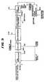
- Figure 2is a schematic diagram of an embodiment of the methanol synthesis and combustion turbine sections of an IGCC power plant according to the present invention.
- Figure 3is a plot of methanol productivity for a typical liquid-phase run without water addition.
- Figure 4is a plot of methanol productivity for a run with intermittent water addition.
- Figures 5 and 6are block flow diagrams for a simple once-through liquid-phase methanol IGCC process.
- Figure 5shows the process without water addition and Figure 6 with water addition.
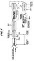
- Figures 7 and 8are block flow diagrams for a once-through liquid-phase methanol IGCC process with a membrane recycle.
- Figure 7shows the process without water addition and Figure 8 with water addition.
- Figures 9 and 10show block flow diagrams for a once-through liquid-phase methanol IGCC process with a membrane unit and a gas-phase methanol synthesis loop.
- Figure 9shows the process without water addition and Figure 10 with water addition.
- the present inventionis an improvement to the methanol production step within an integrated gasification combined cycle process wherein methanol is produced for peak-shaving from CO-rich synthesis gas.
- the improvement to the processis the combination of the methanol synthesis and water-gas shift reactions in a single step in order to increase methanol productivity.
- the improvement of the present inventionreplaces the need to balance the synthesis gas in shift and CO2 removal steps prior to its conversion to methanol as would be required if a gas-phase methanol synthesis process were used.
- the present inventionis based on the fact that if water is added to the CO-rich syngas feed to a liquid-phase methanol reactor, the water-gas shift and methanol synthesis reactions will take place simultaneously. In fact, if no water is added the reverse water-gas shift reaction is known to take place in either liquid or gas-phase reactors. The addition of water simply forces the equilibrium in the forward direction (i.e., CO + H2O ⁇ H2 + CO2).
- liquid watercan be added directly to the liquid-phase reactor. This saves the cost of generating high-pressure process steam, and also reduces the net heat which must be removed from the reactor.
- a conventional gas-phase reactorcannot accept a liquid water feed because thermal shock and rapid vaporization can break up and destroy the catalyst tablets.
- water vapor which is addedmust be kept well above its dew point to prevent condensation and subsequent quenching of the bed due to its plug flow operation.
- FIG. 1shows the effect of water, expressed as the molar H2O/CO ratio entering the liquid-phase methanol reactor, on methanol productivity (mmol MeOH/hr-gm catalyst) and on the molar H2/CO ratio (a measurement of the extent of the water-gas shift reaction) leaving the liquid-phase methanol reactor.
- This graphillustrates two important points. First, the methanol productivity curve goes through a maximum, showing that water indeed can be used to boost methanol productivity. This maximum was not seen or even suspected in the data reported in EPRI Report AF-1291. Second, adding water increases the hydrogen content in the effluent.
- the proposed IGCC coproduct plant flowsheet according to the present inventionis shown in Figure 2.
- desulfurized CO-rich synthesis gas and waterare fed to the process via lines 1 and 3, respectively, combined, and fed to liquid-phase reactor 7 via line 5, wherein the synthesis gas and water react in the presence of a catalyst.
- the liquid water or steam, in line 3can be added directly to reactor 7 without first being combined with the synthesis gas.
- Liquid-phase methanol reactor 7can be operated in either a slurry or ebullated mode.
- a powdered methanol synthesis catalyste.g., CuO/ZnO/Al2O3
- a liquid mediume.g. light paraffinic or cycloparaffinic oils
- a mixture of powdered methanol synthesis catalyst and low temperature shift catalystcan be used in reactor 7.
- the concentration of catalystcan range from about 5 to 50 wt%.
- a granulated catalystis fluidized in a liquid medium.
- Liquid-phase reactor 7operates within the conventional understanding of a liquid-phase reactor.
- the effluent removed via line 9 from liquid-phase reactor 7is cooled in a series of heat exchangers, including heat exchanger 43, and subsequently separated in separator 11 into a liquid and vapor stream.
- the primary purpose of separator 11is to recover and recycle the liquid medium which was vaporized and entrained in the reactor effluent.
- the liquid streamis recycled via line 13 to liquid-phase reactor 7. Additionally, to provide heat removal from reactor 7, a liquid stream is removed from the reactor via line 15, cooled and returned to reactor 7.
- the vapor stream from oil separator 11is removed via line 17 cooled in a series of heat exchangers so as to condense methanol and water in the stream and then fed to high pressure methanol separator 19.
- the overhead from separator 19is removed via line 21; this overhead is mainly unreacted synthesis gas, which is then reduced in pressure in expander 23 to recover power and subsequently fed to burner 49 via line 25.
- the liquid phase from separator 19is removed via line 27, reduced in pressure in J-T valve 29 and fed to low pressure methanol separator 31.
- separator 31dissolved synthesis gas in the methanol and water solution is removed as overhead via line 35 and fed as feed to burner 49.
- the bottoms of separator 31is removed via line 33 as crude methanol product.
- the combustion portion of the IGCC cycleis as follows: As mentioned earlier, the unreacted synthesis gas from the methanol synthesis portion is fed to burner 49 via lines 25 and 35. These streams are combusted in burner 49 along with fuel gas produced from the sulfur removal step of the gasifier portion of an IGCC facility (fed via line 81), compressed air and steam. The compressed air is introduced to the process via line 75, compressed in compressor 77 and introduced into the burner via line 79. Steam is produced and introduced into the burner through two heat sources. First, boiler feed water, in line 41, is heated in heat exchanger 43 against the effluent, line 9, from liquid-phase reactor 7 producing steam in line 45. Second, boiler feed water, in line 61, is heated in heat recovery unit 57 producing steam in line 63. These two steam streams, lines 45 and 63 are combined into stream 47 which is then fed to burner 49.
- the combustion gas from burner 49is fed to gas turbine expander 53 via line 51 for recovery of power and subsequently fed to heat recovery unit 57 via line 55.
- heat recovery unit 57energy is recovered from the expanded combustion gas by producing steam and superheating steam by heat exchange of the combustion gas with boiler feed water and saturated steam.
- a portion of the steam produced in heat recovery unit 57is introduced as feed to burner 49.
- the remaining portion of steam, in line 67, which is produced from boiler feed water introduced via line 65,is expanded in turbine 69 producing both power and low pressure steam.
- Stream 5is fed to liquid-phase reactor 7, which typically operates at about 249,2°C (482°F) and 62,7 bars (910 psia). Reaction heat is removed in an external heat exchange loop which produces saturated steam. The reactor effluent is cooled by first producing steam, then by heat exchange with unreacted fuel gas, and finally with cooling water. The two-phase mixture is separated and the vapor is heated and expanded, producing electric power.
- This expanded fuel gasis then sent to the gas turbine burner.
- the condensed methanolis flashed to yield the crude methanol product and a residual gas stream which is also fed to the gas turbine burner.
- the gas turbine burneralso receives a fuel gas stream from the upstream sulfur removal plant (e.g., Selexol, Rectisol, Rectisol II), sufficient steam from the process to control NO x production, and compressed air.
- the combustion zonetypically operates at 1092,2°C (2000°F).
- the burner effluentexpands across the gas turbine expander, which produces electric power for export and for running the air compressor.
- the gas turbine exhaustis used to produce and superheat steam in an integrated heat recovery system. The steam subsequently powers steam turbines which produce additional electric power.
- An IGCC coproduct plant without water additionhas two principal modes of operation. During peak power demand times, all of the fuel gas and some stored methanol go to the gas turbine. During off-peak hours, gas flows through the liquid-phase reactor to convert a portion of the gas to methanol for storage. With water addition, the methanol productivity per mass of catalyst is increased, which means that either the reactor can be downsized or additional methanol can be produced from a base-size unit. The plant has greater flexibility because it can operate in three modes: all fuel gas to the gas turbine, gas through the liquid-phase reactor without water addition, and gas through liquid-phase reactor with water added.
- Figure 3shows methanol productivity for a typical liquid-phase run with balanced syngas without water addition. Productivity falls off with time onstream from around 17 to 12.5 gmole/hr-kg.
- Figure 3illustrates the expected and well-known fact that methanol synthesis catalyst deactivates with time.
- Figure 3also illustrates a characteristic of methanol synthesis catalyst life curves, in that there is an early period of hyperactivity during which the catalyst deactivates sharply; after this hyperactivity period the catalyst deactivates slowly.
- Figure 4shows methanol productivity for a run with CO-rich syngas and intermittent water addition.
- Curve #1shows the baseline methanol productivity trend when water is added as indicated by curve #2.
- the data pointsrepresent the methanol productivity during the periods without water addition; the productivity during periods with water addition always exceed the baseline curve #1.
- curve #1is flat, rather than downward sloping, indicating that methanol productivity is not decreasing as was seen in Figure 3. This is especially notable because the comparison is made during the hyperactivity period, when the rate of deactivation is most pronounced. Therefore, Figure 4 indicates that the methanol productivity of the catalyst is preserved by the intermittent addition of water.
- the IGCC coproduction plant with water additionnot only gets an additional degree of flexibility and a smaller reactor or incremental methanol production, but also a longer-lived catalyst.
- Figures 5 and 6show block flow diagrams for a simple once-through liquid-phase methanol IGCC process.
- Figure 5shows the process without water addition and Figure 6 with water addition.
- the corresponding material balances for 3,000 TPD of low sulfur coal for each figureare shown in Tables I and II, respectively.
- Figures 7 and 8show block flow diagrams for a once-through liquid-phase methanol IGCC process with a membrane recycle.
- Figure 7shows the process without water addition and Figure 8 with water addition.
- the corresponding material balances for 3,000 TPD of low sulfur coal for each figureare shown in Tables III and IV, respectively.
- membrane material in this exampleis a commercially available cellulose acetate.
- Other membranes with higher H2/CO2 selectivitieswill permit even greater increases in methanol production.
- Figures 9 and 10show block flow diagrams for a once-through liquid-phase methanol IGCC process with a membrane unit and a gas-phase methanol synthesis loop.
- Figure 9shows the process without water addition and Figure 10 with water addition.
- the corresponding material balances for 3,000 TPD of low sulfur coal for each figureare shown in Tables V and VI, respectively.
- the H2O/CO ratiois slightly higher than in Examples I and II to facilitate sufficient water-gas shift reaction to give a balanced syngas after membrane processing.
- the membrane materialis cellulose acetate.
- Other membranes with higher H2/CO2 selectivitywould provide additional benefits by reducing the load on the CO2 removal unit and making more high pressure CO2 available for power recovery in the gas turbine expander.
- Figure 8shows a proposed block flow diagram for a plant which incorporates a membrane loop into the effluent fuel gas stream to recover hydrogen for recycle to the liquid-phase reactor.
- the recycled hydrogenincreases the feed H2/CO ratio to the reactor, which increases methanol production.
- the membranecan be used in conjunction with water addition to the liquid-phase methanol reactor, or without water addition. Mass and energy balances indicate that daily methanol production can be increased by 53% by using the membrane alone, and by an additional 15% by using both the membrane and water addition.
- Figure 10shows a proposed block flow diagram for an IGCC coproduction scheme which incorporates water addition, membrane H2 recovery, and a gas-phase methanol loop.
- a portion of the fuel gasbypasses the membrane so that, after CO2 removal from this stream and the membrane effluent, the combined stream is balanced.
- This balanced gasis fed to a conventional gas-phase methanol reactor, after which the methanol is recovered and the unreacted purge gas is sent to the gas turbine.
- Table VIIitemizes the relative methanol production which can be achieved in these various IGCC coproduct configurations. As seen, there are a total of 6 options available. Clearly there is significant flexibility available through practicing this invention. TABLE VII RELATIVE METHANOL PRODUCTION FOR IGCC COPRODUCT PLANT VARIATIONS USING COMBINED SHIFT/SYNTHESIS Option Methanol Production Compared to Option #1 1. Once Through Liquid-Phase Methanol 100% 2. With Water Addition 108% 3. With Membrane Recycle 153% 4. With Membrane Recycle and Water Addition 168% 5. With Membrane Recycle Gas-Phase MeOH Loop 188% 6. With Membrane Recycle Gas-Phase MeOH Loop and Water Addition 232%
Landscapes
- Chemical & Material Sciences (AREA)
- Engineering & Computer Science (AREA)
- Organic Chemistry (AREA)
- Combustion & Propulsion (AREA)
- Mechanical Engineering (AREA)
- General Engineering & Computer Science (AREA)
- Organic Low-Molecular-Weight Compounds And Preparation Thereof (AREA)
- Engine Equipment That Uses Special Cycles (AREA)
Description
- The present invention relates to an integrated gasification combined cycle (IGCC) process. More specifically, the present invention relates to an improvement which converts a portion of the produced, CO-rich synthesis gas to produce a crude methanol product for peak-shaving.
- Methanol is produced from synthesis gas (syngas), a mixture of hydrogen (H₂), carbon monoxide (CO), and carbon dioxide (CO₂). The stoichiometry of the methanol synthesis reactions indicates that the desired molar reactor feed composition is given by the equation:
R = (H₂-CO₂)/(CO+CO₂) = 2.0
However, reaction kinetics and system control dictate that the optimum ratio is actually R = 2.1 or higher. Gas with R = 2.0 to 2.1 is called "balanced" gas, i.e. balanced stoichiometrically, and has a typical composition of 19% CO, 5% CO₂, 55% H₂, and 21% CH₄-N₂. - Syngas is commonly made by the reforming of methane or other hydrocarbons, which gives a hydrogen-rich gas well-suited for methanol synthesis (e.g., a typical methanol syngas produced by steam reforming of methane has a composition of 15% CO, 8% CO₂, 73% H₂, 4% CH₄-N₂, R=2.8). Currently 70 to 75% of the world's methanol comes from reformed natural gas, however, because of the instability of the oil market, liquid hydrocarbons and natural gas are not always readily available or available at an inexpensive cost. An alternative and abundant resource is coal, which can be converted to syngas in a coal gasifier such as the advanced, high-temperature coal gasifiers developed by Texaco, Dow, Shell, and British Gas/Lurgi.
- Coal-derived syngas can be used as gas turbine fuel in an integrated gasification combined cycle (IGCC) electric power plant. Because of the daily cyclical demand for power, a primary concern in such a facility is load-following flexibility. To accomplish this flexibility, either the front end of the IGCC plant must be built for peak capacity, or extra fuel must be imported during peak periods (called peak shaving). The former is an expensive and inefficient option. The latter, although somewhat less expensive, can be improved by producing and storing the fuel on-site. One solution to this problem is the on-site production of methanol as the peak-shaving fuel.
- In an IGCC facility without methanol coproduction, the syngas is combusted in a gas turbine to produce electricity. The turbine exhaust/stack gas is used to generate and superheat steam in an integrated heat recovery system, and this steam is also used to generate electricity. In a coproduction facility, the syngas is first passed through a methanol synthesis reactor to convert a portion to methanol; the remaining syngas is fed to the gas turbine for power production. The methanol is stored as peak-shaving fuel, which is used to augment the feed to the gas turbine during periods of high power demand. This scheme is attractive because the load on a power plant varies over a wide range, and it is more economical to feed the stored methanol than to build peak-shaving capacity into the front end of the facility.
- Unfortunately, coal-derived syngas from advanced gasifiers used in IGCC plants is CO-rich (e.g., a Texaco gasifier syngas has a typical composition of 35% H₂, 51% CO, 13% CO₂, 1% CH₄-N₂; R=0.34), unlike the hydrogen-rich syngas from reformed hydrocarbons. The problem is that converting this gas to methanol by conventional methods is expensive and complicated because several pretreatment steps are required to balance the gas prior to methanol synthesis.
- Conceptual IGCC coproduct plants have been designed with gas-phase and with liquid-phase methanol synthesis reactors. With a gas-phase reactor, the main syngas stream from the gasifier is divided into two parts: approximately 75% goes directly to the gas turbine, and the remaining 25% goes to the methanol synthesis section. This latter stream is further divided, approximately 67% being mixed with steam and sent to a high temperature shift reactor (HTS). After shift, the CO₂ is removed and this stream is remixed with the unshifted stream and recycle gas in the methanol loop to give a balanced gas for methanol synthesis. Purge gas from the recycle loop and the rejected CO₂ from the CO₂ removal section are sent to the gas turbine. The use of a conventional, gas-phase methanol synthesis reactor in an IGCC coproduct scheme is subject to the same shortcomings as in a gas-phase all-methanol product plant: a shift section and CO₂ removal section are required in order to achieve a feed gas composition with an "R" value greater than 2.0, shift and methanol synthesis are performed in separate vessels, and the conversion per pass is limited by temperature constraints.
- The liquid-phase methanol process has an advantage over gas-phase methanol synthesis in a coproduct configuration because of its ability to directly process CO-rich gas (e.g., "R" values between about 0.30 and 0.40). The entire CO-rich gas stream from the gasifier is sent through the liquid-phase reactor in a single pass, achieving 10-20% conversion of CO to methanol. While additional methanol can be produced by balancing the gas prior to feeding it to the liquid-phase methanol reactor, the value of this incremental methanol is outweighed by the cost of separate shift and CO₂ removal units. Because a liquid-phase methanol reactor operates isothermally, there is no increasing catalyst temperature and the accompanying constraint on methanol conversion which is characteristic of gas-phase methanol synthesis processes. In a typical liquid-phase design, approximately 14% of the CO (feedgas "R" = 0.34) is converted to methanol, giving a reactor effluent containing approximately 9% methanol; the per pass conversion in a gas-phase reactor generally results in a reactor effluent containing only 5% methanol even though the feedgas has an "R" greater than 2.0. It should be noted, however, that even with the superior performance of the liquid-phase reactor, the coproduction scheme can still be expensive, and there is incentive to improve this processing route.
- A somewhat similar coproduction scheme is also worthy of mention (U.S. Pat. 3,986,349 and 4,092,825). This scheme involves converting coal-derived syngas into liquid hydrocarbons via Fischer-Tropsch synthesis, separating the hydrocarbons from the unreacted gas, feeding the gas to a gas turbine to generate electric power, and using at least part of the hydrocarbons as peak-shaving fuel. Although methanol is mentioned as a possible by-product of the hydrocarbon synthesis, it is not one of the desired products.
- The present invention is an improvement to an integrated gasification combined cycle (IGCC) electric power plant process. The IGCC process converts hydrocarbon fuels in a gasifier producing a CO-rich synthesis gas, which in turn is combusted in a gas turbine to produce power. The IGCC process also includes a provision for production of methanol from the CO-rich synthesis gas prior to combustion as a supplemental fuel, which can be used to peak-shave. Methanol is produced by reacting at least a portion of the CO-rich synthesis gas in the presence of a methanol synthesis catalyst.
- The improvement for increasing methanol productivity from the same amount of synthesis gas is the combination of the water/gas shift and methanol synthesis reactions in a single step by reacting the carbon monoxide-rich synthesis gas with water in the presence of a catalyst in a liquid-phase reactor thereby producing both a crude methanol product and a reduced carbon monoxide content and increased hydrogen and carbon dioxide content synthesis gas. The produced reduced carbon monoxide content and increased hydrogen and carbon dioxide content synthesis gas is suitable for combustion in a gas turbine.
- The water added to the liquid-phase reactor can be beneficially introduced as a liquid. The catalyst in the liquid-phase reactor can be any appropriate methanol synthesis catalyst or a mixture of a methanol synthesis catalyst and a low temperature shift catalyst. The catalyst concentration in the liquid-phase methanol reactor can be in the range from about 5 to about 50 weight percent. The improvement to the process of the present invention is particularly suited to CO-rich synthesis gases having an R value less than 2.0.
- The present invention also comprises several further processing steps. Among these are (1) processing at least a portion of the reduced carbon monoxide and increased hydrogen and carbon dioxide synthesis gas in, for example, a membrane unit or a pressure swing adsorber (PSA) unit to separate the reduced carbon monoxide and increased hydrogen and carbon dioxide synthesis gas into a hydrogen-rich component and a carbon monoxide-rich component, both components comprising hydrogen, carbon dioxide and carbon monoxide, and recycling the hydrogen rich component to the inlet of the liquid-phase reactor; and (2) processing at least a portion of the reduced carbon monoxide and increased hydrogen and carbon dioxide synthesis gas in, for example, a membrane unit or a pressure swing adsorber (PSA) unit to separate the reduced carbon monoxide and increased hydrogen and carbon dioxide synthesis gas into a hydrogen-rich component and a carbon monoxide-rich component, both components comprising hydrogen, carbon dioxide and carbon monoxide, combining the hydrogen-rich component and a portion of the unprocessed synthesis gas (i.e., the gas not processed in the membrane or PSA units) into a single methanol reactor feed stream, optionally removing at least a portion of the carbon dioxide from the gas-phase methanol reactor feed stream, reacting the methanol reactor feed stream in a gas-phase reactor to produce methanol, and combining the unconverted effluent from the gas-phase methanol reactor with the carbon monoxide-rich component from the membrane unit to form a gas turbine combustion feed.
- Figure 1 is a plot showing the effect of water, expressed as molar H₂O/CO ratio entering the liquid-phase methanol reactor, on methanol productivity and on the hydrogen content leaving the liquid-phase methanol reactor.
- Figure 2 is a schematic diagram of an embodiment of the methanol synthesis and combustion turbine sections of an IGCC power plant according to the present invention.
- Figure 3 is a plot of methanol productivity for a typical liquid-phase run without water addition.
- Figure 4 is a plot of methanol productivity for a run with intermittent water addition.
- Figures 5 and 6 are block flow diagrams for a simple once-through liquid-phase methanol IGCC process. Figure 5 shows the process without water addition and Figure 6 with water addition.
- Figures 7 and 8 are block flow diagrams for a once-through liquid-phase methanol IGCC process with a membrane recycle. Figure 7 shows the process without water addition and Figure 8 with water addition.
- Figures 9 and 10 show block flow diagrams for a once-through liquid-phase methanol IGCC process with a membrane unit and a gas-phase methanol synthesis loop. Figure 9 shows the process without water addition and Figure 10 with water addition.
- The present invention is an improvement to the methanol production step within an integrated gasification combined cycle process wherein methanol is produced for peak-shaving from CO-rich synthesis gas. The improvement to the process is the combination of the methanol synthesis and water-gas shift reactions in a single step in order to increase methanol productivity. The improvement of the present invention replaces the need to balance the synthesis gas in shift and CO₂ removal steps prior to its conversion to methanol as would be required if a gas-phase methanol synthesis process were used. The present invention is based on the fact that if water is added to the CO-rich syngas feed to a liquid-phase methanol reactor, the water-gas shift and methanol synthesis reactions will take place simultaneously. In fact, if no water is added the reverse water-gas shift reaction is known to take place in either liquid or gas-phase reactors. The addition of water simply forces the equilibrium in the forward direction (i.e., CO + H₂O → H₂ + CO₂).
- Several advantages of the liquid-phase methanol reactor have already been mentioned. An additional advantage is seen when considering water addition. In contrast to conventional technologies, liquid water can be added directly to the liquid-phase reactor. This saves the cost of generating high-pressure process steam, and also reduces the net heat which must be removed from the reactor. A conventional gas-phase reactor cannot accept a liquid water feed because thermal shock and rapid vaporization can break up and destroy the catalyst tablets. In addition, water vapor which is added must be kept well above its dew point to prevent condensation and subsequent quenching of the bed due to its plug flow operation.
- Although the addition of steam to a liquid-phase methanol reactor was considered in EPRI Report AF-1291 (December 1979, p. 5-3), wherein the concept is discussed, and laboratory data is presented for two syngas compositions, the data indicated that methanol productivity decreases as water is added. It was reported that water additionalways reduces methanol productivity, especially for gases that already have the required H₂/CO stoichiometry, and that for non-stoichiometric synthesis gases, the fall off in productivity with increasing steam/CO ratio is slower.
- The experimentation behind the present invention, on the other hand, shows results which are surprising relative to those in the EPRI report. Figure 1 shows the effect of water, expressed as the molar H₂O/CO ratio entering the liquid-phase methanol reactor, on methanol productivity (mmol MeOH/hr-gm catalyst) and on the molar H₂/CO ratio (a measurement of the extent of the water-gas shift reaction) leaving the liquid-phase methanol reactor. This graph illustrates two important points. First, the methanol productivity curve goes through a maximum, showing that water indeed can be used to boost methanol productivity. This maximum was not seen or even suspected in the data reported in EPRI Report AF-1291. Second, adding water increases the hydrogen content in the effluent. Although the CO₂ produced from the shift reaction prevents a stoichiometrically balanced effluent, the proper amount of CO₂ can be removed later to give a balanced gas, if desired. Thus, adding a precise amount of water results in increased methanol production relative to dry CO-rich gas feed as well as a notable production of H₂ via the shift reaction. Adding more water results in increased H₂ production at some sacrifice to methanol productivity.
- The proposed IGCC coproduct plant flowsheet according to the present invention is shown in Figure 2. With reference to Figure 2, desulfurized CO-rich synthesis gas and water (liquid or vapor) are fed to the process via
lines phase reactor 7 vialine 5, wherein the synthesis gas and water react in the presence of a catalyst. Alternatively, the liquid water or steam, inline 3, can be added directly toreactor 7 without first being combined with the synthesis gas. Liquid-phase methanol reactor 7 can be operated in either a slurry or ebullated mode. In the case of the slurry mode, a powdered methanol synthesis catalyst (e.g., CuO/ZnO/Al₂O₃) is slurried in a liquid medium (e.g. light paraffinic or cycloparaffinic oils). Alternatively, a mixture of powdered methanol synthesis catalyst and low temperature shift catalyst can be used inreactor 7. The concentration of catalyst can range from about 5 to 50 wt%. In the case of an ebullated mode, a granulated catalyst is fluidized in a liquid medium. Liquid-phase reactor 7 operates within the conventional understanding of a liquid-phase reactor. - The effluent removed via
line 9 from liquid-phase reactor 7 is cooled in a series of heat exchangers, includingheat exchanger 43, and subsequently separated inseparator 11 into a liquid and vapor stream. The primary purpose ofseparator 11 is to recover and recycle the liquid medium which was vaporized and entrained in the reactor effluent. The liquid stream is recycled vialine 13 to liquid-phase reactor 7. Additionally, to provide heat removal fromreactor 7, a liquid stream is removed from the reactor vialine 15, cooled and returned toreactor 7. - The vapor stream from
oil separator 11 is removed vialine 17 cooled in a series of heat exchangers so as to condense methanol and water in the stream and then fed to highpressure methanol separator 19. The overhead fromseparator 19 is removed vialine 21; this overhead is mainly unreacted synthesis gas, which is then reduced in pressure inexpander 23 to recover power and subsequently fed toburner 49 vialine 25. - The liquid phase from
separator 19 is removed vialine 27, reduced in pressure in J-T valve 29 and fed to lowpressure methanol separator 31. Inseparator 31, dissolved synthesis gas in the methanol and water solution is removed as overhead vialine 35 and fed as feed toburner 49. The bottoms ofseparator 31 is removed vialine 33 as crude methanol product. - The above is a description of a once through methanol synthesis portion of an IGCC process. The combustion portion of the IGCC cycle is as follows: As mentioned earlier, the unreacted synthesis gas from the methanol synthesis portion is fed to
burner 49 vialines burner 49 along with fuel gas produced from the sulfur removal step of the gasifier portion of an IGCC facility (fed via line 81), compressed air and steam. The compressed air is introduced to the process vialine 75, compressed incompressor 77 and introduced into the burner vialine 79. Steam is produced and introduced into the burner through two heat sources. First, boiler feed water, inline 41, is heated inheat exchanger 43 against the effluent,line 9, from liquid-phase reactor 7 producing steam inline 45. Second, boiler feed water, inline 61, is heated inheat recovery unit 57 producing steam inline 63. These two steam streams,lines stream 47 which is then fed toburner 49. - The combustion gas from
burner 49 is fed togas turbine expander 53 vialine 51 for recovery of power and subsequently fed to heatrecovery unit 57 vialine 55. Inheat recovery unit 57, energy is recovered from the expanded combustion gas by producing steam and superheating steam by heat exchange of the combustion gas with boiler feed water and saturated steam. A portion of the steam produced inheat recovery unit 57 is introduced as feed toburner 49. The remaining portion of steam, inline 67, which is produced from boiler feed water introduced via line 65, is expanded inturbine 69 producing both power and low pressure steam. - In the above description,
stream 1 represents desulfurized CO-rich gas from a Texaco coal gasifier;stream 3 can be used to supply water such that the combined streams (line 5) have a molar ratio of H₂O/CO = 0.17. As shown in Figure 1, this is approximately the ratio necessary to achieve the maximum methanol production.Stream 5 is fed to liquid-phase reactor 7, which typically operates at about 249,2°C (482°F) and 62,7 bars (910 psia). Reaction heat is removed in an external heat exchange loop which produces saturated steam. The reactor effluent is cooled by first producing steam, then by heat exchange with unreacted fuel gas, and finally with cooling water. The two-phase mixture is separated and the vapor is heated and expanded, producing electric power. This expanded fuel gas is then sent to the gas turbine burner. The condensed methanol is flashed to yield the crude methanol product and a residual gas stream which is also fed to the gas turbine burner. In addition to the main fuel gas and flash gas streams, the gas turbine burner also receives a fuel gas stream from the upstream sulfur removal plant (e.g., Selexol, Rectisol, Rectisol II), sufficient steam from the process to control NOx production, and compressed air. These streams are fed to the combustion zone, which typically operates at 1092,2°C (2000°F). The burner effluent expands across the gas turbine expander, which produces electric power for export and for running the air compressor. The gas turbine exhaust is used to produce and superheat steam in an integrated heat recovery system. The steam subsequently powers steam turbines which produce additional electric power. - An IGCC coproduct plant without water addition has two principal modes of operation. During peak power demand times, all of the fuel gas and some stored methanol go to the gas turbine. During off-peak hours, gas flows through the liquid-phase reactor to convert a portion of the gas to methanol for storage. With water addition, the methanol productivity per mass of catalyst is increased, which means that either the reactor can be downsized or additional methanol can be produced from a base-size unit. The plant has greater flexibility because it can operate in three modes: all fuel gas to the gas turbine, gas through the liquid-phase reactor without water addition, and gas through liquid-phase reactor with water added.
- An additional, surprising benefit of water addition has been demonstrated in the laboratory. Figure 3 shows methanol productivity for a typical liquid-phase run with balanced syngas without water addition. Productivity falls off with time onstream from around 17 to 12.5 gmole/hr-kg. Figure 3 illustrates the expected and well-known fact that methanol synthesis catalyst deactivates with time. Figure 3 also illustrates a characteristic of methanol synthesis catalyst life curves, in that there is an early period of hyperactivity during which the catalyst deactivates sharply; after this hyperactivity period the catalyst deactivates slowly.
- Figure 4 shows methanol productivity for a run with CO-rich syngas and intermittent water addition.
Curve # 1 shows the baseline methanol productivity trend when water is added as indicated bycurve # 2. The data points represent the methanol productivity during the periods without water addition; the productivity during periods with water addition always exceed thebaseline curve # 1. The important point here is thatcurve # 1 is flat, rather than downward sloping, indicating that methanol productivity is not decreasing as was seen in Figure 3. This is especially notable because the comparison is made during the hyperactivity period, when the rate of deactivation is most pronounced. Therefore, Figure 4 indicates that the methanol productivity of the catalyst is preserved by the intermittent addition of water. Thus, the IGCC coproduction plant with water addition not only gets an additional degree of flexibility and a smaller reactor or incremental methanol production, but also a longer-lived catalyst. - In order to further demonstrate the efficacy of the present invention and to provide a description of several other process steps which can make the IGCC process more flexible, the following examples were simulated. In these examples a base case without water addition has been run for each of the process configurations.
- Figures 5 and 6 show block flow diagrams for a simple once-through liquid-phase methanol IGCC process. Figure 5 shows the process without water addition and Figure 6 with water addition. The corresponding material balances for 3,000 TPD of low sulfur coal for each figure are shown in Tables I and II, respectively.


- Figures 7 and 8 show block flow diagrams for a once-through liquid-phase methanol IGCC process with a membrane recycle. Figure 7 shows the process without water addition and Figure 8 with water addition. The corresponding material balances for 3,000 TPD of low sulfur coal for each figure are shown in Tables III and IV, respectively.
- It should be noted that the membrane material in this example is a commercially available cellulose acetate. Other membranes with higher H₂/CO₂ selectivities will permit even greater increases in methanol production.


- Figures 9 and 10 show block flow diagrams for a once-through liquid-phase methanol IGCC process with a membrane unit and a gas-phase methanol synthesis loop. Figure 9 shows the process without water addition and Figure 10 with water addition. The corresponding material balances for 3,000 TPD of low sulfur coal for each figure are shown in Tables V and VI, respectively.
- In this example, the H₂O/CO ratio is slightly higher than in Examples I and II to facilitate sufficient water-gas shift reaction to give a balanced syngas after membrane processing. As in Example II, the membrane material is cellulose acetate. Other membranes with higher H₂/CO₂ selectivity would provide additional benefits by reducing the load on the CO₂ removal unit and making more high pressure CO₂ available for power recovery in the gas turbine expander.


- As can be seen from the Examples, the present invention includes several other process variations which add even more flexibility to the IGCC coproduction flowsheet. Figure 8 shows a proposed block flow diagram for a plant which incorporates a membrane loop into the effluent fuel gas stream to recover hydrogen for recycle to the liquid-phase reactor. The recycled hydrogen increases the feed H₂/CO ratio to the reactor, which increases methanol production. The membrane can be used in conjunction with water addition to the liquid-phase methanol reactor, or without water addition. Mass and energy balances indicate that daily methanol production can be increased by 53% by using the membrane alone, and by an additional 15% by using both the membrane and water addition.
- Figure 10 shows a proposed block flow diagram for an IGCC coproduction scheme which incorporates water addition, membrane H₂ recovery, and a gas-phase methanol loop. Here, a portion of the fuel gas bypasses the membrane so that, after CO₂ removal from this stream and the membrane effluent, the combined stream is balanced. This balanced gas is fed to a conventional gas-phase methanol reactor, after which the methanol is recovered and the unreacted purge gas is sent to the gas turbine.
- Table VII itemizes the relative methanol production which can be achieved in these various IGCC coproduct configurations. As seen, there are a total of 6 options available. Clearly there is significant flexibility available through practicing this invention.
TABLE VII RELATIVE METHANOL PRODUCTION FOR IGCC COPRODUCT PLANT VARIATIONS USING COMBINED SHIFT/SYNTHESIS Option Methanol Production Compared to Option # 11. Once Through Liquid- Phase Methanol 100% 2. With Water Addition 108% 3. With Membrane Recycle 153% 4. With Membrane Recycle and Water Addition 168% 5. With Membrane Recycle Gas-Phase MeOH Loop 188% 6. With Membrane Recycle Gas-Phase MeOH Loop and Water Addition 232% - The present invention has been described with reference to a specific embodiment thereof. This embodiment should not be considered a limitation on the scope of the present invention; the scope of which should be ascertained by the following claims.


Claims (11)
- In an integrated gasification combined cycle (IGCC) electric power plant process wherein the IGCC process converts hydrocarbon fuels in a gasifier producing a carbon monoxide-rich synthesis gas, which in turn is combusted in a gas turbine to produce power; wherein the IGCC process also includes a provision for production of methanol from the carbon monoxide-rich synthesis gas prior to combustion; and wherein methanol is produced by reacting at least a portion of the carbon monoxide-rich synthesis gas in the presence of a methanol synthesis catalyst; the improvement for increasing methanol productivity from the same amount of synthesis gas comprises combining water/gas shift and methanol synthesis reactions in a single step by reacting the carbon monoxide-rich synthesis gas with water in the presence of a catalyst in a liquid-phase reactor thereby producing both a crude methanol product and a reduced carbon monoxide content and increased hydrogen and carbon dioxide content synthesis gas for combustion.
- The process of Claim 1 wherein the carbon monoxide-rich synthesis gas has an "R" value of less than 2.0.
- The process of Claim 1 wherein the water reacted with the carbon monoxide-rich synthesis gas in the liquid-phase reactor is introduced to the reactor as liquid water.
- The process of Claim 1 wherein the catalyst in the liquid-phase reactor comprises a methanol synthesis catalyst.
- The process of Claim 1 wherein the catalyst in the liquid-phase reactor comprises a mixture of a methanol synthesis catalyst and a low temperature shift catalyst.
- The process of Claim 1 wherein concentration of the catalyst in the liquid-phase reactor is in the range from 5 to 50 weight percent.
- The process of Claim 1 which further comprises processing at least a portion of the reduced carbon monoxide and increased hydrogen and carbon dioxide synthesis gas to separate the reduced carbon monoxide and increased hydrogen and carbon dioxide synthesis gas into a hydrogen-rich component and a carbon monoxide-rich component, both components comprising hydrogen, carbon dioxide and carbon monoxide, and recycling the hydrogen rich component to the inlet of the liquid-phase reactor.
- The process of Claim 7 wherein separation of the reduced carbon monoxide and increased hydrogen and carbon dioxide synthesis gas is accomplished in a membrane unit.
- The process of Claim 1 which further comprises processing at least a portion of the reduced carbon monoxide and increased hydrogen and carbon dioxide synthesis gas to separate the reduced carbon monoxide and increased hydrogen and carbon dioxide synthesis gas into a hydrogen-rich component and a carbon monoxide-rich component, both components comprising hydrogen, carbon dioxide and carbon monoxide, combining the hydrogen-rich component and a portion of the unprocessed synthesis gas to form a gas-phase methanol reactor feed stream, reacting the gas-phase methanol reactor feed stream in a gas-phase reactor to produce methanol, and combining the unconverted effluent from the gas-phase methanol reactor with the carbon monoxide-rich component to form a gas turbine combustion feed.
- The process of Claim 9 which further comprises removing at least a portion of the carbon dioxide from the gas-phase methanol reactor feed stream prior to reacting the gas-phase methanol reactor feed stream in the gas-phase reactor to produce methanol.
- The process of Claim 10 wherein separation of the reduced carbon monoxide and increased hydrogen and carbon dioxide synthesis gas is accomplished in a membrane unit.
Applications Claiming Priority (2)
| Application Number | Priority Date | Filing Date | Title |
|---|---|---|---|
| US07/178,955US4946477A (en) | 1988-04-07 | 1988-04-07 | IGCC process with combined methanol synthesis/water gas shift for methanol and electrical power production |
| US178955 | 1988-04-07 |
Publications (3)
| Publication Number | Publication Date |
|---|---|
| EP0336378A2 EP0336378A2 (en) | 1989-10-11 |
| EP0336378A3 EP0336378A3 (en) | 1992-02-05 |
| EP0336378B1true EP0336378B1 (en) | 1994-01-05 |
Family
ID=22654604
Family Applications (1)
| Application Number | Title | Priority Date | Filing Date |
|---|---|---|---|
| EP89105906AExpired - LifetimeEP0336378B1 (en) | 1988-04-07 | 1989-04-04 | IGCC process with combined methanol synthesis/water gas shift for methanol and electrical power production |
Country Status (7)
| Country | Link |
|---|---|
| US (1) | US4946477A (en) |
| EP (1) | EP0336378B1 (en) |
| JP (1) | JPH01301925A (en) |
| AU (1) | AU612810B2 (en) |
| CA (1) | CA1330349C (en) |
| DE (1) | DE68911972T2 (en) |
| ES (1) | ES2061757T3 (en) |
Families Citing this family (59)
| Publication number | Priority date | Publication date | Assignee | Title |
|---|---|---|---|---|
| DE68904202T2 (en)* | 1988-01-14 | 1993-05-06 | Air Prod & Chem | ONE-STEP METHOD FOR SYNTHESIS OF DIMETHYLAETHER USING A LIQUID-PHASE REACTOR SYSTEM. |
| US5571483A (en)* | 1990-01-26 | 1996-11-05 | Exolon-Esk Company | System of converting environmentally pollutant waste gases to a useful product |
| US5232951A (en)* | 1990-01-26 | 1993-08-03 | Exolon-Esk Company | Method of converting environmentally pollutant waste gases to methanol |
| EP0445660A2 (en)* | 1990-03-07 | 1991-09-11 | Air Products And Chemicals, Inc. | Integrated production of methanol and electric power |
| US5179129A (en)* | 1991-03-01 | 1993-01-12 | Air Products And Chemicals, Inc. | Staged liquid phase methanol process |
| EP0550242B1 (en)* | 1991-12-30 | 1996-11-20 | Texaco Development Corporation | Processing of synthesis gas |
| DE69303631T2 (en)* | 1992-02-04 | 1996-12-12 | Air Prod & Chem | Production process of methanol in the liquid phase with recycling of a CO-rich gastrom |
| US5392594A (en)* | 1993-02-01 | 1995-02-28 | Air Products And Chemicals, Inc. | Integrated production of fuel gas and oxygenated organic compounds from synthesis gas |
| JP3149289B2 (en)* | 1993-03-24 | 2001-03-26 | 三菱製紙株式会社 | Image forming material and image forming method using the same |
| US6032456A (en)* | 1995-04-07 | 2000-03-07 | Lsr Technologies, Inc | Power generating gasification cycle employing first and second heat exchangers |
| US6313361B1 (en) | 1996-02-13 | 2001-11-06 | Marathon Oil Company | Formation of a stable wax slurry from a Fischer-Tropsch reactor effluent |
| US6201029B1 (en) | 1996-02-13 | 2001-03-13 | Marathon Oil Company | Staged combustion of a low heating value fuel gas for driving a gas turbine |
| US6130259A (en)* | 1996-02-13 | 2000-10-10 | Marathon Oil Company | Hydrocarbon gas conversion system and process for producing a synthetic hydrocarbon liquid |
| US5861441A (en)* | 1996-02-13 | 1999-01-19 | Marathon Oil Company | Combusting a hydrocarbon gas to produce a reformed gas |
| US5733941A (en)* | 1996-02-13 | 1998-03-31 | Marathon Oil Company | Hydrocarbon gas conversion system and process for producing a synthetic hydrocarbon liquid |
| AU740616B2 (en)* | 1996-06-21 | 2001-11-08 | Syntroleum Corporation | Synthesis gas production system and method |
| PE17599A1 (en) | 1996-07-09 | 1999-02-22 | Syntroleum Corp | PROCEDURE TO CONVERT GASES TO LIQUIDS |
| US5806298A (en)* | 1996-09-20 | 1998-09-15 | Air Products And Chemicals, Inc. | Gas turbine operation with liquid fuel vaporization |
| US5950732A (en)* | 1997-04-02 | 1999-09-14 | Syntroleum Corporation | System and method for hydrate recovery |
| US6160026A (en)* | 1997-09-24 | 2000-12-12 | Texaco Inc. | Process for optimizing hydrocarbon synthesis |
| JP3973772B2 (en)* | 1998-08-28 | 2007-09-12 | 株式会社東芝 | Coal gasification combined cycle power plant |
| NO310863B1 (en)* | 1999-11-19 | 2001-09-10 | Norske Stats Oljeselskap | Cogeneration of methanol and electric power |
| BR0206827B1 (en) | 2001-02-01 | 2012-05-02 | integrated processes for the production of hydrocarbon and energy products, and for the production of synthesis and energy gas. | |
| CA2357527C (en) | 2001-10-01 | 2009-12-01 | Technology Convergence Inc. | Methanol recycle stream |
| US7776208B2 (en)* | 2004-01-12 | 2010-08-17 | L'air Liquide - Societe Anonyme A Directoire Et Conseil De Surveillance Pour L'etude Et L'exploitation Des Procedes Georges Claude | Integration of gasification, hydrocarbon synthesis unit, and refining processes |
| US20060149423A1 (en)* | 2004-11-10 | 2006-07-06 | Barnicki Scott D | Method for satisfying variable power demand |
| DE102004058759A1 (en)* | 2004-11-30 | 2006-06-01 | Vattenfall Europe Generation Ag & Co. Kg | Method for providing a fuel for the gas turbine of an IGCC power plant |
| DE102004058760B4 (en)* | 2004-11-30 | 2011-08-18 | Vattenfall Europe Generation AG & Co. KG, 03050 | Method for operating a gas and steam turbine power plant with integrated coal gasification |
| CA2601445C (en) | 2005-03-16 | 2012-10-02 | Fuelcor Llc | Systems, methods, and compositions for production of synthetic hydrocarbon compounds |
| WO2007019643A1 (en) | 2005-08-19 | 2007-02-22 | Varipower Technology Pty Ltd | Method for generating power |
| US7503947B2 (en)* | 2005-12-19 | 2009-03-17 | Eastman Chemical Company | Process for humidifying synthesis gas |
| CA2637587A1 (en)* | 2006-01-17 | 2007-07-26 | Manufacturing And Technology Conversion International, Inc. | A hybrid energy conversion system and processes |
| US7739875B2 (en)* | 2006-08-07 | 2010-06-22 | General Electric Company | Syngas power systems and method for use thereof |
| US20090014689A1 (en)* | 2007-07-09 | 2009-01-15 | Range Fuels, Inc. | Methods and apparatus for producing syngas and alcohols |
| GB0715101D0 (en)* | 2007-08-03 | 2007-09-12 | Johnson Matthey Plc | Process |
| WO2009023132A1 (en)* | 2007-08-10 | 2009-02-19 | International Financial Services #1, Llc | Integrated process for carbonaceous material to co2-free fuel gas for power plants and biomass to ethanol |
| US20090038316A1 (en)* | 2007-08-10 | 2009-02-12 | International Financial Services #1, Llc | Integrated process for carbonaceous material to co2-free fuel gas for power plants and to ethylene |
| US20090173080A1 (en)* | 2008-01-07 | 2009-07-09 | Paul Steven Wallace | Method and apparatus to facilitate substitute natural gas production |
| US8528343B2 (en)* | 2008-01-07 | 2013-09-10 | General Electric Company | Method and apparatus to facilitate substitute natural gas production |
| US20090173081A1 (en)* | 2008-01-07 | 2009-07-09 | Paul Steven Wallace | Method and apparatus to facilitate substitute natural gas production |
| US8252091B2 (en)* | 2008-03-18 | 2012-08-28 | General Electric Company | CO2 recovery from IGCC power plants |
| US8398730B2 (en) | 2008-07-23 | 2013-03-19 | General Electric Company | Method and apparatus to facilitate substitute natural gas production |
| DE102008048062B3 (en)* | 2008-09-19 | 2010-04-08 | Forschungszentrum Jülich GmbH | IGCC power plant with flue gas recirculation and purge gas |
| US20100126135A1 (en)* | 2008-11-26 | 2010-05-27 | General Electric Company | Method and apparatus for operating an integrated gasifier power plant |
| US9328631B2 (en)* | 2009-02-20 | 2016-05-03 | General Electric Company | Self-generated power integration for gasification |
| GB0914500D0 (en)* | 2009-08-19 | 2009-09-30 | Johnson Matthey Plc | Process |
| ES2440016T3 (en)* | 2009-08-20 | 2014-01-27 | Saudi Basic Industries Corporation | Procedure for the co-production of methanol and ammonia |
| EP2322494B1 (en)* | 2009-11-17 | 2013-01-09 | Lurgi GmbH | Production of dimethyl ether from crude methanol |
| UY33038A (en)* | 2009-11-20 | 2011-06-30 | Rv Lizenz Ag | THERMAL AND CHEMICAL USE OF CABONACE SUBSTANCES IN PARTICULAR FOR THE GENERATION OF ENERGY WITHOUT EMISSIONS |
| JP5495749B2 (en) | 2009-12-10 | 2014-05-21 | 三菱重工業株式会社 | Hydrogen production facility and power plant |
| US8435326B2 (en)* | 2010-01-15 | 2013-05-07 | G.D.O. | Multi-stage process for removing CO2 relative to hydrogen from syngas streams |
| DE102010024429A1 (en) | 2010-06-21 | 2011-12-22 | Technische Universität München | Operating integrated gasification combined cycle power plant, comprises converting fuels in gasifier using adjuvants including oxygen, vapor, carbon dioxide and water, and cleaning raw gas from gasifier and treating gas in shift reactor |
| DE102010049801A1 (en) | 2010-10-27 | 2012-05-03 | Technische Universität München | Method for operating integrated gasification combined cycle of power station, involves post-treating carbon dioxide, where separation of carbon dioxide from exhaust gas is realized after burning process |
| US8567355B2 (en)* | 2010-12-22 | 2013-10-29 | Caterpillar Inc. | Integrated control system and method |
| CN109812335B (en)* | 2019-01-15 | 2021-11-16 | 中国石油大学(华东) | Zero-carbon-emission integrated coal gasification-steam combined cycle power generation process |
| US11149634B2 (en)* | 2019-03-01 | 2021-10-19 | Richard Alan Callahan | Turbine powered electricity generation |
| US11149636B2 (en)* | 2019-03-01 | 2021-10-19 | Richard Alan Callahan | Turbine powered electricity generation |
| EP3986829A1 (en) | 2019-06-18 | 2022-04-27 | Haldor Topsøe A/S | Methane rich gas upgrading to methanol |
| CN120379962A (en) | 2022-12-14 | 2025-07-25 | 巴斯夫欧洲公司 | For use with CO2Process for preparing at least one polyisocyanate |
Family Cites Families (14)
| Publication number | Priority date | Publication date | Assignee | Title |
|---|---|---|---|---|
| US2665289A (en)* | 1948-09-25 | 1954-01-05 | Hydrocarbon Research Inc | Catalytic synthesis of hydrocarbons |
| GB1595413A (en)* | 1976-12-15 | 1981-08-12 | Ici Ltd | Engergy recovery from chemical process off-gas |
| US4235800A (en)* | 1978-05-31 | 1980-11-25 | Imperial Chemical Industries Limited | Synthesis gas |
| US4239693A (en)* | 1979-06-22 | 1980-12-16 | Foster Wheeler Energy Corporation | Process for production of methanol |
| DE3028646A1 (en)* | 1980-07-29 | 1982-03-04 | Metallgesellschaft Ag, 6000 Frankfurt | METHOD FOR IMPROVING BALANCE AND SIMULTANEOUSLY GENERATING HIGH-PRESSURE STEAM IN THE PRODUCTION OF METHANOL |
| US4407973A (en)* | 1982-07-28 | 1983-10-04 | The M. W. Kellogg Company | Methanol from coal and natural gas |
| US4477594A (en)* | 1982-12-16 | 1984-10-16 | Chem Systems, Inc. | Process for the synthesis of aliphatic alcohol-containing mixtures |
| JPS59207827A (en)* | 1983-05-10 | 1984-11-26 | Ube Ind Ltd | Method for separating gas from gas mixture |
| GB2142331A (en)* | 1983-06-29 | 1985-01-16 | Toyo Engineering Corp | A process for producing methanol |
| US4650814A (en)* | 1984-03-07 | 1987-03-17 | Keller Arnold P | Process for producing methanol from a feed gas |
| CA1263671A (en)* | 1986-02-10 | 1989-12-05 | David Leon Banquy | Process for the production of synthesis gas |
| US4628066A (en)* | 1986-02-12 | 1986-12-09 | Air Products And Chemicals, Inc. | Process for the production of methanol |
| US4766154A (en)* | 1987-02-06 | 1988-08-23 | Air Products And Chemicals, Inc. | Liquid phase methanol reactor staging process for the production of methanol |
| AU3240689A (en)* | 1988-04-07 | 1989-10-12 | Air Products And Chemicals Inc. | Process using water addition for the conversion of co-rich synthesis gas to methanol |
- 1988
- 1988-04-07USUS07/178,955patent/US4946477A/ennot_activeExpired - Lifetime
- 1989
- 1989-03-31CACA000595444Apatent/CA1330349C/ennot_activeExpired - Fee Related
- 1989-04-04AUAU32404/89Apatent/AU612810B2/ennot_activeCeased
- 1989-04-04ESES89105906Tpatent/ES2061757T3/ennot_activeExpired - Lifetime
- 1989-04-04DEDE89105906Tpatent/DE68911972T2/ennot_activeExpired - Fee Related
- 1989-04-04EPEP89105906Apatent/EP0336378B1/ennot_activeExpired - Lifetime
- 1989-04-07JPJP1089526Apatent/JPH01301925A/enactivePending
Also Published As
| Publication number | Publication date |
|---|---|
| JPH01301925A (en) | 1989-12-06 |
| AU3240489A (en) | 1989-10-12 |
| EP0336378A2 (en) | 1989-10-11 |
| DE68911972T2 (en) | 1994-05-05 |
| US4946477A (en) | 1990-08-07 |
| CA1330349C (en) | 1994-06-21 |
| DE68911972D1 (en) | 1994-02-17 |
| EP0336378A3 (en) | 1992-02-05 |
| ES2061757T3 (en) | 1994-12-16 |
| AU612810B2 (en) | 1991-07-18 |
Similar Documents
| Publication | Publication Date | Title |
|---|---|---|
| EP0336378B1 (en) | IGCC process with combined methanol synthesis/water gas shift for methanol and electrical power production | |
| US5284878A (en) | Liquid phase methanol process with co-rich recycle | |
| US7919065B2 (en) | Apparatus and methods for the production of ammonia and Fischer-Tropsch liquids | |
| EP0283171B1 (en) | Production of fuel gas | |
| US5666800A (en) | Gasification combined cycle power generation process with heat-integrated chemical production | |
| US4524581A (en) | Method for the production of variable amounts of power from syngas | |
| US4407973A (en) | Methanol from coal and natural gas | |
| EP0723930B1 (en) | Gasification process combined with steam methane performing to produce syngas suitable for methanol production | |
| US8552073B2 (en) | Co-production of power and hydrocarbons | |
| US9145525B2 (en) | Acid gas management in liquid fuel production process | |
| EP1197471B1 (en) | A process and apparatus for the production of synthesis gas | |
| GB2078251A (en) | System for Gasifying Coal and Reforming Gaseous Products Thereof | |
| WO2007061616A1 (en) | Process for producing variable syngas compositions | |
| US4443560A (en) | Adiabatically reforming a reformed gas for producing methanol | |
| Zennaro et al. | Syngas: the basis of Fischer–Tropsch | |
| EP1597341B1 (en) | Improved process for shift conversion | |
| EP0445660A2 (en) | Integrated production of methanol and electric power | |
| EP0601886B1 (en) | Manufacture of organic liquids | |
| JPH0463913B2 (en) | ||
| EP0336440A2 (en) | Process using water addition for the conversion of co-rich synthesis gas to methanol | |
| Zennaro et al. | Syngas (a mixture of carbon monoxide and hydrogen) is normally made industri-ally from natural gas or coal. The ratio of H₂ to CO can be manipulated by the water-gas shift reaction (WGSR): CO+ H2O= CO2+ H2, AH=+ 41 kJ/mol Since the WGSR is reversible, carbon dioxide and water are also formed. The |
Legal Events
| Date | Code | Title | Description |
|---|---|---|---|
| PUAI | Public reference made under article 153(3) epc to a published international application that has entered the european phase | Free format text:ORIGINAL CODE: 0009012 | |
| AK | Designated contracting states | Kind code of ref document:A2 Designated state(s):BE DE ES FR GB IT NL SE | |
| 17P | Request for examination filed | Effective date:19901227 | |
| PUAL | Search report despatched | Free format text:ORIGINAL CODE: 0009013 | |
| AK | Designated contracting states | Kind code of ref document:A3 Designated state(s):BE DE ES FR GB IT NL SE | |
| 17Q | First examination report despatched | Effective date:19930302 | |
| GRAA | (expected) grant | Free format text:ORIGINAL CODE: 0009210 | |
| AK | Designated contracting states | Kind code of ref document:B1 Designated state(s):BE DE ES FR GB IT NL SE | |
| REF | Corresponds to: | Ref document number:68911972 Country of ref document:DE Date of ref document:19940217 | |
| ITF | It: translation for a ep patent filed | ||
| ET | Fr: translation filed | ||
| PLBE | No opposition filed within time limit | Free format text:ORIGINAL CODE: 0009261 | |
| STAA | Information on the status of an ep patent application or granted ep patent | Free format text:STATUS: NO OPPOSITION FILED WITHIN TIME LIMIT | |
| REG | Reference to a national code | Ref country code:ES Ref legal event code:FG2A Ref document number:2061757 Country of ref document:ES Kind code of ref document:T3 | |
| 26N | No opposition filed | ||
| EAL | Se: european patent in force in sweden | Ref document number:89105906.5 | |
| PGFP | Annual fee paid to national office [announced via postgrant information from national office to epo] | Ref country code:GB Payment date:20010313 Year of fee payment:13 | |
| PGFP | Annual fee paid to national office [announced via postgrant information from national office to epo] | Ref country code:NL Payment date:20010319 Year of fee payment:13 | |
| PGFP | Annual fee paid to national office [announced via postgrant information from national office to epo] | Ref country code:SE Payment date:20010405 Year of fee payment:13 Ref country code:FR Payment date:20010405 Year of fee payment:13 | |
| PGFP | Annual fee paid to national office [announced via postgrant information from national office to epo] | Ref country code:ES Payment date:20010416 Year of fee payment:13 | |
| PGFP | Annual fee paid to national office [announced via postgrant information from national office to epo] | Ref country code:DE Payment date:20010430 Year of fee payment:13 | |
| PGFP | Annual fee paid to national office [announced via postgrant information from national office to epo] | Ref country code:BE Payment date:20010516 Year of fee payment:13 | |
| REG | Reference to a national code | Ref country code:GB Ref legal event code:IF02 | |
| PG25 | Lapsed in a contracting state [announced via postgrant information from national office to epo] | Ref country code:GB Free format text:LAPSE BECAUSE OF NON-PAYMENT OF DUE FEES Effective date:20020404 | |
| PG25 | Lapsed in a contracting state [announced via postgrant information from national office to epo] | Ref country code:SE Free format text:LAPSE BECAUSE OF NON-PAYMENT OF DUE FEES Effective date:20020405 Ref country code:ES Free format text:LAPSE BECAUSE OF NON-PAYMENT OF DUE FEES Effective date:20020405 | |
| PG25 | Lapsed in a contracting state [announced via postgrant information from national office to epo] | Ref country code:BE Free format text:LAPSE BECAUSE OF NON-PAYMENT OF DUE FEES Effective date:20020430 | |
| PG25 | Lapsed in a contracting state [announced via postgrant information from national office to epo] | Ref country code:NL Free format text:LAPSE BECAUSE OF NON-PAYMENT OF DUE FEES Effective date:20021101 Ref country code:DE Free format text:LAPSE BECAUSE OF NON-PAYMENT OF DUE FEES Effective date:20021101 | |
| EUG | Se: european patent has lapsed | Ref document number:89105906.5 | |
| GBPC | Gb: european patent ceased through non-payment of renewal fee | Effective date:20020404 | |
| PG25 | Lapsed in a contracting state [announced via postgrant information from national office to epo] | Ref country code:FR Free format text:LAPSE BECAUSE OF NON-PAYMENT OF DUE FEES Effective date:20021231 | |
| NLV4 | Nl: lapsed or anulled due to non-payment of the annual fee | Effective date:20021101 | |
| REG | Reference to a national code | Ref country code:FR Ref legal event code:ST | |
| REG | Reference to a national code | Ref country code:ES Ref legal event code:FD2A Effective date:20030514 | |
| PG25 | Lapsed in a contracting state [announced via postgrant information from national office to epo] | Ref country code:IT Free format text:LAPSE BECAUSE OF NON-PAYMENT OF DUE FEES Effective date:20050404 |