EP0334618B1 - Differentiating between arrhythmia and noise in an arrhythmia control system - Google Patents
Differentiating between arrhythmia and noise in an arrhythmia control systemDownload PDFInfo
- Publication number
- EP0334618B1 EP0334618B1EP89302815AEP89302815AEP0334618B1EP 0334618 B1EP0334618 B1EP 0334618B1EP 89302815 AEP89302815 AEP 89302815AEP 89302815 AEP89302815 AEP 89302815AEP 0334618 B1EP0334618 B1EP 0334618B1
- Authority
- EP
- European Patent Office
- Prior art keywords
- noise
- arrhythmia
- gain channel
- detecting means
- detection
- Prior art date
- Legal status (The legal status is an assumption and is not a legal conclusion. Google has not performed a legal analysis and makes no representation as to the accuracy of the status listed.)
- Expired - Lifetime
Links
Images


Classifications
- A—HUMAN NECESSITIES
- A61—MEDICAL OR VETERINARY SCIENCE; HYGIENE
- A61N—ELECTROTHERAPY; MAGNETOTHERAPY; RADIATION THERAPY; ULTRASOUND THERAPY
- A61N1/00—Electrotherapy; Circuits therefor
- A61N1/18—Applying electric currents by contact electrodes
- A61N1/32—Applying electric currents by contact electrodes alternating or intermittent currents
- A61N1/36—Applying electric currents by contact electrodes alternating or intermittent currents for stimulation
- A61N1/362—Heart stimulators
- A61N1/3621—Heart stimulators for treating or preventing abnormally high heart rate
- A—HUMAN NECESSITIES
- A61—MEDICAL OR VETERINARY SCIENCE; HYGIENE
- A61N—ELECTROTHERAPY; MAGNETOTHERAPY; RADIATION THERAPY; ULTRASOUND THERAPY
- A61N1/00—Electrotherapy; Circuits therefor
- A61N1/18—Applying electric currents by contact electrodes
- A61N1/32—Applying electric currents by contact electrodes alternating or intermittent currents
- A61N1/36—Applying electric currents by contact electrodes alternating or intermittent currents for stimulation
- A61N1/362—Heart stimulators
- A61N1/37—Monitoring; Protecting
- A61N1/3702—Physiological parameters
- A61N1/3704—Circuits specially adapted therefor, e.g. for sensitivity control
- Y—GENERAL TAGGING OF NEW TECHNOLOGICAL DEVELOPMENTS; GENERAL TAGGING OF CROSS-SECTIONAL TECHNOLOGIES SPANNING OVER SEVERAL SECTIONS OF THE IPC; TECHNICAL SUBJECTS COVERED BY FORMER USPC CROSS-REFERENCE ART COLLECTIONS [XRACs] AND DIGESTS
- Y10—TECHNICAL SUBJECTS COVERED BY FORMER USPC
- Y10S—TECHNICAL SUBJECTS COVERED BY FORMER USPC CROSS-REFERENCE ART COLLECTIONS [XRACs] AND DIGESTS
- Y10S128/00—Surgery
- Y10S128/901—Suppression of noise in electric signal
Definitions
- This inventionrelates to implantable medical devices which monitor the cardiac state of a patient by sensing the patient's intrinsic rhythm for the presence of arrhythmias and which deliver therapy in the form of electrical energy to cardiac tissue in an attempt to revert detected arrhythmias and restore a normal sinus rhythm to the patient.
- arrhythmiarefers to any abnormal rhythm of the heart which may be amenable to treatment by electrical discharges and specifically includes tachyarrhythmias, fibrillation, tachycardias, supraventricular tachycardia (SVT), ventricular tachycardia (VT), ventricular flutter and ventricular fibrillation (VF), and bradycardia.
- SVTsupraventricular tachycardia
- VTventricular tachycardia
- VFventricular fibrillation
- bradycardiabradycardia
- the term therapy as used hereinincludes the processes used between the detection and reversion of an arrhythmia and includes the actions of antitachycardia or bradycardia pacing and cardioversion.
- cardioversionrefers to the discharge of electrical energy onto the cardiac tissue in an attempt to terminate or revert a tachycardia and may range from a high (40 Joules or more) to a low (less than 1 Joule) energy discharge.
- the dischargemay be monophasic or biphasic but is not restricted to these waveforms.
- Cardioversion shocksmay or may not be synchronized to the rhythm of the heart. Defibrillation is a particular example of cardioversion.
- This inventionapplies equally to devices which deliver energy synchronised to an R-wave and to those that do not, and it applies to devices which use lower energy pulses (up to 1 Joule) as well as to devices which deliver cardioversion shocks alone or in combination with antitachycardia and bradycardia pacing pulses.
- Noise protection circuitshave been incorporated into demand pacemakers in order to prevent noise signals from being detected as natural heart beats. When such false detection occurs, the artificial stimulation is suppressed thus leading to a potentially dangerous situation for the patient.
- These noise protection circuitsinclude filters to attenuate noise signals of particular frequencies and refractory periods during which time detected signals are ignored as described in U.S. Patent No. 4,173,230 to Digby entitled “Noise Elimination and Refractory Period Control in Demand Pacers".
- U.S. Patent No. 4,649,931 to Beck entitled "Sampled Data Sense Amplifier”describes a sense amplifier for a cardiac pacemaker which generates a detect signal in response to a depolarization of cardiac tissue.
- this sensing systemsearches for a sampling frequency which permits the detection of the physiological signal in the presence of continuous wave noise. This is a time-consuming procedure which is appropriate only when the interference present is periodic.
- Noise protectionis also important in antitachyarrhythmia devices where the false detection of noise signals may lead to the delivery of unnecessary therapy to the patient.
- Known antitachyarrhythmia devicesuse a single channel for sensing and require a predetermined number of intervals to lie within a specified window for a tachyarrhythmia to be detected. The intermittent sensing of low level noise can, however, lead to the false detection of tachycardia and the subsequent delivery of unnecessary and possibly fatal therapy to the patient.
- the switching of gainscan be used in single channel devices to alter the sensitivity required at the sensing electrode for a sense to be registered.
- the adaptation of this technique for noise detectionwould result in undesirable time delays in the detection procedure and in the delivery of any subsequent therapy.
- EP-A-253 505discloses an antiarrhythmia device comprising an apparatus for differentiating between arrhythmia and noise in a signal from a patient's heart.
- the signal from the heartis led through two channels.
- the gain of one channelis set by a computer but, when set to high gain, it is not used for noise detection.
- an antiarrhythmia devicecomprising an apparatus for differentiating between arrhythmia and noise in a signal from a patient's heart charactrised by: a high gain channel detecting means for receiving the above signal for noise detection; a low gain channel detecting means for detecting the presence of an arrhythmia in the above signal when no noise is detected by said high gain channel detecting means; arrhythmia therapy means responsive to said low gain channel detecting means for delivering arrhythmia therapy; and means for applying a noise detection criterion to said high gain channel detecting means.
- a method of operating an antiarrhythmia device to differentiate between arrhythmia and noisecharacterised by: applying a noise detection criterion to a high gain channel detecting means; receiving a signal from a patient's heart in said high gain channel detecting means and detecting the presence of noise in the signal; detecting, using a low gain channel detecting means as a noise free channel, irrespective of time varying amplitudes, the presence of an arrhythmia in said signal when no noise is detected by said high gain channel detecting means; delivering arrhythmia therapy in response to detection of an arrhythmia by said low gain channel detecting means.
- an arrhythmia control system10 which comprises: a cardiac lead 12 connected to the patient's heart 11; a pacemaker 16 for the detection of analog signals representing cardiac electrical activity and for the delivery of pacing pulses to the heart; a microprocessor 19 which, in response to various inputs received from the pacemaker 16 as well as from the defibrillator 15, performs various operations so as to generate different control and data outputs to both the pacemaker 16 and the defibrillator 15 which produces a high voltage to charge its capacitors and then discharges them in response to control signals from the microprocessor 19; and a defibrillator electrode lead 13 for transferring the energy of a defibrillator shock 14 from the ACS 10 to the surface of the heart.
- ACS 10is preferably an implanted device.
- pacemaker 16comprises circuitry for pacing 24, sensing 25, and telemetry 31.
- control block 32there is a control block 32.
- the sensing circuitry 25detects analog signals 23 from the heart 20 and converts the detected signals to digital signals. Furthermore, the sensing circuitry 25 receives input sense controls 28 and 30 from the control block 32 which determine the sensitivities applied to the detection circuits. A change in these sensitivities will affect the voltage deviation required at the sensing electrode for senses to be registered. There are various types of logic arrangements which can be used to change the sensitivity corresponding to the detection of cardiac activity.
- the pacing circuitry 24also receives inputs from the control block 32 including a pace control and a pacing energy control.
- the pace controldetermines the type of pacing to occur while the magnitude of the pulse energy is determined by the pacing energy control.
- the operation of the logic which changes the pulse energyis described in more detail in the co-pending European Patent Application No. 89.300232.9 filed 11th January 1989 entitled "Apparatus and Method for Controlling Pulse Energy in Antitachyarrhythmia and Bradycardia Pacing Device".
- the pacing circuitry 24generates the pacing pulse 22 which is delivered to the patient's heart 20 by means of the cardiac lead 21.
- the telemetry circuit 31provides a bi-directional link between the control block 32 and an external device such as a programmer. It allows data such as the operating parameters to be read from or altered in the ACS implant.
- the sensing circuitrycomprises two amplifiers 41 and 42 and two comparators 43 and 44.
- the detected analog signal 23is input to both the low gain amplifier 41 and the high gain amplifier 42 where, in a preferred embodiment, there is a 3-6 dB difference in the gain of amplifier 41 to amplifier 42.
- the output of the low gain amplifieris compared with the low gain control signal 28 by comparator 43.
- the level of this low gain control signalis selected so that cardiac activity is reliably sensed.
- the output of the high gain amplifieris compared with the high gain control signal 30 by comparator 44 where the level of this high gain control signal 48 is set so that noise activity is reliably sensed.
- FIG. 4there is shown a block diagram of the microprocessor 19 of FIG. 1. It comprises two 16-bit timers 65 and 66, CPU 67, vectored interrupt block 68, ROM 62, RAM 63, external memory 64, ports 61 and an internal communication bus 60.
- the microprocessor 19receives various status and/or control inputs from pacemaker 16 and defibrillator 15 such as the low gain sense 27 and the high gain sense 29, and performs operations such as arrhythmia detection and noise detection.
- Tachycardia detectionmay be performed using any known tachycardia detection algorithm.
- an x out of y tachycardia detection criterionis used. This requires at least x intervals out of the previous y intervals to be less than the tachycardia detection interval (TDI).
- noise detectionmay be performed using any known noise detection algorithm.
- an n out of z noise detection criterionis used. This requires at least n intervals in the previous z intervals to be less than the noise detection interval (NDI).
- the control outputs generated by the microprocessor 19include the pace control 77 which determines the type of pacing to take place, the pacing energy control 74 which determines the magnitude of the pulse energy, the shock control 71 which signals that a shock is to be delivered to the patient, the dump control 70 which indicates that a shock is to be dumped at an internal load within the defibrillator, the charge control 72 which determines the voltage level of the shock to be delivered, and the sensitivity controls, low gain control 75 and high gain control 76, which determine the sensitivity settings of the sensing circuits.
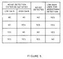
- FIGS. 5-9refer to the four conditions which can result when the noise detection criterion is simultaneously applied to the low gain and the high gain channels. Noise is detected when the noise detection criterion is satisfied on the high gain channel. When noise is detected, the low gain signal can still be used for arrhythmia detection except when the noise detection criterion is also satisfied on the low gain channel.
- FIG. 5depicts the four possible conditions of the noise detection algorithm. They are (i) the noise detection criterion is not satisfied on either the low gain channel or the high gain channel and therefore noise is not detected and the low gain channel can be used for arrhythmia detection; (ii) the noise detection criterion is not satisfied on the low gain channel but it is satisfied on the high gain channel and therefore noise is detected but the low gain channel can still be used for arrhythmia detection; (iii) the noise detection criterion is satisfied on the low gain channel but not on the high gain channel and therefore noise is not detected and the low gain channel can be used for arrhythmia detection; and (iv) the noise detection criterion is satisfied on both the low gain channel and the high gain channel and therefore noise is detected and the low gain channel cannot be used for arrhythmia detection.
- FIG. 6depicts the operation of the sensing circuitry of FIG. 3 when noise is not detected.
- the detected analog signal 90is shown to be sinus rhythm.
- the noise detection criterionis not satisfied on either the low gain channel 92 or the high gain channel 94.
- the low gain channelis therefore used for arrhythmia detection which establishes that an arrhythmia does not exit.
- FIG. 7depicts the operation of the sensing circuitry of FIG. 3 when noise is detected.
- Low amplitude noiseis shown to be present on the detected analog signal 100.
- NDI100 milliseconds and hence noise is detected.
- this signalis still used for arrhythmia detection which establishes that an arrhythmia does not exist.
- FIG. 8depicts the operation of the sensing circuitry of FIG. 3 when noise is not detected.
- FIG. 9depicts the detection of noise using the sensing circuitry of FIG. 3.
- noiseis present in the signal.
- the tachycardia detection criterionis therefore satisfied on the low gain channel.
- the noise detection criterionis also satisfied on both the low gain channel and the high gain channel. The noise present in the signal has therefore been correctly detected and the unnecessary delivery of antitachyarrhythmia therapy to the patient has been avoided.
- the noise detection criterionmay be applied to the high gain channel only.
- the low gain channelis used for arrhythmia detection except for when noise is detected, that is, the noise detection criterion is satisfied on the high gain channel.
- the noise detection intervalscould include frequency histograms or statistical measures, such as means, medians or variance which may be implemented with suitable programming of the microprocessor.
Landscapes
- Health & Medical Sciences (AREA)
- Life Sciences & Earth Sciences (AREA)
- Cardiology (AREA)
- Animal Behavior & Ethology (AREA)
- Biomedical Technology (AREA)
- Nuclear Medicine, Radiotherapy & Molecular Imaging (AREA)
- Radiology & Medical Imaging (AREA)
- Engineering & Computer Science (AREA)
- Heart & Thoracic Surgery (AREA)
- General Health & Medical Sciences (AREA)
- Public Health (AREA)
- Veterinary Medicine (AREA)
- Biophysics (AREA)
- Physiology (AREA)
- Electrotherapy Devices (AREA)
- Measurement And Recording Of Electrical Phenomena And Electrical Characteristics Of The Living Body (AREA)
Description
- This invention relates to implantable medical devices which monitor the cardiac state of a patient by sensing the patient's intrinsic rhythm for the presence of arrhythmias and which deliver therapy in the form of electrical energy to cardiac tissue in an attempt to revert detected arrhythmias and restore a normal sinus rhythm to the patient.
- As used herein, the term arrhythmia refers to any abnormal rhythm of the heart which may be amenable to treatment by electrical discharges and specifically includes tachyarrhythmias, fibrillation, tachycardias, supraventricular tachycardia (SVT), ventricular tachycardia (VT), ventricular flutter and ventricular fibrillation (VF), and bradycardia.
- The term therapy as used herein includes the processes used between the detection and reversion of an arrhythmia and includes the actions of antitachycardia or bradycardia pacing and cardioversion. The term cardioversion refers to the discharge of electrical energy onto the cardiac tissue in an attempt to terminate or revert a tachycardia and may range from a high (40 Joules or more) to a low (less than 1 Joule) energy discharge. The discharge may be monophasic or biphasic but is not restricted to these waveforms. Cardioversion shocks may or may not be synchronized to the rhythm of the heart. Defibrillation is a particular example of cardioversion.
- This invention applies equally to devices which deliver energy synchronised to an R-wave and to those that do not, and it applies to devices which use lower energy pulses (up to 1 Joule) as well as to devices which deliver cardioversion shocks alone or in combination with antitachycardia and bradycardia pacing pulses.
- Noise protection circuits have been incorporated into demand pacemakers in order to prevent noise signals from being detected as natural heart beats. When such false detection occurs, the artificial stimulation is suppressed thus leading to a potentially dangerous situation for the patient. These noise protection circuits include filters to attenuate noise signals of particular frequencies and refractory periods during which time detected signals are ignored as described in U.S. Patent No. 4,173,230 to Digby entitled "Noise Elimination and Refractory Period Control in Demand Pacers".
- U.S. Patent No. 4,649,931 to Beck entitled "Sampled Data Sense Amplifier" describes a sense amplifier for a cardiac pacemaker which generates a detect signal in response to a depolarization of cardiac tissue. In operation, this sensing system searches for a sampling frequency which permits the detection of the physiological signal in the presence of continuous wave noise. This is a time-consuming procedure which is appropriate only when the interference present is periodic. Noise protection is also important in antitachyarrhythmia devices where the false detection of noise signals may lead to the delivery of unnecessary therapy to the patient. Known antitachyarrhythmia devices use a single channel for sensing and require a predetermined number of intervals to lie within a specified window for a tachyarrhythmia to be detected. The intermittent sensing of low level noise can, however, lead to the false detection of tachycardia and the subsequent delivery of unnecessary and possibly fatal therapy to the patient.
- The switching of gains can be used in single channel devices to alter the sensitivity required at the sensing electrode for a sense to be registered. The adaptation of this technique for noise detection would result in undesirable time delays in the detection procedure and in the delivery of any subsequent therapy.
- There is a need, therefore, for a device which is capable of reliably differentiating between an arrhythmia and noise and having a minimal time delay for the detection procedure.
- EP-A-253 505 discloses an antiarrhythmia device comprising an apparatus for differentiating between arrhythmia and noise in a signal from a patient's heart. The signal from the heart is led through two channels. The gain of one channel is set by a computer but, when set to high gain, it is not used for noise detection.
- It is an object of the invention to increase patient safety by reliably detecting noise in an implantable arrhythmia control device.
- It is a further object of the invention to reliably differentiate between an arrhythmia and noise by means of a detection procedure having a minimal time delay.
- According to the invention, there is provided an antiarrhythmia device comprising an apparatus for differentiating between arrhythmia and noise in a signal from a patient's heart charactrised by: a high gain channel detecting means for receiving the above signal for noise detection; a low gain channel detecting means for detecting the presence of an arrhythmia in the above signal when no noise is detected by said high gain channel detecting means; arrhythmia therapy means responsive to said low gain channel detecting means for delivering arrhythmia therapy; and means for applying a noise detection criterion to said high gain channel detecting means.
- There is further provided a method of operating an antiarrhythmia device to differentiate between arrhythmia and noise, characterised by: applying a noise detection criterion to a high gain channel detecting means; receiving a signal from a patient's heart in said high gain channel detecting means and detecting the presence of noise in the signal; detecting, using a low gain channel detecting means as a noise free channel, irrespective of time varying amplitudes, the presence of an arrhythmia in said signal when no noise is detected by said high gain channel detecting means; delivering arrhythmia therapy in response to detection of an arrhythmia by said low gain channel detecting means.
- Further objects, features, and advantages of the invention will become apparent upon consideration of the following detailed description in conjunction with the drawings, and given by way of example only, in which :-
- FIG. 1 is a block diagram of an arrhythmia control system;
- FIG. 2 is a block diagram of the pacemaker of FIG. 1;
- FIG. 3 is a block diagram of the sensing circuitry of FIG. 2;
- FIG. 4 is a block diagram of the microprocessor of FIG. 1;
- FIG. 5 is a table illustrating the detection of a tachycardia using the sensing circuitry of FIG. 3; and
- FIGS. 6-9 illustrate the detection of noise using the sensing circuitry of FIG. 3.
- Referring to FIG. 1, there is depicted a block diagram of an arrhythmia control system (ACS) 10 which comprises: a
cardiac lead 12 connected to the patient'sheart 11; apacemaker 16 for the detection of analog signals representing cardiac electrical activity and for the delivery of pacing pulses to the heart; amicroprocessor 19 which, in response to various inputs received from thepacemaker 16 as well as from thedefibrillator 15, performs various operations so as to generate different control and data outputs to both thepacemaker 16 and thedefibrillator 15 which produces a high voltage to charge its capacitors and then discharges them in response to control signals from themicroprocessor 19; and adefibrillator electrode lead 13 for transferring the energy of adefibrillator shock 14 from theACS 10 to the surface of the heart. ACS 10 is preferably an implanted device. - Referring to FIG. 2, there is depicted a block diagram of the
pacemaker 16 of FIG. 1. As seen therein,pacemaker 16 comprises circuitry forpacing 24, sensing 25, andtelemetry 31. In addition, there is acontrol block 32. - In operation, the
sensing circuitry 25 detectsanalog signals 23 from theheart 20 and converts the detected signals to digital signals. Furthermore, thesensing circuitry 25 receivesinput sense controls control block 32 which determine the sensitivities applied to the detection circuits. A change in these sensitivities will affect the voltage deviation required at the sensing electrode for senses to be registered. There are various types of logic arrangements which can be used to change the sensitivity corresponding to the detection of cardiac activity. - The
pacing circuitry 24 also receives inputs from thecontrol block 32 including a pace control and a pacing energy control. The pace control determines the type of pacing to occur while the magnitude of the pulse energy is determined by the pacing energy control. The operation of the logic which changes the pulse energy is described in more detail in the co-pending European Patent Application No. 89.300232.9 filed 11th January 1989 entitled "Apparatus and Method for Controlling Pulse Energy in Antitachyarrhythmia and Bradycardia Pacing Device". Thepacing circuitry 24 generates thepacing pulse 22 which is delivered to the patient'sheart 20 by means of thecardiac lead 21. - The
telemetry circuit 31 provides a bi-directional link between thecontrol block 32 and an external device such as a programmer. It allows data such as the operating parameters to be read from or altered in the ACS implant. - Referring to FIG. 3, there is shown a block diagram of the
sensing circuitry 25 of FIG. 2. As seen therein, the sensing circuitry comprises twoamplifiers comparators analog signal 23 is input to both thelow gain amplifier 41 and thehigh gain amplifier 42 where, in a preferred embodiment, there is a 3-6 dB difference in the gain ofamplifier 41 to amplifier 42. The output of the low gain amplifier is compared with the lowgain control signal 28 bycomparator 43. The level of this low gain control signal is selected so that cardiac activity is reliably sensed. Similarly, the output of the high gain amplifier is compared with the highgain control signal 30 bycomparator 44 where the level of this high gain control signal 48 is set so that noise activity is reliably sensed. - Referring to FIG. 4, there is shown a block diagram of the
microprocessor 19 of FIG. 1. It comprises two 16-bit timers CPU 67, vectoredinterrupt block 68,ROM 62,RAM 63,external memory 64,ports 61 and an internal communication bus 60. - The
microprocessor 19 receives various status and/or control inputs frompacemaker 16 anddefibrillator 15 such as thelow gain sense 27 and thehigh gain sense 29, and performs operations such as arrhythmia detection and noise detection. Tachycardia detection may be performed using any known tachycardia detection algorithm. In a preferred embodiment, an x out of y tachycardia detection criterion is used. This requires at least x intervals out of the previous y intervals to be less than the tachycardia detection interval (TDI). Similarly, noise detection may be performed using any known noise detection algorithm. In a preferred embodiment, an n out of z noise detection criterion is used. This requires at least n intervals in the previous z intervals to be less than the noise detection interval (NDI). - The control outputs generated by the
microprocessor 19 include thepace control 77 which determines the type of pacing to take place, thepacing energy control 74 which determines the magnitude of the pulse energy, theshock control 71 which signals that a shock is to be delivered to the patient, thedump control 70 which indicates that a shock is to be dumped at an internal load within the defibrillator, thecharge control 72 which determines the voltage level of the shock to be delivered, and the sensitivity controls, low gain control 75 and high gain control 76, which determine the sensitivity settings of the sensing circuits. - FIGS. 5-9 refer to the four conditions which can result when the noise detection criterion is simultaneously applied to the low gain and the high gain channels. Noise is detected when the noise detection criterion is satisfied on the high gain channel. When noise is detected, the low gain signal can still be used for arrhythmia detection except when the noise detection criterion is also satisfied on the low gain channel. In a preferred embodiment, the noise detection criterion is satisfied on the low gain channel when at least n intervals in the previous z intervals are less than the NDI where n = 2, z = 10 and NDI = 100 milliseconds and on the high gain channel when at least n' intervals in the previous z' intervals are less than the NDI where n' = 9, z' = 10 and NDI = 100 milliseconds.
- FIG. 5 depicts the four possible conditions of the noise detection algorithm. They are (i) the noise detection criterion is not satisfied on either the low gain channel or the high gain channel and therefore noise is not detected and the low gain channel can be used for arrhythmia detection; (ii) the noise detection criterion is not satisfied on the low gain channel but it is satisfied on the high gain channel and therefore noise is detected but the low gain channel can still be used for arrhythmia detection; (iii) the noise detection criterion is satisfied on the low gain channel but not on the high gain channel and therefore noise is not detected and the low gain channel can be used for arrhythmia detection; and (iv) the noise detection criterion is satisfied on both the low gain channel and the high gain channel and therefore noise is detected and the low gain channel cannot be used for arrhythmia detection.
- FIG. 6 depicts the operation of the sensing circuitry of FIG. 3 when noise is not detected. The detected
analog signal 90 is shown to be sinus rhythm. The noise detection criterion is not satisfied on either thelow gain channel 92 or thehigh gain channel 94. The low gain channel is therefore used for arrhythmia detection which establishes that an arrhythmia does not exit. - FIG. 7 depicts the operation of the sensing circuitry of FIG. 3 when noise is detected. Low amplitude noise is shown to be present on the detected
analog signal 100. The noise detection criterion is not satisfied on thelow gain channel 102 but at least n' = 9 out of the previous z' = 10 intervals on thehigh gain channel 104 are less than NDI = 100 milliseconds and hence noise is detected. However, because the amplitude of the noise is such that it has not affected the low gain channel, this signal is still used for arrhythmia detection which establishes that an arrhythmia does not exist. - FIG. 8 depicts the operation of the sensing circuitry of FIG. 3 when noise is not detected. The detected
analog signal 110 is shown to be sinus rhythm. Double sensing of thesignal 110 is seen to occur, resulting in at least n = 2 out of the previous z = 10 intervals on thelow gain channel 112 being less than NDI = 100 milliseconds thus satisfying the noise detection criterion on the low gain channel. However, at least n' = 9 out of the previous z' = 10 intervals are not less than NDI' = 100 milliseconds on thehigh gain channel 114. Therefore, noise is not detected and the low gain channel is used for arrhythmia detection which establishes that an arrhythmia does not exist. - FIG. 9 depicts the detection of noise using the sensing circuitry of FIG. 3. As shown at 120, noise is present in the signal. The low gain channel intermittently senses the noise activity and as a consequence at least x out of y sensed intervals are less than the TDI where x = 8, y = 10, and TDI = 400 milliseconds in a preferred embodiment. The tachycardia detection criterion is therefore satisfied on the low gain channel. However, the noise detection criterion is also satisfied on both the low gain channel and the high gain channel. The noise present in the signal has therefore been correctly detected and the unnecessary delivery of antitachyarrhythmia therapy to the patient has been avoided.
- Although the invention has been described with reference to a particular embodiment, it is to be understood that this embodiment is merely illustrative of the application of the principles of the invention. For example, the noise detection criterion may be applied to the high gain channel only. In this case, the low gain channel is used for arrhythmia detection except for when noise is detected, that is, the noise detection criterion is satisfied on the high gain channel. Furthermore, the noise detection intervals could include frequency histograms or statistical measures, such as means, medians or variance which may be implemented with suitable programming of the microprocessor.
Claims (11)
Applications Claiming Priority (3)
| Application Number | Priority Date | Filing Date | Title |
|---|---|---|---|
| AU734788 | 1988-03-21 | ||
| AUPI734788 | 1988-03-21 | ||
| AU7347/88 | 1988-03-21 |
Publications (3)
| Publication Number | Publication Date |
|---|---|
| EP0334618A1 EP0334618A1 (en) | 1989-09-27 |
| EP0334618B1true EP0334618B1 (en) | 1995-01-04 |
| EP0334618B2 EP0334618B2 (en) | 2001-12-05 |
Family
ID=3772939
Family Applications (1)
| Application Number | Title | Priority Date | Filing Date |
|---|---|---|---|
| EP89302815AExpired - LifetimeEP0334618B2 (en) | 1988-03-21 | 1989-03-21 | Differentiating between arrhythmia and noise in an arrhythmia control system |
Country Status (4)
| Country | Link |
|---|---|
| US (1) | US4960123A (en) |
| EP (1) | EP0334618B2 (en) |
| CA (1) | CA1323070C (en) |
| DE (1) | DE68920350T3 (en) |
Cited By (1)
| Publication number | Priority date | Publication date | Assignee | Title |
|---|---|---|---|---|
| US7756570B1 (en) | 2006-05-01 | 2010-07-13 | Pacesetter, Inc. | Methods and arrangements for reducing oversensing and/or providing diagnostic information in implantable medical devices |
Families Citing this family (30)
| Publication number | Priority date | Publication date | Assignee | Title |
|---|---|---|---|---|
| US5178140A (en)* | 1991-09-05 | 1993-01-12 | Telectronics Pacing Systems, Inc. | Implantable medical devices employing capacitive control of high voltage switches |
| US5251625A (en)* | 1991-10-22 | 1993-10-12 | Telectronics Pacing Systems, Inc. | Apparatus and method for controlling tachyarrhythmia confirmation in response to patient history |
| US5327900A (en)* | 1991-11-01 | 1994-07-12 | Telectronics Pacing Systems, Inc. | Apparatus and method for discriminating between heart rhythms with similar atrial and ventricular rates |
| DE59209140D1 (en)* | 1992-07-31 | 1998-02-19 | Pacesetter Ab | Device for detecting cardiac events |
| US5685315A (en)* | 1992-12-01 | 1997-11-11 | Pacesetter, Inc. | Cardiac arrhythmia detection system for an implantable stimulation device |
| AU5205493A (en)* | 1992-12-01 | 1994-06-16 | Siemens Aktiengesellschaft | Cardiac event detection in implantable medical devices |
| FR2712500B1 (en)* | 1993-11-17 | 1996-02-09 | Ela Medical Sa | Method for automatically controlling the heart rate detection threshold in an implantable device. |
| US5507778A (en)* | 1994-02-22 | 1996-04-16 | Zmd Corporation | Semiautomatic defibrillator with synchronized shock delivery |
| US5391187A (en)* | 1994-02-22 | 1995-02-21 | Zmd Corporation | Semiautomatic defibrillator with heart rate alarm driven by shock advisory algorithm |
| US5759196A (en)* | 1995-09-29 | 1998-06-02 | Medtronic, Inc. | Modification of pacemaker tachy response based on FFRW sensing |
| US5558098A (en)* | 1995-11-02 | 1996-09-24 | Ventritex, Inc. | Method and apparatus for detecting lead sensing artifacts in cardiac electrograms |
| US5782876A (en)* | 1996-04-15 | 1998-07-21 | Medtronic, Inc. | Method and apparatus using windows and an index value for identifying cardic arrhythmias |
| US5702425A (en)* | 1996-08-13 | 1997-12-30 | Pacesetter, Inc. | Apparatus and method of noise classification in an implantable cardiac device |
| US5897575A (en)* | 1997-10-24 | 1999-04-27 | Pacesetter, Inc. | Arrhythmia classification system with reliability indication that allows for low quality input signals in pacemakers |
| US5910156A (en)* | 1997-11-07 | 1999-06-08 | Medtronic Inc. | Non-physiologic sense detection for implantable medical devices |
| US5978710A (en) | 1998-01-23 | 1999-11-02 | Sulzer Intermedics Inc. | Implantable cardiac stimulator with safe noise mode |
| US6016446A (en)* | 1998-02-27 | 2000-01-18 | Cardiac Pacemakers, Inc. | Cardiac rhythm management system including nonlinear, non-blanking sense amplifier |
| US6223072B1 (en)* | 1999-06-08 | 2001-04-24 | Impulse Dynamics N.V. | Apparatus and method for collecting data useful for determining the parameters of an alert window for timing delivery of ETC signals to a heart under varying cardiac conditions |
| FR2803211B1 (en)* | 1999-12-29 | 2002-02-22 | Ela Medical Sa | ACTIVE IMPLANTABLE MEDICAL DEVICE, IN PARTICULAR A CARDIAC STIMULATOR, DEFIBRILLATOR AND / OR CARDIOVECTOR, INCLUDING MEANS FOR ELIMINATING EVENT DETECTION ARTIFACTS |
| US7998720B2 (en)* | 2000-02-21 | 2011-08-16 | Puratos N.V. | Enzyme with xylanase activity |
| US6493584B1 (en)* | 2000-09-08 | 2002-12-10 | Pacesetter, Inc. | Implantable cardiac stimulation device and method which discriminates between noise and cardiac activity |
| US7386344B2 (en)* | 2004-08-11 | 2008-06-10 | Cardiac Pacemakers, Inc. | Pacer with combined defibrillator tailored for bradycardia patients |
| US6751502B2 (en) | 2001-03-14 | 2004-06-15 | Cardiac Pacemakers, Inc. | Cardiac rhythm management system with defibrillation threshold prediction |
| US7215993B2 (en)* | 2002-08-06 | 2007-05-08 | Cardiac Pacemakers, Inc. | Cardiac rhythm management systems and methods for detecting or validating cardiac beats in the presence of noise |
| US6917830B2 (en)* | 2001-10-29 | 2005-07-12 | Cardiac Pacemakers, Inc. | Method and system for noise measurement in an implantable cardiac device |
| US6892092B2 (en)* | 2001-10-29 | 2005-05-10 | Cardiac Pacemakers, Inc. | Cardiac rhythm management system with noise detector utilizing a hysteresis providing threshold |
| US7650182B2 (en)* | 2005-07-08 | 2010-01-19 | Cardiac Pacemakers, Inc. | Dual sensing for brady-tachy pacemaker/ICD |
| US8382177B2 (en)* | 2009-06-11 | 2013-02-26 | Re2, Inc. | Quick-change finger for robotic gripper |
| US8694097B2 (en) | 2010-06-30 | 2014-04-08 | Medtronic, Inc. | Multi-channel sensing methods in implantable cardiovertor defibrillators |
| US8744556B2 (en) | 2011-02-04 | 2014-06-03 | Cardiac Pacemakers, Inc. | Noise detection in implantable medical devices |
Family Cites Families (14)
| Publication number | Priority date | Publication date | Assignee | Title |
|---|---|---|---|---|
| US3677260A (en)* | 1970-09-04 | 1972-07-18 | Statham Instrument Inc | Arrhythmia detector |
| US3927663A (en)* | 1974-05-02 | 1975-12-23 | Phsiological Electronics Corp | Method and apparatus for detecting cardiac arrhythmias |
| US3985142A (en)* | 1975-01-14 | 1976-10-12 | Telectronics Pty. Limited | Demand heart pacer with improved interference discrimination |
| US4135159A (en)* | 1976-03-08 | 1979-01-16 | The United States Of America As Represented By The Secretary Of The Army | Apparatus for suppressing a strong electrical signal |
| US4173230A (en)* | 1977-08-19 | 1979-11-06 | Biotronik Mess- Und Therapiegerate Gmbh & Co. | Noise elimination and refractory period control in demand pacers |
| DE2805681C2 (en)* | 1978-02-10 | 1979-11-22 | Siemens Ag, 1000 Berlin Und 8000 Muenchen | Circuit arrangement for suppressing interference signals in a useful signal |
| FR2440199A1 (en)* | 1978-11-06 | 1980-05-30 | Medtronic Inc | ON-DEMAND CARDIAC STIMULATOR |
| US4649931A (en)* | 1981-03-02 | 1987-03-17 | Medtronic, Inc. | Sampled data sense amplifier |
| US4379459A (en)* | 1981-04-09 | 1983-04-12 | Medtronic, Inc. | Cardiac pacemaker sense amplifier |
| DE3232478C1 (en)* | 1982-09-01 | 1984-03-01 | Werner Prof. Dr.-Ing. 6301 Wettenberg Irnich | Synchronizable pacemaker |
| US4638808A (en)* | 1984-08-16 | 1987-01-27 | Rca Corporation | Circuit for separating one type signal component from another |
| JPS62175025A (en)* | 1986-01-25 | 1987-07-31 | Fujitsu Ten Ltd | Noise eliminator |
| US4766902A (en)* | 1986-06-04 | 1988-08-30 | Telectronics N.V. | Automatic sensitivity control for cardiac pacer |
| US4830006B1 (en)* | 1986-06-17 | 1997-10-28 | Intermedics Inc | Implantable cardiac stimulator for detection and treatment of ventricular arrhythmias |
- 1989
- 1989-03-16USUS07/324,487patent/US4960123A/ennot_activeExpired - Lifetime
- 1989-03-20CACA000594252Apatent/CA1323070C/ennot_activeExpired - Fee Related
- 1989-03-21EPEP89302815Apatent/EP0334618B2/ennot_activeExpired - Lifetime
- 1989-03-21DEDE68920350Tpatent/DE68920350T3/ennot_activeExpired - Fee Related
Cited By (1)
| Publication number | Priority date | Publication date | Assignee | Title |
|---|---|---|---|---|
| US7756570B1 (en) | 2006-05-01 | 2010-07-13 | Pacesetter, Inc. | Methods and arrangements for reducing oversensing and/or providing diagnostic information in implantable medical devices |
Also Published As
| Publication number | Publication date |
|---|---|
| CA1323070C (en) | 1993-10-12 |
| DE68920350T2 (en) | 1995-07-06 |
| DE68920350D1 (en) | 1995-02-16 |
| EP0334618B2 (en) | 2001-12-05 |
| EP0334618A1 (en) | 1989-09-27 |
| DE68920350T3 (en) | 2002-07-25 |
| US4960123A (en) | 1990-10-02 |
Similar Documents
| Publication | Publication Date | Title |
|---|---|---|
| EP0334618B1 (en) | Differentiating between arrhythmia and noise in an arrhythmia control system | |
| US4940054A (en) | Apparatus and method for controlling multiple sensitivities in arrhythmia control system including post therapy packing delay | |
| US5447518A (en) | Method and apparatus for phase related cardiac defibrillation | |
| AU757287B2 (en) | Cardioverter and method for cardioverting an atrial tachyarrhythmia while maintaining atrial pacing | |
| EP0518599B1 (en) | Implantable pacemaker/cardioverter/defibrillator device for incorporating multiple bradycardia support pacing rates | |
| US5184615A (en) | Apparatus and method for detecting abnormal cardiac rhythms using evoked potential measurements in an arrhythmia control system | |
| US4869252A (en) | Apparatus and method for controlling pulse energy in antitachyarrhythmia and bradycardia pacing device | |
| US7376464B2 (en) | Method and system for automatic anti-tachycardia pacing | |
| EP0350160B1 (en) | Implantable cardiac stimulator with automatic gain control and bandpass filtering in feedback loop | |
| EP1109597B1 (en) | Cardioverter for cardioverting an atrial tachyarrhythmia in the presence of atrial pacing | |
| US6249701B1 (en) | Implantable device with automatic sensing adjustment | |
| US20020147468A1 (en) | Apparatus and method for R-wave detection with dual dynamic sensitivities | |
| US7991469B2 (en) | Pacing therapy for extending atrial refractory period | |
| US6643547B2 (en) | Method and device for sensing atrial depolarizations during ventricular tachycardia | |
| US6208899B1 (en) | Implantable cardioversion device with automatic filter control | |
| EP0340045B1 (en) | Apparatus for reversion of tachyarrhythmia including post therapy pacing delay | |
| US7313438B2 (en) | Selective chamber ATP pacing | |
| EP1758646A1 (en) | Atp pacing with entrainment monitoring |
Legal Events
| Date | Code | Title | Description |
|---|---|---|---|
| PUAI | Public reference made under article 153(3) epc to a published international application that has entered the european phase | Free format text:ORIGINAL CODE: 0009012 | |
| AK | Designated contracting states | Kind code of ref document:A1 Designated state(s):DE FR GB IT NL | |
| 17P | Request for examination filed | Effective date:19900321 | |
| 17Q | First examination report despatched | Effective date:19920710 | |
| GRAA | (expected) grant | Free format text:ORIGINAL CODE: 0009210 | |
| AK | Designated contracting states | Kind code of ref document:B1 Designated state(s):DE FR GB IT NL | |
| ITF | It: translation for a ep patent filed | ||
| REF | Corresponds to: | Ref document number:68920350 Country of ref document:DE Date of ref document:19950216 | |
| ET | Fr: translation filed | ||
| PLBI | Opposition filed | Free format text:ORIGINAL CODE: 0009260 | |
| 26 | Opposition filed | Opponent name:BIOTRONIK MESS- UND THERAPIEGERAETE GMBH & CO INGE Effective date:19951004 | |
| NLR1 | Nl: opposition has been filed with the epo | Opponent name:BIOTRONIK MESS- UND THERAPIEGERAETE GMBH & CO INGE | |
| PLBF | Reply of patent proprietor to notice(s) of opposition | Free format text:ORIGINAL CODE: EPIDOS OBSO | |
| PGFP | Annual fee paid to national office [announced via postgrant information from national office to epo] | Ref country code:GB Payment date:19970312 Year of fee payment:9 | |
| PG25 | Lapsed in a contracting state [announced via postgrant information from national office to epo] | Ref country code:GB Free format text:LAPSE BECAUSE OF NON-PAYMENT OF DUE FEES Effective date:19980321 | |
| PGFP | Annual fee paid to national office [announced via postgrant information from national office to epo] | Ref country code:NL Payment date:19980326 Year of fee payment:10 | |
| GBPC | Gb: european patent ceased through non-payment of renewal fee | Effective date:19980321 | |
| PG25 | Lapsed in a contracting state [announced via postgrant information from national office to epo] | Ref country code:NL Free format text:LAPSE BECAUSE OF NON-PAYMENT OF DUE FEES Effective date:19991001 | |
| PLBQ | Unpublished change to opponent data | Free format text:ORIGINAL CODE: EPIDOS OPPO | |
| PLAB | Opposition data, opponent's data or that of the opponent's representative modified | Free format text:ORIGINAL CODE: 0009299OPPO | |
| NLV4 | Nl: lapsed or anulled due to non-payment of the annual fee | Effective date:19991001 | |
| R26 | Opposition filed (corrected) | Opponent name:BIOTRONIK MESS- UND THERAPIEGERAETE GMBH & CO INGE Effective date:19951004 | |
| PLAW | Interlocutory decision in opposition | Free format text:ORIGINAL CODE: EPIDOS IDOP | |
| APAC | Appeal dossier modified | Free format text:ORIGINAL CODE: EPIDOS NOAPO | |
| APAE | Appeal reference modified | Free format text:ORIGINAL CODE: EPIDOS REFNO | |
| PLAW | Interlocutory decision in opposition | Free format text:ORIGINAL CODE: EPIDOS IDOP | |
| PUAH | Patent maintained in amended form | Free format text:ORIGINAL CODE: 0009272 | |
| STAA | Information on the status of an ep patent application or granted ep patent | Free format text:STATUS: PATENT MAINTAINED AS AMENDED | |
| APAC | Appeal dossier modified | Free format text:ORIGINAL CODE: EPIDOS NOAPO | |
| 27A | Patent maintained in amended form | Effective date:20011205 | |
| AK | Designated contracting states | Kind code of ref document:B2 Designated state(s):DE FR GB IT NL | |
| PGFP | Annual fee paid to national office [announced via postgrant information from national office to epo] | Ref country code:FR Payment date:20040318 Year of fee payment:16 | |
| PG25 | Lapsed in a contracting state [announced via postgrant information from national office to epo] | Ref country code:IT Free format text:LAPSE BECAUSE OF NON-PAYMENT OF DUE FEES;WARNING: LAPSES OF ITALIAN PATENTS WITH EFFECTIVE DATE BEFORE 2007 MAY HAVE OCCURRED AT ANY TIME BEFORE 2007. THE CORRECT EFFECTIVE DATE MAY BE DIFFERENT FROM THE ONE RECORDED. Effective date:20050321 | |
| PGFP | Annual fee paid to national office [announced via postgrant information from national office to epo] | Ref country code:DE Payment date:20050502 Year of fee payment:17 | |
| APAH | Appeal reference modified | Free format text:ORIGINAL CODE: EPIDOSCREFNO | |
| PG25 | Lapsed in a contracting state [announced via postgrant information from national office to epo] | Ref country code:FR Free format text:LAPSE BECAUSE OF NON-PAYMENT OF DUE FEES Effective date:20051130 | |
| REG | Reference to a national code | Ref country code:FR Ref legal event code:ST Effective date:20051130 | |
| PG25 | Lapsed in a contracting state [announced via postgrant information from national office to epo] | Ref country code:DE Free format text:LAPSE BECAUSE OF NON-PAYMENT OF DUE FEES Effective date:20061003 |