EP0333990B1 - Surgical instrument set - Google Patents
Surgical instrument setDownload PDFInfo
- Publication number
- EP0333990B1 EP0333990B1EP89101147AEP89101147AEP0333990B1EP 0333990 B1EP0333990 B1EP 0333990B1EP 89101147 AEP89101147 AEP 89101147AEP 89101147 AEP89101147 AEP 89101147AEP 0333990 B1EP0333990 B1EP 0333990B1
- Authority
- EP
- European Patent Office
- Prior art keywords
- surgical instrument
- instrument set
- accordance
- expansion
- jaws
- Prior art date
- Legal status (The legal status is an assumption and is not a legal conclusion. Google has not performed a legal analysis and makes no representation as to the accuracy of the status listed.)
- Expired - Lifetime
Links
Images


Classifications
- A—HUMAN NECESSITIES
- A61—MEDICAL OR VETERINARY SCIENCE; HYGIENE
- A61B—DIAGNOSIS; SURGERY; IDENTIFICATION
- A61B17/00—Surgical instruments, devices or methods
- A61B17/02—Surgical instruments, devices or methods for holding wounds open, e.g. retractors; Tractors
- A61B17/025—Joint distractors
- A—HUMAN NECESSITIES
- A61—MEDICAL OR VETERINARY SCIENCE; HYGIENE
- A61B—DIAGNOSIS; SURGERY; IDENTIFICATION
- A61B17/00—Surgical instruments, devices or methods
- A61B17/28—Surgical forceps
- A61B17/2804—Surgical forceps with two or more pivotal connections
- A—HUMAN NECESSITIES
- A61—MEDICAL OR VETERINARY SCIENCE; HYGIENE
- A61F—FILTERS IMPLANTABLE INTO BLOOD VESSELS; PROSTHESES; DEVICES PROVIDING PATENCY TO, OR PREVENTING COLLAPSING OF, TUBULAR STRUCTURES OF THE BODY, e.g. STENTS; ORTHOPAEDIC, NURSING OR CONTRACEPTIVE DEVICES; FOMENTATION; TREATMENT OR PROTECTION OF EYES OR EARS; BANDAGES, DRESSINGS OR ABSORBENT PADS; FIRST-AID KITS
- A61F2/00—Filters implantable into blood vessels; Prostheses, i.e. artificial substitutes or replacements for parts of the body; Appliances for connecting them with the body; Devices providing patency to, or preventing collapsing of, tubular structures of the body, e.g. stents
- A61F2/02—Prostheses implantable into the body
- A61F2/30—Joints
- A61F2/44—Joints for the spine, e.g. vertebrae, spinal discs
- A61F2/442—Intervertebral or spinal discs, e.g. resilient
- A61F2/4425—Intervertebral or spinal discs, e.g. resilient made of articulated components
- A—HUMAN NECESSITIES
- A61—MEDICAL OR VETERINARY SCIENCE; HYGIENE
- A61F—FILTERS IMPLANTABLE INTO BLOOD VESSELS; PROSTHESES; DEVICES PROVIDING PATENCY TO, OR PREVENTING COLLAPSING OF, TUBULAR STRUCTURES OF THE BODY, e.g. STENTS; ORTHOPAEDIC, NURSING OR CONTRACEPTIVE DEVICES; FOMENTATION; TREATMENT OR PROTECTION OF EYES OR EARS; BANDAGES, DRESSINGS OR ABSORBENT PADS; FIRST-AID KITS
- A61F2/00—Filters implantable into blood vessels; Prostheses, i.e. artificial substitutes or replacements for parts of the body; Appliances for connecting them with the body; Devices providing patency to, or preventing collapsing of, tubular structures of the body, e.g. stents
- A61F2/02—Prostheses implantable into the body
- A61F2/30—Joints
- A61F2/46—Special tools for implanting artificial joints
- A61F2/4603—Special tools for implanting artificial joints for insertion or extraction of endoprosthetic joints or of accessories thereof
- A61F2/4611—Special tools for implanting artificial joints for insertion or extraction of endoprosthetic joints or of accessories thereof of spinal prostheses
- A—HUMAN NECESSITIES
- A61—MEDICAL OR VETERINARY SCIENCE; HYGIENE
- A61B—DIAGNOSIS; SURGERY; IDENTIFICATION
- A61B17/00—Surgical instruments, devices or methods
- A61B17/02—Surgical instruments, devices or methods for holding wounds open, e.g. retractors; Tractors
- A61B17/025—Joint distractors
- A61B2017/0256—Joint distractors for the spine
- A—HUMAN NECESSITIES
- A61—MEDICAL OR VETERINARY SCIENCE; HYGIENE
- A61F—FILTERS IMPLANTABLE INTO BLOOD VESSELS; PROSTHESES; DEVICES PROVIDING PATENCY TO, OR PREVENTING COLLAPSING OF, TUBULAR STRUCTURES OF THE BODY, e.g. STENTS; ORTHOPAEDIC, NURSING OR CONTRACEPTIVE DEVICES; FOMENTATION; TREATMENT OR PROTECTION OF EYES OR EARS; BANDAGES, DRESSINGS OR ABSORBENT PADS; FIRST-AID KITS
- A61F2/00—Filters implantable into blood vessels; Prostheses, i.e. artificial substitutes or replacements for parts of the body; Appliances for connecting them with the body; Devices providing patency to, or preventing collapsing of, tubular structures of the body, e.g. stents
- A61F2/02—Prostheses implantable into the body
- A61F2/30—Joints
- A61F2002/30001—Additional features of subject-matter classified in A61F2/28, A61F2/30 and subgroups thereof
- A61F2002/30621—Features concerning the anatomical functioning or articulation of the prosthetic joint
- A61F2002/30639—Features concerning the anatomical functioning or articulation of the prosthetic joint having rolling elements between both articulating surfaces
- A61F2002/30642—Features concerning the anatomical functioning or articulation of the prosthetic joint having rolling elements between both articulating surfaces having a single rolling (or sliding) ball articulating between two cups
- A—HUMAN NECESSITIES
- A61—MEDICAL OR VETERINARY SCIENCE; HYGIENE
- A61F—FILTERS IMPLANTABLE INTO BLOOD VESSELS; PROSTHESES; DEVICES PROVIDING PATENCY TO, OR PREVENTING COLLAPSING OF, TUBULAR STRUCTURES OF THE BODY, e.g. STENTS; ORTHOPAEDIC, NURSING OR CONTRACEPTIVE DEVICES; FOMENTATION; TREATMENT OR PROTECTION OF EYES OR EARS; BANDAGES, DRESSINGS OR ABSORBENT PADS; FIRST-AID KITS
- A61F2/00—Filters implantable into blood vessels; Prostheses, i.e. artificial substitutes or replacements for parts of the body; Appliances for connecting them with the body; Devices providing patency to, or preventing collapsing of, tubular structures of the body, e.g. stents
- A61F2/02—Prostheses implantable into the body
- A61F2/30—Joints
- A61F2002/30001—Additional features of subject-matter classified in A61F2/28, A61F2/30 and subgroups thereof
- A61F2002/30621—Features concerning the anatomical functioning or articulation of the prosthetic joint
- A61F2002/30649—Ball-and-socket joints
- A61F2002/30663—Ball-and-socket joints multiaxial, e.g. biaxial; multipolar, e.g. bipolar or having an intermediate shell articulating between the ball and the socket
- A—HUMAN NECESSITIES
- A61—MEDICAL OR VETERINARY SCIENCE; HYGIENE
- A61F—FILTERS IMPLANTABLE INTO BLOOD VESSELS; PROSTHESES; DEVICES PROVIDING PATENCY TO, OR PREVENTING COLLAPSING OF, TUBULAR STRUCTURES OF THE BODY, e.g. STENTS; ORTHOPAEDIC, NURSING OR CONTRACEPTIVE DEVICES; FOMENTATION; TREATMENT OR PROTECTION OF EYES OR EARS; BANDAGES, DRESSINGS OR ABSORBENT PADS; FIRST-AID KITS
- A61F2/00—Filters implantable into blood vessels; Prostheses, i.e. artificial substitutes or replacements for parts of the body; Appliances for connecting them with the body; Devices providing patency to, or preventing collapsing of, tubular structures of the body, e.g. stents
- A61F2/02—Prostheses implantable into the body
- A61F2/30—Joints
- A61F2/30767—Special external or bone-contacting surface, e.g. coating for improving bone ingrowth
- A61F2/30771—Special external or bone-contacting surface, e.g. coating for improving bone ingrowth applied in original prostheses, e.g. holes or grooves
- A61F2002/3082—Grooves
- A—HUMAN NECESSITIES
- A61—MEDICAL OR VETERINARY SCIENCE; HYGIENE
- A61F—FILTERS IMPLANTABLE INTO BLOOD VESSELS; PROSTHESES; DEVICES PROVIDING PATENCY TO, OR PREVENTING COLLAPSING OF, TUBULAR STRUCTURES OF THE BODY, e.g. STENTS; ORTHOPAEDIC, NURSING OR CONTRACEPTIVE DEVICES; FOMENTATION; TREATMENT OR PROTECTION OF EYES OR EARS; BANDAGES, DRESSINGS OR ABSORBENT PADS; FIRST-AID KITS
- A61F2/00—Filters implantable into blood vessels; Prostheses, i.e. artificial substitutes or replacements for parts of the body; Appliances for connecting them with the body; Devices providing patency to, or preventing collapsing of, tubular structures of the body, e.g. stents
- A61F2/02—Prostheses implantable into the body
- A61F2/30—Joints
- A61F2/30767—Special external or bone-contacting surface, e.g. coating for improving bone ingrowth
- A61F2/30771—Special external or bone-contacting surface, e.g. coating for improving bone ingrowth applied in original prostheses, e.g. holes or grooves
- A61F2002/30841—Sharp anchoring protrusions for impaction into the bone, e.g. sharp pins, spikes
- A—HUMAN NECESSITIES
- A61—MEDICAL OR VETERINARY SCIENCE; HYGIENE
- A61F—FILTERS IMPLANTABLE INTO BLOOD VESSELS; PROSTHESES; DEVICES PROVIDING PATENCY TO, OR PREVENTING COLLAPSING OF, TUBULAR STRUCTURES OF THE BODY, e.g. STENTS; ORTHOPAEDIC, NURSING OR CONTRACEPTIVE DEVICES; FOMENTATION; TREATMENT OR PROTECTION OF EYES OR EARS; BANDAGES, DRESSINGS OR ABSORBENT PADS; FIRST-AID KITS
- A61F2/00—Filters implantable into blood vessels; Prostheses, i.e. artificial substitutes or replacements for parts of the body; Appliances for connecting them with the body; Devices providing patency to, or preventing collapsing of, tubular structures of the body, e.g. stents
- A61F2/02—Prostheses implantable into the body
- A61F2/30—Joints
- A61F2/30767—Special external or bone-contacting surface, e.g. coating for improving bone ingrowth
- A61F2/30771—Special external or bone-contacting surface, e.g. coating for improving bone ingrowth applied in original prostheses, e.g. holes or grooves
- A61F2002/30878—Special external or bone-contacting surface, e.g. coating for improving bone ingrowth applied in original prostheses, e.g. holes or grooves with non-sharp protrusions, for instance contacting the bone for anchoring, e.g. keels, pegs, pins, posts, shanks, stems, struts
- A61F2002/30891—Plurality of protrusions
- A61F2002/30892—Plurality of protrusions parallel
- A—HUMAN NECESSITIES
- A61—MEDICAL OR VETERINARY SCIENCE; HYGIENE
- A61F—FILTERS IMPLANTABLE INTO BLOOD VESSELS; PROSTHESES; DEVICES PROVIDING PATENCY TO, OR PREVENTING COLLAPSING OF, TUBULAR STRUCTURES OF THE BODY, e.g. STENTS; ORTHOPAEDIC, NURSING OR CONTRACEPTIVE DEVICES; FOMENTATION; TREATMENT OR PROTECTION OF EYES OR EARS; BANDAGES, DRESSINGS OR ABSORBENT PADS; FIRST-AID KITS
- A61F2/00—Filters implantable into blood vessels; Prostheses, i.e. artificial substitutes or replacements for parts of the body; Appliances for connecting them with the body; Devices providing patency to, or preventing collapsing of, tubular structures of the body, e.g. stents
- A61F2/02—Prostheses implantable into the body
- A61F2/30—Joints
- A61F2/44—Joints for the spine, e.g. vertebrae, spinal discs
- A61F2/442—Intervertebral or spinal discs, e.g. resilient
- A61F2/4425—Intervertebral or spinal discs, e.g. resilient made of articulated components
- A61F2002/443—Intervertebral or spinal discs, e.g. resilient made of articulated components having two transversal endplates and at least one intermediate component
- A—HUMAN NECESSITIES
- A61—MEDICAL OR VETERINARY SCIENCE; HYGIENE
- A61F—FILTERS IMPLANTABLE INTO BLOOD VESSELS; PROSTHESES; DEVICES PROVIDING PATENCY TO, OR PREVENTING COLLAPSING OF, TUBULAR STRUCTURES OF THE BODY, e.g. STENTS; ORTHOPAEDIC, NURSING OR CONTRACEPTIVE DEVICES; FOMENTATION; TREATMENT OR PROTECTION OF EYES OR EARS; BANDAGES, DRESSINGS OR ABSORBENT PADS; FIRST-AID KITS
- A61F2/00—Filters implantable into blood vessels; Prostheses, i.e. artificial substitutes or replacements for parts of the body; Appliances for connecting them with the body; Devices providing patency to, or preventing collapsing of, tubular structures of the body, e.g. stents
- A61F2/02—Prostheses implantable into the body
- A61F2/30—Joints
- A61F2/46—Special tools for implanting artificial joints
- A61F2/4603—Special tools for implanting artificial joints for insertion or extraction of endoprosthetic joints or of accessories thereof
- A61F2002/4622—Special tools for implanting artificial joints for insertion or extraction of endoprosthetic joints or of accessories thereof having the shape of a forceps or a clamp
- A—HUMAN NECESSITIES
- A61—MEDICAL OR VETERINARY SCIENCE; HYGIENE
- A61F—FILTERS IMPLANTABLE INTO BLOOD VESSELS; PROSTHESES; DEVICES PROVIDING PATENCY TO, OR PREVENTING COLLAPSING OF, TUBULAR STRUCTURES OF THE BODY, e.g. STENTS; ORTHOPAEDIC, NURSING OR CONTRACEPTIVE DEVICES; FOMENTATION; TREATMENT OR PROTECTION OF EYES OR EARS; BANDAGES, DRESSINGS OR ABSORBENT PADS; FIRST-AID KITS
- A61F2/00—Filters implantable into blood vessels; Prostheses, i.e. artificial substitutes or replacements for parts of the body; Appliances for connecting them with the body; Devices providing patency to, or preventing collapsing of, tubular structures of the body, e.g. stents
- A61F2/02—Prostheses implantable into the body
- A61F2/30—Joints
- A61F2/46—Special tools for implanting artificial joints
- A61F2/4603—Special tools for implanting artificial joints for insertion or extraction of endoprosthetic joints or of accessories thereof
- A61F2002/4625—Special tools for implanting artificial joints for insertion or extraction of endoprosthetic joints or of accessories thereof with relative movement between parts of the instrument during use
- A61F2002/4627—Special tools for implanting artificial joints for insertion or extraction of endoprosthetic joints or of accessories thereof with relative movement between parts of the instrument during use with linear motion along or rotating motion about the instrument axis or the implantation direction, e.g. telescopic, along a guiding rod, screwing inside the instrument
- A—HUMAN NECESSITIES
- A61—MEDICAL OR VETERINARY SCIENCE; HYGIENE
- A61F—FILTERS IMPLANTABLE INTO BLOOD VESSELS; PROSTHESES; DEVICES PROVIDING PATENCY TO, OR PREVENTING COLLAPSING OF, TUBULAR STRUCTURES OF THE BODY, e.g. STENTS; ORTHOPAEDIC, NURSING OR CONTRACEPTIVE DEVICES; FOMENTATION; TREATMENT OR PROTECTION OF EYES OR EARS; BANDAGES, DRESSINGS OR ABSORBENT PADS; FIRST-AID KITS
- A61F2/00—Filters implantable into blood vessels; Prostheses, i.e. artificial substitutes or replacements for parts of the body; Appliances for connecting them with the body; Devices providing patency to, or preventing collapsing of, tubular structures of the body, e.g. stents
- A61F2/02—Prostheses implantable into the body
- A61F2/30—Joints
- A61F2/46—Special tools for implanting artificial joints
- A61F2/4603—Special tools for implanting artificial joints for insertion or extraction of endoprosthetic joints or of accessories thereof
- A61F2002/4625—Special tools for implanting artificial joints for insertion or extraction of endoprosthetic joints or of accessories thereof with relative movement between parts of the instrument during use
- A61F2002/4628—Special tools for implanting artificial joints for insertion or extraction of endoprosthetic joints or of accessories thereof with relative movement between parts of the instrument during use with linear motion along or rotating motion about an axis transverse to the instrument axis or to the implantation direction, e.g. clamping
Definitions
- the inventionrelates to a surgical instrument set for inserting intervertebral endoprostheses and intervertebral endoprosthesis, which consists of two end plates and a sliding core to be arranged between them, the instrument set having expanding pliers.
- intervertebral endoprosthesesarticle by Büttner-Janz, K., Schellnack, K., Zippel, H. "An alternative treatment strategy for lumbar disc damage with the modular disc type prosthesis SB Charotti ", Z. Orthop. 125 (1987), 1-6).
- intervertebral endoprosthesesare inserted between the vertebrae instead of the previously removed intervertebral disc.
- the two end plateshave jagged projections through which they are held on the vertebral bodies.
- the end plates of the Endoprosthesisare made of metal, while the sliding core is made of plastic.
- intervertebral endoprosthesesThere is a major problem when inserting these intervertebral endoprostheses.
- the opposing vertebral bodiesIn order to use the intervertebral endoprosthesis, the opposing vertebral bodies must be spread apart.
- the use of known expanding pliers, which are usually used for operations on the intervertebral disc,would occupy the space that the intervertebral endoprosthesis is supposed to occupy.
- the intervertebral endoprosthesisshould lie on the largest possible area, according to the size of the vertebral bodies, for the best possible distribution of the load. The spreading apart of the opposing vertebral bodies also requires considerable forces.
- the object of the inventionis to provide a set of instruments with which the endoprostheses can be used with simultaneous spreading of the vertebral bodies and the lowest possible risk of the vertebral bodies collapsing.
- the solution according to the inventionconsists in that the spreading pliers have at their front end on each expanding jaw a substantially U-shaped recess encompassing an end plate on three sides and retaining at the edge, the thickness of the expanding jaws in the spreading direction being substantially equal to the thickness of the end plates .
- the end platesare therefore encompassed on three sides by the expanding jaws.
- the two end platesare initially directly on top of each other. In this position, the expanding jaws are then brought between the two vertebrae. The spreading then takes place so that space is created for the sliding core, the spreading still having to be carried out to a greater extent, since first the sliding core with its projections must be inserted between the end plates.
- the considerable forces that occurare not only transmitted to small areas of the vertebral bodies, but also over a large area. This force is exerted by the end plates. In this way, the collapse of the vertebral bodies is avoided with the greatest possible security.
- the vertebral bodiesessentially only come into contact with the parts with which they are in contact after the operation, namely the end plates.
- the expanding jawsare expediently provided in the region of the inner sides of the legs of the U with grooves for receiving the end plates, which are arranged in the plane perpendicular to the expanding direction.
- the end platescan be inserted laterally into the expansion jaws from the open end of the U.
- the large spreading forces that act on the end platesare absorbed by the side walls of the grooves.
- the forceacts only in one direction, so that only one groove wall has to be particularly strong.
- the outer groove wallonly has to prevent the end plates from falling out.
- the groove wallscan be made weaker, it being possible for the grooves to have beveled walls, since then the end plates can also have correspondingly beveled walls at the corresponding points, so that there are no sharp edges here.
- a resilient pawlcan be provided on each spreader jaw at a front groove end. If an end plate is inserted into the expanding jaw, the resilient pawl prevents it from falling out. On the other hand, if the endoprosthesis is inserted, the pawl will give way when you want to remove the forceps.
- the end plateswill be moved apart during the spreading process so that their surfaces engaging the vertebral bodies remain parallel. It is therefore expediently provided that the expanding jaws are connected with a scissor-like parallel guide.
- the spreading pliershave a releasable locking device for the spread position so that the operator has his hands free after the spreading in order to insert the sliding core.
- the expanding pliers in the region of the expanding jawsare provided with a projection or a recess which has a stop surface for a substantially rod-shaped driving instrument which is oriented essentially transversely to the driving direction.
- the force for inserting the expanding pliersis therefore applied with the aid of an insertion tool, with which the insertion force can be exerted in the correct direction, which is not possible in particular with angled expansion jaws.
- the stop surfacecan have a cylindrical or spherical cross section, so that the driving instrument can be attached at different angles.
- the instrument sethas an essentially screwdriver-like rod-shaped element which carries a handle at one end, the other end being in the form of an elongated plate.
- the rod-shaped elementis then subsequently rotated, a very large force is exerted precisely at the point at which the spreading force is required until the plane of the plate is substantially perpendicular to the plane of the spreading jaws. In this position, the rod-shaped element can then remain in the expanding pliers in order to fix this position. If necessary, this spread can be gradually expanded by subsequently using a rod-shaped element with a somewhat wider plate in order to gradually get larger widths.
- the sliding corescan be used particularly expediently if the instrument set has a holding instrument for sliding cores which is rod-shaped and is provided at the front end with resilient holding elements which encompass the sliding core on the circumference over an angular range of somewhat more than 180 °.
- the resilient holding elementsinitially hold the sliding core. If the spread is removed and the sliding core held between the end plates, the holding instrument can be pulled out again, the holding elements detaching due to their spring action from the sliding core, which remains at the desired location.
- two integrally connected holding elementsare provided, each of which extends over an angular range of approximately 90 °, which are connected to a rod which extends through the tubular holding instrument, the holding elements abutting on the inside of the tube end with inclined surfaces that diverge towards the front, and a screw arrangement is provided at the other end for exerting a tensile force on the rod.
- the two holding elementsDue to the spring action in this embodiment, the two holding elements are pressed apart, so that an opening is formed, into which the sliding core can be inserted. If a tensile force is then exerted on the rod, the inclined surfaces touch the inside of the tube, so that the holding elements are pressed towards one another against the spring force and thus hold the sliding core in place. So that the sliding core can then be removed from the holding instrument or the holding instrument can be removed from the sliding core, all that then has to be done is to remove the tensile force by turning the screw arrangement in the opposite direction.
- the holding instrumentis particularly useful in connection with the expanding forceps, but can also be used for other types of insertion of the endoprostheses.
- the inventiontherefore also includes an instrument set which has only one or more holding instruments.
- the instrument setalso has a rod-shaped element to which a model of a sliding core is attached at the front, these elements can be used to determine which sliding core fits best after the spreading has been carried out.
- these elementscan be used to determine which sliding core fits best after the spreading has been carried out.
- one becomes self-evidentuse several such rod-shaped elements with different sliding cores. So try the right size with models of sliding cores and not with sliding cores, one of which should then remain in the endoprosthesis.
- thisis more expedient for reasons of sterilization, since a sliding core that remains permanently in the body must be sterilized more carefully than a model of a sliding core that is removed again after a short time.
- the instrument setwill not only have several rod-shaped elements with models of sliding cores, but also several spreading pliers, screwdriver-like spreading elements and holding instruments for sliding cores, so that endoprostheses of different sizes can be used.
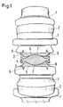
- Fig. 1part of a spine with an endoprosthesis inserted therein is shown in cross section.
- the spineconsists of a large number of vertebral bodies 1, between which intervertebral discs 2 are arranged in healthy people.
- the intervertebral disc between the two middle vertebral bodies 1is replaced by the intervertebral endoprosthesis, which can be used in connection with the instrument set according to the invention.
- the endoprosthesisconsists of two end plates 3 and a sliding body 4 arranged between them.
- the end plate 3On the side facing the vertebral body 1, the end plate 3 has a substantially flat surface 5, which is provided with prong-like projections 6 which penetrate into the vertebral body, and so on to hold the end plates 3 securely on the vertebral body 1.
- the end plates 3are provided with an essentially spherical shell-shaped recess 7.
- the end plates 3are usually made of metal.
- the sliding core 4is arranged, which has corresponding spherical shell-shaped projections 8 to the spherical shell-shaped recesses 7.
- the sliding body 4is usually made of plastic.
- the spreading pliers 9 shown in FIGS. 2 to 6have two spreading jaws 10, 11 arranged in parallel, which can be spread apart by a scissor-like joint 12 with the aid of levers 13, 14 so that their surfaces remain parallel.
- the levers 13, 14are pressed apart by springs 15, so that the expanding jaws 10, 11 are normally compressed. If the levers 13, 14 are pressed together against the force of the spring 15, the expansion jaws 10, 11 are pressed apart.
- the expanding jaws 10, 11are angled relative to the longitudinal direction of the forceps, since this allows the expanding jaws to be guided better into the exposed space between the vertebral bodies. Since large forces are normally required for this purpose, the expansion jaws 10, 11 have a cylindrical recess 18 at their rear end, to which an insertion tool can be attached, which is shown in FIG. 10.
- the spreading jaws 10, 11have at their front end a U-shaped recess 19 into which an end plate 3 can be inserted. In the cross-sectional view of FIG. 5, only one of these end plates 3 is shown.
- the end plates 3are held in grooves 20 which extend along the legs of the U.
- the end plates 3are only held on the edge in corresponding grooves 20 of the expanding jaws 10, 11, which are on one side are beveled.
- the base of the grooveis flat and essentially parallel to the plane of the expanding jaws.
- the expansion jaws 10, 11 in the front part, which is placed between the vertebral bodies,essentially have the thickness of the end plates 3.
- the teeth 6protrude beyond this area. Only behind the area of the expanding jaws that is introduced between the vertebral bodies, do the expanding jaws have a thickening 22 that increases stability.
- a holding instrument 23 for sliding cores 4is shown. 7 is a view. 8 and 9 are cross-sectional representations in two different functional positions.
- the holding instrument 23has an essentially U-shaped holding element, which consists of two legs 24, 25.
- the legsnormally assume the rest position shown in FIG. 8, in which the legs 24, 25 enclose the sliding core 4 only relatively loosely.
- a pulling forceis exerted on a pull rod 29 which is arranged in an outer tube 28 and is connected to the holding element parts 24, 25.
- the holding element parts 24, 25 with beveled surfaces 30abut corresponding beveled surfaces 31 of the tube 28 or an extension The same, so that the two parts 24, 25 are pressed together and hold the sliding core 4.
- FIGS. 10shows a driving instrument 32 which is essentially rod-shaped. At its front end it carries a transverse cylindrical part 33, which can be inserted into the recess 18 of the expanding pliers 9 of FIGS. 2 to 4. If one then holds the driving instrument 32 firmly on the handle 34 and exerts an impact force on the end 35 opposite the cylindrical part 33, the expanding pliers 9 with the end plates arranged thereon can be introduced into the space between the vertebral bodies.
- This instrument 36also has a handle 37 and is widened like a screwdriver to a plate 38 at the other end.
- This plate 38is inserted between the expanding jaws in a position in which the plane of the plate 38 is arranged essentially parallel to the plane of the expanding jaws or at least does not form a too large angle.
- the expanding jawscan then be pressed further apart by rotating the instrument 36.
- FIG. 12a rod-shaped element 39 is shown in FIG. 12, which carries the model of a sliding core 4 at the front. With the help of the instrument 39, you can try out which sliding core size is best suited.
Landscapes
- Health & Medical Sciences (AREA)
- Biomedical Technology (AREA)
- Engineering & Computer Science (AREA)
- Life Sciences & Earth Sciences (AREA)
- Animal Behavior & Ethology (AREA)
- Veterinary Medicine (AREA)
- Heart & Thoracic Surgery (AREA)
- Orthopedic Medicine & Surgery (AREA)
- Surgery (AREA)
- General Health & Medical Sciences (AREA)
- Public Health (AREA)
- Transplantation (AREA)
- Neurology (AREA)
- Molecular Biology (AREA)
- Medical Informatics (AREA)
- Cardiology (AREA)
- Oral & Maxillofacial Surgery (AREA)
- Nuclear Medicine, Radiotherapy & Molecular Imaging (AREA)
- Vascular Medicine (AREA)
- Ophthalmology & Optometry (AREA)
- Physical Education & Sports Medicine (AREA)
- Prostheses (AREA)
- Surgical Instruments (AREA)
Description
Translated fromGermanDie Erfindung betrifft einen chirurgischen Instrumentensatz zum Einsetzen von Zwischenwirbel-Endoprothesen und Zwischenwirbel-Endoprothese, die aus zwei Abschlußplatten und einem dazwischen anzuordnenden Gleitkern besteht, wobei der Instrumentensatz eine Spreizzange aufweist.The invention relates to a surgical instrument set for inserting intervertebral endoprostheses and intervertebral endoprosthesis, which consists of two end plates and a sliding core to be arranged between them, the instrument set having expanding pliers.
Es ist bekannt, in der Wirbelsäule krankhaft veränderte oder nicht mehr funktionsfähige Bandscheiben durch Zwischenwirbel-Endoprothesen zu ersetzen (Artikel von Büttner-Janz, K., Schellnack, K., Zippel, H. "Eine alternative Behandlungsstrategie beim lumbalen Bandscheibenschaden mit der Bandscheibenendoprothese Modulartyp SB Charité", Z. Orthop. 125 (1987), 1-6). Diese Zwischenwirbel-Endoprothesen werden anstelle der vorher entfernten Bandscheibe zwischen die Wirbel eingesetzt. Die beiden Abschlußplatten weisen dabei zackenförmige Vorsprünge auf, durch die sie an den Wirbelkörpern festgehalten werden. Auf ihren zueinander zugewendeten Flächen weisen sie kugelschalenförmige Ausnehmungen auf, zwischen die ein Gleitkern gesetzt wird, der ähnlich geformte kugelschalenförmige Vorsprünge hat. Auf diese Weise ist nach der Operation wieder eine Relativbewegung der Wirbel zueinander möglich. Die Abschlußplatten der Endoprothese bestehen dabei aus Metall, während der Gleitkern aus Kunststoff besteht.It is known to replace intervertebral discs that are pathologically altered or no longer function in the spine by intervertebral endoprostheses (article by Büttner-Janz, K., Schellnack, K., Zippel, H. "An alternative treatment strategy for lumbar disc damage with the modular disc type prosthesis SB Charité ", Z. Orthop. 125 (1987), 1-6). These intervertebral endoprostheses are inserted between the vertebrae instead of the previously removed intervertebral disc. The two end plates have jagged projections through which they are held on the vertebral bodies. On their surfaces facing each other, they have spherical shell-shaped recesses, between which a sliding core is placed, which has similarly shaped spherical shell-shaped projections. In this way, a relative movement of the vertebrae to one another is again possible after the operation. The end plates of the Endoprosthesis are made of metal, while the sliding core is made of plastic.
Ein großes Problem besteht beim Einsetzen dieser Zwischenwirbel-Endoprothesen. Um die Zwischenwirbel-Endoprothese einsetzen zu können, müssen die sich gegenüberstehenden Wirbelkörper auseinandergespreizt werden. Der Einsatz von bekannten Spreizzangen, die üblicherweise für Operationen an der Bandscheibe benutzt werden, würden aber den Platz besetzen, den die Zwischenwirbel-Endoprothese einnehmen soll. Dabei ist zu beachten, daß die Zwischenwirbel-Endoprothese, zur günstigen Lastverteilung, möglichst großflächig, dem Maß der Wirbelkörper entsprechend, aufliegen soll. Ebenfalls erfordert das Auseinanderspreizen der sich gegenüberstehenden Wirbelkörper beträchtliche Kräfte.There is a major problem when inserting these intervertebral endoprostheses. In order to use the intervertebral endoprosthesis, the opposing vertebral bodies must be spread apart. The use of known expanding pliers, which are usually used for operations on the intervertebral disc, would occupy the space that the intervertebral endoprosthesis is supposed to occupy. It should be noted that the intervertebral endoprosthesis should lie on the largest possible area, according to the size of the vertebral bodies, for the best possible distribution of the load. The spreading apart of the opposing vertebral bodies also requires considerable forces.
Mit den bisher üblichen Spreizzangen könnte somit allenfalls nur an den äußeren Rändern der Wirbelkörper angegriffen werden, die nicht von der Zwischenwirbel-Endoprothese besetzt sind. Diese, nur bedingt vorhandenen Knochenflächen der Wirbelkörper, wären aber zum Aufbringen der notwendigen Kräfte zu klein und provozieren damit die Gefahr, daß die Wirbelkörper an diesen Stellen einbrechen.With the usual spreading forceps, it could only be attacked at the outer edges of the vertebral bodies, which are not occupied by the intervertebral endoprosthesis. These bone surfaces of the vertebral bodies, which are only available to a limited extent, would be too small to apply the necessary forces and thus provoke the danger that the vertebral bodies collapse at these points.
Die Aufgabe der Erfindung besteht in der Schaffung eines Instrumentensatzes, mit dem die Endoprothesen bei gleichzeitigem Spreizen der Wirbelkörper und möglichst geringem Risiko des Einbrechens der Wirbelkörper eingesetzt werden können.The object of the invention is to provide a set of instruments with which the endoprostheses can be used with simultaneous spreading of the vertebral bodies and the lowest possible risk of the vertebral bodies collapsing.
Die erfindungsgemäße Lösung besteht darin, daß die Spreizzange an ihrem vorderen Ende an jeder Spreizbacke eine eine Abschlußplatte an drei Seiten umgreifende und am Rand festhaltende im wesentlichen U-förmige Ausnehmung aufweist, wobei die Dicke der Spreizbacken in Spreizrichtung im wesentlichen gleich der Dicke der Abschlußplatten ist.The solution according to the invention consists in that the spreading pliers have at their front end on each expanding jaw a substantially U-shaped recess encompassing an end plate on three sides and retaining at the edge, the thickness of the expanding jaws in the spreading direction being substantially equal to the thickness of the end plates .
Die Abschlußplatten werden also auf drei Seiten von den Spreizbacken umgriffen. Die beiden Abschlußplatten liegen dabei zunächst direkt aufeinander. In dieser Stellung werden dann die Spreizbacken zwischen die beiden Wirbelkörper gebracht. Anschließend erfolgt dann das Spreizen, damit Raum für den Gleitkern geschaffen wird, wobei das Spreizen noch in größerem Ausmaß erfolgen muß, da zunächst der Gleitkern mit seinen Vorsprüngen zwischen die Abschlußplatten eingebracht werden muß.The end plates are therefore encompassed on three sides by the expanding jaws. The two end plates are initially directly on top of each other. In this position, the expanding jaws are then brought between the two vertebrae. The spreading then takes place so that space is created for the sliding core, the spreading still having to be carried out to a greater extent, since first the sliding core with its projections must be inserted between the end plates.
Die dabei auftretenden beträchtlichen Kräfte werden nicht nur auf kleine Bereiche der Wirbelkörper übertragen, sondern großflächig. Diese Kraft wird dabei durch die Abschlußplatten ausgeübt. Auf diese Weise ist mit größtmöglicher Sicherheit das Einbrechen der Wirbelkörper vermieden. Die Wirbelkörper kommen im wesentlichen nur mit den Teilen in Berührung, mit denen sie auch nach der Operation in Berührung stehen, nämlich den Abschlußplatten.The considerable forces that occur are not only transmitted to small areas of the vertebral bodies, but also over a large area. This force is exerted by the end plates. In this way, the collapse of the vertebral bodies is avoided with the greatest possible security. The vertebral bodies essentially only come into contact with the parts with which they are in contact after the operation, namely the end plates.
Zweckmäßigerweise sind die Spreizbacken im Bereich der Innenseiten der Schenkel des U mit Nuten zum Aufnehmen der Abschlußplatten versehen, die in der zur Spreizrichtung senkrechten Ebene angeordnet sind. Dadurch können die Abschlußplatten vom offenen Ende des U seitlich in die Spreizbacken eingeschoben werden. Die großen Spreizkräfte, die auf die Abschlußplatten wirken, werden dabei von den Seitenwänden der Nuten aufgenommen. Die Kraft wirkt dabei nur in einer Richtung, so daß nur eine Nutenwand besonders kräftig ausgebildet sein muß. Durch die äußere Nutenwand muß lediglich das Herausfallen der Abschlußplatten verhindert werden. Hier können die Nutenwände schwächer ausgebildet sein, wobei vorgesehen sein kann, daß die Nuten abgeschrägte Wände aufweisen, da dann auch die Abschlußplatten an den entsprechenden Stellen entsprechend abgeschrägte Wände besitzen können, so daß hier keine scharfen Kanten vorhanden sind.The expanding jaws are expediently provided in the region of the inner sides of the legs of the U with grooves for receiving the end plates, which are arranged in the plane perpendicular to the expanding direction. As a result, the end plates can be inserted laterally into the expansion jaws from the open end of the U. The large spreading forces that act on the end plates are absorbed by the side walls of the grooves. The force acts only in one direction, so that only one groove wall has to be particularly strong. The outer groove wall only has to prevent the end plates from falling out. Here, the groove walls can be made weaker, it being possible for the grooves to have beveled walls, since then the end plates can also have correspondingly beveled walls at the corresponding points, so that there are no sharp edges here.
Damit die Abschlußplatten nicht nach vorne aus der Öffnung des U herausrutschen können, kann bei jeder Spreizbacke an einem vorderen Nutenende eine federnd nachgebende Klinke vorgesehen sein. Ist eine Abschlußplatte in die Spreizbacke eingeschoben, so hindert die federnd nachgebende Klinke dieselbe daran, herauszufallen. Ist andererseits die Endoprothese eingesetzt, so wird die Klinke nachgeben, wenn man die Zange wieder entfernen will.So that the end plates cannot slide forward out of the opening of the U, a resilient pawl can be provided on each spreader jaw at a front groove end. If an end plate is inserted into the expanding jaw, the resilient pawl prevents it from falling out. On the other hand, if the endoprosthesis is inserted, the pawl will give way when you want to remove the forceps.
Zweckmäßigerweise wird man die Abschlußplatten beim Spreizvorgang so auseinanderbewegen, daß ihre an den Wirbelkörpern angreifende Oberflächen parallel bleiben. Daher wird zweckmäßigerweise vorgesehen, daß die Spreizbacken mit einer scherenartigen Parallelführung verbunden sind.Expediently, the end plates will be moved apart during the spreading process so that their surfaces engaging the vertebral bodies remain parallel. It is therefore expediently provided that the expanding jaws are connected with a scissor-like parallel guide.
Zweckmäßigerweise wird man vorsehen, daß die Spreizzange eine lösbare Rasteinrichtung für die gespreizte Stellung aufweist, damit der Operateur nach dem Spreizen die Hände frei hat, um den Gleitkern einzusetzen.Appropriately, it will be provided that the spreading pliers have a releasable locking device for the spread position so that the operator has his hands free after the spreading in order to insert the sliding core.
Das Einschieben der Spreizzange mit den daran angeordneten Abschlußplatten zwischen die Wirbelkörper erfordert verhältnismäßig viel Kraft, die allein durch die Spreizzange sehr schwer oder gar nicht übertragen werden kann. Deswegen ist zweckmäßigerweise vorgesehen, daß die Spreizzange im Bereich der Spreizbacken mit einem Vorsprung oder einer Ausnehmung versehen ist, der bzw. die eine im wesentlichen quer zur Eintreibrichtung ausgerichtete Anschlagf läche für ein im wesentlichen stabförmiges Eintreibinstrument aufweist. Die Kraft zum Einschieben der Spreizzange wird also mit Hilfe eines Eintreibinstruments aufgebracht, mit dem die Eintreibkraft in der richtigen Richtung ausgeübt werden kann, was insbesondere bei abgewinkelten Spreizbacken nicht möglich ist. Die Anschlagfläche kann dabei zylindrischen oder kugelförmigen Querschnitt haben, so daß das Eintreibinstrument unter verschiedenen Winkeln angesetzt werden kann.The insertion of the expanding pliers with the end plates arranged thereon between the vertebral bodies requires a relatively large amount of force, which alone can be transmitted very difficultly or not at all by the expanding pliers. It is therefore expediently provided that the expanding pliers in the region of the expanding jaws are provided with a projection or a recess which has a stop surface for a substantially rod-shaped driving instrument which is oriented essentially transversely to the driving direction. The force for inserting the expanding pliers is therefore applied with the aid of an insertion tool, with which the insertion force can be exerted in the correct direction, which is not possible in particular with angled expansion jaws. The stop surface can have a cylindrical or spherical cross section, so that the driving instrument can be attached at different angles.
Wie bereits erwähnt sind die Spreizkräfte sehr groß. Da die Spreizzange verhältnismäßig lange Hebelarme hat, würde sie sehr unförmig werden, wenn man sie so stabil ausbildet, daß sie in jedem Fall die notwendigen Spreizkräfte ausüben kann. Zweckmäßigerweise ist daher vorgesehen, daß der Instrumentensatz ein im wesentlichen schraubendreherähnliches stabförmiges Element aufweist, das an seinem einen Ende einen Handgriff trägt, wobei das andere Ende die Form einer länglichen Platte hat. Nachdem die Spreizung begonnen worden ist und die Spreizbacken schon einen gewissen Abstand voneinander haben, kann das stabförmige Element zwischen die Backen so eingeführt werden, daß die Ebene der länglichen Platte im wesentlichen zur Ebene der Spreizbacken parallel ist. Wird dann anschließend das stabförmige Element gedreht, so wird genau an der Stelle, an der die Spreizkraft erforderlich wird, eine sehr große Kraft ausgeübt, bis die Ebene der Platte im wesentlichen senkrecht zur Spreizbackenebene steht. In dieser Stellung kann dann das stabförmige Element in der Spreizzange verbleiben, um diese Stellung zu fixieren. Gegebenenfalls kann diese Spreizung schrittweise dadurch erweitert werden, daß man anschließend ein stabförmiges Element mit einer etwas breiteren Platte verwendet, um so allmählich zu größeren Breiten zu kommen.As already mentioned, the spreading forces are very large. Since the spreading pliers have relatively long lever arms, they would become very misshapen if they were made so stable that they can exert the necessary spreading forces in any case. It is therefore expediently provided that the instrument set has an essentially screwdriver-like rod-shaped element which carries a handle at one end, the other end being in the form of an elongated plate. After the spreading has started and the spreading jaws are already a certain distance apart, the rod-shaped element can be inserted between the jaws in such a way that the plane of the elongated plate is essentially parallel to the plane of the spreading jaws. If the rod-shaped element is then subsequently rotated, a very large force is exerted precisely at the point at which the spreading force is required until the plane of the plate is substantially perpendicular to the plane of the spreading jaws. In this position, the rod-shaped element can then remain in the expanding pliers in order to fix this position. If necessary, this spread can be gradually expanded by subsequently using a rod-shaped element with a somewhat wider plate in order to gradually get larger widths.
Statt einer Platte mit im wesentlichen rechteckigem Querschnitt und abgerundeten Kanten könnte man auch z.B. ein ovales Teil verwenden.Instead of a plate with a substantially rectangular cross section and rounded edges, one could also use e.g. use an oval part.
Besonders zweckmäßig können die Gleitkerne eingesetzt werden, wenn der Instrumentensatz ein Halteinstrument für Gleitkerne aufweist, das stabförmig ist und am vorderen Ende mit federnden, dem Gleitkern am Umfang über einen Winkelbereich von etwas mehr als 180° umgreifenden Halteelementen versehen ist.The sliding cores can be used particularly expediently if the instrument set has a holding instrument for sliding cores which is rod-shaped and is provided at the front end with resilient holding elements which encompass the sliding core on the circumference over an angular range of somewhat more than 180 °.
Die federnden Halteelemente halten zunächst den Gleitkern fest. Ist die Spreizung aufgehoben und wird der Gleitkern zwischen den Abschlußplatten festgehalten, so kann das Halteinstrument wieder herausgezogen werden, wobei sich die Halteelemente aufgrund ihrer Federwirkung vom Gleitkern lösen, der am gewünschten Ort verbleibt.The resilient holding elements initially hold the sliding core. If the spread is removed and the sliding core held between the end plates, the holding instrument can be pulled out again, the holding elements detaching due to their spring action from the sliding core, which remains at the desired location.
Zweckmäßigerweise sind zwei einstückig miteinander verbundene Halteelemente vorgesehen, die sich über je einen Winkelbereich von ungefähr 90° erstrecken, die mit einer Stange verbunden sind, die sich durch das rohrförmig ausgebildete Halteinstrument erstreckt, wobei die Halteelemente mit nach vorne auseinanderlaufenden Schrägflächen innen am Rohrende anliegen, und wobei am anderen Ende eine Schraubenanordnung zum Ausüben einer Zugkraft auf die Stange vorgesehen ist. Aufgrund der Federwirkung werden bei dieser Ausführungsform die beiden Halteelemente auseinandergedrückt, so daß sich eine Öffnung bildet, in die der Gleitkern eingeführt werden kann. Wird anschließend eine Zugkraft auf die Stange ausgeübt, so berühren die Schrägflächen innen das Rohr, so daß die Halteelemente gegen die Federkraft aufeinander zugedrückt werden und somit den Gleitkern festhalten. Damit der Gleitkern anschließend aus dem Halteinstrument entfernt werden kann bzw. das Halteinstrument vom Gleitkern abgezogen werden kann, muß dann durch Drehen der Schraubanordnung in der entgegengesetzen Richtung lediglich die Zugkraft aufgehoben werden.Appropriately, two integrally connected holding elements are provided, each of which extends over an angular range of approximately 90 °, which are connected to a rod which extends through the tubular holding instrument, the holding elements abutting on the inside of the tube end with inclined surfaces that diverge towards the front, and a screw arrangement is provided at the other end for exerting a tensile force on the rod. Due to the spring action in this embodiment, the two holding elements are pressed apart, so that an opening is formed, into which the sliding core can be inserted. If a tensile force is then exerted on the rod, the inclined surfaces touch the inside of the tube, so that the holding elements are pressed towards one another against the spring force and thus hold the sliding core in place. So that the sliding core can then be removed from the holding instrument or the holding instrument can be removed from the sliding core, all that then has to be done is to remove the tensile force by turning the screw arrangement in the opposite direction.
Das Halteinstrument ist besonders zweckmäßig im Zusammenhang mit der Spreizzange zu verwenden, kann aber auch für andere Arten des Einsetzens der Endoprothesen verwendet werden. Zur Erfindung gehört daher auch ein Instrumentensatz, der nur ein oder mehrere Halteinstrumente aufweist.The holding instrument is particularly useful in connection with the expanding forceps, but can also be used for other types of insertion of the endoprostheses. The invention therefore also includes an instrument set which has only one or more holding instruments.
Wenn der Instrumentensatz weiterhin ein stangenförmiges Element aufweist, an dem vorne ein Modell eines Gleitkerns befestigt ist, so kann mit diesen Elementen nach Durchführung der Spreizung festgestellt werden, welcher Gleitkern am besten paßt. Zu diesem Zweck wird man selbstverständlich mehrere solcher stangenförmiger Elemente mit unterschiedlichen Gleitkernen verwenden. Man probiert also die richtige Größe mit Modellen von Gleitkernen aus und nicht mit Gleitkernen, von denen dann anschließend einer in der Endoprothese verbleiben soll. Dies ist unter anderem schon aus Gründen der Sterilisierung zweckmäßiger, da ein dauernd im Körper verbleibender Gleitkern sorgfältiger sterilisiert werden muß als ein Modell eines Gleitkerns, der nach kurzer Zeit wieder entfernt wird.If the instrument set also has a rod-shaped element to which a model of a sliding core is attached at the front, these elements can be used to determine which sliding core fits best after the spreading has been carried out. For this purpose one becomes self-evident use several such rod-shaped elements with different sliding cores. So try the right size with models of sliding cores and not with sliding cores, one of which should then remain in the endoprosthesis. Among other things, this is more expedient for reasons of sterilization, since a sliding core that remains permanently in the body must be sterilized more carefully than a model of a sliding core that is removed again after a short time.
Zweckmäßigerweise wird der Instrumentensatz nicht nur mehrere stangenförmige Elemente mit Modellen von Gleitkernen, sondern auch mehrere Spreizzangen, schraubendreherähnliche Spreizelemente und Halteinstrumente für Gleitkerne aufweisen, damit verschieden große Endoprothesen eingesetzt werden können.Expediently, the instrument set will not only have several rod-shaped elements with models of sliding cores, but also several spreading pliers, screwdriver-like spreading elements and holding instruments for sliding cores, so that endoprostheses of different sizes can be used.
Die Erfindung wird im folgenden anhand von vorteilhaften Ausführungsformen unter Bezugnahme auf die beigefügten Zeichnungen beschrieben. Es zeigen:
- Fig. 1
- im Querschnitt eine Zwischenwirbel-Endoprothese, die mit dem erfindungsgemäßen Instrumentensatz eingesetzt werden kann;
- Fig. 2
- eine Spreizzange der Erfindung in Seitenansicht;
- Fig. 3
- ein Detail der Spreizzange der Fig. 2 in Draufsicht;
- Fig. 4
- eine vergrößerte Darstellung des Teiles der Fig. 3;
- Fig. 5
- eine Querschnittsansicht entlang der Linie V-V von Fig. 4;
- Fig. 6
- eine Querschnittsansicht entlang der Linie VI-VI von Fig. 4;
- Fig. 7
- eine Gesamtansicht eines Halteinstruments für Gleitkerne;
- Fig. 8 und 9
- Querschnittsansichten des Instruments der Fig. 7 in verschiedenen arbeitsmäßigen Stellungen;
- Fig. 10
- ein Eintreibinstrument, das mit der Spreizzange der Fig. 2
bis 6 verwendet werden kann; - Fig. 11
- ein zusätzliches schraubendreherförmiges Spreizinstrument;
- Fig. 12
- ein stangenförmiges Element mit einem Modell eines Gleitkerns.
- Fig. 1
- in cross section an intervertebral endoprosthesis that can be used with the instrument set according to the invention;
- Fig. 2
- a spreader of the invention in side view;
- Fig. 3
- a detail of the expanding pliers of Figure 2 in plan view.
- Fig. 4
- an enlarged view of the part of Fig. 3;
- Fig. 5
- a cross-sectional view taken along line VV of Fig. 4;
- Fig. 6
- a cross-sectional view taken along the line VI-VI of Fig. 4;
- Fig. 7
- an overall view of a holding instrument for sliding cores;
- 8 and 9
- Cross-sectional views of the instrument of Figure 7 in various working positions.
- Fig. 10
- a driving tool that can be used with the expanding pliers of Figures 2 to 6;
- Fig. 11
- an additional screwdriver-shaped spreading instrument;
- Fig. 12
- a rod-shaped element with a model of a sliding core.
In Fig. 1 ist im Querschnitt ein Teil einer Wirbelsäule mit darin eingesetzter Endoprothese dargestellt. Die Wirbelsäule besteht aus einer Vielzahl von Wirbelkörpern 1, zwischen denen beim gesunden Menschen Bandscheiben 2 angeordnet sind. Die Bandscheibe zwischen den beiden mittleren Wirbelkörpern 1 ist durch die Zwischenwirbel-Endoprothese ersetzt, die im Zusammenhang mit dem erfindungsgemäßen Instrumentensatz verwendet werden kann. Die Endoprothese besteht aus zwei Abschlußplatten 3 und einem zwischen denselben angeordneten Gleitkörper 4. Auf der zum Wirbelkörper 1 gerichteten Seite weist die Abschlußplatte 3 eine im wesentlichen ebene Oberfläche 5 auf, die mit zackenartigen Vorsprüngen 6 versehen ist, die in den Wirbelkörper eindringen, um so die Abschlußplatten 3 sicher am Wirbelkörper 1 festzuhalten. Auf der gegenüberliegenden Seite sind die Abschlußplatten 3 mit einer im wesentlichen kugelschalenförmigen Ausnehmung 7 versehen. Die Abschlußplatten 3 bestehen normalerweise aus Metall.In Fig. 1, part of a spine with an endoprosthesis inserted therein is shown in cross section. The spine consists of a large number of
Zwischen den Abschlußplatten 3 ist der Gleitkern 4 angeordnet, der zu den kugelschalenförmigen Ausnehmungen 7 entsprechende kugelschalenförmige Vorsprünge 8 aufweist. Der Gleitkörper 4 besteht dabei normalerweise aus Kunststoff.Between the
Die in den Fig. 2 bis 6 gezeigte Spreizzange 9 weist zwei parallel angeordnete Spreizbacken 10, 11 auf, die durch ein scherenartiges Gelenk 12 mit Hilfe von Hebeln 13, 14 so auseinander gespreizt werden können, daß ihre Flächen parallel bleiben. Die Hebel 13, 14 werden dabei durch Federn 15 auseinandergedrückt, so daß die Spreizbacken 10, 11 normalerweise zusammengedrückt sind. Werden gegen die Kraft der Feder 15 die Hebel 13, 14 zusammengedrückt, so werden die Spreizbacken 10, 11 auseinandergedrückt. Dabei rasten Zähne eines Sperrelementes 16, das durch eine Feder 17 in Fig. 2 im Uhrzeigersinn federbelastet ist, in entsprechende Zähne oder Vorsprünge des unteren Hebels 14 ein, so daß die jeweils erreichte Spreizstellung durch das Element 16, das schwenkbar am Hebel 13 befestigt ist, gehalten wird.The spreading
Wie dies in Fig. 3 ersichtlich ist, sind die Spreizbacken 10, 11 relativ zur Zangenlängsrichtung abgewinkelt, da man so die Spreizbacken besser in den freigelegten Raum zwischen die Wirbelkörper führen kann. Da hierzu normalerweise große Kräfte nötig sind, weisen die Spreizbacken 10, 11 an ihrem hinteren Ende eine zylinderförmige Ausnehmung 18 auf, an der ein Eintreibinstrument angesetzt werden kann, das in Fig. 10 gezeigt ist.As can be seen in FIG. 3, the expanding
Die Spreizbacken 10, 11 weisen an ihrem vorderen Ende eine U-förmige Ausnehmung 19 auf, in die eine Abschlußplatte 3 eingesetzt werden kann. In der Querschnittsansicht der Fig. 5 ist dabei nur eine dieser Abschlußplatten 3 dargestellt. Die Abschlußplatten 3 werden in Nuten 20 gehalten, die sich entlang der Schenkel des U erstrecken. Die Abschlußplatten 3 werden dabei lediglich am Rand in entsprechenden Nuten 20 der Spreizbacken 10, 11 festgehalten, die auf einer Seite abgeschrägt sind. Auf der Seite, auf der durch die Abschlußplatten 3 die größte Kraft ausgeübt ist, ist der Nutgrund aber eben und im wesentlichen parallel zur Spreizbackenebene.The spreading
In den Fig. 4 bis 6 erkennt man noch eine federnde Klinke 21, die den Nutausgang normalerweise verschließt und dadurch eine dort eingeschlossene Abschlußplatte 3 festhält. Diese federnde Klinke 21 gibt aber nach, wenn gewollt eine Abschlußplatte in die Nut 20 hineingesteckt werden soll oder die Spreizzange nach Einbringen der Endoprothese abgezogen werden soll.4 to 6 you can still see a
Wie man aus den Fig. 4 bis 6 erkennt, haben die Spreizbacken 10, 11 im vorderen Teil, der zwischen die Wirbelkörper verbracht wird, im wesentlichen die Dicke der Abschlußplatten 3. Die Zähne 6 ragen dabei über diesen Bereich heraus. Erst hinter dem Bereich der Spreizbacken, der zwischen die Wirbelkörper eingebracht wird, haben die Spreizbacken eine die Stabilität erhöhende Verdickung 22.As can be seen from FIGS. 4 to 6, the
In den Fig. 7 bis 9 ist ein Halteinstrument 23 für Gleitkerne 4 dargestellt. Fig. 7 ist dabei eine Ansicht. Fig. 8 und 9 sind Querschnittsdarstellungen in zwei verschiedenen Funktionsstellungen.7 to 9, a holding
Das Halteinstrument 23 weist ein im wesentlichen U-förmiges Halteelement auf, das aus zwei Schenkeln 24, 25 besteht. Die Schenkel nehmen dabei normalerweise die in Fig. 8 gezeigte Ruhelage ein, bei der die Schenkel 24, 25 den Gleitkern 4 nur verhältnismäßig lose umfassen. Wird aber an der Schraube 26 am hinteren Ende eines Handgriffes 27 gedreht, so wird auf eine in einem Außenrohr 28 angeordnete Zugstange 29, die mit den Halteelementteilen 24, 25 verbunden ist, eine Zugkraft ausgeübt. Dadurch stoßen die Halteelementteile 24, 25 mit abgeschrägten Flächen 30 gegen entsprechende abgeschrägte Flächen 31 des Rohres 28 bzw. eines Ansatzes an demselben, so daß die beiden Teile 24, 25 zusammengedrückt werden und den Gleitkern 4 festhalten.The holding
In Fig. 10 ist ein Eintreibinstrument 32 gezeigt, das im wesentlichen stabförmig ausgebildet ist. An seinem vorderen Ende trägt es ein querstehendes zylindrisches Teil 33, das in die Ausnehmung 18 der Spreizzange 9 der Fig. 2 bis 4 eingesetzt werden kann. Hält man dann das Eintreibinstrument 32 am Handgriff 34 fest und übt eine Schlagkraft auf das dem zylindrischen Teil 33 entgegengesetzte Ende 35 auf, so kann die Spreizzange 9 mit den daran angeordneten Abschlußplatten in den Raum zwischen den Wirbelkörpern eingebracht werden.10 shows a driving
Nachdem die Spreizung bis zu einem gewissen Ausmaß vorgenommen worden ist, kann die weitere Spreizung mit Hilfe des Instrumentes 36 der Fig. 11 erfolgen. Dieses Instrument 36 besitzt ebenfalls einen Handgriff 37 und ist am anderen Ende schraubendreherartig zu einer Platte 38 verbreitert. Diese Platte 38 wird zwischen die Spreizbacken in einer Stellung eingebracht, in der die Ebene der Platte 38 im wesentlichen parallel zur Ebene der Spreizbacken angeordnet ist oder zumindest keinen allzu großen Winkel einschließt. Durch Drehen des Instruments 36 können dann die Spreizbacken weiter auseinandergedrückt werden.After the spreading has been carried out to a certain extent, the further spreading can take place with the aid of the
In Fig. 12 ist schließlich noch ein stangenförmiges Element 39 gezeigt, das vorne das Modell eines Gleitkerns 4 trägt. Mit Hilfe des Instruments 39 kann durch Probieren herausgestellt werden, welche Gleitkerngröße am besten geeignet ist.Finally, a rod-shaped
Claims (12)
- Surgical instrument set for the insertion of intervertebral endoprostheses and intervertebral endoprosthesis, consisting of two closing plates (3) and a sliding core (4) to be located between the latter, the instrument set containing expansion forceps (9), characterised in that the expansion forceps have an essentially U-shaped recess (19) at their front end on each expansion jaw (10, 11), which grips a closing plate (3) on three sides and holds it fast on the edge, the thickness of the expansion jaws (10, 11) in the direction of expansion being essentially equal to the thickness of the closing plates (3).
- Surgical instrument set in accordance with Claim 1, characterised in that the expansion jaws (10, 11) are provided with grooves (20) in the vicinity of the internal sides of the sides of the U, to take up the closing plates (3), these grooves being located in the plane perpendicular to the direction of expansion.
- Surgical instrument set in accordance with Claim 2, characterised in that the grooves (20) have bevelled sides.
- Surgical instrument set in accordance with Claims 1 or 2, characterised in that a spring-action catch (21) is provided on the front end of a groove on each expansion jaw (10, 11).
- Surgical instrument set in accordance with one of Claims 1 to 4, characterised in that the expansion jaws (10, 11) are joined by a scissor-type parallel guide (12).
- Surgical instrument set in accordance with one of Claims 1 to 4, characterised in that the expansion forceps (9) have a detachable catching device (16, 17) for the expanded position.
- Surgical instrument set in accordance with one of Claims 1 to 6, characterised in that the expansion forceps (9) are fitted, in the vicinity of the expansion jaws (10, 11), with a projection or recess (18) having a stop face aligned basically transverse to the driving direction for a basically bar-shaped driving instrument (32).
- Surgical instrument set in accordance with one of Claims 1 to 7, characterised in that it contains a bar-shaped element (36), essentially similar to a screwdriver, with a handle (37) at one end and having the shape of an oblong plate (38) at the other end.
- Surgical instrument set in accordance with one of Claims 1 to 8, characterised in that it contains a holding instrument (23) for sliding cores (4), which is bar-shaped and is fitted at the front end with sprung holding pieces (24, 25) which grip the circumference of the sliding core (4) over an angle of slightly more than 180°.
- Surgical instrument set in accordance with Claim 9, characterised in that two single-piece, interconnected holding pieces (24, 25) are provided, each extending over an angle of about 90°, connected by a rod (29), which extends through the holding instrument (23) which is tubular in design (at 28), in that the holding pieces (24, 25) sit inside the end of the tube with slanting surfaces (30) diverging to the front and in that a screw arrangement (26) is provided at the other end to exert traction on the rod (29).
- Surgical instrument set in accordance with one of Claims 1 to 10, characterised in that it contains a rod-shaped element (39) on the front of which a model of a sliding core is fixed.
- Surgical instrument set in accordance with one of Claims 1 to 11, characterised in that it contains instruments (9, 23, 32, 36, 39) of different sizes.
Applications Claiming Priority (2)
| Application Number | Priority Date | Filing Date | Title |
|---|---|---|---|
| DE3809793ADE3809793A1 (en) | 1988-03-23 | 1988-03-23 | SURGICAL INSTRUMENT SET |
| DE3809793 | 1988-03-23 |
Publications (3)
| Publication Number | Publication Date |
|---|---|
| EP0333990A2 EP0333990A2 (en) | 1989-09-27 |
| EP0333990A3 EP0333990A3 (en) | 1990-05-09 |
| EP0333990B1true EP0333990B1 (en) | 1993-07-21 |
Family
ID=6350492
Family Applications (1)
| Application Number | Title | Priority Date | Filing Date |
|---|---|---|---|
| EP89101147AExpired - LifetimeEP0333990B1 (en) | 1988-03-23 | 1989-01-23 | Surgical instrument set |
Country Status (4)
| Country | Link |
|---|---|
| US (2) | US4997432A (en) |
| EP (1) | EP0333990B1 (en) |
| DE (2) | DE3809793A1 (en) |
| ES (1) | ES2042814T3 (en) |
Cited By (25)
| Publication number | Priority date | Publication date | Assignee | Title |
|---|---|---|---|---|
| FR2659226A1 (en)* | 1990-03-07 | 1991-09-13 | Jbs Sa | PROSTHESIS FOR INTERVERTEBRAL DISCS AND ITS IMPLANTATION INSTRUMENTS. |
| US5782830A (en)* | 1995-10-16 | 1998-07-21 | Sdgi Holdings, Inc. | Implant insertion device |
| US6245072B1 (en) | 1995-03-27 | 2001-06-12 | Sdgi Holdings, Inc. | Methods and instruments for interbody fusion |
| EP1222903A1 (en) | 2001-01-12 | 2002-07-17 | Waldemar Link (GmbH & Co.) | Surgical instrument for implanting an intervertebral prosthesis |
| US7803162B2 (en) | 2003-07-21 | 2010-09-28 | Spine Solutions, Inc. | Instruments and method for inserting an intervertebral implant |
| US8048084B2 (en) | 2004-09-08 | 2011-11-01 | Aesculap Ag | Surgical instrument |
| US8105381B2 (en) | 2002-12-13 | 2012-01-31 | Spine Solutions, Inc. | Intervertebral implant, insertion tool and method of inserting same |
| US8123757B2 (en) | 2003-12-31 | 2012-02-28 | Depuy Spine, Inc. | Inserter instrument and implant clip |
| US8257439B2 (en) | 2004-12-22 | 2012-09-04 | Ldr Medical | Intervertebral disc prosthesis |
| US8267999B2 (en) | 2002-11-05 | 2012-09-18 | Ldr Medical | Intervertebral disc prosthesis |
| US8337500B2 (en) | 2006-07-31 | 2012-12-25 | Synthes Usa, Llc | Drilling/milling guide and keel cut preparation system |
| US8343219B2 (en) | 2007-06-08 | 2013-01-01 | Ldr Medical | Intersomatic cage, intervertebral prosthesis, anchoring device and implantation instruments |
| US8465546B2 (en) | 2007-02-16 | 2013-06-18 | Ldr Medical | Intervertebral disc prosthesis insertion assemblies |
| US8506634B2 (en) | 1999-07-02 | 2013-08-13 | DePuy Synthes Products, LLC | Intervertebral implant |
| US8535326B2 (en) | 1999-09-14 | 2013-09-17 | DePuy Synthes Products, LLC | Insertion instrument for an intervertebral implant |
| US8585710B2 (en) | 2004-09-08 | 2013-11-19 | Aesculap Ag | Surgical instrument for determining the size of intervertebral implant |
| US8663229B2 (en) | 2003-04-28 | 2014-03-04 | DePuy Synthes Products, LLC | Instruments and method for preparing an intervertebral space for receiving an artificial disc implant |
| US8764833B2 (en) | 2008-03-11 | 2014-07-01 | Spinalmotion, Inc. | Artificial intervertebral disc with lower height |
| US8858635B2 (en) | 2004-02-04 | 2014-10-14 | Ldr Medical | Intervertebral disc prosthesis |
| US8906033B2 (en) | 2009-03-30 | 2014-12-09 | DePuy Synthes Products, LLC | Cervical motion disc inserter |
| US8998990B2 (en) | 2006-07-24 | 2015-04-07 | DePuy Synthes Products, LLC | Intervertebral implant with keel |
| US9011544B2 (en) | 2008-05-05 | 2015-04-21 | Simplify Medical, Inc. | Polyaryletherketone artificial intervertebral disc |
| US9011450B2 (en) | 2012-08-08 | 2015-04-21 | DePuy Synthes Products, LLC | Surgical instrument |
| US9333095B2 (en) | 2001-05-04 | 2016-05-10 | Ldr Medical | Intervertebral disc prosthesis, surgical methods, and fitting tools |
| US9504578B2 (en) | 2011-04-06 | 2016-11-29 | Depuy Synthes Products, Inc | Revision hip prosthesis having an implantable distal stem component |
Families Citing this family (563)
| Publication number | Priority date | Publication date | Assignee | Title |
|---|---|---|---|---|
| US7534254B1 (en) | 1988-06-13 | 2009-05-19 | Warsaw Orthopedic, Inc. | Threaded frusto-conical interbody spinal fusion implants |
| US6923810B1 (en)* | 1988-06-13 | 2005-08-02 | Gary Karlin Michelson | Frusto-conical interbody spinal fusion implants |
| US7491205B1 (en) | 1988-06-13 | 2009-02-17 | Warsaw Orthopedic, Inc. | Instrumentation for the surgical correction of human thoracic and lumbar spinal disease from the lateral aspect of the spine |
| US5484437A (en) | 1988-06-13 | 1996-01-16 | Michelson; Gary K. | Apparatus and method of inserting spinal implants |
| US5015247A (en) | 1988-06-13 | 1991-05-14 | Michelson Gary K | Threaded spinal implant |
| US6210412B1 (en) | 1988-06-13 | 2001-04-03 | Gary Karlin Michelson | Method for inserting frusto-conical interbody spinal fusion implants |
| EP0703757B1 (en) | 1988-06-13 | 2003-08-27 | Karlin Technology, Inc. | Apparatus for inserting spinal implants |
| US6123705A (en) | 1988-06-13 | 2000-09-26 | Sdgi Holdings, Inc. | Interbody spinal fusion implants |
| US7431722B1 (en) | 1995-02-27 | 2008-10-07 | Warsaw Orthopedic, Inc. | Apparatus including a guard member having a passage with a non-circular cross section for providing protected access to the spine |
| USD377093S (en) | 1994-05-27 | 1996-12-31 | Michelson Gary K | Spinal distractor |
| US7452359B1 (en) | 1988-06-13 | 2008-11-18 | Warsaw Orthopedic, Inc. | Apparatus for inserting spinal implants |
| US5772661A (en) | 1988-06-13 | 1998-06-30 | Michelson; Gary Karlin | Methods and instrumentation for the surgical correction of human thoracic and lumbar spinal disease from the antero-lateral aspect of the spine |
| US6120502A (en)* | 1988-06-13 | 2000-09-19 | Michelson; Gary Karlin | Apparatus and method for the delivery of electrical current for interbody spinal arthrodesis |
| US6770074B2 (en) | 1988-06-13 | 2004-08-03 | Gary Karlin Michelson | Apparatus for use in inserting spinal implants |
| US5609635A (en)* | 1988-06-28 | 1997-03-11 | Michelson; Gary K. | Lordotic interbody spinal fusion implants |
| US5192327A (en)* | 1991-03-22 | 1993-03-09 | Brantigan John W | Surgical prosthetic implant for vertebrae |
| US5306307A (en)* | 1991-07-22 | 1994-04-26 | Calcitek, Inc. | Spinal disk implant |
| US5320644A (en)* | 1991-08-30 | 1994-06-14 | Sulzer Brothers Limited | Intervertebral disk prosthesis |
| US5235966A (en)* | 1991-10-17 | 1993-08-17 | Jay Jamner | Endoscopic retractor |
| US5258031A (en)* | 1992-01-06 | 1993-11-02 | Danek Medical | Intervertebral disk arthroplasty |
| US5425773A (en)* | 1992-01-06 | 1995-06-20 | Danek Medical, Inc. | Intervertebral disk arthroplasty device |
| US5306309A (en)* | 1992-05-04 | 1994-04-26 | Calcitek, Inc. | Spinal disk implant and implantation kit |
| US5545226A (en)* | 1992-05-29 | 1996-08-13 | Porex Technologies Corp. | Implants for cranioplasty |
| US5281223A (en)* | 1992-09-21 | 1994-01-25 | Ray R Charles | Tool and method for derotating scoliotic spine |
| US5246458A (en)* | 1992-10-07 | 1993-09-21 | Graham Donald V | Artificial disk |
| US5484440A (en)* | 1992-11-03 | 1996-01-16 | Zimmer, Inc. | Bone screw and screwdriver |
| US5676701A (en)* | 1993-01-14 | 1997-10-14 | Smith & Nephew, Inc. | Low wear artificial spinal disc |
| ATE263511T1 (en) | 1993-06-10 | 2004-04-15 | Karlin Technology Inc | PROTECTIVE DEVICE WITH TWO PASSAGES FOR SURGERY OF THE INTERVERBEL SPACE |
| DE4328690B4 (en)* | 1993-08-26 | 2006-08-17 | SDGI Holdings, Inc., Wilmington | Intervertebral implant for vertebral body blocking and implantation instrument for positioning the intervertebral implant |
| FR2709248B1 (en)* | 1993-08-27 | 1995-09-29 | Martin Jean Raymond | Ancillary equipment for placing a spinal instrumentation. |
| CN1156255C (en)* | 1993-10-01 | 2004-07-07 | 美商-艾克罗米德公司 | Spinal implant |
| US5431658A (en)* | 1994-02-14 | 1995-07-11 | Moskovich; Ronald | Facilitator for vertebrae grafts and prostheses |
| US5545168A (en)* | 1994-03-11 | 1996-08-13 | Burke; Dennis W. | Apparatus for both tensioning and crimping a surgical wire |
| FR2717068B1 (en)* | 1994-03-14 | 1996-04-26 | Biomat | Vertebral interbody fusion cage. |
| CA2144211C (en)* | 1994-03-16 | 2005-05-24 | David T. Green | Surgical instruments useful for endoscopic spinal procedures |
| US5620458A (en)* | 1994-03-16 | 1997-04-15 | United States Surgical Corporation | Surgical instruments useful for endoscopic spinal procedures |
| US5531750A (en)* | 1994-07-15 | 1996-07-02 | Snap-On Incorporated | Surgical tool and adjustable locking handle therefor |
| US5674296A (en)* | 1994-11-14 | 1997-10-07 | Spinal Dynamics Corporation | Human spinal disc prosthesis |
| CN1134810A (en) | 1995-02-17 | 1996-11-06 | 索发默达纳集团股份有限公司 | Improved interbody spinal fusion implants |
| US6758849B1 (en) | 1995-02-17 | 2004-07-06 | Sdgi Holdings, Inc. | Interbody spinal fusion implants |
| AU705930B2 (en)* | 1995-03-27 | 1999-06-03 | Warsaw Orthopedic, Inc. | Interbody fusion device and method for restoration of normal spinal anatomy |
| US7291149B1 (en) | 1995-06-07 | 2007-11-06 | Warsaw Orthopedic, Inc. | Method for inserting interbody spinal fusion implants |
| US5769781A (en)* | 1995-11-13 | 1998-06-23 | Chappuis; James L. | Protector retractor |
| US5746768A (en)* | 1996-01-25 | 1998-05-05 | Biomet, Inc. | Scissor action low profile surgical hand instrument |
| US5865845A (en)* | 1996-03-05 | 1999-02-02 | Thalgott; John S. | Prosthetic intervertebral disc |
| US5743918A (en)* | 1996-05-13 | 1998-04-28 | Wright Medical Technology, Inc. | Instrumentation for and method for implanting a spherical prosthesis |
| US5895428A (en)* | 1996-11-01 | 1999-04-20 | Berry; Don | Load bearing spinal joint implant |
| US6902566B2 (en)* | 1997-01-02 | 2005-06-07 | St. Francis Medical Technologies, Inc. | Spinal implants, insertion instruments, and methods of use |
| US7959652B2 (en) | 2005-04-18 | 2011-06-14 | Kyphon Sarl | Interspinous process implant having deployable wings and method of implantation |
| US7306628B2 (en)* | 2002-10-29 | 2007-12-11 | St. Francis Medical Technologies | Interspinous process apparatus and method with a selectably expandable spacer |
| US20080039859A1 (en)* | 1997-01-02 | 2008-02-14 | Zucherman James F | Spine distraction implant and method |
| US20020143331A1 (en)* | 1998-10-20 | 2002-10-03 | Zucherman James F. | Inter-spinous process implant and method with deformable spacer |
| US20080027552A1 (en)* | 1997-01-02 | 2008-01-31 | Zucherman James F | Spine distraction implant and method |
| US7201751B2 (en)* | 1997-01-02 | 2007-04-10 | St. Francis Medical Technologies, Inc. | Supplemental spine fixation device |
| US6068630A (en)* | 1997-01-02 | 2000-05-30 | St. Francis Medical Technologies, Inc. | Spine distraction implant |
| US7101375B2 (en) | 1997-01-02 | 2006-09-05 | St. Francis Medical Technologies, Inc. | Spine distraction implant |
| US6712819B2 (en)* | 1998-10-20 | 2004-03-30 | St. Francis Medical Technologies, Inc. | Mating insertion instruments for spinal implants and methods of use |
| JP3311287B2 (en)* | 1997-01-16 | 2002-08-05 | 旭光学工業株式会社 | Surgical forceps under endoscopic observation |
| WO1998034552A1 (en) | 1997-02-06 | 1998-08-13 | Surgical Dynamics | Expandable non-threaded spinal fusion device |
| AU6329498A (en)* | 1997-02-13 | 1998-09-08 | Boston Scientific Ireland Limited, Barbados Head Office | Percutaneous and hiatal devices and methods for use in minimally invasive pelvicsurgery |
| AU6171798A (en)* | 1997-02-13 | 1998-09-08 | Boston Scientific Ireland Limited, Barbados Head Office | Method and apparatus for minimally invasive pelvic surgery |
| US5851211A (en)* | 1997-04-22 | 1998-12-22 | Khoury; Jamil Al | Suture needle holder method and apparatus |
| US6042582A (en)* | 1997-05-20 | 2000-03-28 | Ray; Charles D. | Instrumentation and method for facilitating insertion of spinal implant |
| US6086595A (en)* | 1997-08-29 | 2000-07-11 | Sulzer Spine-Tech Inc. | Apparatus and method for spinal stabilization |
| US5824094A (en) | 1997-10-17 | 1998-10-20 | Acromed Corporation | Spinal disc |
| US20010016773A1 (en)* | 1998-10-15 | 2001-08-23 | Hassan Serhan | Spinal disc |
| US6139579A (en) | 1997-10-31 | 2000-10-31 | Depuy Motech Acromed, Inc. | Spinal disc |
| US6159215A (en)* | 1997-12-19 | 2000-12-12 | Depuy Acromed, Inc. | Insertion instruments and method for delivering a vertebral body spacer |
| US6086613A (en)* | 1997-12-23 | 2000-07-11 | Depuy Acromed, Inc. | Spacer assembly for use in spinal surgeries |
| US6482233B1 (en) | 1998-01-29 | 2002-11-19 | Synthes(U.S.A.) | Prosthetic interbody spacer |
| WO1999049818A1 (en) | 1998-03-30 | 1999-10-07 | Marchosky J Alexander | Prosthetic system |
| US6835208B2 (en)* | 1998-03-30 | 2004-12-28 | J. Alexander Marchosky | Prosthetic system |
| DE69920896T2 (en) | 1998-04-23 | 2005-11-17 | Boston Scientific Ltd., St. Michael | MEDICAL DEVICE WHICH ENABLES ACCESS TO THE BODY |
| US6019792A (en) | 1998-04-23 | 2000-02-01 | Cauthen Research Group, Inc. | Articulating spinal implant |
| WO1999053871A1 (en) | 1998-04-23 | 1999-10-28 | Cauthen Research Group, Inc. | Articulating spinal implant |
| US6679915B1 (en) | 1998-04-23 | 2004-01-20 | Sdgi Holdings, Inc. | Articulating spinal implant |
| US6296664B1 (en) | 1998-06-17 | 2001-10-02 | Surgical Dynamics, Inc. | Artificial intervertebral disc |
| US6136031A (en) | 1998-06-17 | 2000-10-24 | Surgical Dynamics, Inc. | Artificial intervertebral disc |
| WO2000004851A1 (en) | 1998-07-22 | 2000-02-03 | Spinal Dynamics Corporation | Threaded cylindrical multidiscoid single or multiple array disc prosthesis |
| US6126660A (en)* | 1998-07-29 | 2000-10-03 | Sofamor Danek Holdings, Inc. | Spinal compression and distraction devices and surgical methods |
| US6749635B1 (en) | 1998-09-04 | 2004-06-15 | Sdgi Holdings, Inc. | Peanut spectacle multi discoid thoraco-lumbar disc prosthesis |
| WO2000013619A1 (en)* | 1998-09-04 | 2000-03-16 | Spinal Dynamics Corporation | Peanut spectacle multi discoid thoraco-lumbar disc prosthesis |
| EP1808133B1 (en) | 1998-10-02 | 2008-11-12 | Synthes GmbH | Spinal disc space distractor |
| AU760821B2 (en)* | 1998-10-02 | 2003-05-22 | Synthes Gmbh | Spinal disc space distractor |
| US7029473B2 (en)* | 1998-10-20 | 2006-04-18 | St. Francis Medical Technologies, Inc. | Deflectable spacer for use as an interspinous process implant and method |
| US7189234B2 (en)* | 1998-10-20 | 2007-03-13 | St. Francis Medical Technologies, Inc. | Interspinous process implant sizer and distractor with a split head and size indicator and method |
| WO2000023015A1 (en)* | 1998-10-22 | 2000-04-27 | Sdgi Holdings, Inc. | Artificial intervertebral joint permitting translational and rotational motion |
| US6113637A (en) | 1998-10-22 | 2000-09-05 | Sofamor Danek Holdings, Inc. | Artificial intervertebral joint permitting translational and rotational motion |
| US6193757B1 (en) | 1998-10-29 | 2001-02-27 | Sdgi Holdings, Inc. | Expandable intervertebral spacers |
| DE19900681B4 (en)* | 1999-01-04 | 2007-04-12 | Sartorius Ag | Use of anion exchange membranes to remove endotoxins from nucleic acid containing solutions |
| US6325827B1 (en)* | 1999-02-01 | 2001-12-04 | Blacksheep Technologies, Inc. | Intervertebral implant |
| US6113638A (en)* | 1999-02-26 | 2000-09-05 | Williams; Lytton A. | Method and apparatus for intervertebral implant anchorage |
| US6241770B1 (en) | 1999-03-05 | 2001-06-05 | Gary K. Michelson | Interbody spinal fusion implant having an anatomically conformed trailing end |
| WO2000054662A1 (en)* | 1999-03-16 | 2000-09-21 | The University Of Sydney | Device for use in surgery |
| US6582451B1 (en) | 1999-03-16 | 2003-06-24 | The University Of Sydney | Device for use in surgery |
| EP1198208B1 (en)* | 1999-05-05 | 2013-07-10 | Warsaw Orthopedic, Inc. | Nested interbody spinal fusion implants |
| AU770261B2 (en)* | 1999-06-04 | 2004-02-19 | Warsaw Orthopedic, Inc. | Artificial disc implant |
| DE29910761U1 (en)* | 1999-06-19 | 2000-11-23 | Mathys Medizinaltechnik Ag, Bettlach | Ligament tensioning device for non-spherical joints |
| FR2897259B1 (en) | 2006-02-15 | 2008-05-09 | Ldr Medical Soc Par Actions Si | INTERSOMATIC TRANSFORAMINAL CAGE WITH INTERBREBAL FUSION GRAFT AND CAGE IMPLANTATION INSTRUMENT |
| US6830570B1 (en) | 1999-10-21 | 2004-12-14 | Sdgi Holdings, Inc. | Devices and techniques for a posterior lateral disc space approach |
| WO2001028469A2 (en) | 1999-10-21 | 2001-04-26 | Sdgi Holdings, Inc. | Devices and techniques for a posterior lateral disc space approach |
| DE10014401C2 (en)* | 1999-11-25 | 2001-10-04 | Steinicke Maschinen Und Werkze | Puller for loosening individual parts of an endoprosthesis |
| NZ518391A (en)* | 1999-12-10 | 2004-05-28 | Synthes Ag | Device for distracting or compressing bones or bone parts |
| US6319257B1 (en) | 1999-12-20 | 2001-11-20 | Kinamed, Inc. | Inserter assembly |
| US20020120280A1 (en)* | 1999-12-21 | 2002-08-29 | Securos, Inc. | Crimping device for cranial cruciate ligament stabilization |
| US6383200B1 (en)* | 1999-12-21 | 2002-05-07 | Securos, Inc. | Tensioning device for cranial cruciate ligament stabilization |
| ATE390100T1 (en)* | 2000-02-22 | 2008-04-15 | Warsaw Orthopedic Inc | SPINAL IMPLANT AND INTRODUCTION DEVICE |
| CA2394663A1 (en)* | 2000-02-28 | 2001-09-07 | Sdgi Holdings, Inc. | Articulating spinal implant |
| US6296665B1 (en) | 2000-03-20 | 2001-10-02 | Electro-Biology, Inc. | Method and apparatus for spinal fixation |
| US7462195B1 (en) | 2000-04-19 | 2008-12-09 | Warsaw Orthopedic, Inc. | Artificial lumbar interbody spinal implant having an asymmetrical leading end |
| US6350283B1 (en) | 2000-04-19 | 2002-02-26 | Gary K. Michelson | Bone hemi-lumbar interbody spinal implant having an asymmetrical leading end and method of installation thereof |
| AU2001259593A1 (en)* | 2000-05-05 | 2001-11-20 | Osteotech, Inc. | Intervertebral distractor and implant insertion instrument |
| US6478800B1 (en) | 2000-05-08 | 2002-11-12 | Depuy Acromed, Inc. | Medical installation tool |
| FR2808995B1 (en) | 2000-05-18 | 2003-02-21 | Aesculap Sa | INTERSOMATIC CAGE WITH UNIFIED GRAFT |
| CA2429246C (en)* | 2000-08-08 | 2011-06-07 | Vincent Bryan | Implantable joint prosthesis |
| JP2004516044A (en) | 2000-08-08 | 2004-06-03 | エスディージーアイ・ホールディングス・インコーポレーテッド | Method and apparatus for improving stereotactic body transplantation |
| US7601174B2 (en)* | 2000-08-08 | 2009-10-13 | Warsaw Orthopedic, Inc. | Wear-resistant endoprosthetic devices |
| US7125380B2 (en)* | 2000-08-08 | 2006-10-24 | Warsaw Orthopedic, Inc. | Clamping apparatus and methods |
| US6458159B1 (en)* | 2000-08-15 | 2002-10-01 | John S. Thalgott | Disc prosthesis |
| US7226480B2 (en)* | 2000-08-15 | 2007-06-05 | Depuy Spine, Inc. | Disc prosthesis |
| US7204851B2 (en) | 2000-08-30 | 2007-04-17 | Sdgi Holdings, Inc. | Method and apparatus for delivering an intervertebral disc implant |
| US7503936B2 (en)* | 2000-08-30 | 2009-03-17 | Warsaw Orthopedic, Inc. | Methods for forming and retaining intervertebral disc implants |
| US20050154463A1 (en)* | 2000-08-30 | 2005-07-14 | Trieu Hal H. | Spinal nucleus replacement implants and methods |
| US20020026244A1 (en) | 2000-08-30 | 2002-02-28 | Trieu Hai H. | Intervertebral disc nucleus implants and methods |
| CA2549320A1 (en) | 2000-08-30 | 2002-03-07 | Sdgi Holdings, Inc. | Intervertebral disc nucleus implants and methods |
| US6733531B1 (en) | 2000-10-20 | 2004-05-11 | Sdgi Holdings, Inc. | Anchoring devices and implants for intervertebral disc augmentation |
| US6562045B2 (en) | 2001-02-13 | 2003-05-13 | Sdgi Holdings, Inc. | Machining apparatus |
| US7563285B2 (en)* | 2001-07-16 | 2009-07-21 | Spinecore, Inc. | Artificial intervertebral disc utilizing a ball joint coupling |
| US7223291B2 (en)* | 2001-07-16 | 2007-05-29 | Spinecore, Inc. | Intervertebral spacer device having engagement hole pairs for manipulation using a surgical tool |
| US7115132B2 (en) | 2001-07-16 | 2006-10-03 | Spinecore, Inc. | Static trials and related instruments and methods for use in implanting an artificial intervertebral disc |
| US7169182B2 (en)* | 2001-07-16 | 2007-01-30 | Spinecore, Inc. | Implanting an artificial intervertebral disc |
| US20030069642A1 (en)* | 2001-10-04 | 2003-04-10 | Ralph James D. | Artificial intervertebral disc having a flexible wire mesh vertebral body contact element |
| US6669730B2 (en) | 2001-02-15 | 2003-12-30 | Spinecore, Inc. | Intervertebral spacer device utilizing a spirally slotted belleville washer having radially extending grooves |
| US8940047B2 (en)* | 2001-02-15 | 2015-01-27 | Spinecore, Inc. | Intervertebral spacer device having recessed notch pairs for manipulation using a surgical tool |
| US20050125064A1 (en)* | 2001-02-15 | 2005-06-09 | Spinecore, Inc. | Intervertebral spacer device |
| US7575576B2 (en)* | 2001-07-16 | 2009-08-18 | Spinecore, Inc. | Wedge ramp distractor and related methods for use in implanting artificial intervertebral discs |
| US7235081B2 (en)* | 2001-07-16 | 2007-06-26 | Spinecore, Inc. | Wedge plate inserter/impactor and related methods for use in implanting an artificial intervertebral disc |
| US7604664B2 (en) | 2001-07-16 | 2009-10-20 | Spinecore, Inc. | Spinal baseplates with ball joint coupling and a retaining member |
| US8858564B2 (en)* | 2001-02-15 | 2014-10-14 | Spinecore, Inc. | Wedge plate inserter/impactor and related methods for use in implanting an artificial intervertebral disc |
| US6989032B2 (en)* | 2001-07-16 | 2006-01-24 | Spinecore, Inc. | Artificial intervertebral disc |
| US6673113B2 (en)* | 2001-10-18 | 2004-01-06 | Spinecore, Inc. | Intervertebral spacer device having arch shaped spring elements |
| US6929647B2 (en) | 2001-02-21 | 2005-08-16 | Howmedica Osteonics Corp. | Instrumentation and method for implant insertion |
| DE10109183A1 (en)* | 2001-02-26 | 2002-09-05 | Tutogen Medical Gmbh | Surgical instrument has basic body, impact surface, ram, converging flat contact surfaces with plastic basic body and ram. |
| US6716218B2 (en)* | 2001-02-28 | 2004-04-06 | Hol-Med Corporation | Instrument for bone distraction and compression having ratcheting tips |
| WO2002069811A1 (en)* | 2001-03-02 | 2002-09-12 | Osteotech, Inc. | Vertebral distractor |
| US6595998B2 (en)* | 2001-03-08 | 2003-07-22 | Spinewave, Inc. | Tissue distraction device |
| DE60223502T2 (en)* | 2001-03-09 | 2008-11-13 | Boston Scientific Ltd., St. Michael | MEDICAL SLING |
| WO2002071986A2 (en)* | 2001-03-13 | 2002-09-19 | Depuy International Ltd. | Vertebral body replacement device |
| US6540753B2 (en) | 2001-03-23 | 2003-04-01 | Howmedica Osteonics Corp. | Instrumentation for implant insertion |
| US6890355B2 (en)* | 2001-04-02 | 2005-05-10 | Gary K. Michelson | Artificial contoured spinal fusion implants made of a material other than bone |
| US6989031B2 (en)* | 2001-04-02 | 2006-01-24 | Sdgi Holdings, Inc. | Hemi-interbody spinal implant manufactured from a major long bone ring or a bone composite |
| US6749636B2 (en) | 2001-04-02 | 2004-06-15 | Gary K. Michelson | Contoured spinal fusion implants made of bone or a bone composite material |
| EP1250898A1 (en) | 2001-04-05 | 2002-10-23 | Waldemar Link (GmbH & Co.) | Intervertebral disc prosthesis system |
| US6440142B1 (en)* | 2001-04-27 | 2002-08-27 | Third Millennium Engineering, Llc | Femoral ring loader |
| AU2002303537A1 (en)* | 2001-04-30 | 2002-11-11 | Howmedica Osteonics Corp. | Method and instrument for distracting intervertebral space |
| US7063705B2 (en)* | 2001-06-29 | 2006-06-20 | Sdgi Holdings, Inc. | Fluoroscopic locator and registration device |
| NL1018438C1 (en)* | 2001-07-02 | 2003-01-08 | Baat Medical Engineering B V | Foldable and foldable tools for placement in a spine. |
| FR2827156B1 (en)* | 2001-07-13 | 2003-11-14 | Ldr Medical | VERTEBRAL CAGE DEVICE WITH MODULAR FASTENING |
| US6471725B1 (en)* | 2001-07-16 | 2002-10-29 | Third Millenium Engineering, Llc | Porous intervertebral distraction spacers |
| ATE426377T1 (en)* | 2001-07-16 | 2009-04-15 | Spinecore Inc | ARTIFICIAL DISC WITH A FORCE-RESTORING ELEMENT IN THE FORM OF A WAVE WASHER |
| US7160327B2 (en) | 2001-07-16 | 2007-01-09 | Spinecore, Inc. | Axially compressible artificial intervertebral disc having limited rotation using a captured ball and socket joint with a solid ball and compression locking post |
| US7118599B2 (en) | 2001-07-16 | 2006-10-10 | Spinecore, Inc. | Artificial intervertebral disc |
| US7635368B2 (en)* | 2001-07-16 | 2009-12-22 | Spinecore, Inc. | Intervertebral spacer device having simultaneously engageable angled perimeters for manipulation using a surgical tool |
| US8038717B2 (en)* | 2001-07-16 | 2011-10-18 | Spinecore, Inc. | Method of distracting vertebral bones |
| US8366775B2 (en)* | 2001-07-16 | 2013-02-05 | Spinecore, Inc. | Intervertebral spacer device having an angled perimeter for manipulation using a surgical tool |
| US7695478B2 (en)* | 2001-07-16 | 2010-04-13 | Spinecore, Inc. | Insertion tool for use with intervertebral spacers |
| US6468310B1 (en)* | 2001-07-16 | 2002-10-22 | Third Millennium Engineering, Llc | Intervertebral spacer device having a wave washer force restoring element |
| US7722675B2 (en)* | 2001-07-16 | 2010-05-25 | Spinecore, Inc. | Instruments for reorienting vertebral bones for the treatment of scoliosis |
| US6478801B1 (en)* | 2001-07-16 | 2002-11-12 | Third Millennium Engineering, Llc | Insertion tool for use with tapered trial intervertebral distraction spacers |
| US20030055503A1 (en)* | 2001-09-19 | 2003-03-20 | O'neil Michael J. | Alignment verification device and method of use |
| US20090177283A9 (en)* | 2001-10-01 | 2009-07-09 | Ralph James D | Intervertebral spacer device utilizing a spirally slotted belleville washer and a rotational mounting |
| US7771477B2 (en)* | 2001-10-01 | 2010-08-10 | Spinecore, Inc. | Intervertebral spacer device utilizing a belleville washer having radially spaced concentric grooves |
| US7208014B2 (en)* | 2001-10-01 | 2007-04-24 | Spinecore, Inc. | Intervertebral spacer device utilizing a belleville washer having radially extending grooves |
| US7713302B2 (en) | 2001-10-01 | 2010-05-11 | Spinecore, Inc. | Intervertebral spacer device utilizing a spirally slotted belleville washer having radially spaced concentric grooves |
| EP1306064A1 (en)* | 2001-10-29 | 2003-05-02 | Waldemar Link (GmbH & Co.) | Instrument for inserting an intervertebral prosthesis |
| WO2003037230A2 (en)* | 2001-10-29 | 2003-05-08 | Waldemar Link (Gmbh & Co.) | Instrumentation for insertion of an inter-vertebral prosthesis |
| US7025787B2 (en)* | 2001-11-26 | 2006-04-11 | Sdgi Holdings, Inc. | Implantable joint prosthesis and associated instrumentation |
| US6669699B2 (en)* | 2001-11-30 | 2003-12-30 | Spinecore, Inc. | Distraction instrument for use in anterior cervical fixation surgery |
| US7708776B1 (en) | 2002-01-16 | 2010-05-04 | Nuvasive, Inc. | Intervertebral disk replacement system and methods |
| AU2003215099A1 (en)* | 2002-02-07 | 2003-09-02 | Ebi, L.P. | Anterior spinal implant |
| AR038680A1 (en) | 2002-02-19 | 2005-01-26 | Synthes Ag | INTERVERTEBRAL IMPLANT |
| FR2836373B1 (en)* | 2002-02-26 | 2005-03-25 | Materiel Orthopedique En Abreg | CONNECTING INTERSOMATIC IMPLANTS FOR INSERTING BONE GRAFT FOR REALIZING INTERVERTEBRAL FUSION, INSTRUMENTS FOR CONNECTING THESE IMPLANTS |
| US20040106927A1 (en)* | 2002-03-01 | 2004-06-03 | Ruffner Brian M. | Vertebral distractor |
| RU2303422C2 (en)* | 2002-03-12 | 2007-07-27 | Сервитек Инк. | Intervertebral prosthesis and system of intervertebral prostheses, in peculiar case, for cervical department of vertebral column |
| US7527629B2 (en) | 2002-03-12 | 2009-05-05 | Cervitech, Inc. | Instrument set for fitting an intervertebral joint prosthesis |
| US6824278B2 (en)* | 2002-03-15 | 2004-11-30 | Memx, Inc. | Self-shadowing MEM structures |
| US6808538B2 (en) | 2002-03-15 | 2004-10-26 | Stryker Spine | Vertebral body spacer having variable wedged endplates |
| US7717959B2 (en)* | 2002-03-30 | 2010-05-18 | Lytton William | Intervertebral device and method of use |
| US8038713B2 (en) | 2002-04-23 | 2011-10-18 | Spinecore, Inc. | Two-component artificial disc replacements |
| US20080027548A9 (en) | 2002-04-12 | 2008-01-31 | Ferree Bret A | Spacerless artificial disc replacements |
| US6706068B2 (en) | 2002-04-23 | 2004-03-16 | Bret A. Ferree | Artificial disc replacements with natural kinematics |
| US6960232B2 (en)* | 2002-04-25 | 2005-11-01 | Blackstone Medical, Inc. | Artificial intervertebral disc |
| US8696749B2 (en)* | 2002-04-25 | 2014-04-15 | Blackstone Medical, Inc. | Artificial intervertebral disc |
| US7179294B2 (en) | 2002-04-25 | 2007-02-20 | Warsaw Orthopedic, Inc. | Articular disc prosthesis and method for implanting the same |
| AU2003234508A1 (en)* | 2002-05-06 | 2003-11-17 | Warsaw Orthopedic, Inc. | Instrumentation and methods for preparation of an intervertebral space |
| ATE381295T1 (en) | 2002-05-21 | 2008-01-15 | Warsaw Orthopedic Inc | DEVICE FOR DISTRACTING BONE SEGMENTS |
| US8388684B2 (en) | 2002-05-23 | 2013-03-05 | Pioneer Signal Technology, Inc. | Artificial disc device |
| US7001433B2 (en)* | 2002-05-23 | 2006-02-21 | Pioneer Laboratories, Inc. | Artificial intervertebral disc device |
| US7169153B2 (en) | 2002-06-10 | 2007-01-30 | Depuy Spine | Surgical instrument for inserting intervertebral prosthesis |
| EP1534194A2 (en)* | 2002-06-26 | 2005-06-01 | Nuvasive, Inc. | Total disc replacement system and related methods |
| EP1542626B1 (en) | 2002-08-15 | 2012-09-26 | Synthes GmbH | Controlled artificial intervertebral disc implant |
| CA2495404C (en)* | 2002-08-15 | 2011-05-03 | Justin K. Coppes | Intervertebral disc implant |
| AU2003226586A1 (en) | 2002-09-19 | 2004-04-08 | Malan De Villiers | Intervertebral prosthesis |
| US7014617B2 (en)* | 2002-09-20 | 2006-03-21 | Depuy Acromed, Inc. | Pivoted tensiometer for measuring tension in an intervertebral disc space |
| EP1558184A2 (en)* | 2002-10-08 | 2005-08-03 | SDGI Holdings, Inc. | Insertion device and techniques for orthopaedic implants |
| US7931674B2 (en) | 2005-03-21 | 2011-04-26 | Kyphon Sarl | Interspinous process implant having deployable wing and method of implantation |
| US7083649B2 (en)* | 2002-10-29 | 2006-08-01 | St. Francis Medical Technologies, Inc. | Artificial vertebral disk replacement implant with translating pivot point |
| US7497859B2 (en)* | 2002-10-29 | 2009-03-03 | Kyphon Sarl | Tools for implanting an artificial vertebral disk |
| US7273496B2 (en)* | 2002-10-29 | 2007-09-25 | St. Francis Medical Technologies, Inc. | Artificial vertebral disk replacement implant with crossbar spacer and method |
| US8048117B2 (en) | 2003-05-22 | 2011-11-01 | Kyphon Sarl | Interspinous process implant and method of implantation |
| US8070778B2 (en) | 2003-05-22 | 2011-12-06 | Kyphon Sarl | Interspinous process implant with slide-in distraction piece and method of implantation |
| JP4654125B2 (en)* | 2002-10-29 | 2011-03-16 | スパインコア,インコーポレイテッド | Instruments, methods, and functions for use in implanting an artificial disc |
| US6966929B2 (en)* | 2002-10-29 | 2005-11-22 | St. Francis Medical Technologies, Inc. | Artificial vertebral disk replacement implant with a spacer |
| US7909853B2 (en)* | 2004-09-23 | 2011-03-22 | Kyphon Sarl | Interspinous process implant including a binder and method of implantation |
| US7549999B2 (en) | 2003-05-22 | 2009-06-23 | Kyphon Sarl | Interspinous process distraction implant and method of implantation |
| US7833246B2 (en) | 2002-10-29 | 2010-11-16 | Kyphon SÀRL | Interspinous process and sacrum implant and method |
| US6974479B2 (en)* | 2002-12-10 | 2005-12-13 | Sdgi Holdings, Inc. | System and method for blocking and/or retaining a prosthetic spinal implant |
| US20040210310A1 (en)* | 2002-12-10 | 2004-10-21 | Trieu Hai H. | Implant system and method for intervertebral disc augmentation |
| ZA200506029B (en) | 2003-01-31 | 2006-10-25 | Spinalmotion Inc | Spinal Midline Indicator |
| WO2004066884A1 (en) | 2003-01-31 | 2004-08-12 | Spinalmotion, Inc. | Intervertebral prosthesis placement instrument |
| CA2515247C (en) | 2003-02-06 | 2010-10-05 | Synthes (U.S.A.) | Intervertebral implant |
| US20040158254A1 (en)* | 2003-02-12 | 2004-08-12 | Sdgi Holdings, Inc. | Instrument and method for milling a path into bone |
| US7335203B2 (en) | 2003-02-12 | 2008-02-26 | Kyphon Inc. | System and method for immobilizing adjacent spinous processes |
| AU2004212942A1 (en) | 2003-02-14 | 2004-09-02 | Depuy Spine, Inc. | In-situ formed intervertebral fusion device |
| AU2004220634B2 (en)* | 2003-03-06 | 2009-09-17 | Spinecore, Inc. | Instrumentation and methods for use in implanting a cervical disc replacement device |
| US6908484B2 (en) | 2003-03-06 | 2005-06-21 | Spinecore, Inc. | Cervical disc replacement |
| EP1610740A4 (en)* | 2003-04-04 | 2009-04-08 | Theken Disc Llc | Artificial disc prosthesis |
| US7291173B2 (en) | 2003-05-06 | 2007-11-06 | Aesculap Ii, Inc. | Artificial intervertebral disc |
| US7105024B2 (en)* | 2003-05-06 | 2006-09-12 | Aesculap Ii, Inc. | Artificial intervertebral disc |
| US20090076614A1 (en)* | 2007-09-17 | 2009-03-19 | Spinalmotion, Inc. | Intervertebral Prosthetic Disc with Shock Absorption Core |
| US7575599B2 (en) | 2004-07-30 | 2009-08-18 | Spinalmotion, Inc. | Intervertebral prosthetic disc with metallic core |
| US10052211B2 (en) | 2003-05-27 | 2018-08-21 | Simplify Medical Pty Ltd. | Prosthetic disc for intervertebral insertion |
| US7442211B2 (en)* | 2003-05-27 | 2008-10-28 | Spinalmotion, Inc. | Intervertebral prosthetic disc |
| US8998919B2 (en) | 2003-06-25 | 2015-04-07 | DePuy Synthes Products, LLC | Assembly tool for modular implants, kit and associated method |
| DE20310433U1 (en) | 2003-07-08 | 2003-09-04 | Aesculap AG & Co. KG, 78532 Tuttlingen | Surgical device for inserting dual component implant into appropriate space at spine, comprising particularly shaped holding area |
| DE10330698B4 (en)* | 2003-07-08 | 2005-05-25 | Aesculap Ag & Co. Kg | Intervertebral implant |
| US20050015095A1 (en)* | 2003-07-15 | 2005-01-20 | Cervitech, Inc. | Insertion instrument for cervical prostheses |
| US7320689B2 (en)* | 2003-07-15 | 2008-01-22 | Cervitech, Inc. | Multi-part cervical endoprosthesis with insertion instrument |
| US7811329B2 (en) | 2003-07-31 | 2010-10-12 | Globus Medical | Transforaminal prosthetic spinal disc replacement and methods thereof |
| US7621956B2 (en)* | 2003-07-31 | 2009-11-24 | Globus Medical, Inc. | Prosthetic spinal disc replacement |
| US7713304B2 (en) | 2003-07-31 | 2010-05-11 | Globus Medical, Inc. | Transforaminal prosthetic spinal disc replacement |
| DE50307429D1 (en)* | 2003-08-04 | 2007-07-19 | Cervitech Inc | Cervical prosthesis with insertion instrument |
| US7235082B2 (en) | 2003-08-12 | 2007-06-26 | Depuy Spine, Inc. | Device for insertion of implants |
| DE10339170B4 (en)* | 2003-08-22 | 2009-10-15 | Aesculap Ag | Intervertebral implant |
| US7632294B2 (en)* | 2003-09-29 | 2009-12-15 | Promethean Surgical Devices, Llc | Devices and methods for spine repair |
| US8372152B2 (en) | 2003-09-30 | 2013-02-12 | X-Spine Systems, Inc. | Spinal fusion system utilizing an implant plate having at least one integral lock and ratchet lock |
| US8062367B2 (en) | 2003-09-30 | 2011-11-22 | X-Spine Systems, Inc. | Screw locking mechanism and method |
| US9078706B2 (en) | 2003-09-30 | 2015-07-14 | X-Spine Systems, Inc. | Intervertebral fusion device utilizing multiple mobile uniaxial and bidirectional screw interface plates |
| US7182782B2 (en)* | 2003-09-30 | 2007-02-27 | X-Spine Systems, Inc. | Spinal fusion system and method for fusing spinal bones |
| US8821553B2 (en)* | 2003-09-30 | 2014-09-02 | X-Spine Systems, Inc. | Spinal fusion system utilizing an implant plate having at least one integral lock |
| US7255714B2 (en) | 2003-09-30 | 2007-08-14 | Michel H. Malek | Vertically adjustable intervertebral disc prosthesis |
| US7641701B2 (en)* | 2003-09-30 | 2010-01-05 | X-Spine Systems, Inc. | Spinal fusion system and method for fusing spinal bones |
| US20050085909A1 (en)* | 2003-10-15 | 2005-04-21 | Sdgi Holding, Inc. | Semi-constrained and mobile-bearing disc prosthesis |
| AU2004283727A1 (en)* | 2003-10-23 | 2005-05-06 | Trans1 Inc. | Tools and tool kits for performing minimally invasive procedures on the spine |
| US7520899B2 (en)* | 2003-11-05 | 2009-04-21 | Kyphon Sarl | Laterally insertable artificial vertebral disk replacement implant with crossbar spacer |
| EP1532950B1 (en)* | 2003-11-18 | 2008-03-26 | Zimmer GmbH | Spinal disc prosthesis |
| EP1532948B1 (en)* | 2003-11-18 | 2006-06-21 | Zimmer GmbH | Surgical system for insertion of spinal disc prostheses |
| US20050149192A1 (en)* | 2003-11-20 | 2005-07-07 | St. Francis Medical Technologies, Inc. | Intervertebral body fusion cage with keels and implantation method |
| US7837732B2 (en)* | 2003-11-20 | 2010-11-23 | Warsaw Orthopedic, Inc. | Intervertebral body fusion cage with keels and implantation methods |
| US7341587B2 (en)* | 2003-11-20 | 2008-03-11 | Warsaw Orthopedic, Inc. | Methods and devices for inserting and engaging vertebral implants in minimally invasive procedures |
| US7670377B2 (en)* | 2003-11-21 | 2010-03-02 | Kyphon Sarl | Laterally insertable artifical vertebral disk replacement implant with curved spacer |
| US20050283237A1 (en)* | 2003-11-24 | 2005-12-22 | St. Francis Medical Technologies, Inc. | Artificial spinal disk replacement device with staggered vertebral body attachments |
| US7862586B2 (en) | 2003-11-25 | 2011-01-04 | Life Spine, Inc. | Spinal stabilization systems |
| US20050154462A1 (en)* | 2003-12-02 | 2005-07-14 | St. Francis Medical Technologies, Inc. | Laterally insertable artificial vertebral disk replacement implant with translating pivot point |
| US7481839B2 (en)* | 2003-12-02 | 2009-01-27 | Kyphon Sarl | Bioresorbable interspinous process implant for use with intervertebral disk remediation or replacement implants and procedures |
| US7217291B2 (en) | 2003-12-08 | 2007-05-15 | St. Francis Medical Technologies, Inc. | System and method for replacing degenerated spinal disks |
| US7588600B2 (en)* | 2003-12-10 | 2009-09-15 | Axiomed Spine Corporation | Method for replacing a damaged spinal disc |
| US20050143826A1 (en)* | 2003-12-11 | 2005-06-30 | St. Francis Medical Technologies, Inc. | Disk repair structures with anchors |
| US7625379B2 (en)* | 2004-01-26 | 2009-12-01 | Warsaw Orthopedic, Inc. | Methods and instrumentation for inserting intervertebral grafts and devices |
| EP2113227B1 (en)* | 2004-02-04 | 2015-07-29 | LDR Medical | Intervertebral disc prosthesis |
| US7763028B2 (en)* | 2004-02-13 | 2010-07-27 | Warsaw Orthopedic, Inc. | Spacer with height and angle adjustments for spacing vertebral members |
| US7214244B2 (en)* | 2004-02-19 | 2007-05-08 | Spinecore, Inc. | Artificial intervertebral disc having an articulating joint |
| US7393361B2 (en)* | 2004-02-20 | 2008-07-01 | Spinecore, Inc. | Artificial intervertebral disc having a bored semispherical bearing with a compression locking post and retaining caps |
| US7468076B2 (en)* | 2004-02-20 | 2008-12-23 | Spinecore, Inc. | Artificial intervertebral disc having a universal joint |
| EP1722701A4 (en)* | 2004-02-27 | 2008-05-21 | Custom Spine Inc | Screwdriver |
| US7115144B2 (en) | 2004-03-02 | 2006-10-03 | Joint Synergy, Llc | Spinal implant |
| US7811292B2 (en)* | 2004-03-02 | 2010-10-12 | Aesculap Implant Systems, Inc. | Surgical instrument for implants |
| US7195644B2 (en)* | 2004-03-02 | 2007-03-27 | Joint Synergy, Llc | Ball and dual socket joint |
| US7083651B2 (en)* | 2004-03-03 | 2006-08-01 | Joint Synergy, Llc | Spinal implant |
| US7491239B2 (en) | 2005-02-23 | 2009-02-17 | Joint Synergy, Llc | Interior insert ball and dual socket joint |
| US20050222683A1 (en)* | 2004-03-31 | 2005-10-06 | Sdgi Holdings | Shape memory alloy disc replacement device |
| FR2869528B1 (en) | 2004-04-28 | 2007-02-02 | Ldr Medical | INTERVERTEBRAL DISC PROSTHESIS |
| US7524324B2 (en) | 2004-04-28 | 2009-04-28 | Kyphon Sarl | System and method for an interspinous process implant as a supplement to a spine stabilization implant |
| US20050251261A1 (en)* | 2004-05-05 | 2005-11-10 | Sdgi Holdings, Inc. | Artificial intervertebral disc for lateral insertion |
| US7854766B2 (en)* | 2004-05-13 | 2010-12-21 | Moskowitz Nathan C | Artificial total lumbar disc for unilateral safe and simple posterior placement in the lumbar spine, and removable bifunctional screw which drives vertical sliding expansile plate expansion, and interplate widening, and angled traction spikes |
| US11806244B2 (en) | 2004-05-13 | 2023-11-07 | Moskowitz Family Llc | Artificial cervical and lumbar disc system |
| US8535379B2 (en) | 2006-04-04 | 2013-09-17 | Nathan C. Moskowitz | Artificial cervical and lumbar discs, disc plate insertion gun for performing sequential single plate intervertebral implantation enabling symmetric bi-disc plate alignment for interplate mobile core placement |
| US8251891B2 (en) | 2004-05-14 | 2012-08-28 | Nathan Moskowitz | Totally wireless electronically embedded action-ended endoscope utilizing differential directional illumination with digitally controlled mirrors and/or prisms |
| WO2005117725A2 (en) | 2004-05-27 | 2005-12-15 | Depuy Spine, Inc. | Tri-joint implant |
| DE202004009542U1 (en) | 2004-06-16 | 2004-08-12 | Aesculap Ag & Co. Kg | Artificial intervertebral disk, comprising core with intensely curved upper and less curved lower surface |
| US8172904B2 (en)* | 2004-06-30 | 2012-05-08 | Synergy Disc Replacement, Inc. | Artificial spinal disc |
| MXPA06014714A (en)* | 2004-06-30 | 2007-06-22 | Synergy Disc Replacement Inc | Artificial spinal disc. |
| US9237958B2 (en)* | 2004-06-30 | 2016-01-19 | Synergy Disc Replacement Inc. | Joint prostheses |
| US8454699B2 (en)* | 2004-06-30 | 2013-06-04 | Synergy Disc Replacement, Inc | Systems and methods for vertebral disc replacement |
| US8753348B2 (en) | 2004-07-02 | 2014-06-17 | DePuy Synthes Products, LLC | Compressor-distractor |
| US20060009541A1 (en)* | 2004-07-09 | 2006-01-12 | Yih-Fang Chen | Saturant for friction material containing friction modifying layer |
| US7294134B2 (en)* | 2004-07-28 | 2007-11-13 | Weber Instrumente Gmbh | Surgical instrument for the introduction of a multi-component intervertebral prosthesis |
| US7585326B2 (en) | 2004-08-06 | 2009-09-08 | Spinalmotion, Inc. | Methods and apparatus for intervertebral disc prosthesis insertion |
| US20060041314A1 (en)* | 2004-08-20 | 2006-02-23 | Thierry Millard | Artificial disc prosthesis |
| US7776045B2 (en)* | 2004-08-20 | 2010-08-17 | Warsaw Orthopedic, Inc. | Instrumentation and methods for vertebral distraction |
| US7303074B2 (en)* | 2004-09-22 | 2007-12-04 | Dombrowski Trudy M | Foldable organizer device |
| US8012209B2 (en) | 2004-09-23 | 2011-09-06 | Kyphon Sarl | Interspinous process implant including a binder, binder aligner and method of implantation |
| US7727256B2 (en)* | 2004-09-24 | 2010-06-01 | Arthrex, Inc. | Grasper assembly |
| US7575600B2 (en)* | 2004-09-29 | 2009-08-18 | Kyphon Sarl | Artificial vertebral disk replacement implant with translating articulation contact surface and method |
| US7481840B2 (en)* | 2004-09-29 | 2009-01-27 | Kyphon Sarl | Multi-piece artificial spinal disk replacement device with selectably positioning articulating element |
| US20060069438A1 (en)* | 2004-09-29 | 2006-03-30 | Zucherman James F | Multi-piece artificial spinal disk replacement device with multi-segmented support plates |
| US8979857B2 (en)* | 2004-10-06 | 2015-03-17 | DePuy Synthes Products, LLC | Modular medical tool and connector |
| WO2006042486A1 (en)* | 2004-10-18 | 2006-04-27 | Buettner-Janz Karin | Intervertebral disk endoprosthesis having a motion-adapted edge for the lumbar and cervical spine |
| WO2006042485A1 (en)* | 2004-10-18 | 2006-04-27 | Buettner-Janz Karin | Intervertebral disk endoprosthesis for lumbar and cervical spine, which corresponds to the physiology of movement |
| US20060085077A1 (en)* | 2004-10-18 | 2006-04-20 | Ebi, L.P. | Intervertebral implant and associated method |
| US8721722B2 (en) | 2004-10-18 | 2014-05-13 | Ebi, Llc | Intervertebral implant and associated method |
| US20060089719A1 (en)* | 2004-10-21 | 2006-04-27 | Trieu Hai H | In situ formation of intervertebral disc implants |
| WO2006058221A2 (en) | 2004-11-24 | 2006-06-01 | Abdou Samy M | Devices and methods for inter-vertebral orthopedic device placement |
| US20060149371A1 (en)* | 2004-12-10 | 2006-07-06 | Sdgi Holdings, Inc. | Intervertebral prosthetic device and method with locking mechanism |
| US7776090B2 (en) | 2004-12-13 | 2010-08-17 | Warsaw Orthopedic, Inc. | Inter-cervical facet implant and method |
| US8029540B2 (en) | 2005-05-10 | 2011-10-04 | Kyphon Sarl | Inter-cervical facet implant with implantation tool |
| US7763050B2 (en)* | 2004-12-13 | 2010-07-27 | Warsaw Orthopedic, Inc. | Inter-cervical facet implant with locking screw and method |
| US20060149284A1 (en)* | 2004-12-15 | 2006-07-06 | Sdgi Holdings, Inc. | Insertion device and method for inserting a member within the body |
| US20060136062A1 (en)* | 2004-12-17 | 2006-06-22 | Dinello Alexandre | Height-and angle-adjustable motion disc implant |
| US8083797B2 (en) | 2005-02-04 | 2011-12-27 | Spinalmotion, Inc. | Intervertebral prosthetic disc with shock absorption |
| US8911498B2 (en)* | 2005-02-10 | 2014-12-16 | DePuy Synthes Products, LLC | Intervertebral prosthetic disc |
| US8096994B2 (en) | 2005-02-17 | 2012-01-17 | Kyphon Sarl | Percutaneous spinal implants and methods |
| US20070276373A1 (en)* | 2005-02-17 | 2007-11-29 | Malandain Hugues F | Percutaneous Spinal Implants and Methods |
| US8034080B2 (en)* | 2005-02-17 | 2011-10-11 | Kyphon Sarl | Percutaneous spinal implants and methods |
| US8029567B2 (en)* | 2005-02-17 | 2011-10-04 | Kyphon Sarl | Percutaneous spinal implants and methods |
| US20060184248A1 (en)* | 2005-02-17 | 2006-08-17 | Edidin Avram A | Percutaneous spinal implants and methods |
| US8092459B2 (en)* | 2005-02-17 | 2012-01-10 | Kyphon Sarl | Percutaneous spinal implants and methods |
| US7998208B2 (en)* | 2005-02-17 | 2011-08-16 | Kyphon Sarl | Percutaneous spinal implants and methods |
| US7993342B2 (en) | 2005-02-17 | 2011-08-09 | Kyphon Sarl | Percutaneous spinal implants and methods |
| US7927354B2 (en)* | 2005-02-17 | 2011-04-19 | Kyphon Sarl | Percutaneous spinal implants and methods |
| US8096995B2 (en)* | 2005-02-17 | 2012-01-17 | Kyphon Sarl | Percutaneous spinal implants and methods |
| JP2006253316A (en)* | 2005-03-09 | 2006-09-21 | Sony Corp | Solid-state imaging device |
| US9744052B2 (en) | 2005-04-12 | 2017-08-29 | Nathan C. Moskowitz | Bi-directional fixating/locking transvertebral body screw/intervertebral cage stand-alone constructs |
| US9675385B2 (en) | 2005-04-12 | 2017-06-13 | Nathan C. Moskowitz | Spinous process staple with interdigitating-interlocking hemi-spacers for adjacent spinous process separation and distraction |
| US9814601B2 (en) | 2005-04-12 | 2017-11-14 | Nathan C. Moskowitz | Bi-directional fixating/locking transvertebral body screw/intervertebral cage stand-alone constructs |
| US9888918B2 (en)* | 2005-04-12 | 2018-02-13 | Nathan C. Moskowitz | Horizontal-transvertebral curvilinear nail-screws with inter-locking rigid or jointed flexible rods for spinal fusion |
| US9532821B2 (en) | 2005-04-12 | 2017-01-03 | Nathan C. Moskowitz | Bi-directional fixating/locking transvertebral body screw/intervertebral cage stand-alone constructs with vertical hemi-bracket screw locking mechanism |
| US8257370B2 (en)* | 2005-04-12 | 2012-09-04 | Moskowitz Ahmnon D | Posterior cervical and lumbar interarticulating joint staples, stapling guns, and devices for spinal fusion |
| US7942903B2 (en)* | 2005-04-12 | 2011-05-17 | Moskowitz Ahmnon D | Bi-directional fixating transvertebral body screws and posterior cervical and lumbar interarticulating joint calibrated stapling devices for spinal fusion |
| US11903849B2 (en) | 2005-04-12 | 2024-02-20 | Moskowitz Family Llc | Intervertebral implant and tool assembly |
| US7972363B2 (en) | 2005-04-12 | 2011-07-05 | Moskowitz Ahmnon D | Bi-directional fixating/locking transvertebral body screw/intervertebral cage stand-alone constructs and posterior cervical and lumbar interarticulating joint stapling guns and devices for spinal fusion |
| US7704279B2 (en) | 2005-04-12 | 2010-04-27 | Moskowitz Mosheh T | Bi-directional fixating transvertebral body screws, zero-profile horizontal intervertebral miniplates, expansile intervertebral body fusion devices, and posterior motion-calibrating interarticulating joint stapling device for spinal fusion |
| US7846188B2 (en) | 2005-04-12 | 2010-12-07 | Moskowitz Nathan C | Bi-directional fixating transvertebral body screws, zero-profile horizontal intervertebral miniplates, total intervertebral body fusion devices, and posterior motion-calibrating interarticulating joint stapling device for spinal fusion |
| US9848993B2 (en) | 2005-04-12 | 2017-12-26 | Nathan C. Moskowitz | Zero-profile expandable intervertebral spacer devices for distraction and spinal fusion and a universal tool for their placement and expansion |
| US7361192B2 (en)* | 2005-04-22 | 2008-04-22 | Doty Keith L | Spinal disc prosthesis and methods of use |
| US20060241641A1 (en)* | 2005-04-22 | 2006-10-26 | Sdgi Holdings, Inc. | Methods and instrumentation for distraction and insertion of implants in a spinal disc space |
| US7799080B2 (en)* | 2005-04-22 | 2010-09-21 | Doty Keith L | Spinal disc prosthesis and methods of use |
| US7708743B2 (en)* | 2005-04-29 | 2010-05-04 | Warsaw Orthopedic, Inc. | Apparatus and method for positioning an implant during surgery |
| US8777959B2 (en)* | 2005-05-27 | 2014-07-15 | Spinecore, Inc. | Intervertebral disc and insertion methods therefor |
| SE528709C8 (en)* | 2005-06-01 | 2007-03-13 | Ortoviva Ab | Positioning device for a prosthetic device and system therefor |
| FR2887762B1 (en) | 2005-06-29 | 2007-10-12 | Ldr Medical Soc Par Actions Si | INTERVERTEBRAL DISC PROSTHESIS INSERTION INSTRUMENTATION BETWEEN VERTEBRATES |
| US8152850B2 (en) | 2005-07-06 | 2012-04-10 | Spontech Spine Intelligence Group Ag | Intervertebral disc prosthesis |
| US8585764B2 (en) | 2005-07-06 | 2013-11-19 | Spontech Spine Intelligence Group Ag | Intervertebral disc prosthesis manufacturing method |
| US8328851B2 (en) | 2005-07-28 | 2012-12-11 | Nuvasive, Inc. | Total disc replacement system and related methods |
| AU2006279558B2 (en) | 2005-08-16 | 2012-05-17 | Izi Medical Products, Llc | Spinal tissue distraction devices |
| WO2008103781A2 (en) | 2007-02-21 | 2008-08-28 | Benvenue Medical, Inc. | Devices for treating the spine |
| US8366773B2 (en) | 2005-08-16 | 2013-02-05 | Benvenue Medical, Inc. | Apparatus and method for treating bone |
| FR2891135B1 (en) | 2005-09-23 | 2008-09-12 | Ldr Medical Sarl | INTERVERTEBRAL DISC PROSTHESIS |
| US7618459B2 (en)* | 2005-09-26 | 2009-11-17 | Infinity Orthopedics Ltd. | Universal spinal disc implant system |
| US8152814B2 (en) | 2005-09-30 | 2012-04-10 | Depuy Products, Inc. | Separator tool for a modular prosthesis |
| DE102005049851A1 (en) | 2005-10-18 | 2007-04-26 | Plus Orthopedics Ag | StrapsTie device |
| US7867237B2 (en)* | 2005-10-31 | 2011-01-11 | Depuy Spine, Inc. | Arthroplasty revision device and method |
| US20070123903A1 (en)* | 2005-10-31 | 2007-05-31 | Depuy Spine, Inc. | Medical Device installation tool and methods of use |
| US7927373B2 (en) | 2005-10-31 | 2011-04-19 | Depuy Spine, Inc. | Intervertebral disc prosthesis |
| US8753399B2 (en)* | 2005-11-28 | 2014-06-17 | Stryker Spine | Dynamic interbody device |
| FR2893838B1 (en)* | 2005-11-30 | 2008-08-08 | Ldr Medical Soc Par Actions Si | PROSTHESIS OF INTERVERTEBRAL DISC AND INSTRUMENTATION OF INSERTION OF THE PROSTHESIS BETWEEN VERTEBRATES |
| US7988695B2 (en)* | 2005-12-21 | 2011-08-02 | Theken Spine, Llc | Articulated delivery instrument |
| US7867279B2 (en)* | 2006-01-23 | 2011-01-11 | Depuy Spine, Inc. | Intervertebral disc prosthesis |
| US8377072B2 (en)* | 2006-02-06 | 2013-02-19 | Depuy Spine, Inc. | Medical device installation tool |
| WO2007095333A2 (en)* | 2006-02-15 | 2007-08-23 | Abdou M S | Devices and methods for inter-vertebral orthopedic device placement |
| EP1988855A2 (en) | 2006-02-27 | 2008-11-12 | Synthes GmbH | Intervertebral implant with fixation geometry |
| US7875034B2 (en)* | 2006-03-14 | 2011-01-25 | Warsaw Orthopedic, Inc. | Spinal disc space preparation instruments and methods for interbody spinal implants |
| US8066714B2 (en)* | 2006-03-17 | 2011-11-29 | Warsaw Orthopedic Inc. | Instrumentation for distraction and insertion of implants in a spinal disc space |
| US7976549B2 (en)* | 2006-03-23 | 2011-07-12 | Theken Spine, Llc | Instruments for delivering spinal implants |
| US7985246B2 (en)* | 2006-03-31 | 2011-07-26 | Warsaw Orthopedic, Inc. | Methods and instruments for delivering interspinous process spacers |
| US8066774B2 (en)* | 2006-04-07 | 2011-11-29 | Warsaw Orthopedic, Inc. | Artificial disc implants and associated methods and instrumentation |
| WO2007121320A2 (en) | 2006-04-12 | 2007-10-25 | Spinalmotion, Inc. | Posterior spinal device and method |
| US8366776B2 (en)* | 2006-04-13 | 2013-02-05 | Warsaw Orthopedic, Inc. | Vertebral implants having predetermined angular correction and method of use |
| US8303660B1 (en) | 2006-04-22 | 2012-11-06 | Samy Abdou | Inter-vertebral disc prosthesis with variable rotational stop and methods of use |
| WO2007140382A2 (en)* | 2006-05-26 | 2007-12-06 | Abdou M S | Inter-vertebral disc motion devices and methods of use |
| US7780676B2 (en) | 2006-07-11 | 2010-08-24 | Ebi, Llc | Intervertebral implantation apparatus |
| WO2008014337A2 (en)* | 2006-07-28 | 2008-01-31 | Mmsn Limited Partnership | Bone anchor device |
| US20080051900A1 (en)* | 2006-07-28 | 2008-02-28 | Spinalmotion, Inc. | Spinal Prosthesis with Offset Anchors |
| US20080051901A1 (en) | 2006-07-28 | 2008-02-28 | Spinalmotion, Inc. | Spinal Prosthesis with Multiple Pillar Anchors |
| US8062303B2 (en)* | 2006-08-16 | 2011-11-22 | K2M, Inc. | Apparatus and methods for inserting an implant |
| US8506636B2 (en)* | 2006-09-08 | 2013-08-13 | Theken Spine, Llc | Offset radius lordosis |
| WO2008034135A2 (en) | 2006-09-15 | 2008-03-20 | Pioneer Surgical Technology, Inc. | Joint arthroplasty devices having articulating members |
| US8715350B2 (en) | 2006-09-15 | 2014-05-06 | Pioneer Surgical Technology, Inc. | Systems and methods for securing an implant in intervertebral space |
| US20080077150A1 (en)* | 2006-09-22 | 2008-03-27 | Linh Nguyen | Steerable rasp/trial member inserter and method of use |
| US9381098B2 (en)* | 2006-09-28 | 2016-07-05 | Spinal Kinetics, Inc. | Tool systems for implanting prosthetic intervertebral discs |
| US8092533B2 (en)* | 2006-10-03 | 2012-01-10 | Warsaw Orthopedic, Inc. | Dynamic devices and methods for stabilizing vertebral members |
| US20080161920A1 (en)* | 2006-10-03 | 2008-07-03 | Warsaw Orthopedic, Inc. | Dynamizing Interbody Implant and Methods for Stabilizing Vertebral Members |
| US20080177298A1 (en)* | 2006-10-24 | 2008-07-24 | St. Francis Medical Technologies, Inc. | Tensioner Tool and Method for Implanting an Interspinous Process Implant Including a Binder |
| WO2008058205A1 (en)* | 2006-11-07 | 2008-05-15 | Biomedflex, Llc | Medical implants |
| US20110166671A1 (en) | 2006-11-07 | 2011-07-07 | Kellar Franz W | Prosthetic joint |
| US8070823B2 (en)* | 2006-11-07 | 2011-12-06 | Biomedflex Llc | Prosthetic ball-and-socket joint |
| US8512413B2 (en) | 2006-11-07 | 2013-08-20 | Biomedflex, Llc | Prosthetic knee joint |
| US7905919B2 (en)* | 2006-11-07 | 2011-03-15 | Biomedflex Llc | Prosthetic joint |
| US8308812B2 (en) | 2006-11-07 | 2012-11-13 | Biomedflex, Llc | Prosthetic joint assembly and joint member therefor |
| US8029574B2 (en)* | 2006-11-07 | 2011-10-04 | Biomedflex Llc | Prosthetic knee joint |
| US9005307B2 (en) | 2006-11-07 | 2015-04-14 | Biomedflex, Llc | Prosthetic ball-and-socket joint |
| US7914580B2 (en)* | 2006-11-07 | 2011-03-29 | Biomedflex Llc | Prosthetic ball-and-socket joint |
| US7896884B2 (en)* | 2006-12-01 | 2011-03-01 | Aesculap, Inc. | Interbody distractor |
| WO2008070863A2 (en) | 2006-12-07 | 2008-06-12 | Interventional Spine, Inc. | Intervertebral implant |
| US7955392B2 (en) | 2006-12-14 | 2011-06-07 | Warsaw Orthopedic, Inc. | Interspinous process devices and methods |
| US20080163731A1 (en)* | 2007-01-08 | 2008-07-10 | Lewis Howell G | Tube purging instrument |
| EP2124778B1 (en) | 2007-02-21 | 2019-09-25 | Benvenue Medical, Inc. | Devices for treating the spine |
| US8262667B1 (en) | 2007-02-23 | 2012-09-11 | Holmed Corporation | Multi-diameter implant forceps |
| US20080228276A1 (en)* | 2007-03-14 | 2008-09-18 | Warsaw Orthopedic, Inc. | Intervertebral Prosthesis, Instruments, and Methods of Implanting |
| US8454622B2 (en)* | 2007-04-25 | 2013-06-04 | Spinal Elements, Inc. | Spinal implant distractor/inserter |
| US8062304B2 (en)* | 2007-04-25 | 2011-11-22 | Spinal Elements, Inc. | Spinal implant distractor/inserter |
| US8435244B2 (en)* | 2007-05-02 | 2013-05-07 | Zimmer, Inc. | Orthopedic tool for altering the connection between orthopedic components |
| US8579910B2 (en) | 2007-05-18 | 2013-11-12 | DePuy Synthes Products, LLC | Insertion blade assembly and method of use |
| US10821003B2 (en) | 2007-06-20 | 2020-11-03 | 3Spline Sezc | Spinal osteotomy |
| US8900307B2 (en) | 2007-06-26 | 2014-12-02 | DePuy Synthes Products, LLC | Highly lordosed fusion cage |
| US7963982B2 (en)* | 2007-07-16 | 2011-06-21 | X-Spine Systems, Inc. | Implant plate screw locking system and screw having a locking member |
| US8486081B2 (en) | 2007-07-23 | 2013-07-16 | DePuy Synthes Products, LLC | Implant insertion device and method |
| US20090043391A1 (en) | 2007-08-09 | 2009-02-12 | Spinalmotion, Inc. | Customized Intervertebral Prosthetic Disc with Shock Absorption |
| US8052754B2 (en)* | 2007-09-28 | 2011-11-08 | Zimmer Gmbh | Intervertebral endoprosthesis |
| US20090105834A1 (en) | 2007-10-22 | 2009-04-23 | Spinalmotion, Inc. | Dynamic Spacer Device and Method for Spanning a Space Formed upon Removal of an Intervertebral Disc |
| US8591587B2 (en) | 2007-10-30 | 2013-11-26 | Aesculap Implant Systems, Llc | Vertebral body replacement device and method for use to maintain a space between two vertebral bodies within a spine |
| US8556912B2 (en) | 2007-10-30 | 2013-10-15 | DePuy Synthes Products, LLC | Taper disengagement tool |
| US8142441B2 (en)* | 2008-10-16 | 2012-03-27 | Aesculap Implant Systems, Llc | Surgical instrument and method of use for inserting an implant between two bones |
| US8518050B2 (en) | 2007-10-31 | 2013-08-27 | DePuy Synthes Products, LLC | Modular taper assembly device |
| JP2011502708A (en) | 2007-11-16 | 2011-01-27 | ジンテス ゲゼルシャフト ミット ベシュレンクテル ハフツング | Low profile intervertebral implant |
| WO2009070721A1 (en)* | 2007-11-28 | 2009-06-04 | Pioneer Surgical Technology, Inc | Device for securing an implant to tissue |
| US8267957B1 (en)* | 2007-12-14 | 2012-09-18 | Holmed Corporation | Compressor with extended ratchet bar feature |
| US8241294B2 (en)* | 2007-12-19 | 2012-08-14 | Depuy Spine, Inc. | Instruments for expandable corpectomy spinal fusion cage |
| US8241363B2 (en) | 2007-12-19 | 2012-08-14 | Depuy Spine, Inc. | Expandable corpectomy spinal fusion cage |
| RU2379005C2 (en)* | 2007-12-25 | 2010-01-20 | Валерий Федорович Татаринов | Intervertebral movable implant from isotropic pyrolytic carbon |
| US8617214B2 (en) | 2008-01-07 | 2013-12-31 | Mmsn Limited Partnership | Spinal tension band |
| EP2237748B1 (en) | 2008-01-17 | 2012-09-05 | Synthes GmbH | An expandable intervertebral implant |
| AU2009205679B2 (en) | 2008-01-18 | 2013-12-05 | Spinecore, Inc. | Instruments and methods for inserting artificial intervertebral implants |
| WO2009094477A1 (en)* | 2008-01-25 | 2009-07-30 | Spinalmotion, Inc. | Compliant implantable prosthetic joint with preloaded spring |
| DE102008007303B4 (en)* | 2008-02-02 | 2009-12-10 | Wezag Gmbh Werkzeugfabrik | expanding pliers |
| US20090198241A1 (en)* | 2008-02-04 | 2009-08-06 | Phan Christopher U | Spine distraction tools and methods of use |
| US8088163B1 (en) | 2008-02-06 | 2012-01-03 | Kleiner Jeffrey B | Tools and methods for spinal fusion |
| US7935133B2 (en) | 2008-02-08 | 2011-05-03 | Mmsn Limited Partnership | Interlaminar hook |
| US8864770B2 (en)* | 2008-03-12 | 2014-10-21 | Spinal Elements, Inc. | Offset opposing arm spinal implant distractor/inserter |
| US20090248161A1 (en)* | 2008-03-20 | 2009-10-01 | K2M, Inc. | Artificial disc replacement device |
| US8936641B2 (en) | 2008-04-05 | 2015-01-20 | DePuy Synthes Products, LLC | Expandable intervertebral implant |
| US9034038B2 (en) | 2008-04-11 | 2015-05-19 | Spinalmotion, Inc. | Motion limiting insert for an artificial intervertebral disc |
| US8147499B2 (en)* | 2008-04-24 | 2012-04-03 | Spinecore, Inc. | Dynamic distractor |
| US20210378834A1 (en) | 2008-05-22 | 2021-12-09 | Spinal Surgical Strategies, Inc., A Nevada Corporation D/B/A Kleiner Device Labs | Spinal fusion cage system with inserter |
| US9220603B2 (en) | 2008-07-02 | 2015-12-29 | Simplify Medical, Inc. | Limited motion prosthetic intervertebral disc |
| EP2299944A4 (en) | 2008-07-17 | 2013-07-31 | Spinalmotion Inc | SYSTEM FOR INSTALLING ARTIFICIAL INTERVERTEBRAL DISCS |
| EP2299941A1 (en) | 2008-07-18 | 2011-03-30 | Spinalmotion Inc. | Posterior prosthetic intervertebral disc |
| US8382767B2 (en)* | 2008-10-31 | 2013-02-26 | K2M, Inc. | Implant insertion tool |
| US8114131B2 (en)* | 2008-11-05 | 2012-02-14 | Kyphon Sarl | Extension limiting devices and methods of use for the spine |
| CN102256570B (en) | 2008-11-07 | 2015-09-02 | 斯恩蒂斯有限公司 | Spacer and connecting plate assembly between vertebral bodies |
| US8187304B2 (en)* | 2008-11-10 | 2012-05-29 | Malek Michel H | Facet fusion system |
| US8366748B2 (en) | 2008-12-05 | 2013-02-05 | Kleiner Jeffrey | Apparatus and method of spinal implant and fusion |
| US8216316B2 (en) | 2008-12-17 | 2012-07-10 | X-Spine Systems, Inc. | Prosthetic implant with biplanar angulation and compound angles |
| US9492214B2 (en) | 2008-12-18 | 2016-11-15 | Michel H. Malek | Flexible spinal stabilization system |
| WO2010075195A1 (en) | 2008-12-22 | 2010-07-01 | Synthes Usa, Llc | Orthopedic implant with flexible keel |
| US9247943B1 (en) | 2009-02-06 | 2016-02-02 | Kleiner Intellectual Property, Llc | Devices and methods for preparing an intervertebral workspace |
| US8142435B2 (en)* | 2009-02-19 | 2012-03-27 | Aesculap Implant Systems, Llc | Multi-functional surgical instrument and method of use for inserting an implant between two bones |
| WO2010107692A1 (en) | 2009-03-16 | 2010-09-23 | Synthes Usa, Llc | System and method for stabilizing vertebrae in spine surgery through a lateral access channel |
| US8535327B2 (en) | 2009-03-17 | 2013-09-17 | Benvenue Medical, Inc. | Delivery apparatus for use with implantable medical devices |
| US9526620B2 (en) | 2009-03-30 | 2016-12-27 | DePuy Synthes Products, Inc. | Zero profile spinal fusion cage |
| US8876905B2 (en)* | 2009-04-29 | 2014-11-04 | DePuy Synthes Products, LLC | Minimally invasive corpectomy cage and instrument |
| US20100286701A1 (en)* | 2009-05-08 | 2010-11-11 | Kyphon Sarl | Distraction tool for distracting an interspinous space |
| US8226724B2 (en)* | 2009-06-18 | 2012-07-24 | Doty Keith L | Intervertebral spinal disc prosthesis |
| US8382791B2 (en)* | 2009-08-28 | 2013-02-26 | The Penn State Research Foundation | Surgical tool |
| CN105326585B (en) | 2009-09-17 | 2018-12-11 | Ldr控股公司 | Intervertebral implant with extensible bone anchoring element |
| US10973656B2 (en) | 2009-09-18 | 2021-04-13 | Spinal Surgical Strategies, Inc. | Bone graft delivery system and method for using same |
| US8906028B2 (en) | 2009-09-18 | 2014-12-09 | Spinal Surgical Strategies, Llc | Bone graft delivery device and method of using the same |
| US20170238984A1 (en) | 2009-09-18 | 2017-08-24 | Spinal Surgical Strategies, Llc | Bone graft delivery device with positioning handle |
| US9629729B2 (en) | 2009-09-18 | 2017-04-25 | Spinal Surgical Strategies, Llc | Biological delivery system with adaptable fusion cage interface |
| US10245159B1 (en) | 2009-09-18 | 2019-04-02 | Spinal Surgical Strategies, Llc | Bone graft delivery system and method for using same |
| US9028553B2 (en) | 2009-11-05 | 2015-05-12 | DePuy Synthes Products, Inc. | Self-pivoting spinal implant and associated instrumentation |
| US8277509B2 (en) | 2009-12-07 | 2012-10-02 | Globus Medical, Inc. | Transforaminal prosthetic spinal disc apparatus |
| US8764806B2 (en) | 2009-12-07 | 2014-07-01 | Samy Abdou | Devices and methods for minimally invasive spinal stabilization and instrumentation |
| US9393129B2 (en) | 2009-12-10 | 2016-07-19 | DePuy Synthes Products, Inc. | Bellows-like expandable interbody fusion cage |
| WO2011080535A1 (en) | 2009-12-31 | 2011-07-07 | Lrd Medical | Anchoring device, intervertebral implant and implantation instrument |
| US8147526B2 (en) | 2010-02-26 | 2012-04-03 | Kyphon Sarl | Interspinous process spacer diagnostic parallel balloon catheter and methods of use |
| US9301853B2 (en)* | 2010-04-09 | 2016-04-05 | DePuy Synthes Products, Inc. | Holder for implantation and extraction of prosthesis |
| US8858636B2 (en) | 2010-04-09 | 2014-10-14 | DePuy Synthes Products, LLC | Intervertebral implant |
| US8533921B2 (en) | 2010-06-15 | 2013-09-17 | DePuy Synthes Products, LLC | Spiral assembly tool |
| US9907560B2 (en) | 2010-06-24 | 2018-03-06 | DePuy Synthes Products, Inc. | Flexible vertebral body shavers |
| US8979860B2 (en) | 2010-06-24 | 2015-03-17 | DePuy Synthes Products. LLC | Enhanced cage insertion device |
| US8623091B2 (en) | 2010-06-29 | 2014-01-07 | DePuy Synthes Products, LLC | Distractible intervertebral implant |
| US9095452B2 (en) | 2010-09-01 | 2015-08-04 | DePuy Synthes Products, Inc. | Disassembly tool |
| RU2585694C2 (en)* | 2010-09-21 | 2016-06-10 | Спайнуэлдинг Аг | Device for restoration of human or animal joint |
| US9301787B2 (en) | 2010-09-27 | 2016-04-05 | Mmsn Limited Partnership | Medical apparatus and method for spinal surgery |
| US9402732B2 (en) | 2010-10-11 | 2016-08-02 | DePuy Synthes Products, Inc. | Expandable interspinous process spacer implant |
| WO2012088238A2 (en) | 2010-12-21 | 2012-06-28 | Synthes Usa, Llc | Intervertebral implants, systems, and methods of use |
| US9084683B2 (en) | 2011-01-07 | 2015-07-21 | Pbn Spinal Implants, Llc | Spinal implant system and method |
| US8801793B2 (en) | 2011-01-18 | 2014-08-12 | Warsaw Orthopedic, Inc. | Interbody containment implant |
| US8998991B2 (en)* | 2011-02-23 | 2015-04-07 | Globus Medical, Inc. | Six degree spine stabilization devices and methods |
| US8540721B2 (en) | 2011-04-04 | 2013-09-24 | Amicus Design Group, Llc | Adjustable apparatus and methods for inserting an implant |
| US8277505B1 (en) | 2011-06-10 | 2012-10-02 | Doty Keith L | Devices for providing up to six-degrees of motion having kinematically-linked components and methods of use |
| US8814873B2 (en) | 2011-06-24 | 2014-08-26 | Benvenue Medical, Inc. | Devices and methods for treating bone tissue |
| US8845728B1 (en) | 2011-09-23 | 2014-09-30 | Samy Abdou | Spinal fixation devices and methods of use |
| US9017410B2 (en) | 2011-10-26 | 2015-04-28 | Globus Medical, Inc. | Artificial discs |
| US10166048B2 (en)* | 2011-11-02 | 2019-01-01 | Tenzin Llc | Translational instrumentation for spondylolisthesis and scoliosis reduction |
| HK1197964A2 (en) | 2011-12-03 | 2015-02-27 | DePuy Synthes Products, Inc. | Safe cutting heads and systems for fast removal of a target tissue |
| US8287598B1 (en) | 2011-12-05 | 2012-10-16 | TrueMotion Spine, Inc. | True spinal motion preserving, shock absorbing, intervertebral spinal disc prosthesis |
| US9198769B2 (en) | 2011-12-23 | 2015-12-01 | Pioneer Surgical Technology, Inc. | Bone anchor assembly, bone plate system, and method |
| US8562681B2 (en) | 2012-01-31 | 2013-10-22 | Styker Spine | Laminoplasty implant, method and instrumentation |
| US20130226240A1 (en) | 2012-02-22 | 2013-08-29 | Samy Abdou | Spinous process fixation devices and methods of use |
| FR2987256B1 (en) | 2012-02-24 | 2014-08-08 | Ldr Medical | ANCHORING DEVICE FOR INTERVERTEBRAL IMPLANT, INTERVERTEBRAL IMPLANT AND IMPLANTATION INSTRUMENTATION |
| US20170258535A1 (en)* | 2012-06-21 | 2017-09-14 | Globus Medical, Inc. | Surgical robotic automation with tracking markers |
| US9198767B2 (en) | 2012-08-28 | 2015-12-01 | Samy Abdou | Devices and methods for spinal stabilization and instrumentation |
| US9320617B2 (en) | 2012-10-22 | 2016-04-26 | Cogent Spine, LLC | Devices and methods for spinal stabilization and instrumentation |
| EP3549540A1 (en)* | 2012-11-16 | 2019-10-09 | Southern Spine, LLC | Linkage systems for interspinous process spacing device |
| US8663332B1 (en) | 2012-12-13 | 2014-03-04 | Ouroboros Medical, Inc. | Bone graft distribution system |
| US10022245B2 (en) | 2012-12-17 | 2018-07-17 | DePuy Synthes Products, Inc. | Polyaxial articulating instrument |
| DE102013200924A1 (en)* | 2013-01-22 | 2014-07-24 | Erich Johann Müller | Razor tool for minimally invasive prosthesis revision |
| US9717601B2 (en) | 2013-02-28 | 2017-08-01 | DePuy Synthes Products, Inc. | Expandable intervertebral implant, system, kit and method |
| US9522070B2 (en) | 2013-03-07 | 2016-12-20 | Interventional Spine, Inc. | Intervertebral implant |
| WO2014159225A2 (en) | 2013-03-14 | 2014-10-02 | Baxano Surgical, Inc. | Spinal implants and implantation system |
| US9301849B2 (en)* | 2013-03-14 | 2016-04-05 | Warsaw Orthopedic, Inc. | Endplate punch template and method of use |
| US10327910B2 (en) | 2013-03-14 | 2019-06-25 | X-Spine Systems, Inc. | Spinal implant and assembly |
| US10085783B2 (en) | 2013-03-14 | 2018-10-02 | Izi Medical Products, Llc | Devices and methods for treating bone tissue |
| EP3021768B1 (en) | 2013-07-19 | 2020-08-19 | DePuy Synthes Products, Inc. | An anti-clogging device for a vacuum-assisted, tissue removal system |
| US9198770B2 (en) | 2013-07-31 | 2015-12-01 | Globus Medical, Inc. | Artificial disc devices and related methods of use |
| US9186259B2 (en) | 2013-09-09 | 2015-11-17 | Ouroboros Medical, Inc. | Expandable trials |
| US9603719B2 (en)* | 2014-03-03 | 2017-03-28 | Scott Andrews | Surgical extraction device |
| US9867718B2 (en) | 2014-10-22 | 2018-01-16 | DePuy Synthes Products, Inc. | Intervertebral implants, systems, and methods of use |
| US9060876B1 (en) | 2015-01-20 | 2015-06-23 | Ouroboros Medical, Inc. | Stabilized intervertebral scaffolding systems |
| WO2016137983A1 (en) | 2015-02-24 | 2016-09-01 | X-Spine Systems, Inc. | Modular interspinous fixation system with threaded component |
| US11426290B2 (en) | 2015-03-06 | 2022-08-30 | DePuy Synthes Products, Inc. | Expandable intervertebral implant, system, kit and method |
| US10080665B2 (en)* | 2015-06-05 | 2018-09-25 | Hoan Phan Tran | Devices and approach for prone intervertebral implant |
| US10857003B1 (en) | 2015-10-14 | 2020-12-08 | Samy Abdou | Devices and methods for vertebral stabilization |
| USD797290S1 (en) | 2015-10-19 | 2017-09-12 | Spinal Surgical Strategies, Llc | Bone graft delivery tool |
| US10617531B2 (en) | 2015-10-26 | 2020-04-14 | K2M, Inc. | Cervical disc and instrumentation |
| US10314599B2 (en) | 2016-03-31 | 2019-06-11 | Howmedica Osteonics Corp. | Navigated patella clamp |
| US10918494B2 (en) | 2016-04-26 | 2021-02-16 | K2M, Inc. | Orthopedic implant with integrated core |
| US9655740B1 (en) | 2016-04-28 | 2017-05-23 | Spine Wave, Inc. | Expandable sizer instrument for spacing vertebral bodies |
| US10842651B2 (en)* | 2016-06-10 | 2020-11-24 | Globus Medical, Inc. | Vertebral implants and attachment assemblies |
| EP3474784A2 (en) | 2016-06-28 | 2019-05-01 | Eit Emerging Implant Technologies GmbH | Expandable and angularly adjustable intervertebral cages with articulating joint |
| US11510788B2 (en) | 2016-06-28 | 2022-11-29 | Eit Emerging Implant Technologies Gmbh | Expandable, angularly adjustable intervertebral cages |
| EP3269320B1 (en)* | 2016-07-14 | 2019-12-18 | Limacorporate SPA | Orthopedic surgical pliers-like tool for holding and gripping a patella bone |
| US10588696B2 (en) | 2016-08-03 | 2020-03-17 | Mako Surgical Corp. | Patella implant planning |
| US9883953B1 (en) | 2016-09-21 | 2018-02-06 | Integrity Implants Inc. | Stabilized laterovertically-expanding fusion cage systems with tensioner |
| US10973648B1 (en) | 2016-10-25 | 2021-04-13 | Samy Abdou | Devices and methods for vertebral bone realignment |
| US10744000B1 (en) | 2016-10-25 | 2020-08-18 | Samy Abdou | Devices and methods for vertebral bone realignment |
| US10888433B2 (en) | 2016-12-14 | 2021-01-12 | DePuy Synthes Products, Inc. | Intervertebral implant inserter and related methods |
| JP7085554B2 (en) | 2017-01-10 | 2022-06-16 | インテグリティ インプランツ インコーポレイテッド | Deployable intervertebral fusion device |
| US10398563B2 (en) | 2017-05-08 | 2019-09-03 | Medos International Sarl | Expandable cage |
| US11344424B2 (en) | 2017-06-14 | 2022-05-31 | Medos International Sarl | Expandable intervertebral implant and related methods |
| US10940016B2 (en) | 2017-07-05 | 2021-03-09 | Medos International Sarl | Expandable intervertebral fusion cage |
| US11931269B2 (en)* | 2017-07-10 | 2024-03-19 | Xtant Medical, Inc. | Delivery systems for interspinous, interlaminar stabilization devices and methods of use |
| US10966843B2 (en) | 2017-07-18 | 2021-04-06 | DePuy Synthes Products, Inc. | Implant inserters and related methods |
| CN111031969A (en) | 2017-07-24 | 2020-04-17 | 整体植入有限公司 | Surgical implants and related methods |
| US11045331B2 (en) | 2017-08-14 | 2021-06-29 | DePuy Synthes Products, Inc. | Intervertebral implant inserters and related methods |
| US10709578B2 (en) | 2017-08-25 | 2020-07-14 | Integrity Implants Inc. | Surgical biologics delivery system and related methods |
| WO2019051260A1 (en) | 2017-09-08 | 2019-03-14 | Pioneer Surgical Technology, Inc. | Intervertebral implants, instruments, and methods |
| USD907771S1 (en) | 2017-10-09 | 2021-01-12 | Pioneer Surgical Technology, Inc. | Intervertebral implant |
| US10426628B2 (en) | 2017-12-14 | 2019-10-01 | Simplify Medical Pty Ltd | Intervertebral prosthesis |
| JP7572857B2 (en) | 2018-03-01 | 2024-10-24 | インテグリティ インプランツ インコーポレイテッド | Expandable Fusion Device with Independent Deployment System |
| US11179248B2 (en) | 2018-10-02 | 2021-11-23 | Samy Abdou | Devices and methods for spinal implantation |
| US11446156B2 (en) | 2018-10-25 | 2022-09-20 | Medos International Sarl | Expandable intervertebral implant, inserter instrument, and related methods |
| US11219536B2 (en)* | 2019-05-01 | 2022-01-11 | Simplify Medical Pty Ltd | Intervertebral prosethetic disc placement and removal systems |
| JP2022531020A (en) | 2019-05-07 | 2022-07-05 | スパイナル・エレメンツ・インコーポレーテッド | Neck plate and inserter |
| US11426286B2 (en) | 2020-03-06 | 2022-08-30 | Eit Emerging Implant Technologies Gmbh | Expandable intervertebral implant |
| EP4171448A4 (en) | 2020-07-20 | 2025-02-12 | Integrity Implants Inc. | EXPANDABLE FUSION DEVICE WITH INDEPENDENT EXPANSION SYSTEMS |
| CN112842436A (en)* | 2021-01-12 | 2021-05-28 | 杨国薇 | Medical hemostatic forceps convenient to clean |
| US11850160B2 (en) | 2021-03-26 | 2023-12-26 | Medos International Sarl | Expandable lordotic intervertebral fusion cage |
| US11752009B2 (en) | 2021-04-06 | 2023-09-12 | Medos International Sarl | Expandable intervertebral fusion cage |
| US12090064B2 (en) | 2022-03-01 | 2024-09-17 | Medos International Sarl | Stabilization members for expandable intervertebral implants, and related systems and methods |
| US12409046B2 (en) | 2022-04-12 | 2025-09-09 | 3Spine, Inc. | Total spinal joint systems with motion moderators |
Family Cites Families (19)
| Publication number | Priority date | Publication date | Assignee | Title |
|---|---|---|---|---|
| DE1065565B (en)* | 1959-09-17 | Augsburg Dr. med. Hanns Streifinger | Surgical grasping forceps | |
| US717526A (en)* | 1902-03-19 | 1903-01-06 | James E Barney | Valve-pliers. |
| FR363346A (en)* | 1906-02-16 | 1906-07-26 | Emilien De Nicolas Du Plantier | Parallel grooved surgical forceps allow simultaneous ligation and resection of tissue |
| US924426A (en)* | 1908-11-28 | 1909-06-08 | Louny C Callahan | Wire-connector. |
| US1850268A (en)* | 1930-05-29 | 1932-03-22 | Harry W Kulp | Positioning tool |
| US2001707A (en)* | 1932-10-05 | 1935-05-21 | K D Mfg Co | Hand tool |
| US3486505A (en)* | 1967-05-22 | 1969-12-30 | Gordon M Morrison | Orthopedic surgical instrument |
| JPS552966Y2 (en)* | 1974-02-08 | 1980-01-24 | ||
| IL47164A (en)* | 1975-04-24 | 1977-12-30 | Univ Ramot | Force applicator including indicator |
| GB1551707A (en)* | 1975-04-28 | 1979-08-30 | Downs Surgical Ltd | Surgical instrument |
| US4034746A (en)* | 1975-08-01 | 1977-07-12 | Williams Robert W | Retractor |
| DE3023942C2 (en)* | 1980-06-26 | 1985-05-15 | Waldemar Link (Gmbh & Co), 2000 Hamburg | Implant for insertion between the vertebral body of the spine and forceps for insertion and distraction of the same |
| US4309777A (en)* | 1980-11-13 | 1982-01-12 | Patil Arun A | Artificial intervertebral disc |
| US4545374A (en)* | 1982-09-03 | 1985-10-08 | Jacobson Robert E | Method and instruments for performing a percutaneous lumbar diskectomy |
| US4736738A (en)* | 1984-07-09 | 1988-04-12 | Matej Lipovsek | Instrument kit and procedure for performing posterior lumbar interbody fusion |
| EP0176728B1 (en)* | 1984-09-04 | 1989-07-26 | Humboldt-Universität zu Berlin | Intervertebral-disc prosthesis |
| DE3707097A1 (en)* | 1986-12-05 | 1988-06-09 | S & G Implants Gmbh | PLIERS FOR SPREADING SPINE BODIES |
| US4714469A (en)* | 1987-02-26 | 1987-12-22 | Pfizer Hospital Products Group, Inc. | Spinal implant |
| US4803983A (en)* | 1987-03-23 | 1989-02-14 | Siegel Irwin M | Muscle biopsy clamp |
- 1988
- 1988-03-23DEDE3809793Apatent/DE3809793A1/ennot_activeWithdrawn
- 1989
- 1989-01-23DEDE8989101147Tpatent/DE58904931D1/ennot_activeExpired - Lifetime
- 1989-01-23EPEP89101147Apatent/EP0333990B1/ennot_activeExpired - Lifetime
- 1989-01-23ESES89101147Tpatent/ES2042814T3/ennot_activeExpired - Lifetime
- 1989-03-14USUS07/323,939patent/US4997432A/ennot_activeExpired - Lifetime
- 1990
- 1990-10-25USUS07/603,897patent/US5122130A/ennot_activeExpired - Lifetime
Non-Patent Citations (1)
| Title |
|---|
| ZEITSCHRIFT FUER ORTHOPAEDIE UND IHRE GRENZGEBIETE Band 125, 1987, Seiten 1-6, Stuttgart, D; K.BUETTNER-JANZ et al.: "Eine alternative Behandlungsstrategie beim lumbalen Bandscheibenschaden mit der Bandscheibenendoprothese Modulartyp SB Charité" * Seite 2, rechte Spalte, Zeilen 1-15 ** |
Cited By (45)
| Publication number | Priority date | Publication date | Assignee | Title |
|---|---|---|---|---|
| FR2659226A1 (en)* | 1990-03-07 | 1991-09-13 | Jbs Sa | PROSTHESIS FOR INTERVERTEBRAL DISCS AND ITS IMPLANTATION INSTRUMENTS. |
| WO1991013598A1 (en)* | 1990-03-07 | 1991-09-19 | J.B.S. S.A. | Prosthesis for intervertebral discs and instruments for its implantation |
| US5314477A (en)* | 1990-03-07 | 1994-05-24 | J.B.S. Limited Company | Prosthesis for intervertebral discs and instruments for implanting it |
| US6245072B1 (en) | 1995-03-27 | 2001-06-12 | Sdgi Holdings, Inc. | Methods and instruments for interbody fusion |
| US6595995B2 (en) | 1995-03-27 | 2003-07-22 | Sdgi Holdings, Inc. | Methods and instruments for interbody fusion |
| US7300440B2 (en) | 1995-03-27 | 2007-11-27 | Warsaw Orthopedic, Inc. | Methods and instruments for interbody fusion |
| US5782830A (en)* | 1995-10-16 | 1998-07-21 | Sdgi Holdings, Inc. | Implant insertion device |
| US9526624B2 (en) | 1999-07-02 | 2016-12-27 | DePuy Synthes Products, Inc. | Intervertebral implant |
| US8974530B2 (en) | 1999-07-02 | 2015-03-10 | DePuy Synthes Products, LLC | Intervertebral implant |
| US8882839B2 (en) | 1999-07-02 | 2014-11-11 | DePuy Synthes Products, LLC | Intervertebral implant |
| US8506634B2 (en) | 1999-07-02 | 2013-08-13 | DePuy Synthes Products, LLC | Intervertebral implant |
| US8795371B2 (en) | 1999-07-02 | 2014-08-05 | DePuy Synthes Products, LLC | Intervertebral implant |
| US8876836B2 (en) | 1999-09-14 | 2014-11-04 | DePuy Synthes Products, LLC | Insertion instrument for an intervertebral implant |
| US8535326B2 (en) | 1999-09-14 | 2013-09-17 | DePuy Synthes Products, LLC | Insertion instrument for an intervertebral implant |
| WO2002054994A1 (en) | 2001-01-12 | 2002-07-18 | Waldemar Link (Gmbh & Co.) | Surgical instrument for inserting an intervertebral endoprosthesis |
| EP1222903A1 (en) | 2001-01-12 | 2002-07-17 | Waldemar Link (GmbH & Co.) | Surgical instrument for implanting an intervertebral prosthesis |
| US9333095B2 (en) | 2001-05-04 | 2016-05-10 | Ldr Medical | Intervertebral disc prosthesis, surgical methods, and fitting tools |
| US8267999B2 (en) | 2002-11-05 | 2012-09-18 | Ldr Medical | Intervertebral disc prosthesis |
| US9084682B2 (en) | 2002-12-13 | 2015-07-21 | DePuy Synthes Products, Inc. | Intervertebral implant, insertion tool and method of inserting same |
| US9585763B2 (en) | 2002-12-13 | 2017-03-07 | DePuy Synthes Products, Inc. | Intervertebral implant, insertion tool and method of inserting same |
| US8579978B2 (en) | 2002-12-13 | 2013-11-12 | DePuy Synthes Products, LLC | Intervertebral implant, insertion tool and method of inserting same |
| US8105381B2 (en) | 2002-12-13 | 2012-01-31 | Spine Solutions, Inc. | Intervertebral implant, insertion tool and method of inserting same |
| US8663229B2 (en) | 2003-04-28 | 2014-03-04 | DePuy Synthes Products, LLC | Instruments and method for preparing an intervertebral space for receiving an artificial disc implant |
| US10182831B2 (en) | 2003-04-28 | 2019-01-22 | Centinel Spine Llc | Instruments and method for preparing an intervertebral space for receiving an artificial disc implant |
| US8349017B2 (en) | 2003-07-21 | 2013-01-08 | Spine Solutions, Inc. | Instruments and method for inserting an intervertebral implant |
| US7803162B2 (en) | 2003-07-21 | 2010-09-28 | Spine Solutions, Inc. | Instruments and method for inserting an intervertebral implant |
| US8123757B2 (en) | 2003-12-31 | 2012-02-28 | Depuy Spine, Inc. | Inserter instrument and implant clip |
| US9072610B2 (en) | 2003-12-31 | 2015-07-07 | DePuy Synthes Products, Inc. | Inserter instrument and implant clip |
| US8858635B2 (en) | 2004-02-04 | 2014-10-14 | Ldr Medical | Intervertebral disc prosthesis |
| US8585710B2 (en) | 2004-09-08 | 2013-11-19 | Aesculap Ag | Surgical instrument for determining the size of intervertebral implant |
| US8048084B2 (en) | 2004-09-08 | 2011-11-01 | Aesculap Ag | Surgical instrument |
| US8257439B2 (en) | 2004-12-22 | 2012-09-04 | Ldr Medical | Intervertebral disc prosthesis |
| US9387086B2 (en) | 2006-07-24 | 2016-07-12 | DePuy Synthes Products, Inc. | Intervertebral implant with keel |
| US8998990B2 (en) | 2006-07-24 | 2015-04-07 | DePuy Synthes Products, LLC | Intervertebral implant with keel |
| US9254139B2 (en) | 2006-07-31 | 2016-02-09 | DePuy Synthes Products, Inc. | Drilling/milling guide and keel cut preparation system |
| US9949746B2 (en) | 2006-07-31 | 2018-04-24 | Centinel Spine Llc | Drilling/milling guide and keel cut preparation system |
| US8337500B2 (en) | 2006-07-31 | 2012-12-25 | Synthes Usa, Llc | Drilling/milling guide and keel cut preparation system |
| US9717511B2 (en) | 2006-07-31 | 2017-08-01 | DePuy Synthes Products, Inc. | Drilling/milling guide and keel cut preparation system |
| US8465546B2 (en) | 2007-02-16 | 2013-06-18 | Ldr Medical | Intervertebral disc prosthesis insertion assemblies |
| US8343219B2 (en) | 2007-06-08 | 2013-01-01 | Ldr Medical | Intersomatic cage, intervertebral prosthesis, anchoring device and implantation instruments |
| US8764833B2 (en) | 2008-03-11 | 2014-07-01 | Spinalmotion, Inc. | Artificial intervertebral disc with lower height |
| US9011544B2 (en) | 2008-05-05 | 2015-04-21 | Simplify Medical, Inc. | Polyaryletherketone artificial intervertebral disc |
| US8906033B2 (en) | 2009-03-30 | 2014-12-09 | DePuy Synthes Products, LLC | Cervical motion disc inserter |
| US9504578B2 (en) | 2011-04-06 | 2016-11-29 | Depuy Synthes Products, Inc | Revision hip prosthesis having an implantable distal stem component |
| US9011450B2 (en) | 2012-08-08 | 2015-04-21 | DePuy Synthes Products, LLC | Surgical instrument |
Also Published As
| Publication number | Publication date |
|---|---|
| DE3809793A1 (en) | 1989-10-05 |
| EP0333990A2 (en) | 1989-09-27 |
| ES2042814T3 (en) | 1993-12-16 |
| US4997432A (en) | 1991-03-05 |
| EP0333990A3 (en) | 1990-05-09 |
| US5122130A (en) | 1992-06-16 |
| DE58904931D1 (en) | 1993-08-26 |
Similar Documents
| Publication | Publication Date | Title |
|---|---|---|
| EP0333990B1 (en) | Surgical instrument set | |
| EP1146821B1 (en) | Surgical instrument for inserting intervertebral implants | |
| EP1222903B1 (en) | Surgical instrument for implanting an intervertebral prosthesis | |
| DE60006737T2 (en) | Bone clamp for dynamic and non-dynamic fracture compression | |
| DE69102369T2 (en) | DISC PROSTHESIS AND INSTRUMENTS FOR YOUR IMPLANTATION. | |
| EP1621163B1 (en) | Surgical instrument for inserting multipart intervertebral implants | |
| EP1464306B2 (en) | Implant for the intervertebral space | |
| DE19851370C2 (en) | Endoscopic insertion instruments | |
| DE102004043996B4 (en) | Surgical instrument and implant system | |
| DE69723108T2 (en) | ADJUSTABLE OSTEOSYNTHESIS DEVICE FOR THE SPINE AND POSITIONING TOOL | |
| EP1646341A1 (en) | Instrument for inserting cervical prostheses | |
| WO2003037230A2 (en) | Instrumentation for insertion of an inter-vertebral prosthesis | |
| EP1212015A1 (en) | Instrument for inserting intervertebral implants | |
| DE3941523A1 (en) | SURGICAL SLIDING INSTRUMENT AND METHOD FOR HANDLING THE SAME | |
| WO2005007042A1 (en) | Arrangement comprising a cervical prosthesis and an insertion instrument | |
| DE10225703A1 (en) | Instruments for inserting an intervertebral prosthesis | |
| DE3931577C2 (en) | ||
| DE102009007455B4 (en) | Surgical separation instrument | |
| DE29721858U1 (en) | Fastening element for bone plates with associated application tool | |
| DE102013105240A1 (en) | Bar holding forceps with angle adjustment | |
| DE69503360T2 (en) | OBJECT AND TOOL FOR USE IN SURGERY | |
| DE4243444C2 (en) | Rasp to prepare a bone opening | |
| DE19754869C2 (en) | Fastening element for bone plates with associated application tool | |
| DE202007015878U1 (en) | Surgical instrument set | |
| EP2023866A1 (en) | Surgical extractor |
Legal Events
| Date | Code | Title | Description |
|---|---|---|---|
| PUAI | Public reference made under article 153(3) epc to a published international application that has entered the european phase | Free format text:ORIGINAL CODE: 0009012 | |
| AK | Designated contracting states | Kind code of ref document:A2 Designated state(s):DE ES FR GB IT SE | |
| PUAL | Search report despatched | Free format text:ORIGINAL CODE: 0009013 | |
| AK | Designated contracting states | Kind code of ref document:A3 Designated state(s):DE ES FR GB IT SE | |
| 17P | Request for examination filed | Effective date:19901031 | |
| 17Q | First examination report despatched | Effective date:19920127 | |
| GRAA | (expected) grant | Free format text:ORIGINAL CODE: 0009210 | |
| AK | Designated contracting states | Kind code of ref document:B1 Designated state(s):DE ES FR GB IT SE | |
| REF | Corresponds to: | Ref document number:58904931 Country of ref document:DE Date of ref document:19930826 | |
| ITF | It: translation for a ep patent filed | ||
| GBT | Gb: translation of ep patent filed (gb section 77(6)(a)/1977) | Effective date:19931025 | |
| ET | Fr: translation filed | ||
| REG | Reference to a national code | Ref country code:ES Ref legal event code:FG2A Ref document number:2042814 Country of ref document:ES Kind code of ref document:T3 | |
| PLBE | No opposition filed within time limit | Free format text:ORIGINAL CODE: 0009261 | |
| STAA | Information on the status of an ep patent application or granted ep patent | Free format text:STATUS: NO OPPOSITION FILED WITHIN TIME LIMIT | |
| 26N | No opposition filed | ||
| EAL | Se: european patent in force in sweden | Ref document number:89101147.0 | |
| REG | Reference to a national code | Ref country code:GB Ref legal event code:IF02 | |
| PGFP | Annual fee paid to national office [announced via postgrant information from national office to epo] | Ref country code:DE Payment date:20080731 Year of fee payment:20 Ref country code:ES Payment date:20080731 Year of fee payment:20 | |
| PGFP | Annual fee paid to national office [announced via postgrant information from national office to epo] | Ref country code:FR Payment date:20080728 Year of fee payment:20 Ref country code:IT Payment date:20080731 Year of fee payment:20 | |
| PGFP | Annual fee paid to national office [announced via postgrant information from national office to epo] | Ref country code:GB Payment date:20080722 Year of fee payment:20 | |
| REG | Reference to a national code | Ref country code:GB Ref legal event code:PE20 Expiry date:20090122 | |
| PGFP | Annual fee paid to national office [announced via postgrant information from national office to epo] | Ref country code:SE Payment date:20080722 Year of fee payment:20 | |
| EUG | Se: european patent has lapsed | ||
| REG | Reference to a national code | Ref country code:ES Ref legal event code:FD2A Effective date:20090124 | |
| PG25 | Lapsed in a contracting state [announced via postgrant information from national office to epo] | Ref country code:GB Free format text:LAPSE BECAUSE OF EXPIRATION OF PROTECTION Effective date:20090122 | |
| PG25 | Lapsed in a contracting state [announced via postgrant information from national office to epo] | Ref country code:ES Free format text:LAPSE BECAUSE OF EXPIRATION OF PROTECTION Effective date:20090124 |