EP0331180A1 - Electric machine - Google Patents
Electric machineDownload PDFInfo
- Publication number
- EP0331180A1 EP0331180A1EP89103691AEP89103691AEP0331180A1EP 0331180 A1EP0331180 A1EP 0331180A1EP 89103691 AEP89103691 AEP 89103691AEP 89103691 AEP89103691 AEP 89103691AEP 0331180 A1EP0331180 A1EP 0331180A1
- Authority
- EP
- European Patent Office
- Prior art keywords
- functional part
- electrical machine
- permanent magnets
- machine according
- magnetically conductive
- Prior art date
- Legal status (The legal status is an assumption and is not a legal conclusion. Google has not performed a legal analysis and makes no representation as to the accuracy of the status listed.)
- Granted
Links
Images
Classifications
- H—ELECTRICITY
- H02—GENERATION; CONVERSION OR DISTRIBUTION OF ELECTRIC POWER
- H02K—DYNAMO-ELECTRIC MACHINES
- H02K1/00—Details of the magnetic circuit
- H02K1/06—Details of the magnetic circuit characterised by the shape, form or construction
- H02K1/22—Rotating parts of the magnetic circuit
- H02K1/27—Rotor cores with permanent magnets
- H02K1/2793—Rotors axially facing stators
- H02K1/2795—Rotors axially facing stators the rotor consisting of two or more circumferentially positioned magnets
- H—ELECTRICITY
- H02—GENERATION; CONVERSION OR DISTRIBUTION OF ELECTRIC POWER
- H02K—DYNAMO-ELECTRIC MACHINES
- H02K1/00—Details of the magnetic circuit
- H02K1/06—Details of the magnetic circuit characterised by the shape, form or construction
- H02K1/22—Rotating parts of the magnetic circuit
- H02K1/27—Rotor cores with permanent magnets
- H02K1/2786—Outer rotors
- H02K1/2787—Outer rotors the magnetisation axis of the magnets being perpendicular to the rotor axis
- H02K1/2789—Outer rotors the magnetisation axis of the magnets being perpendicular to the rotor axis the rotor consisting of two or more circumferentially positioned magnets
- H02K1/2791—Surface mounted magnets; Inset magnets
- H02K1/2792—Surface mounted magnets; Inset magnets with magnets arranged in Halbach arrays
- H—ELECTRICITY
- H02—GENERATION; CONVERSION OR DISTRIBUTION OF ELECTRIC POWER
- H02K—DYNAMO-ELECTRIC MACHINES
- H02K29/00—Motors or generators having non-mechanical commutating devices, e.g. discharge tubes or semiconductor devices
- H02K29/06—Motors or generators having non-mechanical commutating devices, e.g. discharge tubes or semiconductor devices with position sensing devices
- H02K29/08—Motors or generators having non-mechanical commutating devices, e.g. discharge tubes or semiconductor devices with position sensing devices using magnetic effect devices, e.g. Hall-plates, magneto-resistors
Definitions
- the inventionrelates to an electrical machine which has a first functional part with a permanent magnetic excitation system and a second functional part with a conductor system, the first functional part and the second functional part being movable relative to one another along an air gap active surface.
- the inventionhas for its object to provide an electrical machine of the type mentioned, which can be built due to its construction with higher torque and power density, based on the weight or volume.
- the electrical machine according to the inventionis characterized in that the first functional part - viewed progressively in the direction of relative movement - has an alternating sequence of permanent magnets magnetized in the direction of relative movement and magnetically conductive material areas, that the magnetically conductive material areas each - facing the active surface - have a magnetic flux Have exit surface that is smaller than the sum of the magnetic flux cross-sectional areas of the two subsequent permanent magnets, so that the magnetic flux of the permanent magnets is concentrated for the active surface, and that the width measured in the direction of relative movement increases with increasing distance from the active surface and with the magnetically conductive areas decreases with increasing distance from the active surface.
- the magnetic field strength of the permanent magnets of the excitation systemhas an upper limit due to the permanent magnet material used and there is thus an upper limit for the magnetic flux density over the active surface. If you go to Aus creation of these parameters to increase the torque of a conventional electrical machine, one must increase the effective area. In the case of a rotating electrical machine, this amounts to a larger diameter or a greater axial length.
- the inventionopens up a fundamentally different way in that an air gap field strength is achieved leading from the first functional part to the second functional part, which is substantially above the remanent field strength of the permanent magnets used.
- the "translation factor" of the B fieldis essentially determined by the ratio of the size of the magnetic flux cross-sectional area of a permanent magnet to half the magnetic flux exit area into the effective area of the magnetically conductive material region adjoining the permanent magnet on one side.
- the translation factorcan easily be greater than 1.2 or greater than 1.3 or greater than 1.5, even greater than 2.0.
- the number of turns at the poles of the conductor systemis reduced if the machine size is the same.
- the smaller number of turnsresults in a quadratic lower inductance in the second functional part. This means that if the speed of the machine remains unchanged, a higher current can be turned or the same current can be turned at a higher speed, which increases the performance of the machine accordingly.
- the electrical machine according to the inventioncan be an electric motor or a current generator.
- a machine provided as an electric motorcan also be operated in generator mode. It can be a linearly working or a rotatingly working electrical machine, in the former case the active surface is a plane with finite width and more or less great length, and in the second case the active surface is either cylindrical if the first and that the second functional part is radially opposite, or is annular if the first and the second functional part are axially opposite. So the relative movement direction either straight or circular.
- the magnetic flux exit surfaces of the magnetically conductive material areas directed towards the active surfaceare generally flat in the case of the linear machine and in the case of the rotating machine with axially spaced first and second functional parts, and cylindrical in the case of the rotating machine with radially spaced first and second functional parts but it shouldn't be. If the magnetic flux exit surfaces deviate from these simple geometries, it is sensible to consider the projection of the surface in question onto the corresponding comparison surface of the simple geometry described in order to determine the area ratio mentioned in claim 1.
- the permanent magnets of the excitation system - viewed progressively in the direction of relative movement -are alternately polarized, so that on the south pole of a first permanent magnet the south pole of a second permanent magnet, on the north pole of the second permanent magnet the north pole of a third of a permanent magnet, and on the south pole of the third Permanent magnets follow the south pole of a fourth permanent magnet, etc.
- configurationsare conceivable in which there is no such strict, changing sequence of the magnetization direction of the permanent magnets.
- electrical machines according to the inventionare also conceivable in which no magnetically conductive material is arranged between the permanent magnets, but air.
- the inductance of the machineis at a maximum at the corresponding point in time or in the corresponding period, which is favorable during the period in which current of the same direction is supplied to the conductor system.
- the effects dealt with aboveare achieved particularly favorably if the magnetically conductive regions on the side facing the active surface each come closer to the second functional part in their central region, that is to say the width of the air gap is reduced there.
- the magnetically conductive areas on the side facing the active surfaceare excluded at their edges facing the two adjacent permanent magnets in such a way that the width of the air gap is greater there.
- the magnetically conductive areas - progressively viewed in the direction of relative movement -are composed of materials of different magnetic conductivity. Specifically, one could provide a material of high magnetic conductivity in the central region of each conductive material region and a material of lower magnetic conductivity in the two edge regions of the magnetically conductive material region.
- the permanent magnetscan consist of the same material throughout, that is, they are preferably built up layer by layer from different materials neither in the relative movement direction nor transversely to the relative movement direction.
- the permanent magnetspreferably consist of a material with a permeability close to the permeability of air, so that ⁇ r is close to one.
- the machine according to the inventionis preferably an electronically commutated one.
- Such machinesare characterized in particular by optimal controllability and freedom from wear.
- an electric motorcan be fed with direct current, a direct voltage being preferably applied in the time periods between the reversal of current or the reversal of the current direction in the conductor system of the second functional part, which is caused by the electronics cal commutation device to maintain a desired controllable, average current level and is switched or clocked.
- a favorable low clock frequencyresults from the high inductance of the machine described above in the time periods between the current reversal. If an alternating current source is available for the supply, the electric motor can be supplied from a direct voltage intermediate circuit.
- the electrical machine according to the inventioncan either have a first functional part that can be moved relative to the stationary second functional part, or a second functional part that can be moved relative to the stationary first functional part, or also two functional parts that can be moved relative to one another, none of which is stationary.
- the first functional partis the movable part of the electrical machine, in particular because no current has to be supplied to the first functional part.
- the two options outer rotor and inner rotorcome into consideration in principle.
- the outer rotor designis preferred in the interest of the largest possible diameter of the active surface and thus the greatest possible torque for a given volume, because the excitation part generally takes up less radial space than the conductor system of the second functional part.
- the electrical machine according to the inventionmanages without magnetic inference on the back of the excitation system facing away from the active surface, it is preferred to connect the permanent magnets and the magnetically conductive areas in a form-fitting manner and / or on the back of the excitation system facing away from the active surface, a load-bearing part made of magnetically non-conductive To provide material.
- the load-bearing partis essentially cylindrical in the case of rotating machines with a cylindrical active surface, essentially circular or annular in the case of rotating machines with a circular active surface, and essentially rectangular in the case of a linear machine.
- the load-bearing partcan be manufactured particularly cheaply from plastic, in particular fiber-reinforced plastic.
- load-bearing partIn the case of a rotating machine with an external rotor, it is particularly advantageous to provide an annular bandage in the load-bearing part or to design the load-bearing part overall as an annular bandage which holds the components of the excitation system together against the centrifugal force.
- Load suspension partscan be built with modern materials, in particular fiber materials or fiber-reinforced plastic materials, with extremely high mechanical strength with a small volume and low weight.
- FIGS. 1 to 3can either be a current generator or an electric motor.
- the following descriptionis primarily based on the case of the electric motor, but because of this the understanding of a correspondingly constructed generator is obvious to the average person skilled in the art.
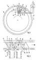
- the electric motor 2 shown in FIG. 1is an outer rotor motor, in which an essentially tubular outer rotor acts as the first functional part 4 around an inner, essentially cylindrical, second functional part 6, namely the stator of the electric motor 2 can rotate.
- the stator 6has stator poles 8 distributed in a ring shape, which - when considering a specific point in time - are progressively alternately an electromagnetic north pole or south pole in the circumferential direction.
- the poles 8are each provided with a winding 10, and the windings 10 form the conductor system of the motor 2.
- Permanent magnets 12are provided on the inside of the rotor 8, which in the section of FIG. 1 are triangular with a radially inwardly pointing tip, adjacent permanent magnets 12 abutting their edges radially on the outside. Progressing in the circumferential direction, magnetically conductive material regions 14 are provided between the permanent magnets 12, which in the section of FIG. 1 are essentially triangular with a radially outwardly pointing tip.
- the permanent magnets 12 and the material areas 14, taken together,have a circular configuration in the section of FIG. 1 and form the excitation system 16 of the motor 2.
- the permanent magnets 12 and the material areas 14are arranged in a substantially circular, single or multiple manner Surround bandage 18, which consists for example of substantially circumferential glass fibers, carbon fibers, Kevlar threads or plastic or plastic reinforced with such fibers.
- the active surfaceis not a two-dimensional surface, but an "active layer" with one not necessary maneuverably the same thickness everywhere, measured perpendicular to the relative direction of movement.
- the individual poles 8are almost the same width as the material areas 14 radially on the inside.
- the permanent magnets 12consist continuously or overall of the same material and are magnetized essentially in the circumferential direction of the rotor 4, as indicated by the arrows, so that - progressively in the circumferential direction - a permanent magnet 12 with a clockwise facing north pole on a permanent magnet 12 follows with a counterclockwise north pole, etc. Since, for each material area 14 considered, the sum of the magnetic flux cross-sectional areas of the two circumferentially adjacent permanent magnets 12 is greater than its magnetic flux exit surface 22 into the active surface 24, there is a significant overlap in the active surface 24 the remanent field strength of the permanent magnets 12 lying magnetic field strength.
- a sensor attached to the outer circumference of the stator 6which responds to the magnetic fields of the permanent magnets 12 moving past, whereby the relative position of the rotor 4 and the stator 6 is detected.
- the signals from the sensor 26are fed to a control unit 28, which reverses the polarity of a DC supply voltage for the conductor system at the point in time when, as shown in FIG. 1, the stator poles 8 are each just in the center opposite the material regions 14.
- the machineis built as a generator, no electronic control for commutation is required, but it can be present to rectify the generated electricity in the generator, so to speak.
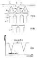
- the drawn representation of the first functional part 4 in one planecan either be understood as a development of a rotary motor according to FIG. 1 or as a representation of a linear motor 2.
- the magnetic flux lines 30 belonging to a magnetic circuit of the motor 2, consisting of a permanent magnet 12, half a material region 14 to the left, half a material region 14 to the right and two half electromagnets 8, 10are shown. Furthermore, with a permanent magnet 12, magnetic flux cross-sectional areas 21 are drawn in at two points at right angles to the active area 24. The respective cross-sectional area 21 can be thought of as a projection of the relevant connection area 20 onto the adjacent material area 14 in the direction of relative movement. The magnetic flux concentration can be seen from the magnetic flux cross-sectional areas 21 of the permanent magnets 12 in the corresponding part of the active surface 24.
- the permanent magnets on both sideseach have a nose 34 which extends in the relative movement direction 32 and with which they engage in corresponding grooves 30 in the material regions 14.
- the permanent magnets 12 and the material areas 14are pushed together perpendicular to the plane of the drawing in FIG. 2. In this way, a mutual, form-fitting anchoring of the permanent magnets 12 and the material areas 14 is created.
- the load-bearing part 18 corresponding to the bandage of FIG. 1can be less strong or unnecessary.
- the material areas 14 in the middle areaconsist of a material 36 of very high magnetic conductivity and in their left and right edge areas shown in FIG. 2 each of a material 38 with a lower magnetic conductivity.
- FIG. 3shows an embodiment in which, in deviation from the previously described embodiments, the surface of the first functional part 4 facing the second functional part 6 is designed such that the width a of the air gap is smaller in the central region of the material regions 14 than in the peripheral regions the material areas 14. This results in protrusion areas 40 which come closer to the second functional part 6 than the areas in between. This ensures that the inductance of the motor is particularly small in the position shown in FIG. 3a, which is conducive to rapid current build-up in the windings 10 after the voltage reversal by the control unit 28.
- the poles 8each have their center facing the, possibly flattened, tip of a permanent magnet 12 facing the active surface 24, the inductance of the motor is higher, which is particularly advantageous for supplying the motor with pulsed direct current .
Landscapes
- Engineering & Computer Science (AREA)
- Power Engineering (AREA)
- Permanent Field Magnets Of Synchronous Machinery (AREA)
- Reciprocating, Oscillating Or Vibrating Motors (AREA)
- Permanent Magnet Type Synchronous Machine (AREA)
- Glass Compositions (AREA)
- Eye Examination Apparatus (AREA)
- Iron Core Of Rotating Electric Machines (AREA)
- Devices For Conveying Motion By Means Of Endless Flexible Members (AREA)
- Electrical Discharge Machining, Electrochemical Machining, And Combined Machining (AREA)
- Non-Mechanical Conveyors (AREA)
Abstract
Description
Translated fromGermanDie Erfindung bezieht sich auf eine elektrische Maschine, die ein erstes Funktionsteil mit einem dauermagnetischen Erregersystem und ein zweites Funktionsteil mit einem Leitersystem aufweist, wobei das erste Funktionsteil und das zweite Funktionsteil längs einer Luftspalt-Wirkfläche relativ zueinander bewegbar sind.The invention relates to an electrical machine which has a first functional part with a permanent magnetic excitation system and a second functional part with a conductor system, the first functional part and the second functional part being movable relative to one another along an air gap active surface.
Mit dieser Aussage ist eine elektrische Maschine in breitester Form umschrieben, wobei lediglich durch die Angabe eines dauermagnetischen Erregersystems ein speziellerer Sektor aus dem Kreis der elektrischen Maschinen herausgegriffen ist. Elektrische Maschinen dieser Art findet man am häufigsten als Gleichstrommotoren, bei denen an der Wirkfläche dauermagnetische Nordpole und Südpole miteinander abwechseln und bei denen der funktionserforderliche, magnetische Rückschluß zwischen benachbarten Magnetpolen entweder durch einen Eisenrücken auf der der Wirkfläche abgewandten Rückseite der Dauermagnete erfolgt oder dadurch, daß die Dauermagnete in unterschiedlicher Richtung magnetisierte Teilbereiche eines einheitlichen magnetischen Körpers sind. Das zweite Funktionsteil weist das Leitersystem in der Regel in Form von Wicklungen oder Spulen, die einzelnen Polen zugeordnet sind, auf. Damit der Elektromotor laufen kann, muß die Stromrichtung in den einzelnen Wicklungen jeweils nach Relativbewegung der beiden Funktionsteile um eine bestimmte Strecke umgekehrt werden, was durch mechanische oder elektronische Kommutierung geschehen kann.This statement describes an electrical machine in its broadest form, with a more specific sector being selected from the circle of electrical machines simply by specifying a permanent magnetic excitation system. Electrical machines of this type are most commonly found as direct current motors, in which permanent magnetic north poles and south poles alternate with each other on the active surface and in which the functionally required, magnetic inference between adjacent magnetic poles takes place either by an iron back on the back of the permanent magnets facing away from the active surface or by the fact that the permanent magnets are magnetized partial areas of a uniform magnetic body in different directions. The conductor system usually has the second functional part in the form of windings or coils which are assigned to individual poles. So that the electric motor can run, the current direction in the individual Windings are reversed each time after a relative movement of the two functional parts, which can be done by mechanical or electronic commutation.
Der Erfindung liegt die Aufgabe zugrunde, eine elektrische Maschine der eingangs genannten Art verfügbar zu machen, die sich aufgrund ihrer Konstruktion mit höherer Drehmoment- und Leistungsdichte, bezogen auf das Gewicht oder das Volumen, bauen läßt.The invention has for its object to provide an electrical machine of the type mentioned, which can be built due to its construction with higher torque and power density, based on the weight or volume.
Zur Lösung dieser Aufgabe ist die elektrische Maschine erfindungsgemäß dadurch gekennzeichnet, daß das erste Funktionsteil - fortschreitend in Relativbewegungsrichtung betrachtet - eine wechselnde Folge von in Relativbewegungsrichtung magnetisierten Dauermagneten und magnetisch leitenden Materialbereichen aufweist, daß die magnetisch leitenden Materialbereiche jeweils - der Wirkfläche zugewandt - eine Magnetfluß-Austrittsfläche aufweisen, die kleiner als die Summe der Magnetfluß-Querschnittsflächen der beiden anschließenden Dauermagnete ist, so daß der Magnetfluß der Dauermagnete für die Wirkfläche konzentriert wird, und daß die in Relativbewegungsrichtung gemessene Breite bei den Dauermagneten mit zunehmendem Abstand von der Wirkfläche zunimmt und bei den magnetisch leitenden Bereichen mit zunehmendem Abstand von der Wirkfläche abnimmt.To achieve this object, the electrical machine according to the invention is characterized in that the first functional part - viewed progressively in the direction of relative movement - has an alternating sequence of permanent magnets magnetized in the direction of relative movement and magnetically conductive material areas, that the magnetically conductive material areas each - facing the active surface - have a magnetic flux Have exit surface that is smaller than the sum of the magnetic flux cross-sectional areas of the two subsequent permanent magnets, so that the magnetic flux of the permanent magnets is concentrated for the active surface, and that the width measured in the direction of relative movement increases with increasing distance from the active surface and with the magnetically conductive areas decreases with increasing distance from the active surface.
Bei bisherigen elektrischen Maschinen ist die magnetische Feldstärke der Dauermagnete des Erregersystems durch das verwendete Dauermagnetmaterial nach oben begrenzt und ist hierdurch eine obere Grenze für die Magnetflußdichte über die Wirkfläche gegeben. Wenn man nach Aus schöpfung dieser Parameter das Drehmoment einer herkömmlichen elektrischen Maschine erhöhen will, muß man die Wirkfläche vergrößern. Dies läuft bei einer rotierenden elektrischen Maschine auf einen größeren Durchmesser oder eine größere axiale Länge hinaus.In previous electrical machines, the magnetic field strength of the permanent magnets of the excitation system has an upper limit due to the permanent magnet material used and there is thus an upper limit for the magnetic flux density over the active surface. If you go to Aus creation of these parameters to increase the torque of a conventional electrical machine, one must increase the effective area. In the case of a rotating electrical machine, this amounts to a larger diameter or a greater axial length.
Durch die Erfindung wird ein grundlegend andersartiger Weg eröffnet, indem über die Wirkfläche vom ersten Funktionsteil zum zweiten Funktionsteil führend eine Luftspaltfeldsärke erreicht wird, die wesentlich über der Remanenzfeldstärke der verwendeten Dauermagnete liegt. Der "Übersetzungsfaktor" des B-Felds ist im wesentlichen durch das Verhältnis der Größe der Magnetfluß-Querschnittsfläche eines Dauermagneten zur halben Magnetfluß-Austrittsfläche in die Wirkfläche des auf einer Seite an den Dauermagneten anschließenden, magnetisch leitenden Materialbereichs bestimmt. Der Übersetzungsfaktor kann problemlos größer als 1,2 oder größer als 1,3 oder größer als 1,5, ja sogar größer als 2,0 sein.The invention opens up a fundamentally different way in that an air gap field strength is achieved leading from the first functional part to the second functional part, which is substantially above the remanent field strength of the permanent magnets used. The "translation factor" of the B field is essentially determined by the ratio of the size of the magnetic flux cross-sectional area of a permanent magnet to half the magnetic flux exit area into the effective area of the magnetically conductive material region adjoining the permanent magnet on one side. The translation factor can easily be greater than 1.2 or greater than 1.3 or greater than 1.5, even greater than 2.0.
Wenn das B-Feld im Luftspalt größer ist, wird im Falle gleicher Maschinengröße die Windungszahl bei den Polen des Leitersystems erniedrigt. Aus der kleineren Windungszahl resultiert eine quadratisch niedrigere Induktivität im zweiten Funktionsteil. Dies bedeutet, daß bei unveränderter Drehzahl in der Maschine ein höherer Strom gewendet werden kann bzw. derselbe Strom bei höherer Drehzahl gewendet werden kann, wodurch die Leistung der Maschine entsprechend ansteigt.If the B field in the air gap is larger, the number of turns at the poles of the conductor system is reduced if the machine size is the same. The smaller number of turns results in a quadratic lower inductance in the second functional part. This means that if the speed of the machine remains unchanged, a higher current can be turned or the same current can be turned at a higher speed, which increases the performance of the machine accordingly.
Im anderen Falle ergibt sich die Möglichkeit, die Maschine - im Fall der rotierenden Maschine - beispielsweise axial kürzer zu bauen oder - im Fall der Linear maschine - quer zur Relativbewegungsrichtung schmaler zu bauen, ohne die im zweiten Funktionsteil induzierte EMK zu verkleinern und ohne die Induktivität zu verändern, so daß der Elektromotor weiterhin gleiche Leistung abgibt. Die geschilderten Umstände wirken dahingehend zusammen, daß man aufgrund der Erfindung bei gleichem Volumen oder Gewicht eine elektrische Maschine mit höherem Drehmoment oder höherer Leistung bzw. - im Fall des elektrischen Generators - mit höherer elektrischer Leistung bauen kann. Oder anders ausgedrückt: bei geforderter Leistung kann die Maschine kleiner und leichter sein.In the other case, there is the possibility of building the machine - in the case of the rotating machine - for example axially shorter or - in the case of the linear machine - to build narrower transversely to the relative movement direction without reducing the EMF induced in the second functional part and without changing the inductance, so that the electric motor continues to deliver the same power. The described circumstances work together in such a way that an electric machine with higher torque or higher power or - in the case of the electrical generator - with higher electrical power can be built on the basis of the invention with the same volume or weight. In other words, the machine can be smaller and lighter when performance is required.
Da die in Relativbewegungsrichtung gemessene Breite bei den Dauermagneten mit zunehmendem Abstand von der Wirkfläche zunimmt, und da diese Breite bei den magnetisch leitenden Bereichen mit zunehmendem Abstand von der Wirkfläche abnimmt, ergeben sich eine konstruktiv günstige Konfiguration, kleine Reluktanzeffekte und hohe Materialausnutzung.Since the width measured in the direction of relative movement increases with increasing distance from the active surface with the permanent magnets, and since this width decreases with increasing distance from the active surface with the magnetically conductive areas, a structurally favorable configuration, small reluctance effects and high material utilization result.
Bei der erfindungsgemäßen elektrischen Maschine kann es sich um einen Elektromotor oder um einen Stromgenerator handeln. Eine an sich als Elektromotor vorgesehene Maschine kann auch im Generatorbetrieb betrieben werden. Es kann sich um eine linear arbeitende oder eine rotierend arbeitende elektrische Maschine handeln, wobei im erstgenannten Fall die Wirkfläche eine Ebene mit endlicher Breite und mehr oder weniger großer Länge ist und wobei im zweitgenannten Fall die Wirkfläche entweder zylindrisch ist, wenn sich das erste und das zweite Funktionsteil radial gegenüberliegen, oder kreisringförmig ist, wenn sich das erste und das zweite Funktionsteil axial gegenüberliegen. Somit ist die Relativbewegungs richtung entweder geradlinig oder kreisförmig.The electrical machine according to the invention can be an electric motor or a current generator. A machine provided as an electric motor can also be operated in generator mode. It can be a linearly working or a rotatingly working electrical machine, in the former case the active surface is a plane with finite width and more or less great length, and in the second case the active surface is either cylindrical if the first and that the second functional part is radially opposite, or is annular if the first and the second functional part are axially opposite. So the relative movement direction either straight or circular.
Die zur Wirkfläche gerichteten Magnetfluß-Austrittsflächen der magnetisch leitenden Materialbereiche sind in der Regel im Fall der Linearmaschine und im Fall der rotierenden Maschine mit axial beabstandetem ersten und zweitem Funktionsteil eben, und im Fall der rotierenden Maschine mit radial beabstandetem ersten und zweitem Funktionsteil zylindrisch, müssen es aber nicht sein. Wenn die Magnetfluß-Austrittsflächen von diesen einfachen Geometrien abweichen, ist sinnvollerweise jeweils die Projektion der betreffenden Fläche auf die entsprechende Vergleichsfläche der geschilderten einfachen Geometrie zu betrachten, um das im Anspruch 1 angesprochene Flächenverhältnis zu bestimmen. In der Regel sind die Dauermagnete des Erregersystems - fortschreitend in Relativbewegungsrichtung betrachtet - wechselnd gepolt, so daß auf den Südpol eines ersten Dauermagneten der Südpol eines zweiten Dauermagneten, auf den Nordpol des zweiten Dauermagneten den Nordpol eines dritten eines Dauermagneten, und auf den Südpol des dritten Dauermagneten der Südpol eines vierten Dauermagneten folgt, usw. Es sind jedoch Konfigurationen denkbar, bei denen keine derart strenge, wechselnde Folge der Magnetisierungsrichtung der Dauermagnete gegeben ist. Außerdem wird darauf hingewiesen, daß auch erfindungsgemäße elektrische Maschinen denkbar sind, bei denen zwischen den Dauermagneten kein magnetisch leitendes Material angeordnet ist, sondern Luft.The magnetic flux exit surfaces of the magnetically conductive material areas directed towards the active surface are generally flat in the case of the linear machine and in the case of the rotating machine with axially spaced first and second functional parts, and cylindrical in the case of the rotating machine with radially spaced first and second functional parts but it shouldn't be. If the magnetic flux exit surfaces deviate from these simple geometries, it is sensible to consider the projection of the surface in question onto the corresponding comparison surface of the simple geometry described in order to determine the area ratio mentioned in claim 1. As a rule, the permanent magnets of the excitation system - viewed progressively in the direction of relative movement - are alternately polarized, so that on the south pole of a first permanent magnet the south pole of a second permanent magnet, on the north pole of the second permanent magnet the north pole of a third of a permanent magnet, and on the south pole of the third Permanent magnets follow the south pole of a fourth permanent magnet, etc. However, configurations are conceivable in which there is no such strict, changing sequence of the magnetization direction of the permanent magnets. In addition, it is pointed out that electrical machines according to the invention are also conceivable in which no magnetically conductive material is arranged between the permanent magnets, but air.
Nach einer bevorzugten Weiterbildung der Erfindung reicht die dem zweiten Funktionsteil zugewandte Fläche des ersten Funktionsteils - fortschreitend in Relativbewegungsrichtung betrachtet - wechselnd mehr oder weniger nah an das zweite Funktionsteil heran. Mit dieser Maßnahme läßt sich erreichen, daß bei bestimmten Relativstellungen von erstem und zweitem Funktionsteil der Magnetfluß pro einzelnem magnetischen Kreis der Maschine maximal und bei anderen Relativstellungen kleiner als maximal ist. Bei kleinerem elektrisch induziertem Magnetfluß ist die Induktivität der Maschine zu dem entsprechenden Zeitpunkt kleiner, was zu denjenigen Zeiten günstig ist, zu denen die Stromrichtung im Leitersystem des zweiten Funktionsteils umgedreht wird. Wenn der elektrisch induzierte Magnetfluß maximal ist, ist zu dem entsprechenden Zeitpunkt bzw. in der entsprechenden Zeitspanne die Induktivität der Maschine maximal, was während derjenigen Zeitspanne günstig ist, in der dem Leitersystem Strom gleicher Richtung zugeführt wird. Dies gilt ganz besonders für Ausführungsformen der Maschine, bei denen in den Zeitspannen zwischen der Stromumkehr im Leitersystem dem Leitersystem Strom nicht zeitlich konstant zugeführt wird, sondern gepulst. Besonders günstig erreicht man die vorstehend abgehandelten Effekte, wenn die magnetisch leitfähigen Bereiche auf der der Wirkfläche zugewandten Seite jeweils in ihrem Mittelbereich näher an das zweite Funktionteil heranreichen, also dort die Weite des Luftspalts verkleinert ist. Oder anders ausgedrückt: Die magnetisch leitfähigen Bereiche sind auf der der Wirkfläche zugewandten Seite an ihren den beiden benachbarten Dauermagneten zugewandten Rändern derart ausgenommen, daß dort die Weite des Luftspalts größer ist.According to a preferred development of the invention, the surface of the first functional part facing the second functional part - viewed progressively in the direction of relative movement - alternately reaches more or less close to the second functional part. With this measure it can be achieved that with certain relative positions of the first and second functional part the magnetic flux per individual magnetic circuit of the machine is maximal and with other relative positions smaller than maximal. With a smaller electrically induced magnetic flux, the inductance of the machine is smaller at the corresponding point in time, which is favorable at those times when the current direction in the conductor system of the second functional part is reversed. If the electrically induced magnetic flux is at a maximum, the inductance of the machine is at a maximum at the corresponding point in time or in the corresponding period, which is favorable during the period in which current of the same direction is supplied to the conductor system. This applies in particular to embodiments of the machine in which current is not supplied to the conductor system in a constant manner over time, but rather in a pulsed manner in the periods between the current reversal in the conductor system. The effects dealt with above are achieved particularly favorably if the magnetically conductive regions on the side facing the active surface each come closer to the second functional part in their central region, that is to say the width of the air gap is reduced there. In other words, the magnetically conductive areas on the side facing the active surface are excluded at their edges facing the two adjacent permanent magnets in such a way that the width of the air gap is greater there.
Ähnliche Effekte kann man erzeugen, indem die magnetisch leitfähigen Bereiche - fortschreitend in Relativbewegungsrichtung betrachtet - aus Materialien unterschiedlicher magnetischer Leitfähigkeit zusammengesetzt sind. Konkret könnte man im mittleren Bereich jedes leitfähigen Materialbereichs ein Material hoher magnetischer Leitfähigkeit und in den beiden Randbereichen des magnetisch leitfähigen Materialbereichs ein Material niedrigerer magnetischer Leitfähigkeit vorsehen.Similar effects can be created if the magnetically conductive areas - progressively viewed in the direction of relative movement - are composed of materials of different magnetic conductivity. Specifically, one could provide a material of high magnetic conductivity in the central region of each conductive material region and a material of lower magnetic conductivity in the two edge regions of the magnetically conductive material region.
Günstigerweise können die Dauermagnete jeweils durchgehend aus dem gleichen Material bestehen, sind also vorzugsweise weder in Relativbewegungsrichtung noch quer zur Relativbewegungsrichtung schichtweise aus unterschiedlichen Materialien aufgebaut.Conveniently, the permanent magnets can consist of the same material throughout, that is, they are preferably built up layer by layer from different materials neither in the relative movement direction nor transversely to the relative movement direction.
Vorzugsweise bestehen die Dauermagnete aus einem Material mit einer Permeabilität nahe der Permeabilität von Luft, so daß µr nahe Eins ist. Besonders bevorzugte Materialien sind Materialien auf der Basis von Se-Co (Se = seltene Erden, insbesondere Samarium), Fe-Nd und bestimmte Ferrite. Dies verringert die Induktivität der Magnetkreise der Maschine.The permanent magnets preferably consist of a material with a permeability close to the permeability of air, so that µr is close to one. Particularly preferred materials are materials based on Se-Co (Se = rare earths, especially samarium), Fe-Nd and certain ferrites. This reduces the inductance of the machine's magnetic circuits.
Vorzugsweise ist die erfindungsgemäße Maschine ein elektronisch kommutiert. Derartige Maschinen zeichnen sich insbesondere durch optimale Regelbarkeit und Verschleißfreiheit aus. Gespeist werden kann ein derartiger Elektromotor im einfachsten Fall mit Gleichstrom, wobei vorzugsweise in den Zeitspannen zwischen der Stromwendung bzw. der Umkehr der Stromrichtung im Leitersystem des zweiten Funktionsteils eine Gleichspannung angelegt wird, die durch die elektroni sche Kommutierungseinrichtung zur Einhaltung einer gewünschten regelbaren, mittleren Stromhöhe zu und weggeschaltet bzw. getaktet wird. Eine günstige niedrige Taktfrequenz ergibt sich bei der weiter vorn geschilderten hohen Induktivität der Maschine in den Zeitspannen zwischen der Stromwendung. Wenn zur Speisung eine Wechselstromquelle zur Verfügung steht, kann der Elektromotor aus einem Gleichspannungszwischenkreis gespeist werden.The machine according to the invention is preferably an electronically commutated one. Such machines are characterized in particular by optimal controllability and freedom from wear. In the simplest case, such an electric motor can be fed with direct current, a direct voltage being preferably applied in the time periods between the reversal of current or the reversal of the current direction in the conductor system of the second functional part, which is caused by the electronics cal commutation device to maintain a desired controllable, average current level and is switched or clocked. A favorable low clock frequency results from the high inductance of the machine described above in the time periods between the current reversal. If an alternating current source is available for the supply, the electric motor can be supplied from a direct voltage intermediate circuit.
Die erfindungsgemäße elektrische Maschine kann entweder ein relativ zu dem stationären zweiten Funktionsteil bewegbares erstes Funktionsteil, oder ein relativ zu dem stationären ersten Funktionsteil bewegbares zweites Funktionsteil, oder auch zwei relativ zueinander bewegbare Funktionsteile, von denen keines stationär ist, aufweisen. Besonders bevorzugt ist jedoch, wenn das erste Funktionsteil der bewegbare Teil der elektrischen Maschine ist, insbesondere weil dem ersten Funktionsteil kein Strom zugeführt werden muß.The electrical machine according to the invention can either have a first functional part that can be moved relative to the stationary second functional part, or a second functional part that can be moved relative to the stationary first functional part, or also two functional parts that can be moved relative to one another, none of which is stationary. However, it is particularly preferred if the first functional part is the movable part of the electrical machine, in particular because no current has to be supplied to the first functional part.
Wenn die erfindungsgemäße elektrische Maschine als rotierende Maschine mit zylindrischer Wirkfläche gebaut ist, kommen prinzipiell die beiden Möglichkeiten Außenrotor und Innenrotor in Betracht. Die Außenrotorbauweise ist im Interesse eines möglichst großen Durchmessers der Wirkfläche und damit möglichst großen Drehmoments bei gegebenem Volumen bevorzugt, weil der Erregerteil in der Regel radial weniger Raum beansprucht als das Leitersystem des zweiten Funktionsteils.If the electrical machine according to the invention is constructed as a rotating machine with a cylindrical active surface, the two options outer rotor and inner rotor come into consideration in principle. The outer rotor design is preferred in the interest of the largest possible diameter of the active surface and thus the greatest possible torque for a given volume, because the excitation part generally takes up less radial space than the conductor system of the second functional part.
Da die erfindungsgemäße elektrische Maschine ohne magnetischen Rückschluß auf der der Wirkfläche abgewandten Rückseite des Erregersystems auskommt, ist es bevorzugt, die Dauermagnete und die magnetisch leitfähigen Bereiche formschlüssig miteinander zu verbinden und/oder auf der der Wirkfläche abgewandten Rückseite des Erregersystems ein Lastaufnahmeteil aus magnetisch nicht leitfähigem Material vorzusehen. Das Lastaufnahmeteil ist im Fall rotierender Maschinen mit zylindrischer Wirkfläche im wesentlichen zylindrisch, im Fall rotierender Maschinen mit kreisringförmiger Wirkfläche im wesentlichen kreisförmig oder kreisringförmig, und im Fall einer linearen Maschine im wesentlichen rechteckig. Das Lastaufnahmeteil läßt sich besonders günstig aus Kunststoff, insbesondere faserverstärktem Kunststoff, fertigen. Im Fall einer rotierenden Maschine mit Außenrotor ist es besonders günstig, in dem Lastaufnahmeteil eine ringförmige Bandage vorzusehen oder das Lastaufnahmeteil insgesamt als ringförmige Bandage auszubilden, die die Bauteile des Erregersystems gegen die Zentrifugalkraft zusammenhält. Lastaufnahmeteile können mit modernen Werkstoffen, insbesondere Faserwerkstoffen oder faserverstärkten Kunststoff-Werkstoffen, mit extrem hoher mechanischer Festigkeit bei geringem Volumen und geringem Gewicht gebaut werden.Since the electrical machine according to the invention manages without magnetic inference on the back of the excitation system facing away from the active surface, it is preferred to connect the permanent magnets and the magnetically conductive areas in a form-fitting manner and / or on the back of the excitation system facing away from the active surface, a load-bearing part made of magnetically non-conductive To provide material. The load-bearing part is essentially cylindrical in the case of rotating machines with a cylindrical active surface, essentially circular or annular in the case of rotating machines with a circular active surface, and essentially rectangular in the case of a linear machine. The load-bearing part can be manufactured particularly cheaply from plastic, in particular fiber-reinforced plastic. In the case of a rotating machine with an external rotor, it is particularly advantageous to provide an annular bandage in the load-bearing part or to design the load-bearing part overall as an annular bandage which holds the components of the excitation system together against the centrifugal force. Load suspension parts can be built with modern materials, in particular fiber materials or fiber-reinforced plastic materials, with extremely high mechanical strength with a small volume and low weight.
Es wird darauf hingewiesen, daß die in den abhängigen Ansprüchen angegebenen Merkmale mindestens teilweise auch technisch sinnvoll verwirklichbar sind, wenn nicht zugleich sämtliche Merkmale mindestens des Anspruchs 1 vorhanden sind. Dies gilt ganz besonders für die Merkmale der Ansprüche 3, 5 und 12, für die auch ohne Einbeziehung aller Merkmale des Anspruchs 1 erfinderischer Charakter beansprucht wird.It is pointed out that the features specified in the dependent claims can at least partially also be implemented in a technically meaningful manner if not all of the features of claim 1 are present at the same time. This is particularly true for the features of
Die Erfindung und Weiterbildungen der Erfindung werden im folgenden anhand von zeichnerisch dargestellten Ausführungsbeispielen noch näher erläutert. Es zeigen:
- Fig. 1 schematisch eine elektrische Maschine mit Rotationsbewegung in einem Schnitt rechtwinklig zur Rotationsachse, wobei Teile weggelassen sind;
- Fig. 2 einen Teil einer elektrischen Maschine mit Linearbewegung oder Rotationsbewegung, in einem Schnitt rechtwinklig zur Wirkfläche der Maschine und enthaltend die Relativbewegungsrichtung;
- Fig. 3 eine im Vergleich zu Fig. 2 abgewandelte, elektrische Maschine in gleicher Schnittdarstellung;
- Fig. 4 eine graphische Darstellung der Änderung der Induktivität der Maschine gemäß Fig. 3 bei sich ändernder Relativstellung von erstem und zweitem Funktionsteil.
- Figure 1 shows schematically an electrical machine with rotational movement in a section perpendicular to the axis of rotation, parts being omitted.
- 2 shows a part of an electrical machine with linear movement or rotational movement, in a section perpendicular to the active surface of the machine and containing the relative movement direction;
- 3 shows an electrical machine modified in comparison to FIG. 2 in the same sectional view;
- Fig. 4 is a graphical representation of the change in the inductance of the machine according to Fig. 3 with changing relative position of the first and second functional part.
Die in Fig. 1 bis 3 schematisch dargestellten Maschinen können entweder ein Stromgenerator oder ein Elektromotor sein. Die folgende Beschreibung orientiert sich in erster Linie an dem Fall des Elektromotors, wobei jedoch aufgrunddessen das Verständnis eines entsprechend aufgebauten Generators für den Durchschnittsfachmann auf der Hand liegt.The machines shown schematically in FIGS. 1 to 3 can either be a current generator or an electric motor. The following description is primarily based on the case of the electric motor, but because of this the understanding of a correspondingly constructed generator is obvious to the average person skilled in the art.
Der in Fig. 1 dargestellte Elektromotor 2 ist ein Außenrotormotor, bei dem sich ein im wesentlichen rohrförmiger Außenrotor als erstes Funktionsteil 4 um ein inneres, im wesentlichen zylindrisches, zweites Funktionsteil 6, nämlich den Stator des Elektromotors 2, drehen kann. Der Stator 6 weist ringförmig verteilt Statorpole 8 auf, die - bei Betrachtung eines bestimmten Zeitpunkts - in Umfangsrichtung fortschreitend abwechselnd ein elektromagnetischer Nordpol oder Südpol sind. Die Pole 8 sind jeweils mit einer Wicklung 10 versehen, und die Wicklungen 10 bilden das Leitersystem des Motors 2.The
Am Rotor 8 sind innenseitig Dauermagnete 12 vorgesehen, die im Schnitt der Fig. 1 dreieckig mit radial nach innen weisender Spitze sind, wobei benachbarte Dauermagnete 12 radial außen mit ihren Rändern aneinanderstoßen. In Umfangsrichtung fortschreitend sind zwischen den Dauermagneten 12 jeweils magnetisch leitende Materialbereiche 14 vorgesehen, die im Schnitt der Fig. 1 im wesentlichen dreieckig mit radial nach außen weisender Spitze sind. Die Dauermagnete 12 und die Materialbereiche 14 haben, zusammen betrachtet, im Schnitt der Fig. 1 eine kreisringförmige Konfiguration und bilden das Erregersystem 16 des Motors 2. Radial außen sind die Dauermagnete 12 und die Materialbereiche 14 durch eine im wesentlichen kreisförmige, einfach oder mehrfach herumgelegte Bandage 18 umgeben, die beispielsweise aus im wesentlichen in Umfangsrichtung verlaufenden Glasfasern, Carbonfasern, Kevlar-Fäden oder Kunststoff oder mit derartigen Fasern verstärktem Kunststoff besteht.
Zwischen dem Innenumfang des Rotors 4 und dem Außenumfang des Stators 6 befindet sich eine im wesentlichen zylindrische Wirkfläche mit einer radialen Weite a, die üblicherweise als Luftspaltweite bezeichnet wird. Die Wirkfläche ist strenggenommen keine zweidimensionale Fläche, sondern eine "Wirkschicht" mit einer nicht not wendigerweise überall gleichen Dicke, gemessen senkrecht zur Relativbewegungsrichtung.Between the inner circumference of the rotor 4 and the outer circumference of the
In Umfangsrichtung gemessen sind die einzelnen Pole 8 nahezu gleich breit wie die Materialbereiche 14 radial innen.Measured in the circumferential direction, the
Die Dauermagnete 12 bestehen jeweils durchgehend bzw. insgesamt aus dem gleichen Material und sind im wesentlichen in Umfangsrichtung des Rotors 4 magnetisiert, wie durch die eingezeichneten Pfeile angedeutet, so daß - in Umfangsrichtung fortschreitend - auf einen Dauermagneten 12 mit im Uhrzeigersinn weisendem Nordpol ein Dauermagnet 12 mit entgegen dem Uhrzeigersinn weisenden Nordpol folgt usw. Da bei jedem betrachteten Materialbereich 14 die Summe der Magnetfluß-Querschnittsflächen der beiden, in Umfangsrichtung benachbarten Dauermagneten 12 größer ist als seine Magnetfluß-Austrittsfläche 22 in die Wirkfläche 24, herrscht in der Wirkfläche 24 eine erheblich über der Remanenzfeldstärke der Dauermagnete 12 liegende magnetische Feldstärke.The
Mit 26 ist ein am Außenumfang des Stators 6 befestigter Sensor bezeichnet, der auf die Magnetfelder der vorbeibewegten Dauermagnete 12 anspricht, wodurch die Relativstellung von Rotor 4 und Stator 6 erfaßt wird. Die Signale des Sensors 26 werden einer Steuereinheit 28 zugeführt, die eine Speisungsgleichspannung für das Leitersystem zu demjenigen Zeitpunkt umpolt, wenn sich, wie in Fig. 1 gezeichnet, die Statorpole 8 jeweils gerade mittig gegenüber den Materialbereichen 14 befinden. Alternativ kann man einen zusammen mit dem Rotor 4 rotierenden Ring mit Steuerungs-Dauermagneten vorsehen, auf die der Sensor 26 anspricht.With a sensor attached to the outer circumference of the
Wenn die Maschine als Generator gebaut ist, ist keine elektronische Steuerung zur Kommutierung erforderlich, kann aber vorhanden sein, um den erzeugten Strom sozusagen im Generator gleichzurichten.If the machine is built as a generator, no electronic control for commutation is required, but it can be present to rectify the generated electricity in the generator, so to speak.
In den Fig. 2 und 3 sind die geschilderten, grundsätzlichen Verhältnisse nochmals in größerem Maßstab dargestellt und sind weitere zusätzliche, bevorzugte Einzelheiten veranschaulicht. Die gezeichnete Darstellung des ersten Funktionsteils 4 in einer Ebene kann man entweder als Abwicklung eines Rotationsmotors gemäß Fig. 1 oder alsDarstellung eines linearen Motors 2 verstehen.2 and 3, the described, fundamental relationships are shown again on a larger scale and further additional, preferred details are illustrated. The drawn representation of the first functional part 4 in one plane can either be understood as a development of a rotary motor according to FIG. 1 or as a representation of a
Es sind die zu einem magnetischen Kreis des Motors 2, bestehend aus einem Dauermagneten 12, einem halben Materialbereich 14 links davon, einem halben Materialbereich 14 rechts davon und zwei halben Elektromagneten 8, 10, gehörenden Magnetflußlinien 30 eingezeichnet. Ferner sind bei einem Dauermagneten 12 an zwei Stellen Magnetfluß-Querschnittsflächen 21 rechtwinklig zur Wirkfläche 24 eingezeichnet. Die jeweilige Querschnittsfläche 21 kann man sich als Projektion der betreffenden Anschlußfläche 20 an den angrenzenden Materialbereich 14 in Relativbewegungsrichtung vorstellen. Man erkennt die Magnetflußkonzentration von den Magnetfluß-Querschnittsflächen 21 der Dauermagnete 12 in den entsprechenden Teil der Wirkfläche 24.The
Außerdem erkennt man, daß die Dauermagnete beidseits jeweils eine sich in Relativbewegungsrichtung 32 erstreckende Nase 34 aufweisen, mit denen sie in entsprechende Nuten 30 der Materialbereiche 14 greifen. Zur Montage werden die Dauermagnete 12 und die Materialbereiche 14 senkrecht zur Zeichenebene der Fig. 2 zusammengeschoben. Auf diese Weise entsteht eine gegenseitige, formschlüssige Verankerung der Dauermagnete 12 und der Materialbereiche 14. Insbesondere bei weniger hoch belasteten Motoren kann dadurch das der Bandage von Fig. 1 entsprechende Lastaufnahmeteil 18 weniger stark oder entbehrlich sein.It can also be seen that the permanent magnets on both sides each have a
Ferner ist die Möglichkeit eingezeichnet, daß die Materialbereiche 14 im mittleren Bereich aus einem Material 36 sehr hoher magnetischer Leitfähigkeit bestehen und in ihren, in Fig. 2 eingezeichneten linken und rechten Randbereichen jeweils aus einem Material 38 mit geringerer magnetischen Leitfähigkeit.Furthermore, the possibility is shown that the
In Fig. 3 ist eine Ausführungsform dargestellt, bei der abweichend von den bisher beschriebenen Ausführungsformen die dem zweiten Funktionsteil 6 zugewandte Fläche des ersten Funktionsteils 4 so gestaltet ist, daß die Weite a des Luftspalts jeweils im mittleren Bereich der Materialbereiche 14 kleiner als in den Randbereichen der Materialbereiche 14 ist. Es ergeben sich somit Vorsprungsbereiche 40, die näher an das zweite Funktionsteil 6 heranreichen als die Bereiche dazwischen. Hierdurch wird erreicht, daß in der in Fig. 3a gezeichneten Stellung die Induktivität des Motors besonders klein ist, was einem raschen Stromaufbau in den Wicklungen 10 nach der Spannungsumkehrung durch die Steuereinheit 28 förderlich ist.3 shows an embodiment in which, in deviation from the previously described embodiments, the surface of the first functional part 4 facing the second
Wenn hingegen, wie in Fig. 3b gezeichnet, die Pole 8 jeweils mit ihrer Mitte der der Wirkfläche 24 zugewandten, ggf. abgeflachten Spitze eines Dauermagneten 12 gegenüberliegen ist die Induktivität des Motors höher, was insbesondere für die Versorgung des Motors mit gepulstem Gleichstrom günstiger ist. Diese Verhältnisse sind in Fig. 4 graphisch veranschaulicht.If, on the other hand, as shown in FIG. 3b, the
Claims (14)
Translated fromGermandadurch gekennzeichnet,
daß das erste Funktionsteil (4) - fortschreitend in Relativbewegungsrichtung (32) betrachtet - eine wechselnde Folge von in Relativbewegungsrichtung (32) magnetisierten Dauermagneten (12) und magnetisch leitenden Materialbereichen (14) aufweist; daß die magnetisch leitenden Materialbereiche (14) jeweils - der Wirkfläche (24) zugewandt - eine Magnetfluß-Austrittsfläche (22) aufweisen, die kleiner als die Summe der Magnetfluß-Querschnittsflächen (21) der beiden anschließenden Dauermagnete (12) ist, so daß der Magnetfluß der Dauermagnete (12) für die Wirkfläche (24) konzentriert wird; und
daß die in Relativbewegungsrichtung (32) gemessene Breite bei den Dauermagneten (12) mit zunehmendem Abstand von der Wirkfläche (24) zunimmt und bei den magnetisch leitenden Bereichen (14) mit zunehmendem Abstand von der Wirkfläche (24) abnimmt.1. Electrical machine (2) having a first functional part (4) with a permanent magnetic excitation system (12) and a second functional part (6) with a conductor system (10), the first functional part (4) and the second functional part (6 ) are movable relative to each other along an air gap effective surface (24),
characterized,
that the first functional part (4) - progressively in Relative movement direction (32) considered - has an alternating sequence of permanent magnets (12) magnetized in the relative movement direction (32) and magnetically conductive material regions (14); that the magnetically conductive material areas (14) each - facing the active surface (24) - have a magnetic flux exit surface (22) which is smaller than the sum of the magnetic flux cross-sectional areas (21) of the two subsequent permanent magnets (12), so that the Magnetic flux of the permanent magnets (12) for the active surface (24) is concentrated; and
that the width measured in the relative movement direction (32) increases for the permanent magnets (12) with increasing distance from the active surface (24) and decreases for magnetically conductive areas (14) with increasing distance from the active surface (24).
dadurch gekennzeichnet,
daß die Dauermagnete (12) und die magnetisch leitenden Bereiche (14) im Schnitt im wesentlichen dreieckig sind.2. Electrical machine according to claim 1,
characterized,
that the permanent magnets (12) and the magnetically conductive areas (14) are essentially triangular in section.
dadurch gekennzeichnet,
daß die dem zweiten Funktionsteil (6) zugewandte Fläche des ersten Funktionsteils (4) - fortschreitend in Relativbewegungsrichtung (32) betrachtet - wechselnd mehr oder weniger nah an das zweite Funktionsteil (6) heranreicht.3. Electrical machine according to claim 1 or 2,
characterized,
that the surface of the first functional part (4) facing the second functional part (6) - progressively viewed in the relative movement direction (32) - alternately reaches more or less close to the second functional part (6).
dadurch gekennzeichnet,
daß die magnetisch leitfähigen Bereiche (14) jeweils in der Mitte einen näher an das zweite Funktionsteil (6) heranreichenden Vorsprung (40) haben.4. Electrical machine according to claim 3,
characterized,
that the magnetically conductive areas (14) each in the middle have a projection (40) that comes closer to the second functional part (6).
dadurch gekennzeichnet,
daß die magnetisch leitfähigen Bereiche (14) - fortschreitend in Relativbewegungsrichtung (32) betrachtet - aus Materialien unterschiedlicher magnetischer Leitfähigkeit zusammengesetzt sind.5. Electrical machine according to one of claims 1 to 4,
characterized,
that the magnetically conductive areas (14) - progressively viewed in the relative movement direction (32) - are composed of materials of different magnetic conductivity.
dadurch gekennzeichnet,
daß die Dauermagnete (12) jeweils durchgehend aus dem gleichen Material bestehen.6. Electrical machine according to one of claims 1 to 5,
characterized,
that the permanent magnets (12) consist of the same material throughout.
dadurch gekennzeichnet,
daß die Dauermagnete (12) aus einem Material mit einer Permeabilität nahe der Permeabilität von Luft bestehen.7. Electrical machine according to one of claims 1 to 6,
characterized,
that the permanent magnets (12) consist of a material with a permeability close to the permeability of air.
dadurch gekennzeichnet,
daß sie elektronisch kommutiert ist.8. Electrical machine according to one of claims 1 to 7,
characterized,
that it is commutated electronically.
dadurch gekennzeichnet,
daß das erste Funktionsteil (4) der bewegbare Teil der elektrischen Maschine ist.9. Electrical machine according to one of claims 1 to 8,
characterized,
that the first functional part (4) is the movable part of the electrical machine.
dadurch gekennzeichnet,
daß sie als rotierende Maschine mit Außenrotor gebaut ist.10. Electrical machine according to claim 9,
characterized,
that it is built as a rotating machine with an external rotor.
dadurch gekennzeichnet,
daß die Dauermagnete (12) und die magnetisch leitfähigen Bereiche (14) formschlüssig miteinander verbunden sind.11. Electrical machine according to one of claims 1 to 10,
characterized,
that the permanent magnets (12) and the magnetically conductive areas (14) are positively connected to one another.
dadurch gekennzeichnet,
daß an der der Wirkfläche (24) abgewandten Rückseite der Dauermagnete (12) und der magnetisch leitfähigen Bereiche (14) ein Lastaufnahmeteil (18) aus magnetisch nicht leitfähigem Material vorgesehen ist.12. Electrical machine according to one of claims 1 to 11,
characterized,
that a load-bearing part (18) made of magnetically non-conductive material is provided on the back of the permanent magnets (12) and the magnetically conductive areas (14) facing away from the active surface (24).
dadurch gekennzeichnet,
daß das Lastaufnahmeteil (18) aus, vorzugsweise faserverstärktem, Kunststoff gefertigt ist.13. Electrical machine according to claim 12,
characterized,
that the load-bearing part (18) is made of, preferably fiber-reinforced, plastic.
dadurch gekennzeichnet,
daß das Lastaufnahmeteil (18) eine außen um einen Außenrotor herumgelegte Bandage aufweist.14. Electrical machine according to claim 12 or 13,
characterized,
that the load-bearing part (18) has a bandage wrapped around the outside of an outer rotor.
Applications Claiming Priority (2)
| Application Number | Priority Date | Filing Date | Title |
|---|---|---|---|
| DE3806760 | 1988-03-02 | ||
| DE3806760ADE3806760A1 (en) | 1988-03-02 | 1988-03-02 | ELECTRIC MACHINE |
Publications (2)
| Publication Number | Publication Date |
|---|---|
| EP0331180A1true EP0331180A1 (en) | 1989-09-06 |
| EP0331180B1 EP0331180B1 (en) | 1996-02-07 |
Family
ID=6348634
Family Applications (1)
| Application Number | Title | Priority Date | Filing Date |
|---|---|---|---|
| EP89103691AExpired - LifetimeEP0331180B1 (en) | 1988-03-02 | 1989-03-02 | Electric machine |
Country Status (12)
| Country | Link |
|---|---|
| US (1) | US5128575A (en) |
| EP (1) | EP0331180B1 (en) |
| JP (1) | JP2799209B2 (en) |
| AT (1) | ATE134083T1 (en) |
| AU (1) | AU616745B2 (en) |
| BR (1) | BR8907292A (en) |
| DE (2) | DE3806760A1 (en) |
| DK (1) | DK173945B1 (en) |
| ES (1) | ES2086307T3 (en) |
| NO (1) | NO180509C (en) |
| RU (1) | RU2141716C1 (en) |
| WO (1) | WO1989008346A1 (en) |
Cited By (12)
| Publication number | Priority date | Publication date | Assignee | Title |
|---|---|---|---|---|
| WO1991005398A1 (en)* | 1989-09-28 | 1991-04-18 | Magnet-Motor Gesellschaft Für Magnetmotorische Technik Mbh | Electrical machine with fluid cooling |
| FR2728115A1 (en)* | 1994-12-02 | 1996-06-14 | Fichtel & Sachs Ag | ROTOR FOR AN ELECTRIC MACHINE, AND MANUFACTURING METHOD THEREOF |
| DE19503610A1 (en)* | 1995-02-03 | 1996-08-14 | Zajc Franc | Electrical machine stator and rotor design for multi-phase electrical machine |
| US5578879A (en)* | 1989-09-28 | 1996-11-26 | Heidelberg; G+E,Uml O+Ee Tz | Electric machine with fluid cooling |
| EP0784008A2 (en) | 1996-01-10 | 1997-07-16 | Magnet-Motor Gesellschaft für magnetmotorische Technik mbH | Vehicle propelled by muscle-power |
| US5744888A (en)* | 1995-02-03 | 1998-04-28 | Tiedtke-Buhling-Kinne & Partner | Multiphase and multipole electrical machine |
| WO1999010962A1 (en)* | 1997-08-27 | 1999-03-04 | Magnet-Motor Gesellschaft Für Magnetmotorische Technik Mbh | Electric machine with a rotor constructed of permanent magnets and magnetic flux guides |
| DE102004031329A1 (en)* | 2004-06-29 | 2006-01-19 | Klinger, Friedrich, Prof. Dr. Ing. | External rotor for a generator in a wind power installation has an outer ring (OR) and a grouping with a permanent magnet of components following each other at a tangent on the OR inner side |
| US7658251B2 (en) | 2006-09-20 | 2010-02-09 | James Harry K | Direct drive electric traction motor |
| CN103378664A (en)* | 2012-04-17 | 2013-10-30 | 西门子公司 | Pole shoe arrangement for a machine element of an electrical machine |
| EP3057191A1 (en)* | 2015-02-13 | 2016-08-17 | Enrichment Technology Company Ltd. Zweigniederlassung Deutschland | Outer rotor permanent magnet motor |
| EP2346149A4 (en)* | 2008-11-05 | 2017-08-09 | Mitsubishi Heavy Industries, Ltd. | Linear actuator |
Families Citing this family (32)
| Publication number | Priority date | Publication date | Assignee | Title |
|---|---|---|---|---|
| US5280209A (en)* | 1989-11-14 | 1994-01-18 | The United States Of America As Represented By The Secretary Of The Army | Permanent magnet structure for use in electric machinery |
| DE4128627C2 (en)* | 1991-08-26 | 1994-06-23 | Mannesmann Ag | Method for changing the speed of a vehicle and vehicle for performing this method |
| JP2695332B2 (en)* | 1991-11-26 | 1997-12-24 | 三菱電機株式会社 | Permanent magnet field type rotor |
| WO2004075379A1 (en)* | 1992-03-18 | 2004-09-02 | Kazuto Sakai | Axial gap rotaitng electric machine |
| DE4426241C2 (en)* | 1994-07-23 | 1997-07-17 | Fichtel & Sachs Ag | Electric machine with a rotor |
| DE19633209A1 (en)* | 1995-08-28 | 1997-03-06 | Papst Motoren Gmbh & Co Kg | Reducing reluctance moment or cogging of electric motor |
| US6800977B1 (en)* | 1997-12-23 | 2004-10-05 | Ford Global Technologies, Llc. | Field control in permanent magnet machine |
| DE19835575A1 (en) | 1998-08-06 | 2000-03-02 | Mannesmann Sachs Ag | Parallel hybrid drive for a motor vehicle with a clutch integrated in the electrical machine and associated electric motor assembly |
| DE10010248A1 (en)* | 2000-03-02 | 2001-09-13 | Hatz Motoren | Current generator unit for vehicle, has rotor built on fan wheel attached by flange to crankshaft of drive engine and stator designed as laminated iron packet |
| DE10043120A1 (en)* | 2000-08-31 | 2002-04-11 | Wolfgang Hill | Electrical machine for high magnetic reversal frequencies |
| US6787951B2 (en)* | 2001-10-01 | 2004-09-07 | Wavecrest Laboratories, Llc | Rotary electric motor having controller and power supply integrated therein |
| DE10224776A1 (en)* | 2002-06-04 | 2004-03-11 | Magnet-Motor Gesellschaft Für Magnetmotorische Technik Mbh | Electrical machine |
| DE10360713A1 (en)* | 2003-12-19 | 2005-07-28 | Institut für Automatisierung und Informatik GmbH Zentrum für industrielle Forschung und Entwicklung Wernigerode | Electromagnetic actuator e.g. for combustion engine valves, has flux-concentrating elements bordering on permanent magnets |
| RU2267856C1 (en)* | 2004-04-29 | 2006-01-10 | Общество с ограниченной ответственностью научно-производственная фирма "Особые сварочные агрегаты" (ООО НПФ "ОСА") | Synchronous generator plant with excitation from permanent magnets |
| RU2273942C1 (en)* | 2004-07-27 | 2006-04-10 | Общество с ограниченной ответственностью научно-производственная фирма "Особые сварочные агрегаты" (ООО НПФ "ОСА") | Synchronous generator with excitation by permanent magnets |
| US20070063595A1 (en)* | 2005-03-23 | 2007-03-22 | Farhad Habibi | Electric machine and method of manufacture |
| CN1734881A (en)* | 2005-06-29 | 2006-02-15 | 陆孝庭 | Brushless rotary motor |
| RU2305359C2 (en)* | 2005-08-05 | 2007-08-27 | Общество с ограниченной ответственностью научно-производственная фирма "Особые сварочные агрегаты" (ООО НПФ "ОСА") | Permanent-magnet excited synchronous generator, primarily used as welding generator |
| JP4719023B2 (en)* | 2006-02-10 | 2011-07-06 | 矢崎総業株式会社 | Meter |
| EA200800674A1 (en)* | 2008-01-24 | 2008-10-30 | Открытое Акционерное Общество "Инжиниринговая Нефтегазовая Компания - Всероссийский Научно-Исследовательский Институт По Строительству И Эксплуатации Трубопроводов, Объектов Тэк" | MULTI-PHASE ELECTRIC MACHINE WITH PERMANENT MAGNETS |
| JP2009240047A (en) | 2008-03-26 | 2009-10-15 | Panasonic Electric Works Co Ltd | Drive method of electromagnetic actuator |
| US7965010B2 (en)* | 2008-09-03 | 2011-06-21 | Bose Corporation | Linear motor with patterned magnet arrays |
| US20100060004A1 (en)* | 2008-09-05 | 2010-03-11 | Young Ho Ro | Frictionless Generator |
| JP5515478B2 (en)* | 2009-07-17 | 2014-06-11 | 株式会社安川電機 | Periodic magnetic field generator and linear motor and rotary motor using the same |
| JP5015316B2 (en)* | 2010-12-28 | 2012-08-29 | 株式会社安川電機 | Reluctance motor |
| RU2467454C1 (en)* | 2011-05-25 | 2012-11-20 | Федеральное государственное бюджетное образовательное учреждение высшего профессионального образования "Санкт-Петербургский государственный политехнический университет" (ФГОУ ВПО "СПбГПУ") | Inverted valve motor |
| US20140125438A1 (en)* | 2011-06-30 | 2014-05-08 | Nathan Senthilvel Ambalam | Excited ferro electro dynamo |
| JP5752177B2 (en)* | 2013-05-09 | 2015-07-22 | 三菱電機株式会社 | Magnet rotating machine |
| RU2548662C1 (en)* | 2014-06-05 | 2015-04-20 | Федеральное государственное бюджетное образовательное учреждение высшего профессионального образования "Уфимский государственный авиационный технический университет" | Synchronous generator with excitation from permanent magnets |
| US11139707B2 (en) | 2015-08-11 | 2021-10-05 | Genesis Robotics And Motion Technologies Canada, Ulc | Axial gap electric machine with permanent magnets arranged between posts |
| KR20180093872A (en) | 2015-08-11 | 2018-08-22 | 제네시스 로보틱스 엘엘피 | Electric machine |
| US11043885B2 (en) | 2016-07-15 | 2021-06-22 | Genesis Robotics And Motion Technologies Canada, Ulc | Rotary actuator |
Citations (4)
| Publication number | Priority date | Publication date | Assignee | Title |
|---|---|---|---|---|
| FR2473803A1 (en)* | 1980-01-10 | 1981-07-17 | Jeumont Schneider | Small motor permanent magnet rotor - has alternately stacked discs of trapezoidal cross-section magnetic material and permanent magnet discs(BR 27.7.81) |
| US4336649A (en)* | 1978-12-26 | 1982-06-29 | The Garrett Corporation | Method of making rotor assembly having anchor with undulating sides |
| US4645961A (en)* | 1983-04-05 | 1987-02-24 | The Charles Stark Draper Laboratory, Inc. | Dynamoelectric machine having a large magnetic gap and flexible printed circuit phase winding |
| FR2606951A1 (en)* | 1986-11-13 | 1988-05-20 | Alsthom Cgee | Motor with magnets |
Family Cites Families (18)
| Publication number | Priority date | Publication date | Assignee | Title |
|---|---|---|---|---|
| DE1848663U (en)* | 1960-09-14 | 1962-03-22 | Deutsche Edelstahlwerke Ag | POLE WHEEL EQUIPPED WITH PERMANENT MAGNETS. |
| DE1848662U (en)* | 1961-03-01 | 1962-03-22 | Deutsche Edelstahlwerke Ag | STATOR EQUIPPED WITH PERMANENT MAGNETS FOR ELECTRIC MACHINES. |
| US3581394A (en)* | 1969-05-13 | 1971-06-01 | Russell E Phelon | Rotor annulus for electric generator |
| US3836801A (en)* | 1973-03-07 | 1974-09-17 | Hitachi Ltd | Stator for dc machines |
| US3950662A (en)* | 1974-06-04 | 1976-04-13 | Photocircuits Division Of Kollmorgen Corporation | Self-commutating motor and printed circuit armature therefor |
| SU560292A1 (en)* | 1976-05-14 | 1977-05-30 | Челябинский Политехнический Институт Им.Ленинского Комсомола | Electric machine inductor |
| FR2356301A1 (en)* | 1976-06-21 | 1978-01-20 | Kumakura Shokichi | ANNULAR MAGNETIC ASSEMBLY FOR DYNAMO-ELECTRIC GENERATOR |
| CA1103298A (en)* | 1977-02-25 | 1981-06-16 | Masami Uchiyama | Electric motor with discrete rotor position and speed sensors |
| JPS589500Y2 (en)* | 1977-06-24 | 1983-02-21 | 株式会社デンソー | magnet generator rotor |
| US4339874A (en)* | 1978-12-26 | 1982-07-20 | The Garrett Corporation | Method of making a wedge-shaped permanent magnet rotor assembly |
| JPS58163255A (en)* | 1982-03-24 | 1983-09-28 | Okuma Mach Works Ltd | Rotor for permanent magnet type synchronous motor |
| US4787902A (en)* | 1982-04-01 | 1988-11-29 | Sheets John H | Multi-positionable intraocular lens |
| JPS5959057A (en)* | 1982-09-27 | 1984-04-04 | Fanuc Ltd | Rotor for synchronous machine |
| BG39783A1 (en)* | 1984-05-08 | 1986-08-15 | Popov | Rotor with permanent magnets for electric machine |
| GB2172443A (en)* | 1985-03-13 | 1986-09-17 | Dowty Fuel Syst Ltd | Electrical machines |
| US4930201A (en)* | 1985-08-14 | 1990-06-05 | Kollmorgen Corporation | Method for manufacturing a composite sleeve for an electric motor |
| JPH0759138B2 (en)* | 1986-03-14 | 1995-06-21 | 工業技術院長 | Synchronous motor rotor |
| SU1436209A1 (en)* | 1987-04-13 | 1988-11-07 | Предприятие П/Я Г-4514 | Electric machine |
- 1988
- 1988-03-02DEDE3806760Apatent/DE3806760A1/ennot_activeWithdrawn
- 1989
- 1989-03-02JPJP1503415Apatent/JP2799209B2/ennot_activeExpired - Fee Related
- 1989-03-02ESES89103691Tpatent/ES2086307T3/ennot_activeExpired - Lifetime
- 1989-03-02DEDE58909593Tpatent/DE58909593D1/ennot_activeExpired - Fee Related
- 1989-03-02USUS07/573,043patent/US5128575A/ennot_activeExpired - Lifetime
- 1989-03-02BRBR898907292Apatent/BR8907292A/ennot_activeIP Right Cessation
- 1989-03-02WOPCT/EP1989/000208patent/WO1989008346A1/enunknown
- 1989-03-02ATAT89103691Tpatent/ATE134083T1/ennot_activeIP Right Cessation
- 1989-03-02RUSU4831043Apatent/RU2141716C1/ennot_activeIP Right Cessation
- 1989-03-02EPEP89103691Apatent/EP0331180B1/ennot_activeExpired - Lifetime
- 1989-03-02AUAU32992/89Apatent/AU616745B2/ennot_activeCeased
- 1990
- 1990-08-27NONO903746Apatent/NO180509C/enunknown
- 1990-08-30DKDK199002081Apatent/DK173945B1/ennot_activeIP Right Cessation
Patent Citations (4)
| Publication number | Priority date | Publication date | Assignee | Title |
|---|---|---|---|---|
| US4336649A (en)* | 1978-12-26 | 1982-06-29 | The Garrett Corporation | Method of making rotor assembly having anchor with undulating sides |
| FR2473803A1 (en)* | 1980-01-10 | 1981-07-17 | Jeumont Schneider | Small motor permanent magnet rotor - has alternately stacked discs of trapezoidal cross-section magnetic material and permanent magnet discs(BR 27.7.81) |
| US4645961A (en)* | 1983-04-05 | 1987-02-24 | The Charles Stark Draper Laboratory, Inc. | Dynamoelectric machine having a large magnetic gap and flexible printed circuit phase winding |
| FR2606951A1 (en)* | 1986-11-13 | 1988-05-20 | Alsthom Cgee | Motor with magnets |
Non-Patent Citations (1)
| Title |
|---|
| PATENT ABSTRACTS OF JAPAN vol. 8, no. 161 (E-257) 1598 26 Juli 1984, & JP-A-59 59057 (FANUC)* |
Cited By (16)
| Publication number | Priority date | Publication date | Assignee | Title |
|---|---|---|---|---|
| WO1991005398A1 (en)* | 1989-09-28 | 1991-04-18 | Magnet-Motor Gesellschaft Für Magnetmotorische Technik Mbh | Electrical machine with fluid cooling |
| US5578879A (en)* | 1989-09-28 | 1996-11-26 | Heidelberg; G+E,Uml O+Ee Tz | Electric machine with fluid cooling |
| FR2728115A1 (en)* | 1994-12-02 | 1996-06-14 | Fichtel & Sachs Ag | ROTOR FOR AN ELECTRIC MACHINE, AND MANUFACTURING METHOD THEREOF |
| DE19503610A1 (en)* | 1995-02-03 | 1996-08-14 | Zajc Franc | Electrical machine stator and rotor design for multi-phase electrical machine |
| US5744888A (en)* | 1995-02-03 | 1998-04-28 | Tiedtke-Buhling-Kinne & Partner | Multiphase and multipole electrical machine |
| EP0784008A2 (en) | 1996-01-10 | 1997-07-16 | Magnet-Motor Gesellschaft für magnetmotorische Technik mbH | Vehicle propelled by muscle-power |
| DE19600698A1 (en)* | 1996-01-10 | 1997-08-07 | Magnet Motor Gmbh | Vehicle that can be operated with muscle power, especially a bicycle |
| US6384504B1 (en) | 1997-08-27 | 2002-05-07 | Magnet-Motor Gesellschaft Für Magnetmotorische Technik Mbh | Electric machine with a rotor constructed of permanent magnets and magnetic flux guides |
| WO1999010962A1 (en)* | 1997-08-27 | 1999-03-04 | Magnet-Motor Gesellschaft Für Magnetmotorische Technik Mbh | Electric machine with a rotor constructed of permanent magnets and magnetic flux guides |
| DE102004031329A1 (en)* | 2004-06-29 | 2006-01-19 | Klinger, Friedrich, Prof. Dr. Ing. | External rotor for a generator in a wind power installation has an outer ring (OR) and a grouping with a permanent magnet of components following each other at a tangent on the OR inner side |
| US7658251B2 (en) | 2006-09-20 | 2010-02-09 | James Harry K | Direct drive electric traction motor |
| EP2346149A4 (en)* | 2008-11-05 | 2017-08-09 | Mitsubishi Heavy Industries, Ltd. | Linear actuator |
| CN103378664A (en)* | 2012-04-17 | 2013-10-30 | 西门子公司 | Pole shoe arrangement for a machine element of an electrical machine |
| CN103378664B (en)* | 2012-04-17 | 2017-08-25 | 西门子公司 | Pole shoe structure for the machine parts of motor |
| EP3057191A1 (en)* | 2015-02-13 | 2016-08-17 | Enrichment Technology Company Ltd. Zweigniederlassung Deutschland | Outer rotor permanent magnet motor |
| WO2016128262A1 (en)* | 2015-02-13 | 2016-08-18 | Enrichment Technology Company Ltd. Zweigniederlassung Deutschland | External-rotor permanent-magnet motor |
Also Published As
| Publication number | Publication date |
|---|---|
| JPH03503114A (en) | 1991-07-11 |
| RU2141716C1 (en) | 1999-11-20 |
| US5128575A (en) | 1992-07-07 |
| NO903746D0 (en) | 1990-08-27 |
| NO180509B (en) | 1997-01-20 |
| NO180509C (en) | 1997-04-30 |
| DK208190A (en) | 1990-08-30 |
| AU3299289A (en) | 1989-09-22 |
| ATE134083T1 (en) | 1996-02-15 |
| EP0331180B1 (en) | 1996-02-07 |
| DE58909593D1 (en) | 1996-03-21 |
| ES2086307T3 (en) | 1996-07-01 |
| NO903746L (en) | 1990-08-27 |
| DK173945B1 (en) | 2002-03-04 |
| BR8907292A (en) | 1991-03-12 |
| JP2799209B2 (en) | 1998-09-17 |
| DE3806760A1 (en) | 1989-09-14 |
| WO1989008346A1 (en) | 1989-09-08 |
| DK208190D0 (en) | 1990-08-30 |
| AU616745B2 (en) | 1991-11-07 |
Similar Documents
| Publication | Publication Date | Title |
|---|---|---|
| EP0331180B1 (en) | Electric machine | |
| DE68914841T2 (en) | ELECTRIC MOTOR. | |
| DE2843384C2 (en) | Electric machine | |
| DE19512419B4 (en) | Permanent magnet electric machine | |
| EP1110298A1 (en) | Electrical machine with permanent magnets | |
| EP3545610A1 (en) | Synchronous machine having magnetic rotary field reduction and flux concentration | |
| DE8306650U1 (en) | Brushless DC motor | |
| DE1538834A1 (en) | Stepper motor | |
| DE3122049A1 (en) | DC external-rotor motor having no commutator | |
| DE102014214469B4 (en) | rotor for an electric machine | |
| DE69921211T2 (en) | Electric machine with double excitation, and in particular vehicle generator | |
| WO1998059407A1 (en) | Electric drive mechanism with a magnetic bearing | |
| DE1918500A1 (en) | Impulse operated electric actuator | |
| DE3933790C2 (en) | Electrical machine with a rotor and a stator | |
| EP0094978A1 (en) | Rotatable electrical machine | |
| DE3006354C2 (en) | Asynchronous cylindrical linear motor | |
| EP2104976B1 (en) | Electrical machine | |
| EP4111579A1 (en) | Electric motor | |
| DE3433695C1 (en) | Electronically commutated DC machine and its use | |
| EP0500873B1 (en) | Electrical machine | |
| DE2913691C2 (en) | Stand for a brushless electric motor | |
| DE68911905T2 (en) | Electric motor without power converter parts with poles set up in the direction of the axis and magnetic motor based on the same principle. | |
| DE9200116U1 (en) | Electric machine | |
| EP0483778B1 (en) | Rotating electric motor | |
| DE4213372A1 (en) | Permanent-magnet electric machine with rounded ends of stator teeth - spreads magnetic flux at leading and trailing ends flanking gaps between adjacent pole pieces close to rotating radial magnets |
Legal Events
| Date | Code | Title | Description |
|---|---|---|---|
| PUAI | Public reference made under article 153(3) epc to a published international application that has entered the european phase | Free format text:ORIGINAL CODE: 0009012 | |
| AK | Designated contracting states | Kind code of ref document:A1 Designated state(s):AT BE CH DE ES FR GB GR IT LI LU NL SE | |
| 17P | Request for examination filed | Effective date:19900301 | |
| 17Q | First examination report despatched | Effective date:19911227 | |
| GRAA | (expected) grant | Free format text:ORIGINAL CODE: 0009210 | |
| AK | Designated contracting states | Kind code of ref document:B1 Designated state(s):AT BE CH DE ES FR GB GR IT LI LU NL SE | |
| PG25 | Lapsed in a contracting state [announced via postgrant information from national office to epo] | Ref country code:GR Free format text:LAPSE BECAUSE OF FAILURE TO SUBMIT A TRANSLATION OF THE DESCRIPTION OR TO PAY THE FEE WITHIN THE PRESCRIBED TIME-LIMIT Effective date:19960207 | |
| REF | Corresponds to: | Ref document number:134083 Country of ref document:AT Date of ref document:19960215 Kind code of ref document:T | |
| REF | Corresponds to: | Ref document number:58909593 Country of ref document:DE Date of ref document:19960321 | |
| PG25 | Lapsed in a contracting state [announced via postgrant information from national office to epo] | Ref country code:LU Free format text:LAPSE BECAUSE OF NON-PAYMENT OF DUE FEES Effective date:19960331 | |
| ITF | It: translation for a ep patent filed | ||
| ET | Fr: translation filed | ||
| GBT | Gb: translation of ep patent filed (gb section 77(6)(a)/1977) | Effective date:19960509 | |
| REG | Reference to a national code | Ref country code:ES Ref legal event code:FG2A Ref document number:2086307 Country of ref document:ES Kind code of ref document:T3 | |
| REG | Reference to a national code | Ref country code:CH Ref legal event code:NV Representative=s name:BUECHEL, VON REVY & PARTNER | |
| PLBE | No opposition filed within time limit | Free format text:ORIGINAL CODE: 0009261 | |
| STAA | Information on the status of an ep patent application or granted ep patent | Free format text:STATUS: NO OPPOSITION FILED WITHIN TIME LIMIT | |
| 26N | No opposition filed | ||
| REG | Reference to a national code | Ref country code:GB Ref legal event code:IF02 | |
| PGFP | Annual fee paid to national office [announced via postgrant information from national office to epo] | Ref country code:BE Payment date:20060323 Year of fee payment:18 | |
| PGFP | Annual fee paid to national office [announced via postgrant information from national office to epo] | Ref country code:AT Payment date:20060324 Year of fee payment:18 | |
| PGFP | Annual fee paid to national office [announced via postgrant information from national office to epo] | Ref country code:IT Payment date:20060331 Year of fee payment:18 | |
| PGFP | Annual fee paid to national office [announced via postgrant information from national office to epo] | Ref country code:NL Payment date:20070319 Year of fee payment:19 | |
| PGFP | Annual fee paid to national office [announced via postgrant information from national office to epo] | Ref country code:GB Payment date:20070323 Year of fee payment:19 Ref country code:ES Payment date:20070323 Year of fee payment:19 | |
| PGFP | Annual fee paid to national office [announced via postgrant information from national office to epo] | Ref country code:SE Payment date:20070326 Year of fee payment:19 | |
| PGFP | Annual fee paid to national office [announced via postgrant information from national office to epo] | Ref country code:CH Payment date:20070329 Year of fee payment:19 | |
| PGFP | Annual fee paid to national office [announced via postgrant information from national office to epo] | Ref country code:DE Payment date:20070522 Year of fee payment:19 | |
| PG25 | Lapsed in a contracting state [announced via postgrant information from national office to epo] | Ref country code:AT Free format text:LAPSE BECAUSE OF NON-PAYMENT OF DUE FEES Effective date:20070302 | |
| BERE | Be: lapsed | Owner name:*HEIDELBERG MOTOR G.- FUER ENERGIEKONVERTER M.B.H. Effective date:20070331 | |
| PG25 | Lapsed in a contracting state [announced via postgrant information from national office to epo] | Ref country code:BE Free format text:LAPSE BECAUSE OF NON-PAYMENT OF DUE FEES Effective date:20070331 | |
| PGFP | Annual fee paid to national office [announced via postgrant information from national office to epo] | Ref country code:FR Payment date:20070321 Year of fee payment:19 | |
| REG | Reference to a national code | Ref country code:CH Ref legal event code:PL | |
| EUG | Se: european patent has lapsed | ||
| GBPC | Gb: european patent ceased through non-payment of renewal fee | Effective date:20080302 | |
| PG25 | Lapsed in a contracting state [announced via postgrant information from national office to epo] | Ref country code:NL Free format text:LAPSE BECAUSE OF NON-PAYMENT OF DUE FEES Effective date:20081001 | |
| NLV4 | Nl: lapsed or anulled due to non-payment of the annual fee | Effective date:20081001 | |
| REG | Reference to a national code | Ref country code:FR Ref legal event code:ST Effective date:20081125 | |
| PG25 | Lapsed in a contracting state [announced via postgrant information from national office to epo] | Ref country code:CH Free format text:LAPSE BECAUSE OF NON-PAYMENT OF DUE FEES Effective date:20080331 Ref country code:SE Free format text:LAPSE BECAUSE OF NON-PAYMENT OF DUE FEES Effective date:20080303 Ref country code:LI Free format text:LAPSE BECAUSE OF NON-PAYMENT OF DUE FEES Effective date:20080331 Ref country code:DE Free format text:LAPSE BECAUSE OF NON-PAYMENT OF DUE FEES Effective date:20081001 | |
| PG25 | Lapsed in a contracting state [announced via postgrant information from national office to epo] | Ref country code:FR Free format text:LAPSE BECAUSE OF NON-PAYMENT OF DUE FEES Effective date:20080331 | |
| REG | Reference to a national code | Ref country code:ES Ref legal event code:FD2A Effective date:20080303 | |
| PG25 | Lapsed in a contracting state [announced via postgrant information from national office to epo] | Ref country code:GB Free format text:LAPSE BECAUSE OF NON-PAYMENT OF DUE FEES Effective date:20080302 | |
| PG25 | Lapsed in a contracting state [announced via postgrant information from national office to epo] | Ref country code:ES Free format text:LAPSE BECAUSE OF NON-PAYMENT OF DUE FEES Effective date:20080303 | |
| PG25 | Lapsed in a contracting state [announced via postgrant information from national office to epo] | Ref country code:IT Free format text:LAPSE BECAUSE OF NON-PAYMENT OF DUE FEES Effective date:20070302 |