EP0329002B1 - Reclinable wheelchair - Google Patents
Reclinable wheelchairDownload PDFInfo
- Publication number
- EP0329002B1 EP0329002B1EP89102151AEP89102151AEP0329002B1EP 0329002 B1EP0329002 B1EP 0329002B1EP 89102151 AEP89102151 AEP 89102151AEP 89102151 AEP89102151 AEP 89102151AEP 0329002 B1EP0329002 B1EP 0329002B1
- Authority
- EP
- European Patent Office
- Prior art keywords
- seat
- section
- backrest
- brace
- base section
- Prior art date
- Legal status (The legal status is an assumption and is not a legal conclusion. Google has not performed a legal analysis and makes no representation as to the accuracy of the status listed.)
- Expired - Lifetime
Links
- 239000004606Fillers/ExtendersSubstances0.000claimsdescription14
- 230000007246mechanismEffects0.000claimsdescription7
- 125000006850spacer groupChemical group0.000claimsdescription5
- 230000000712assemblyEffects0.000claimsdescription4
- 238000000429assemblyMethods0.000claimsdescription4
- 238000006073displacement reactionMethods0.000claimsdescription4
- 230000001105regulatory effectEffects0.000claimsdescription4
- 241000826860TrapeziumSpecies0.000claimsdescription2
- 230000000153supplemental effectEffects0.000description5
- XAGFODPZIPBFFR-UHFFFAOYSA-NaluminiumChemical compound[Al]XAGFODPZIPBFFR-UHFFFAOYSA-N0.000description2
- 229910052782aluminiumInorganic materials0.000description2
- 238000010276constructionMethods0.000description2
- 230000009977dual effectEffects0.000description2
- 210000001503jointAnatomy0.000description2
- 210000001364upper extremityAnatomy0.000description2
- 229910001069Ti alloyInorganic materials0.000description1
- 239000002131composite materialSubstances0.000description1
- 230000000694effectsEffects0.000description1
- 230000005057finger movementEffects0.000description1
- 230000005484gravityEffects0.000description1
- 230000000717retained effectEffects0.000description1
Images


Classifications
- A—HUMAN NECESSITIES
- A61—MEDICAL OR VETERINARY SCIENCE; HYGIENE
- A61G—TRANSPORT, PERSONAL CONVEYANCES, OR ACCOMMODATION SPECIALLY ADAPTED FOR PATIENTS OR DISABLED PERSONS; OPERATING TABLES OR CHAIRS; CHAIRS FOR DENTISTRY; FUNERAL DEVICES
- A61G5/00—Chairs or personal conveyances specially adapted for patients or disabled persons, e.g. wheelchairs
- A61G5/08—Chairs or personal conveyances specially adapted for patients or disabled persons, e.g. wheelchairs foldable
- A—HUMAN NECESSITIES
- A61—MEDICAL OR VETERINARY SCIENCE; HYGIENE
- A61G—TRANSPORT, PERSONAL CONVEYANCES, OR ACCOMMODATION SPECIALLY ADAPTED FOR PATIENTS OR DISABLED PERSONS; OPERATING TABLES OR CHAIRS; CHAIRS FOR DENTISTRY; FUNERAL DEVICES
- A61G5/00—Chairs or personal conveyances specially adapted for patients or disabled persons, e.g. wheelchairs
- A61G5/08—Chairs or personal conveyances specially adapted for patients or disabled persons, e.g. wheelchairs foldable
- A61G5/0808—Chairs or personal conveyances specially adapted for patients or disabled persons, e.g. wheelchairs foldable characterised by a particular folding direction
- A61G5/0816—Chairs or personal conveyances specially adapted for patients or disabled persons, e.g. wheelchairs foldable characterised by a particular folding direction folding side to side, e.g. reducing or expanding the overall width of the wheelchair
- A—HUMAN NECESSITIES
- A61—MEDICAL OR VETERINARY SCIENCE; HYGIENE
- A61G—TRANSPORT, PERSONAL CONVEYANCES, OR ACCOMMODATION SPECIALLY ADAPTED FOR PATIENTS OR DISABLED PERSONS; OPERATING TABLES OR CHAIRS; CHAIRS FOR DENTISTRY; FUNERAL DEVICES
- A61G5/00—Chairs or personal conveyances specially adapted for patients or disabled persons, e.g. wheelchairs
- A61G5/10—Parts, details or accessories
- A61G5/1056—Arrangements for adjusting the seat
- A61G5/1059—Arrangements for adjusting the seat adjusting the height of the seat
- A—HUMAN NECESSITIES
- A61—MEDICAL OR VETERINARY SCIENCE; HYGIENE
- A61G—TRANSPORT, PERSONAL CONVEYANCES, OR ACCOMMODATION SPECIALLY ADAPTED FOR PATIENTS OR DISABLED PERSONS; OPERATING TABLES OR CHAIRS; CHAIRS FOR DENTISTRY; FUNERAL DEVICES
- A61G5/00—Chairs or personal conveyances specially adapted for patients or disabled persons, e.g. wheelchairs
- A61G5/10—Parts, details or accessories
- A61G5/1056—Arrangements for adjusting the seat
- A61G5/1062—Arrangements for adjusting the seat adjusting the width of the seat
- A—HUMAN NECESSITIES
- A61—MEDICAL OR VETERINARY SCIENCE; HYGIENE
- A61G—TRANSPORT, PERSONAL CONVEYANCES, OR ACCOMMODATION SPECIALLY ADAPTED FOR PATIENTS OR DISABLED PERSONS; OPERATING TABLES OR CHAIRS; CHAIRS FOR DENTISTRY; FUNERAL DEVICES
- A61G5/00—Chairs or personal conveyances specially adapted for patients or disabled persons, e.g. wheelchairs
- A61G5/10—Parts, details or accessories
- A61G5/1056—Arrangements for adjusting the seat
- A61G5/1075—Arrangements for adjusting the seat tilting the whole seat backwards
- A—HUMAN NECESSITIES
- A61—MEDICAL OR VETERINARY SCIENCE; HYGIENE
- A61G—TRANSPORT, PERSONAL CONVEYANCES, OR ACCOMMODATION SPECIALLY ADAPTED FOR PATIENTS OR DISABLED PERSONS; OPERATING TABLES OR CHAIRS; CHAIRS FOR DENTISTRY; FUNERAL DEVICES
- A61G5/00—Chairs or personal conveyances specially adapted for patients or disabled persons, e.g. wheelchairs
- A61G5/10—Parts, details or accessories
- A61G5/12—Rests specially adapted therefor, e.g. for the head or the feet
- A61G5/128—Rests specially adapted therefor, e.g. for the head or the feet for feet
- A—HUMAN NECESSITIES
- A61—MEDICAL OR VETERINARY SCIENCE; HYGIENE
- A61G—TRANSPORT, PERSONAL CONVEYANCES, OR ACCOMMODATION SPECIALLY ADAPTED FOR PATIENTS OR DISABLED PERSONS; OPERATING TABLES OR CHAIRS; CHAIRS FOR DENTISTRY; FUNERAL DEVICES
- A61G5/00—Chairs or personal conveyances specially adapted for patients or disabled persons, e.g. wheelchairs
- A61G5/006—Chairs or personal conveyances specially adapted for patients or disabled persons, e.g. wheelchairs convertible to stretchers or beds
- A—HUMAN NECESSITIES
- A61—MEDICAL OR VETERINARY SCIENCE; HYGIENE
- A61G—TRANSPORT, PERSONAL CONVEYANCES, OR ACCOMMODATION SPECIALLY ADAPTED FOR PATIENTS OR DISABLED PERSONS; OPERATING TABLES OR CHAIRS; CHAIRS FOR DENTISTRY; FUNERAL DEVICES
- A61G5/00—Chairs or personal conveyances specially adapted for patients or disabled persons, e.g. wheelchairs
- A61G5/10—Parts, details or accessories
- A61G5/1056—Arrangements for adjusting the seat
- A61G5/107—Arrangements for adjusting the seat positioning the whole seat forward or rearward
Definitions
- the present inventionrelates to adjustable wheelchairs and, more particularly, to wheelchairs having an angularly adjustable backrest and seat.
- Reclinable wheelchairshave evolved in accordance with special needs of patients as well as improving comfort and convenience of use.
- Exemplary prior art mechanisms for tilting backrestsare shown in U.S. Patent No. 3,815,586.
- pivot barsextend from opposing armrests into the side edges of the backrest.
- a multi-orificed side plateallows for repositioning of the pivot bars and adjustment of the backrest tilt angle.
- the wheelchair seatis pivoted at its back edge and the front edge may be adjustably lifted with a toothed rack and pin device.
- Patent Applications 2136742, 2158350 and 2171898provide wheelchair mechanisms whereby reclining the backrest causes a corresponding forward movement of the seat. This maintains a lowered center of gravity for the wheelchair occupant and a more stable wheelchair disposition. However, it is unnecessary to always combine seat movement with backrest tilting. Particularly with severely handicapped patients, it is better to have the backrest separately adjustable. Such also lessens the bulk and complexity of the wheelchair mechanisms and greatly facilitates collapsibility.
- French Patent No. 2 399 822provides a wheelchair mechanism whereby a seat portion and a base portion can be collapsed relative to one another for easy transportation.
- a pair of supporting bracesare articulated at each end to the base and seat.
- the two bracesUpon collapsing the wheelchair, the two braces, being parallel, maintain the seat substantially parallel with the base such that, when collapsed, the base and seat are adjacent one another and, again, substantially parallel to each other.
- This arrangementprovides four axes of rotation of the seat section relative to the base section, but is an inflexible arrangement, in that the seat is not angularly adjustable relative to the base section.
- no meansare provided in the French patent for regulating the angular displacement of the seat section relative to the base section. On the contrary, this would be quite impossible, because of the fixed relationship between the parallel supporting braces.
- the present inventionprovides a wheelchair having an adjustable seat which simultaneously moves forward and tilts upwardly.
- the wheelchairfurther includes a backrest which is adjustable relative to the seat and is also tiltable. Both the adjustment and tilting actions are independent of seat movement.
- the present inventionprovides a wheelchair having a seat, backrest and wheels which are supported by two opposing structurally independent lateral sideframe structures, each sideframe structure comprising: a base section; a seat section spaced-apart and movable on four axes of rotation relative to said base section; brace means pivotally connecting each of said seat section and said base section, said brace means comprising a first brace member interconnecting said base section with said seat section and a second brace member interconnecting said base section with said seat section, each of said brace members having opposing ends provided with joint means for forming respective pivot connections with said base section and said seat section; and characterized by said first brace member interconnecting a back portion of said base section with said seat section, and said second brace member interconnecting a forward portion of said base section with said seat section so as to form a trapezium mechanism, whereby said seat section being angularly movable on said four axes of rotation relative to said base section; and a seat extender means inter
- a backrest extender meansmay be used to interconnect and control the inclination of backrest bars relative to the seat section.
- Remote actuating meansallows for convenient operation of both extender means.
- a front leg sectionis also pivoted to the seat section. This section is used to support a leg carrier and/or foot rest means. Angular adjustment is accomplished with an adjustable strut means.
- the base, front and seat sections and the backrest barsinclude track means with slide fasteners. These components permit a wide variety of adjustable connections with wheelchair accessories and other structural parts. They also facilitate attachment of a folding assembly which may be used to releasably space-apart the opposing sideframes.
- Fig. 1is a side elevational view of a wheelchair framework constructed in accordance with the present invention.
- Fig. 2is a back elevational view taken along lines 2-2 of Fig. 1.
- Fig. 3is a top plan view taken along lines 3-3 of Fig. 1.
- Fig. 4is a side elevational view taken along lines 4-4 of Fig. 3.
- Fig. 5is an enlarged cross-sectional view taken along lines 5-5 of Fig. 3.
- Fig. 6is an enlarged cross-sectional view taken along lines 6-6 of Fig. 2.
- Fig. 7is a cross-sectional view taken along lines 7-7 of Fig. 6.
- the unique wheelchair framework of the inventionis shown generally by reference 10.
- the frameworkincludes two generally parallel spaced-apart sideframes 12,14.
- the sideframesare usually configured to be mirror-images of each other. Although they may be fixed in a spaced-apart relationship by conventional cross-pieces or an inflexible seat (not shown), the sideframes are preferably movable toward each other by a folding assembly 16.
- each sideframeincludes a base frame section 20 and a seat frame section 22.
- the sectionsconsist of linear structural elements preferably of lightweight extruded aluminum, alloys of titanium or aluminum, or composite plastic.
- Each sectionincludes a track means which, as shown, comprises an undercut slot 24 extending laterally along at least one, and preferably two, opposing frame section sides.
- each slotextends throughout the length of the inner face 38 and outer face 39 of each section.
- Each slothas a cross-sectional shape corresponding to the outline of a slidable fastener 25 which is retained therein.
- the slotspreferably have a T-shaped cross-section whereby the slidable fasteners may comprise a conventional square nut having a threaded opening accessible through said slot.
- track meansmay include slotted strips or sliding bolt means and the like which may be secured to one or more of the frame section faces.
- the aforementioned base sectionfunctions as the sideframe foundation and supports the wheelchair wheels.
- the seat sectionis positioned above, and generally coextensively with, the base section. It is supported by a brace means which also allows movement relative to the base section.
- the seat sectionalso provides support for a seat (not shown). If a folding seat with enlarged edges is used, as set forth in the above-referenced parent application, the seat section may include seat engagement means shown as seat keyway 34.
- the brace meansincludes at least one elongated brace member 41 having an upper end attached to the seat section and a lower end attached to the base section.
- the brace membersare preferably used per sideframe. It is also helpful if the members incline toward each other to facilitate their dual axis function as will be hereinafter described.
- each brace memberThe opposing ends of each brace member are provided with a pivot joint assembly 44.
- Such assemblymay be any one or combination of a ball joint, universal joint, pivot shaft, swivel means and hinge means.
- the assemblyincludes a ball joint means having a joint shaft 45 which extends into slot 24 for securement with a slide fastener 25.
- the joint shaftmay pass entirely through each section for securement with external fastener 46.
- Each brace membermay include longitudinal adjustment means known in the art.
- inner rod 47 that merges into the ball joint meansmay be threaded at its end portion for engagement with corresponding threads on member 41. This provides a simple means for axial adjustment and facilitates variable spacing and inclination of the brace members between the frame sections.
- the brace meansmay include side plates 50.
- the side platesare flat elongated structural elements which are preferably aligned and coextensive with each brace member.
- Each plateincludes opposing end apertures through which extend respective joint shafts 45.
- the platesare pivotally secured to each shaft by the aforementioned external fasteners 46. In this way, when the seat section is moved, the side plates will rotate about each respective joint shaft.
- the side platesmay also be used to help support a seat mounting unit 62 for attachment to seat extender means 54.
- the seat extender meansincludes a seat housing 55 through which reciprocates seat shaft 56. The shaft may be locked at any position upon release of a seat locking means shown as catch 57.
- a seat actuating means shown as trigger 58 and cable 60operate the catch.
- the triggeris mounted in panel 59 for finger movement adjacent left handle bar 118. Cable 60 is used to transmit trigger movement to the catch.
- the extender meansmay be operated by other actuating means known in the art such as hydraulic, pneumatic or electro-magnetic means.
- seat mounting unit 62is shown as being rotatably connected to brace block 63 by seat axle 64.
- the axleextends transversly from side plate axle opening 51 through housing collar 65 into the brace block.
- a stay pin 66secures the axle to the brace block.
- the movable seat shaft 56includes seat connector end 68.
- a cross axle 70extends between connector plates 72 through a transverse aperture in the connector end. The plates are adjustably secured with plate fasteners 74 and slide fasteners 25 to a location proximate the back portion of each seat section.
- Actuation of trigger 58will open catch 57 via cable 60 and release shaft 56 for axial movement through housing 55.
- application of downward force proximate said back portion(arrow F) will allow the seat frame section 22 to rotate (arrow R) and move slightly forward.
- a dual axis of rotation located at each joint shaft seat section connectionis created by the above actions and structure. Note that both axis will also move in a slight arc as a result of rotation about each joint shaft in the lower base section 20.
- the amount of (seat) inclinationis readily and conveniently controlled simply by trigger movement with a finger from a user's hand that may be simultaneously grasping handle bar 118. It will also be appreciated that the degree of inclination per amount of back portion downward movement can be adjustably altered by varying the angularity and length of the side plates and corresponding brace members.
- both sideframesare mirror images of each other including all the aforementioned parts. Therefore, like parts are coextensive to each other and all movements described above with respect to sideframe 14, will apply equally to sideframe 12. This will result in unified movement of the wheelchair patient support parts including the seat, backrest means, footrest and arms. Particulars of those parts not shown or discussed herein may be obtained by reference to the aforementioned parent application.
- the backrestincludes a pair of upstanding backrest bars 90. Each bar is pivotally joined to a respective seat section 22 by link means 35.
- the preferred meansis shown as connector elements 36 with link fasteners 37.
- the connector elementsare flat generally rectangular plates having spaced-apart orifices through which the link fasteners extend.
- the link fastenerspreferably comprise bolts which are threaded to engage the female threads of the slidable fasteners 25.
- Other types of link fastenerscould be used as dictated by the particular link means and track means being utilized such that the invention should not be limited by any specific fastening system.
- the link fastener orificesare arranged to include at least two at a securement end portion of each connector element and one at an opposing pivot end portion thereof.
- link fasteners extending through the securement end orifices into engagement with the respective slidable fastenerswill serve mainly to firmly fix the element to the end of a bar or frame section.
- the link fastener extending through the pivot end orifice into engagement with a slidable fastener on the adjacent connecting bar or frame sectionwill function as a pivot until tightened.
- an angularly adjustable jointis formed between the connecting bar or frame section.
- the jointwill be longitudinally adjustable as a result of the slidable fastener on the adjacent bar or frame section.
- the connector elementscan be reversed for allowing either bar or frame section to be pivotable.
- the link meanscan include the above-described connector elements 36 with link fasteners 37 and pivot end fasteners 37'. As shown, the connector elements are positioned at opposing sides of the lower end of each backrest bar. Link fasteners 37 engage corresponding slidable fasteners contained within slots 24. The pivot portion of each connector element extends beyond the end of the backrest bar and overlies respective inner and outer faces of the seat section. Pivot link fasteners are then used to engage corresponding slidable fasteners in the seat section slots.
- a backrest extender means 80is used to pivotally interconnect the backrest bar and seat section. Such means is identical to the seat extender means except for connection variations.
- a slider block 81is adjustably secured to slide fasteners in the seat section.
- a collar axle 82extends transversly through collar 83 of backrest housing 84. An end of the axle threadably engages corresponding threads in the slider block thereby forming an axis about which the backrest housing can rotate.
- Backrest shaft 85reciprocates within the housing and includes backrest connector end 86.
- Cross axle 87extends through a transverse aperture in the connector end and threadably engages spacer block 88.
- the blockis adjustably secured to the backrest bar 90 via engagement of block fasteners with backrest slide fasteners.
- a backrest locking meansincludes clip 138 for releasably locking the shaft 85.
- the backrest actuating meanscomprises cable 140 which connects the clip to trigger 141 which is mounted on panel 142.
- the panelis attached to the upper backrest bar adjacent right handle 121. This provides a convenient finger release and allows for angular adjustment of the backrest in the same manner as described with respect to the seat extender means.
- inclination of the seat sections by application of force Fmay be accomplished through the handles and backrest bars.
- the backrest housing and backrest shaft connectionsmay be reversed whereby the housing may connect with the backrest bar and the shaft may connect with the seat section.
- the seat housing and seat shaft connectionsmay also be reversed.
- a pair of hinged support arms 95,96are used to interconnect with opposing upper portions of the backrest bars.
- the armsare hinged at inner ends by support pin 97.
- the armsinclude a lock means to releasably maintain an open colinear position.
- the lock meanscomprises hook 98 at an extended portion of arm 95 that engages a hook pin 99 projecting from arm 96 when the arms are in longitudinal alignment.
- each support armis hinged to a respective arm block 101,102.
- Each blockis provided with arm fasteners 103 that engage slidable fasteners in the backrest bars. This connection allows adjustment and movement of the support arms up and down the backrest bars.
- the backrest barsfurther include backrest keyways 104.
- a back support structuresuch as that set forth in the parent application, includes enlarged opposing side edges which slide into the keyways at the open end of each backrest bar.
- the back support structurecan be rigid as with a non-collapsing wheelchair, or it can be flexible for a wheelchair that folds together.
- the folding assembly 16 of the inventionis most conveniently attached to opposing sideframes via the above-described brace means. This eliminates additional multiple connections to the frame sections, saves cost, minimizes weight and prevents interference with sideframe adjustability.
- the assemblyincludes at least one pair of hinged spacer bars having a releasable latching means for securing the hinged bars in an open position.
- an illustative folding assemblycomprising a pair of upper spacer bars 160,161 and lower spacer bars 162,163. Each pair includes overlapping inner end portions having aligned openings through which a pivot shaft 164 extends. The shaft is secured by nut 165. The outer ends of each bar are secured to respective opposing brace members 41.
- each brace memberpreferably occurs adjacent to the ends of the member. In this way, greater leverage occurs to pivot the assembly and move the sideframes in and out. Also, as a result of the bars being connected at spaced-apart locations on the brace member, a stronger more stable alignment occurs between the opposing sideframes.
- the pivot shaftis located at the inner end of outer bars 161,163 and at a location inwardly offset from the end of inner bars 160,162
- the offset portions of the inner barsthereby form locking arms 168.
- the armsswing beneath overlapping inner end portions of outer bars 161, 163 when the bars are in straight alignment corresponding to a wheelchair open position.
- each locking armis provided with a recess 167.
- latch slots 171Offset inwardly from the inner end of the outer bars are latch slots 171.
- a spring opening 172extends longitudinally inwardly from the outer bar to intersect and pass beyond the latch slots. That part of the opening beyond the slots contains spring 173.
- a latch rod 170is inserted through the slots 171. Upon release, the spring will function to bias inwardly the latch rod so the rod will firmly engage recess 167 when the bars are in straight alignment.
- a leverage rod 174is secured by rod fastener 175 between the outer bars in a parallel and spaced-apart relationship to the latch rod.
- the leverage rodsupports the outer bars and provides hand leverage when grasping the latch rod and moving it against the force of spring 173.
- the hinged barsmay pivot toward each other and draw the sideframes together.
- Each seat sectionmay include a front leg section 23.
- the leg sectionis preferably identical in construction to the base section. It includes slots 24 containing slide fasteners 25 for engagement with link means 35.
- the leg sectionis attached to the front end portion of each base section 20 by opposing connector elements and fasteners in the same manner as with backrest bars 90.
- the leg joint produced thereby with pivot fastener 37'may be reinforced by an adjustable strut means 180.
- the strut meansincludes a first strut bar 181 pivotally connected at its upper end by strut fastener 182 to a slide fastener in seat section 22.
- the opposing free end of the strut baris secured to bracket 183 having a first annular part 184.
- a second strut bar 185is pivotally secured at its lower end by strut fastener 186 to a slide fastener in leg section 23. It extends through the first part 184 to an upper end which is secured to a junction part 187.
- the junction partincludes a second annular part 188 having a slide opening 189 through which the first strut bar extends. The slide opening can be restricted with knob 190 to engage the strut rod.
- the second strut barwill move through the first annular part and cause the second annular part to slide along the first strut bar.
- knob 190will be tightened. This frictionally restrains further movement of the junction part along the first strut bar and secures the leg section in place.
- the leg sectionscan include leg support means (not shown) and/or footrest plates 124. Footrest blocks 122 with fasteners 123 are used to connect the plates to slide fasteners in the leg section.
- adjunct wheelchair assembliessuch as brake means, casters, armrests and body support pads
- supplemental connector meansin conjunction with the slidable fasteners of the unique bar and frame sections.
- caster assemblies 114which are secured to the forward portion of base section 20 by a caster block means.
- Such meansprovides a supplemental connector junction whereby a caster assembly is connected to caster block 115.
- the blockin turn, includes block fasteners 116 which engage slidable fasteners in the base section. The combined assembly can be moved, as desired, anywhere along slot 24.
- handles 118, 121are joined to the upper portion of respective backrest bars by supplemental means comprising a handle connector block 119.
- the blockis split to frictionally engage the tubular handle base. Threaded handle fasteners 120 tighten the block to the handle. The fasteners also engage corresponding slidable fasteners in the backrest bars.
- Conventional wheelchair drive wheels 107are secured to each opposing base section.
- Axle plates 111are adjustably secured to opposing sides of base section 20 with plate fasteners 113.
- the platesinclude a threaded opening which engage the threads of the wheel axle (not shown). Note the plate and slide fastener connections permit adjustment of wheel location anywhere along the length of the base section which is not already occupied.
Landscapes
- Health & Medical Sciences (AREA)
- Life Sciences & Earth Sciences (AREA)
- Animal Behavior & Ethology (AREA)
- General Health & Medical Sciences (AREA)
- Public Health (AREA)
- Veterinary Medicine (AREA)
- Chairs For Special Purposes, Such As Reclining Chairs (AREA)
- Chair Legs, Seat Parts, And Backrests (AREA)
Description
- The present invention relates to adjustable wheelchairs and, more particularly, to wheelchairs having an angularly adjustable backrest and seat.
- Reclinable wheelchairs have evolved in accordance with special needs of patients as well as improving comfort and convenience of use. Exemplary prior art mechanisms for tilting backrests are shown in U.S. Patent No. 3,815,586. Here, pivot bars extend from opposing armrests into the side edges of the backrest. A multi-orificed side plate allows for repositioning of the pivot bars and adjustment of the backrest tilt angle. The wheelchair seat is pivoted at its back edge and the front edge may be adjustably lifted with a toothed rack and pin device.
- A problem with the above is the numerous individual adjustments that must be made for each movement. Also, the mechanisms are bulky and add weight to the overall chair. Further, the chair is not readily collapsible because the backrest and seat must be stiff and self-sustaining.
- In G.B. Patent Application 2029334, a subassembly of arm, seat and foot rests all tilt together relative to the wheelchair frame. The pivot axis is at the seat and back junction. This arrangement entirely lacks versatility. It also involves the use of two separate structural frame assemblies which about doubles the weight.
- G.B. Patent Applications 2136742, 2158350 and 2171898 provide wheelchair mechanisms whereby reclining the backrest causes a corresponding forward movement of the seat. This maintains a lowered center of gravity for the wheelchair occupant and a more stable wheelchair disposition. However, it is unnecessary to always combine seat movement with backrest tilting. Particularly with severely handicapped patients, it is better to have the backrest separately adjustable. Such also lessens the bulk and complexity of the wheelchair mechanisms and greatly facilitates collapsibility.
- French Patent No. 2 399 822 provides a wheelchair mechanism whereby a seat portion and a base portion can be collapsed relative to one another for easy transportation. A pair of supporting braces are articulated at each end to the base and seat. Upon collapsing the wheelchair, the two braces, being parallel, maintain the seat substantially parallel with the base such that, when collapsed, the base and seat are adjacent one another and, again, substantially parallel to each other. This arrangement provides four axes of rotation of the seat section relative to the base section, but is an inflexible arrangement, in that the seat is not angularly adjustable relative to the base section. Moreover, no means are provided in the French patent for regulating the angular displacement of the seat section relative to the base section. On the contrary, this would be quite impossible, because of the fixed relationship between the parallel supporting braces.
- It can therefore be appreciated that the problem with prior art wheelchairs is that they lack versatility insofar as adjustments for the comfort of the patient. While most are collapsible, they fail to provide adequate angular adjustments of the seat sections relative to the base section. The present invention solves this problem by providing a unique wheelchair construction which permits regulating the angular displacement of the seat section relative to the base section.
- The present invention provides a wheelchair having an adjustable seat which simultaneously moves forward and tilts upwardly. The wheelchair further includes a backrest which is adjustable relative to the seat and is also tiltable. Both the adjustment and tilting actions are independent of seat movement.
- To accomplish the above and other functions, the present invention provides a wheelchair having a seat, backrest and wheels which are supported by two opposing structurally independent lateral sideframe structures, each sideframe structure comprising: a base section; a seat section spaced-apart and movable on four axes of rotation relative to said base section; brace means pivotally connecting each of said seat section and said base section, said brace means comprising a first brace member interconnecting said base section with said seat section and a second brace member interconnecting said base section with said seat section, each of said brace members having opposing ends provided with joint means for forming respective pivot connections with said base section and said seat section; and characterized by said first brace member interconnecting a back portion of said base section with said seat section, and said second brace member interconnecting a forward portion of said base section with said seat section so as to form a trapezium mechanism, whereby said seat section being angularly movable on said four axes of rotation relative to said base section; and a seat extender means interconnecting said seat section and one of said brace members for regulating the angular displacement of said seat section relative to said base section.
- A backrest extender means may be used to interconnect and control the inclination of backrest bars relative to the seat section. Remote actuating means allows for convenient operation of both extender means.
- A front leg section is also pivoted to the seat section. This section is used to support a leg carrier and/or foot rest means. Angular adjustment is accomplished with an adjustable strut means.
- The base, front and seat sections and the backrest bars include track means with slide fasteners. These components permit a wide variety of adjustable connections with wheelchair accessories and other structural parts. They also facilitate attachment of a folding assembly which may be used to releasably space-apart the opposing sideframes.
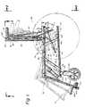
- Fig. 1 is a side elevational view of a wheelchair framework constructed in accordance with the present invention.
- Fig. 2 is a back elevational view taken along lines 2-2 of Fig. 1.
- Fig. 3 is a top plan view taken along lines 3-3 of Fig. 1.
- Fig. 4 is a side elevational view taken along lines 4-4 of Fig. 3.
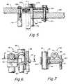
- Fig. 5 is an enlarged cross-sectional view taken along lines 5-5 of Fig. 3.
- Fig. 6 is an enlarged cross-sectional view taken along lines 6-6 of Fig. 2.
- Fig. 7 is a cross-sectional view taken along lines 7-7 of Fig. 6.
- With reference to Figs. 1-3 of the drawings, the unique wheelchair framework of the invention is shown generally by
reference 10. The framework includes two generally parallel spaced-apart sideframes folding assembly 16. - With particular reference to Figs. 1 and 4, each sideframe includes a
base frame section 20 and aseat frame section 22. The sections consist of linear structural elements preferably of lightweight extruded aluminum, alloys of titanium or aluminum, or composite plastic. Each section includes a track means which, as shown, comprises anundercut slot 24 extending laterally along at least one, and preferably two, opposing frame section sides. - Most conveniently, the slots extend throughout the length of the
inner face 38 andouter face 39 of each section. Each slot has a cross-sectional shape corresponding to the outline of aslidable fastener 25 which is retained therein. The slots preferably have a T-shaped cross-section whereby the slidable fasteners may comprise a conventional square nut having a threaded opening accessible through said slot. - As will be hereinafter apparent, the number of slidable fasteners contained in each track means will be dictated by the frame section connections and the requirements of supplemental engagement means. Further, it will be appreciated that track means may include slotted strips or sliding bolt means and the like which may be secured to one or more of the frame section faces.
- The aforementioned base section functions as the sideframe foundation and supports the wheelchair wheels. The seat section is positioned above, and generally coextensively with, the base section. It is supported by a brace means which also allows movement relative to the base section. The seat section also provides support for a seat (not shown). If a folding seat with enlarged edges is used, as set forth in the above-referenced parent application, the seat section may include seat engagement means shown as
seat keyway 34. - With reference to Figs. 3 and 4, the brace means includes at least one
elongated brace member 41 having an upper end attached to the seat section and a lower end attached to the base section. To effect a sound sideframe structure, two spaced-apart brace members are preferably used per sideframe. It is also helpful if the members incline toward each other to facilitate their dual axis function as will be hereinafter described. - The opposing ends of each brace member are provided with a pivot
joint assembly 44. Such assembly may be any one or combination of a ball joint, universal joint, pivot shaft, swivel means and hinge means. As shown, the assembly includes a ball joint means having ajoint shaft 45 which extends intoslot 24 for securement with aslide fastener 25. Alternatively, the joint shaft may pass entirely through each section for securement withexternal fastener 46. - Each brace member may include longitudinal adjustment means known in the art. For example,
inner rod 47 that merges into the ball joint means may be threaded at its end portion for engagement with corresponding threads onmember 41. This provides a simple means for axial adjustment and facilitates variable spacing and inclination of the brace members between the frame sections. - To strengthen the sideframe structure, the brace means may include
side plates 50. The side plates are flat elongated structural elements which are preferably aligned and coextensive with each brace member. Each plate includes opposing end apertures through which extend respectivejoint shafts 45. The plates are pivotally secured to each shaft by the aforementionedexternal fasteners 46. In this way, when the seat section is moved, the side plates will rotate about each respective joint shaft. - The side plates may also be used to help support a
seat mounting unit 62 for attachment to seat extender means 54. The seat extender means includes aseat housing 55 through which reciprocatesseat shaft 56. The shaft may be locked at any position upon release of a seat locking means shown ascatch 57. A seat actuating means shown astrigger 58 andcable 60 operate the catch. The trigger is mounted inpanel 59 for finger movement adjacentleft handle bar 118.Cable 60 is used to transmit trigger movement to the catch. It will be understood that the extender means may be operated by other actuating means known in the art such as hydraulic, pneumatic or electro-magnetic means. - With particular reference to Figs. 6 and 7,
seat mounting unit 62 is shown as being rotatably connected to braceblock 63 byseat axle 64. The axle extends transversly from side plate axle opening 51 throughhousing collar 65 into the brace block. Astay pin 66 secures the axle to the brace block. - The
movable seat shaft 56 includesseat connector end 68. Across axle 70 extends betweenconnector plates 72 through a transverse aperture in the connector end. The plates are adjustably secured withplate fasteners 74 andslide fasteners 25 to a location proximate the back portion of each seat section. - Actuation of
trigger 58 will open catch 57 viacable 60 andrelease shaft 56 for axial movement throughhousing 55. With reference to Fig. 1, application of downward force proximate said back portion (arrow F) will allow theseat frame section 22 to rotate (arrow R) and move slightly forward. A dual axis of rotation located at each joint shaft seat section connection is created by the above actions and structure. Note that both axis will also move in a slight arc as a result of rotation about each joint shaft in thelower base section 20. - With the above arrangement, the amount of (seat) inclination is readily and conveniently controlled simply by trigger movement with a finger from a user's hand that may be simultaneously grasping
handle bar 118. It will also be appreciated that the degree of inclination per amount of back portion downward movement can be adjustably altered by varying the angularity and length of the side plates and corresponding brace members. - As previously indicated, both sideframes are mirror images of each other including all the aforementioned parts. Therefore, like parts are coextensive to each other and all movements described above with respect to
sideframe 14, will apply equally tosideframe 12. This will result in unified movement of the wheelchair patient support parts including the seat, backrest means, footrest and arms. Particulars of those parts not shown or discussed herein may be obtained by reference to the aforementioned parent application. - An additional desirable feature of the invention is the ability to adjust the backrest tilt independent of seat inclination. As shown in Figs. 1, 2 and 4, the backrest includes a pair of upstanding backrest bars 90. Each bar is pivotally joined to a
respective seat section 22 by link means 35. - Although various types of H brackets, yoke bars, clamps and braces could be used for the link means, the preferred means is shown as
connector elements 36 withlink fasteners 37. The connector elements are flat generally rectangular plates having spaced-apart orifices through which the link fasteners extend. The link fasteners preferably comprise bolts which are threaded to engage the female threads of theslidable fasteners 25. Other types of link fasteners could be used as dictated by the particular link means and track means being utilized such that the invention should not be limited by any specific fastening system. - The link fastener orifices are arranged to include at least two at a securement end portion of each connector element and one at an opposing pivot end portion thereof. As so arranged, link fasteners extending through the securement end orifices into engagement with the respective slidable fasteners, will serve mainly to firmly fix the element to the end of a bar or frame section. However, the link fastener extending through the pivot end orifice into engagement with a slidable fastener on the adjacent connecting bar or frame section, will function as a pivot until tightened. Thus, an angularly adjustable joint is formed between the connecting bar or frame section. Further, the joint will be longitudinally adjustable as a result of the slidable fastener on the adjacent bar or frame section. Still further, the connector elements can be reversed for allowing either bar or frame section to be pivotable.
- Since the cross-sectional shape of the backrest bars and seat sections are substantially identical, the link means can include the above-described
connector elements 36 withlink fasteners 37 and pivot end fasteners 37'. As shown, the connector elements are positioned at opposing sides of the lower end of each backrest bar.Link fasteners 37 engage corresponding slidable fasteners contained withinslots 24. The pivot portion of each connector element extends beyond the end of the backrest bar and overlies respective inner and outer faces of the seat section. Pivot link fasteners are then used to engage corresponding slidable fasteners in the seat section slots. - To strengthen the backrest joints and provide for convenient adjustability, a backrest extender means 80 is used to pivotally interconnect the backrest bar and seat section. Such means is identical to the seat extender means except for connection variations. A
slider block 81 is adjustably secured to slide fasteners in the seat section. Acollar axle 82 extends transversly throughcollar 83 ofbackrest housing 84. An end of the axle threadably engages corresponding threads in the slider block thereby forming an axis about which the backrest housing can rotate. Backrest shaft 85 reciprocates within the housing and includesbackrest connector end 86.Cross axle 87 extends through a transverse aperture in the connector end and threadably engagesspacer block 88. The block is adjustably secured to thebackrest bar 90 via engagement of block fasteners with backrest slide fasteners.- A backrest locking means includes
clip 138 for releasably locking theshaft 85. The backrest actuating means comprisescable 140 which connects the clip to trigger 141 which is mounted onpanel 142. The panel is attached to the upper backrest bar adjacentright handle 121. This provides a convenient finger release and allows for angular adjustment of the backrest in the same manner as described with respect to the seat extender means. - Note that inclination of the seat sections by application of force F may be accomplished through the handles and backrest bars. Further, it will be appreciated that the backrest housing and backrest shaft connections may be reversed whereby the housing may connect with the backrest bar and the shaft may connect with the seat section. Similarly, the seat housing and seat shaft connections may also be reversed.
- To provide upper backrest support, a pair of hinged
support arms support pin 97. The arms include a lock means to releasably maintain an open colinear position. The lock means compriseshook 98 at an extended portion ofarm 95 that engages a hook pin 99 projecting fromarm 96 when the arms are in longitudinal alignment. - The opposing outer end of each support arm is hinged to a respective arm block 101,102. Each block is provided with
arm fasteners 103 that engage slidable fasteners in the backrest bars. This connection allows adjustment and movement of the support arms up and down the backrest bars. - The backrest bars further include
backrest keyways 104. A back support structure, such as that set forth in the parent application, includes enlarged opposing side edges which slide into the keyways at the open end of each backrest bar. The back support structure can be rigid as with a non-collapsing wheelchair, or it can be flexible for a wheelchair that folds together. - The
folding assembly 16 of the invention is most conveniently attached to opposing sideframes via the above-described brace means. This eliminates additional multiple connections to the frame sections, saves cost, minimizes weight and prevents interference with sideframe adjustability. The assembly includes at least one pair of hinged spacer bars having a releasable latching means for securing the hinged bars in an open position. - With reference to Figs. 2 and 3, an illustative folding assembly is shown comprising a pair of upper spacer bars 160,161 and lower spacer bars 162,163. Each pair includes overlapping inner end portions having aligned openings through which a
pivot shaft 164 extends. The shaft is secured bynut 165. The outer ends of each bar are secured to respective opposingbrace members 41. - The bar connections to each brace member preferably occur adjacent to the ends of the member. In this way, greater leverage occurs to pivot the assembly and move the sideframes in and out. Also, as a result of the bars being connected at spaced-apart locations on the brace member, a stronger more stable alignment occurs between the opposing sideframes.
- The pivot shaft is located at the inner end of outer bars 161,163 and at a location inwardly offset from the end of inner bars 160,162 The offset portions of the inner bars thereby form locking
arms 168. The arms swing beneath overlapping inner end portions ofouter bars - To secure the bars in straight alignment, the outer end of each locking arm is provided with a
recess 167. Offset inwardly from the inner end of the outer bars arelatch slots 171. Aspring opening 172 extends longitudinally inwardly from the outer bar to intersect and pass beyond the latch slots. That part of the opening beyond the slots containsspring 173. - While the spring is constrained in the containment part, a
latch rod 170 is inserted through theslots 171. Upon release, the spring will function to bias inwardly the latch rod so the rod will firmly engagerecess 167 when the bars are in straight alignment. - A
leverage rod 174 is secured byrod fastener 175 between the outer bars in a parallel and spaced-apart relationship to the latch rod. The leverage rod supports the outer bars and provides hand leverage when grasping the latch rod and moving it against the force ofspring 173. As shown by arrow L in Fig. 5, with the latch rod withdrawn fromrecess 167, the hinged bars may pivot toward each other and draw the sideframes together. - Each seat section may include a
front leg section 23. The leg section is preferably identical in construction to the base section. It includesslots 24 containingslide fasteners 25 for engagement with link means 35. - The leg section is attached to the front end portion of each
base section 20 by opposing connector elements and fasteners in the same manner as with backrest bars 90. The leg joint produced thereby with pivot fastener 37' may be reinforced by an adjustable strut means 180. - As best shown in Figs. 1 and 4, the strut means includes a
first strut bar 181 pivotally connected at its upper end bystrut fastener 182 to a slide fastener inseat section 22. The opposing free end of the strut bar is secured tobracket 183 having a firstannular part 184. - A
second strut bar 185 is pivotally secured at its lower end bystrut fastener 186 to a slide fastener inleg section 23. It extends through thefirst part 184 to an upper end which is secured to ajunction part 187. The junction part includes a secondannular part 188 having aslide opening 189 through which the first strut bar extends. The slide opening can be restricted withknob 190 to engage the strut rod. - As the leg section is moved, as shown by arrows B in Fig. 4, the second strut bar will move through the first annular part and cause the second annular part to slide along the first strut bar. When the desired angular disposition of
leg section 23 is achieved,knob 190 will be tightened. This frictionally restrains further movement of the junction part along the first strut bar and secures the leg section in place. - The leg sections can include leg support means (not shown) and/or
footrest plates 124. Footrest blocks 122 withfasteners 123 are used to connect the plates to slide fasteners in the leg section. - To further exemplify the advantages of the invention, it will be appreciated that attachment of adjunct wheelchair assemblies (such as brake means, casters, armrests and body support pads) can all be accomplished with supplemental connector means in conjunction with the slidable fasteners of the unique bar and frame sections. Use of the above in cooperating relation with the track means, allows the supplemental connections to be semipermanent and adjustable. This feature together with the variable sideframe geometry, makes it possible for a single wheelchair to be adaptable for a wide variety of special needs and uses.
- To illustrate the above, note
conventional caster assemblies 114 which are secured to the forward portion ofbase section 20 by a caster block means. Such means provides a supplemental connector junction whereby a caster assembly is connected tocaster block 115. The block, in turn, includesblock fasteners 116 which engage slidable fasteners in the base section. The combined assembly can be moved, as desired, anywhere alongslot 24. - Similarly, handles 118, 121 are joined to the upper portion of respective backrest bars by supplemental means comprising a
handle connector block 119. The block is split to frictionally engage the tubular handle base. Threadedhandle fasteners 120 tighten the block to the handle. The fasteners also engage corresponding slidable fasteners in the backrest bars. - Conventional wheelchair drive wheels 107 (depicted in phantom in Figs. 1-4) are secured to each opposing base section. Axle plates 111 are adjustably secured to opposing sides of
base section 20 withplate fasteners 113. The plates include a threaded opening which engage the threads of the wheel axle (not shown). Note the plate and slide fastener connections permit adjustment of wheel location anywhere along the length of the base section which is not already occupied.
Claims (10)
- A wheelchair having a seat, backrest and wheels which are supported by two opposing structurally independent lateral sideframe structures (12,14), each sideframe structure comprising:
a base section (20);
a seat section (22) spaced-apart and movable on four axes of rotation (46) relative to said base section (20);
brace means (41) pivotally connecting each of said seat section (22) and said base section (20), said brace means comprising a first brace member (41) interconnecting said base section (20) with said seat section (22) and a second brace member (41) interconnecting said base section (20) with said seat section (22), each of said brace members (41) having opposing ends provided with joint means (44) for forming respective pivot connections with said base section (20) and said seat section (22); and characterized by said first brace member (41) interconnecting a back portion of said base section (20) with said seat section (22), and said second brace member (41) interconnecting a forward portion of said base section (20) with said seat section (22), so as to form a trapezium mechanism, whereby said seat section (22) being angularly movable on said four axes of rotation (46) relative to said base section (20); and a seat extender means (54) interconnecting said seat section (22) and one of said brace members (41) for regulating the angular displacement of said seat section (22) relative to said base section (20). - The sideframe of Claim 2 characterized in that said seat extender means (54) comprises a seat housing (55) with a seat shaft (56) moveable through said housing, either one of said housing (55) or shaft (56) connected to said one brace member (41) and either one of or other of said housing (55) or shaft (56) connected to said seat section (22), said seat extender means (54) including a seat locking means (57) for securing said shaft (56) at a selected position relative to said housing (55).
- The sideframe of Claim 2 characterized in that said brace members (41) are inclined toward each other, and said seat extender means (54) includes remote actuating means (58,60) for operating said locking means (57).
- The sideframes of Claim 3 characterized in that said brace means (41) includes side plates (50) pivotally connected to each of said base section (20) and seat section (22), each side plate (50) extending parallel and coextensively with a respective associated brace member (41).
- The sideframe of Claim 4 characterized in that said pivot joint assemblies (44) include a joint shaft (45) common to each side plate (50) and brace member (41) connection.
- The wheelchair of Claim 1, characterized by a folding assembly (160-165) connected to each sideframe for releasably spacing one sideframe from the other.
- The wheelchair of Claim 6 characterized in that said folding assembly (160-165) includes at least one pair of spacer bars (160,161) having pivotally connected inner end portions and outer ends attached to a respective sideframe.
- The wheelchair of Claim 7 characterized in that said outer ends are attached to said brace members (41).
- The wheelchair of Claim 1 characterized in that said backrest includes: a pair of backrest bars (90) each being pivotally connected to a respective seat section (22); and
a backrest extender means (80) pivotally interconnecting each backrest bar (90) with a respective seat section (22). - The wheelchair of Claim 9 characterized in that said backrest bars (90) include lateral slots (104) which contain slidable bar fasteners (25,103) and each of said backrest bars (90) are connected to a respective seat section (22) by backrest link means (36) that include link fasteners (37) which engage said slidable bar fasteners (25).
Applications Claiming Priority (2)
| Application Number | Priority Date | Filing Date | Title |
|---|---|---|---|
| US155998 | 1988-02-16 | ||
| US07/155,998US4966379A (en) | 1987-10-19 | 1988-02-16 | Reclinable wheelchair |
Publications (3)
| Publication Number | Publication Date |
|---|---|
| EP0329002A2 EP0329002A2 (en) | 1989-08-23 |
| EP0329002A3 EP0329002A3 (en) | 1990-02-07 |
| EP0329002B1true EP0329002B1 (en) | 1994-10-26 |
Family
ID=22557655
Family Applications (1)
| Application Number | Title | Priority Date | Filing Date |
|---|---|---|---|
| EP89102151AExpired - LifetimeEP0329002B1 (en) | 1988-02-16 | 1989-02-08 | Reclinable wheelchair |
Country Status (4)
| Country | Link |
|---|---|
| US (1) | US4966379A (en) |
| EP (1) | EP0329002B1 (en) |
| CA (1) | CA1293438C (en) |
| DE (1) | DE68918961T2 (en) |
Families Citing this family (54)
| Publication number | Priority date | Publication date | Assignee | Title |
|---|---|---|---|---|
| US5217239A (en)* | 1989-01-20 | 1993-06-08 | Linido B.V. | Wheelchair |
| US5172925A (en)* | 1989-06-09 | 1992-12-22 | Quickie Designs Inc. | Mobile prone stander with positioning chair |
| US5143391A (en)* | 1990-04-27 | 1992-09-01 | Medical Composite Technology | Modular wheelchair |
| NO301519B1 (en)* | 1991-05-07 | 1997-11-10 | Nippon Telegraph & Telephone | Movable chair |
| NL9100789A (en)* | 1991-05-08 | 1992-12-01 | Seenus Nl Bv R Van | WHEELCHAIR. |
| US5154438A (en)* | 1991-09-30 | 1992-10-13 | Barclay Hugh W | Tilting and folding wheelchair |
| DE9113085U1 (en)* | 1991-10-21 | 1991-12-12 | MEYRA Wilhelm Meyer GmbH & Co KG, 4925 Kalletal | wheelchair |
| US5267745A (en)* | 1991-11-08 | 1993-12-07 | Medical Composite Technology, Inc. | Wheelchair and wheelchair frame |
| US5286046A (en)* | 1991-11-25 | 1994-02-15 | Homecrest Industries Incorporated | Geriatric chair |
| US5328247A (en)* | 1992-04-29 | 1994-07-12 | Quickie Designs Inc. | Extendable leg rest assembly for a wheelchair |
| US5297021A (en)* | 1992-11-16 | 1994-03-22 | Koerlin James M | Zero shear recliner/tilt wheelchair seat |
| US5402544A (en)* | 1993-09-17 | 1995-04-04 | Easy Lift Care Products, Inc. | Combination chair and gurney |
| US5584082A (en)* | 1993-09-17 | 1996-12-17 | Easy Lift Care Products, Inc. | Convertible gurney |
| NL9301970A (en)* | 1993-11-15 | 1995-06-01 | Hendrik Jan Ordelman | Foldable wheelchair. |
| US5556157A (en)* | 1994-12-21 | 1996-09-17 | Wempe; Patrick L. | No-shear power recline system for wheelchairs |
| US5673967A (en)* | 1994-12-21 | 1997-10-07 | Wempe; Patrick L. | Apparatus for interconnecting a leg rest and wheelchair |
| US5590893A (en)* | 1994-12-28 | 1997-01-07 | No Limit Designs, Inc. | Wheelchair frame assembly |
| FR2742641B1 (en)* | 1995-12-21 | 1998-02-27 | Degonda Rehab Sa | STATIONARY OR ROLLING RECLINING SEAT DEVICE, ESPECIALLY FOR SICK OR HANDICAPPED |
| US5718442A (en)* | 1995-12-27 | 1998-02-17 | Mechanical Application Designs, Inc. | Power wheelchair with extended power seat frame tilt |
| US5722682A (en)* | 1996-06-27 | 1998-03-03 | Wang; Morgan | Foldable two-seater stroller |
| US5865457A (en)* | 1997-01-08 | 1999-02-02 | La-Z-Boy Incorporated | Wheeled health care chair |
| GB9709736D0 (en)* | 1997-05-14 | 1997-07-02 | Helping Hand Company Ledbury T | Improvements relating to chairs |
| US6129365A (en)* | 1997-07-01 | 2000-10-10 | Outrigger, Inc. | Inclined handle for wheeled case |
| US5971482A (en)* | 1997-10-02 | 1999-10-26 | Invacare Corporation | Constant center of gravity tiltable chair of a wheelchair |
| US6244662B1 (en)* | 1997-10-22 | 2001-06-12 | I.D.C. Medical | Elevator chair of adjustable seat depth |
| FR2769831B1 (en)* | 1997-10-22 | 2000-01-21 | Int Diffusion Consommateurs Id | LIFT ARMCHAIR WITH ADJUSTABLE SEAT DEPTH |
| US6257609B1 (en)* | 1998-03-27 | 2001-07-10 | O'neill, Sr. Theodore C. | Tilt-in-space wheelchair |
| US6126186A (en) | 1998-11-09 | 2000-10-03 | Invacare Corporation | Constant center of gravity tilt seat of a wheelchair |
| US6250661B1 (en) | 1998-11-13 | 2001-06-26 | Sunrise Medical Hhg Inc. | Tilt system for a powered wheelchair seat |
| US6086086A (en)* | 1999-05-11 | 2000-07-11 | Sunrise Medical Hhg Inc. | Stroller with tilt-in-space capability |
| US6264225B1 (en) | 1999-06-14 | 2001-07-24 | Sunrise Medical Hhg Inc. | Adjustable side frame and wheelchair with adjustable side frame |
| NL1012548C2 (en)* | 1999-07-09 | 2001-01-10 | Mediquip Holland B V | Wheelchair. |
| US6345835B1 (en)* | 2000-09-08 | 2002-02-12 | Convaid Products, Inc. | Vertically collapsible mobile chair with fixed tilting movement |
| TW506370U (en)* | 2001-06-12 | 2002-10-11 | Link Treasure Ltd | Folding structure of stroller |
| SE523441C2 (en)* | 2001-12-11 | 2004-04-20 | Etac Ab | Wheelchair with adjustable upper and lower frame |
| EP1635754A2 (en) | 2003-03-20 | 2006-03-22 | R82 A/S | Active wheelchair |
| US7296856B2 (en)* | 2003-10-08 | 2007-11-20 | Pride Mobility Products Corporation | Reclining seat with movable back support |
| US7854481B2 (en)* | 2004-06-15 | 2010-12-21 | Star Cushion Products, Inc. | Methods and apparatus for assembling a wheel chair |
| US20060076814A1 (en)* | 2004-10-08 | 2006-04-13 | Ivan Samila | Adjustable backrest on personal mobility aid |
| US7360841B2 (en)* | 2004-10-20 | 2008-04-22 | Pride Mobility Products Corporation | Articulating leg rest for a wheelchair |
| WO2006045316A1 (en)* | 2004-10-29 | 2006-05-04 | R82 A/S | Comfort wheelchair |
| US7131154B2 (en)* | 2005-02-24 | 2006-11-07 | Wood Lark Circle, Inc. | Mobile transport device |
| US20070085301A1 (en)* | 2005-10-18 | 2007-04-19 | Watkins Mervyn M | Center-of-gravity tilt-in-space wheelchair |
| DE202006009579U1 (en)* | 2006-06-17 | 2007-07-26 | Rebotec Rehabilitationsmittel Gmbh | Wheelchair for the sick or disabled for use as a shower, toilet or nursing chair |
| US7896385B2 (en)* | 2007-09-21 | 2011-03-01 | Michael Every | Foldable wheelchair |
| WO2009080347A2 (en)* | 2007-12-21 | 2009-07-02 | Sunrise Medical Gmbh & Co. Kg | Wheelchair frame and wheelchair with cross-brace |
| ATE496605T1 (en) | 2008-10-10 | 2011-02-15 | Sunrise Medical Gmbh & Co Kg | WHEELCHAIR WITH FOOTREST |
| WO2010102028A1 (en) | 2009-03-03 | 2010-09-10 | Hector Melvin G | Structure, components and method for constructing and operating an automatically self locking manually propelled vehicle such as a wheel chair |
| US8403420B2 (en)* | 2009-09-14 | 2013-03-26 | Ramon Billescas | Reversible footrest |
| WO2011100556A2 (en) | 2010-02-11 | 2011-08-18 | Snow Solutions Llc | Convertible wheelchairs with movable carriages for transferring patients to/from the wheelchairs |
| US8459660B2 (en)* | 2010-12-04 | 2013-06-11 | Livingston Innovations LLC. | Multi function patient transport |
| US20120161484A1 (en)* | 2010-12-28 | 2012-06-28 | Taiwan An I Co., Ltd. | Wheelchair tilting mechanism |
| US20140117644A1 (en)* | 2012-05-14 | 2014-05-01 | Dave Paul | Wheelchair Having Two Metastable Positions |
| EP3795128B1 (en)* | 2019-09-17 | 2022-10-26 | MBL Poland Sp. z o.o. | Wheelchair |
Family Cites Families (16)
| Publication number | Priority date | Publication date | Assignee | Title |
|---|---|---|---|---|
| US3191990A (en)* | 1962-05-31 | 1965-06-29 | Rugg Donald Edwin | Reclining mechanism for wheelchairs and the like |
| SE300672B (en)* | 1965-09-02 | 1968-05-06 | Redev Ab | |
| SE343208B (en)* | 1970-07-06 | 1972-03-06 | K Wrethander | |
| US3964786A (en)* | 1974-12-20 | 1976-06-22 | David Mashuda | Mechanized wheelchair |
| AT354003B (en)* | 1976-01-15 | 1979-12-10 | Herlag Holzwarenfabrik Kg | STROLLER |
| US4046418A (en)* | 1976-07-21 | 1977-09-06 | Royal Smith | Wheelchairs |
| FR2399822A1 (en)* | 1977-08-09 | 1979-03-09 | Dupont Lit Sa | Folding wheel chair for handicapped people - consists of frame on two drive wheels, with seat mounted by parallel arms raised and lowered by jack |
| US4335900A (en)* | 1978-07-24 | 1982-06-22 | Henry Fleischer | Collapsible frames for baby carriers |
| US4231614A (en)* | 1978-10-27 | 1980-11-04 | Shaffer Gene P | Wheelchair |
| FR2515508A1 (en)* | 1981-11-05 | 1983-05-06 | Michel Fayolle | Motorised sitting to standing lifting mechanism for armchair - has two motors and links which raise chair and articulates seat and back portions from normal sitting position to near vertical |
| FR2546746B1 (en)* | 1983-05-30 | 1988-10-14 | Lacoste Sa Ets | FOLDABLE WHEELCHAIR |
| US4613151A (en)* | 1984-02-16 | 1986-09-23 | Kielczewski William J | High/low extension-lift power wheelchair |
| SE458502B (en)* | 1984-04-19 | 1989-04-10 | Torgny Jan Ab Jatab | SEAT AND WHEELCHAIR HANDLES TO HANDLE A PERSON WITH LIMITED MOBILITY |
| US4555121A (en)* | 1984-09-20 | 1985-11-26 | Invacare Corporation | Invalid's chair to facilitate transfer to an automobile |
| US4632450A (en)* | 1984-11-21 | 1986-12-30 | Cambridge Technologies, Inc. | Convertible wheelchair/litter |
| US4741547A (en)* | 1987-05-14 | 1988-05-03 | Tholkes Alan L | Folding wheelchair |
- 1988
- 1988-02-16USUS07/155,998patent/US4966379A/ennot_activeExpired - Lifetime
- 1989
- 1989-02-08DEDE68918961Tpatent/DE68918961T2/ennot_activeExpired - Fee Related
- 1989-02-08EPEP89102151Apatent/EP0329002B1/ennot_activeExpired - Lifetime
- 1989-02-08CACA000590402Apatent/CA1293438C/ennot_activeExpired - Lifetime
Also Published As
| Publication number | Publication date |
|---|---|
| US4966379A (en) | 1990-10-30 |
| DE68918961D1 (en) | 1994-12-01 |
| DE68918961T2 (en) | 1995-05-11 |
| CA1293438C (en) | 1991-12-24 |
| EP0329002A3 (en) | 1990-02-07 |
| EP0329002A2 (en) | 1989-08-23 |
Similar Documents
| Publication | Publication Date | Title |
|---|---|---|
| EP0329002B1 (en) | Reclinable wheelchair | |
| US5020816A (en) | Adjustable frame wheelchair | |
| EP0312969A2 (en) | Adjustable frame wheelchair | |
| US4648619A (en) | Collapsible wheelchair chassis | |
| US8262117B2 (en) | Wheelchair comprising a foot support | |
| US5195803A (en) | Reclining seat back assembly for a wheelchair | |
| US5217239A (en) | Wheelchair | |
| US5228747A (en) | Seating system | |
| US6296265B1 (en) | Recliner wheelchair having adjustable pivot point | |
| US20110175329A1 (en) | Light weight foldable and customizable wheelchair | |
| US20020101108A1 (en) | Compact foldable massage chair | |
| JP3493000B2 (en) | Wheelchair back recliner kit | |
| US6352275B1 (en) | Wheelchair | |
| US7192042B2 (en) | Adjustable seating system | |
| JP2950850B2 (en) | Folding wheelchair | |
| EP1824724B1 (en) | Foldable wheelchair and axle plate therefor | |
| EP0608964B1 (en) | Reclining seat back assembly for a wheelchair | |
| EP0384499B1 (en) | Wheelchair | |
| EP0450735A2 (en) | Seat | |
| EP0908167A2 (en) | Reversible seat for front wheel drive and rear wheel drive power wheelchair having stepless angular adjustment | |
| RU2144811C1 (en) | Wheeled armchair | |
| GB2317861A (en) | Wheelchair |
Legal Events
| Date | Code | Title | Description |
|---|---|---|---|
| PUAI | Public reference made under article 153(3) epc to a published international application that has entered the european phase | Free format text:ORIGINAL CODE: 0009012 | |
| AK | Designated contracting states | Kind code of ref document:A2 Designated state(s):DE FR GB NL SE | |
| PUAL | Search report despatched | Free format text:ORIGINAL CODE: 0009013 | |
| AK | Designated contracting states | Kind code of ref document:A3 Designated state(s):DE FR GB NL SE | |
| 17P | Request for examination filed | Effective date:19900716 | |
| 17Q | First examination report despatched | Effective date:19910911 | |
| GRAA | (expected) grant | Free format text:ORIGINAL CODE: 0009210 | |
| AK | Designated contracting states | Kind code of ref document:B1 Designated state(s):DE FR GB NL SE | |
| REF | Corresponds to: | Ref document number:68918961 Country of ref document:DE Date of ref document:19941201 | |
| EAL | Se: european patent in force in sweden | Ref document number:89102151.1 | |
| ET | Fr: translation filed | ||
| PLBE | No opposition filed within time limit | Free format text:ORIGINAL CODE: 0009261 | |
| STAA | Information on the status of an ep patent application or granted ep patent | Free format text:STATUS: NO OPPOSITION FILED WITHIN TIME LIMIT | |
| 26N | No opposition filed | ||
| PGFP | Annual fee paid to national office [announced via postgrant information from national office to epo] | Ref country code:GB Payment date:19990226 Year of fee payment:11 | |
| PGFP | Annual fee paid to national office [announced via postgrant information from national office to epo] | Ref country code:FR Payment date:19990301 Year of fee payment:11 | |
| PGFP | Annual fee paid to national office [announced via postgrant information from national office to epo] | Ref country code:NL Payment date:19990315 Year of fee payment:11 | |
| PG25 | Lapsed in a contracting state [announced via postgrant information from national office to epo] | Ref country code:GB Free format text:LAPSE BECAUSE OF NON-PAYMENT OF DUE FEES Effective date:20000208 | |
| PGFP | Annual fee paid to national office [announced via postgrant information from national office to epo] | Ref country code:SE Payment date:20000208 Year of fee payment:12 | |
| PGFP | Annual fee paid to national office [announced via postgrant information from national office to epo] | Ref country code:DE Payment date:20000214 Year of fee payment:12 | |
| PG25 | Lapsed in a contracting state [announced via postgrant information from national office to epo] | Ref country code:NL Free format text:LAPSE BECAUSE OF NON-PAYMENT OF DUE FEES Effective date:20000901 | |
| GBPC | Gb: european patent ceased through non-payment of renewal fee | Effective date:20000208 | |
| PG25 | Lapsed in a contracting state [announced via postgrant information from national office to epo] | Ref country code:FR Free format text:LAPSE BECAUSE OF NON-PAYMENT OF DUE FEES Effective date:20001031 | |
| NLV4 | Nl: lapsed or anulled due to non-payment of the annual fee | Effective date:20000901 | |
| REG | Reference to a national code | Ref country code:FR Ref legal event code:ST | |
| PG25 | Lapsed in a contracting state [announced via postgrant information from national office to epo] | Ref country code:SE Free format text:LAPSE BECAUSE OF NON-PAYMENT OF DUE FEES Effective date:20010209 | |
| EUG | Se: european patent has lapsed | Ref document number:89102151.1 | |
| PG25 | Lapsed in a contracting state [announced via postgrant information from national office to epo] | Ref country code:DE Free format text:LAPSE BECAUSE OF NON-PAYMENT OF DUE FEES Effective date:20011201 |