EP0327949B1 - Alignment stage device - Google Patents
Alignment stage deviceDownload PDFInfo
- Publication number
- EP0327949B1 EP0327949B1EP89101756AEP89101756AEP0327949B1EP 0327949 B1EP0327949 B1EP 0327949B1EP 89101756 AEP89101756 AEP 89101756AEP 89101756 AEP89101756 AEP 89101756AEP 0327949 B1EP0327949 B1EP 0327949B1
- Authority
- EP
- European Patent Office
- Prior art keywords
- stage
- alignment
- drive
- axis
- base
- Prior art date
- Legal status (The legal status is an assumption and is not a legal conclusion. Google has not performed a legal analysis and makes no representation as to the accuracy of the status listed.)
- Expired - Lifetime
Links
- 230000033001locomotionEffects0.000claimsdescription21
- 229910000831SteelInorganic materials0.000claimsdescription15
- 239000010959steelSubstances0.000claimsdescription15
- 230000036544postureEffects0.000description5
- 239000004065semiconductorSubstances0.000description4
- 230000005540biological transmissionEffects0.000description3
- 238000000034methodMethods0.000description3
- 230000002441reversible effectEffects0.000description3
- 238000010586diagramMethods0.000description1
- 238000004519manufacturing processMethods0.000description1
- 230000036316preloadEffects0.000description1
Images


Classifications
- H—ELECTRICITY
- H01—ELECTRIC ELEMENTS
- H01L—SEMICONDUCTOR DEVICES NOT COVERED BY CLASS H10
- H01L21/00—Processes or apparatus adapted for the manufacture or treatment of semiconductor or solid state devices or of parts thereof
- G—PHYSICS
- G03—PHOTOGRAPHY; CINEMATOGRAPHY; ANALOGOUS TECHNIQUES USING WAVES OTHER THAN OPTICAL WAVES; ELECTROGRAPHY; HOLOGRAPHY
- G03F—PHOTOMECHANICAL PRODUCTION OF TEXTURED OR PATTERNED SURFACES, e.g. FOR PRINTING, FOR PROCESSING OF SEMICONDUCTOR DEVICES; MATERIALS THEREFOR; ORIGINALS THEREFOR; APPARATUS SPECIALLY ADAPTED THEREFOR
- G03F7/00—Photomechanical, e.g. photolithographic, production of textured or patterned surfaces, e.g. printing surfaces; Materials therefor, e.g. comprising photoresists; Apparatus specially adapted therefor
- G03F7/70—Microphotolithographic exposure; Apparatus therefor
- G03F7/70691—Handling of masks or workpieces
- G03F7/70716—Stages
- G03F7/70725—Stages control
- G—PHYSICS
- G03—PHOTOGRAPHY; CINEMATOGRAPHY; ANALOGOUS TECHNIQUES USING WAVES OTHER THAN OPTICAL WAVES; ELECTROGRAPHY; HOLOGRAPHY
- G03F—PHOTOMECHANICAL PRODUCTION OF TEXTURED OR PATTERNED SURFACES, e.g. FOR PRINTING, FOR PROCESSING OF SEMICONDUCTOR DEVICES; MATERIALS THEREFOR; ORIGINALS THEREFOR; APPARATUS SPECIALLY ADAPTED THEREFOR
- G03F7/00—Photomechanical, e.g. photolithographic, production of textured or patterned surfaces, e.g. printing surfaces; Materials therefor, e.g. comprising photoresists; Apparatus specially adapted therefor
- G03F7/70—Microphotolithographic exposure; Apparatus therefor
- G03F7/70691—Handling of masks or workpieces
- G03F7/70758—Drive means, e.g. actuators, motors for long- or short-stroke modules or fine or coarse driving
- H—ELECTRICITY
- H01—ELECTRIC ELEMENTS
- H01L—SEMICONDUCTOR DEVICES NOT COVERED BY CLASS H10
- H01L21/00—Processes or apparatus adapted for the manufacture or treatment of semiconductor or solid state devices or of parts thereof
- H01L21/67—Apparatus specially adapted for handling semiconductor or electric solid state devices during manufacture or treatment thereof; Apparatus specially adapted for handling wafers during manufacture or treatment of semiconductor or electric solid state devices or components ; Apparatus not specifically provided for elsewhere
- H01L21/68—Apparatus specially adapted for handling semiconductor or electric solid state devices during manufacture or treatment thereof; Apparatus specially adapted for handling wafers during manufacture or treatment of semiconductor or electric solid state devices or components ; Apparatus not specifically provided for elsewhere for positioning, orientation or alignment
Definitions
- the present inventionrelates to an alignment stage device capable of aligning the reticle or mask, which has been set on the exposure means in the course of manufacturing semiconductor elements, for example, relative to the projection lenses and the like.
- the aligning of the reticles or masks which are used to produce the semiconductor elementsis usually attained by the alignment stage device which provides motions in plural degree of freedom by plural stages to precisely align the reticles or masks. More specifically, the alignment stage device has X and y stages which can move with the precision of micrometer order along X and y axes perpendicular to each other on a horizontal plane, and a ⁇ stage which can rotate round an axis perpendicular to the horizontal plane. When movements of these stages are combined with one another, the reticle or mask set on this alignment stage device can be aligned relative to the projection lenses and the like.
- x, y and ⁇ stagesare mounted one upon the other and each of them is guided in one direction by a pair of guide members.
- the height of the whole alignment stage devicetherefore, equals to the sum of thicknesses of x, y and ⁇ stages and heights of stages bases for supporting x, y and ⁇ stages.
- the alignment stage deviceneeds a large number of parts to guide these stages.
- the object of the present inventionis to provide an alignment stage device, smaller in size, capable of aligning the reticles or masks with higher accuracy.
- the second and third stagescan be arranged in the first stage on a same plane.
- the whole thickness of these stagesequals to that of one of these stages, thereby enabling the whole alignment stage device to be made smaller in size.
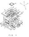
- Fig. 1is a perspective view showing an example of the alignment stage device of the present invention dismantled.
- This alignment stage devicecan be used as a reticle stage for producing semiconductor elements and it may be applied to machine tools as well.
- the alignment stage devicehas base 1 made rectangular by a thick plate.
- Two support stands 2 and 2are erected from the upper surface of base 1 on both sides thereof and opposed to each other to horizontally support y stage 5 which is a first stage made as a substantially square frame.
- Two y stage guides 3are formed along each of those opposed upper corners of support stands 2 and 2 to guide y stage 5 along axis of coordinate A.
- This y stage 5is driven in the direction of axis y by reversible DC servomotor 4 fixed to base 1.
- Rectangular rod-like drive slider 6which is pressed from above against shaft 4a of drive motor 4 at a right angle is fixed to y stage 5 to drive y stage 5 in the direction of axis y.
- friction drive slider 6is pressed against shaft 4a by preload applied from the usual friction drive system to prevent shaft 4a from being slid and drive bar 6 from becoming unsteady and being back-rushed. More specifically, shaft 4a is pressed against friction drive slider 6 by preloader 20 and friction drive slider 6 is held between shaft 4a and back up roller 21. Therefore, the rotating motion of shaft 4a is changed to rectilinear motion by the friction drive system to rectilinearly drive friction drive slider 6, so that y stage can be moved in the direction of axis y of a coordinate shown by A in Fig. 1. This movement of y stage 5 can be detected by a y axis sensor (not shown) and the position of y stage 5 can be feedback-controlled responsive to the result thus detected.
- x stage 7similar to y stage 5 and made by a square frame plate serving as a second stage is arranged in the center opening of y stage 5.
- Four guides 8are located between x and y stages 7 and 5 to guide x stage 7 relative to y stage 5 in the direction of axis x.
- Friction drive slider 9is extended outward from x stage 7 and pressed against shaft 10a of reversible DC servomotor 10, which is fixed to y stage 5, by a same friction drive system as shown in Fig. 2. This prevents shaft 10a from sliding relative to friction drive slider 9, so that x stage 7 can be moved in the direction of axis x of coordinate A when shaft 10a is rotated.
- the movement of x stage 7can be detected by an x axis sensor (not shown) and the position of x stage 7 can be feedback-controlled according to the result thus detected.
- ⁇ stage 11which serves as a third stage is arranged in the center opening of x stage 7.
- This ⁇ stage 11has stands 11a, on which reticle (or mask) 14 is mounted, in the center thereof and each of these stands 11a is provided with an opening 11b communicated with a vacuum source (not shown) to fix reticle 14 by vacuum suction.
- ⁇ stage 11is rotatably attached to x stage 7 through three guides 13 and it is rotated in a small range round an axis perpendicular to the plane, on which x stage 7 is positioned, by means of DC servomotor 12 attached onto x stage 7.
- ⁇ stage 11can be rotated round axial lines parallel to axes x and y and also moved in the direction of axis z by means of z stage 15 which serves as a fourth stage.
- z stage 15made by a thick plate as a square frame and arranged between support stands 2 and 2 on base 1 and under ⁇ stage 11 can be moved up and down and tilted as well.
- Three steel balls 15a freely rotatable at their certain positionsare arranged on the upper surface of z stage 15 and ⁇ stage 11 is supported on z stage 15 through these steel balls 15a.
- Steel balls 15aare contacted with both of ⁇ and z stages 11 and 15 and can transmit the movement of z stage 15 to ⁇ stage 11.
- ⁇ stage 11is thus moved up and down and tilted relative to base 1, following the movement of z stage 15. Further, ⁇ stage 11 can rotate on the upper surface of z stage 15 through these steel balls 15a.
- steel balls 15aserve as ball bearings and the rotation of ⁇ stage 11 is not transmitted to z stage 15.
- z stage 15is supported by z stage drive systems 16, which are located at three apexes of a triangular on base 1, in such a manner that it can be linearly moved in the direction of axis z or rotated round axial lines parallel to axes x and y or tilted relative to base 1.
- Each of drive systems 16includes reversible DC servomotor 17 fixed to base 1 to drive z stage 15, slider 19 linearly movable on the upper surface of base 1 due to the rotation of shaft 17b of motor 17, slope 18 formed on slider 19 and cam follower 15b attached to z stage 15 and contacted with slope 18.
- Z stage 15is supported on base 1 by slopes 18 on sliders 19 of z stage drive systems 16 and cam followers 15b.
- Z stage drive motor 17is connected in this case to shaft 17b through harmonic drive reduction system 17a, for example, to enable shaft 17b to receive reduced number of rotation from motor 17.
- Drive motor 17may be connected directly to shaft 17b.
- a ball nut screwis formed round the outer circumference of shaft 17b while a ball nut which can be screwed onto the ball nut screw is fixed to slider 19, so that the rotation of drive motor 17 can be changed to the rectilinear motion of slider 19 due to these screw and nut.
- Three sliders 19can be thus moved on base 1 at the same time or independently of the others by drive motor 17 through its shaft 17b.
- z stage 15is moved in the direction of axis z, up and down in Figs. 1 and 3 or tilted, that is, rotated round axial lines parallel to axes x and y.
- Fig. 3shows z stage 15 tilted relative to base 1 to tilt ⁇ stage 11 through steel balls 15a.
- arc portions 11care formed along the outer rim of ⁇ stage (Fig. 6) to rotatably guide ⁇ stage round an axial line perpendicular to that plane on which ⁇ stage is positioned, and ⁇ stage 11 is supported at these arc portions 11c by x stage 7 through guides 13.
- the curved portions 11ccan have different radii of curvatures.
- each of guides 13includes forked bracket 30 fixed to x stage 7, strut 31 supported by bracket 30 at both ends thereof, and guide ring 33 attached to strut 31 through ball bushing 32 in which a plurality of balls 32a are freely rotatably housed, the outer circumference of this guide ring having spherical face 33a when sectioned in the direction of its axial line.
- This guide ring 33can freely rotate round strut 30 due to ball bushing 32 and also move along strut 30 in the direction of its axial line.
- each of opposed arms 30a of bracket 30is provided with slit 29 which is directed toward the center of ⁇ stage 11, and each end of struts 31 is inserted into this slit 29.
- strut 31is urged in the longitudinal direction of slit 29 or toward the center of ⁇ stage 11 by means of spring 28 whose one end is fixed to connecting section 30b of bracket 30.
- the direction in which strut 31 is urged by spring 28is represented by arrow B in Figs. 5 and 6.
- ⁇ stageis held by three guides 13 at three arc portions 11c thereof.
- Struts 31 of stage guides 13are urged toward the center of ⁇ stage by means of springs 28 in this case. Therefore, guide rings 33 push arc portions 11c of ⁇ stage 11 toward the center of ⁇ stage 11.
- guide rings 33hold ⁇ stage 11 while being rotated by friction force caused between their spherical faces 33a and arc portions 11c of ⁇ stage 11. Further, the outer circumference of each of those guide rings 33 which urge arc portions 11c of ⁇ stage 11 is formed as spherical face 33a.
- stage guides 13can follow the movement of ⁇ stage 11 to reliably hold ⁇ stage 11 at an accurate position.
- each of struts 31has been urged toward the center of ⁇ stage 11 by means of spring 28 in this example, it may be arranged instead of using springs 28 that each of guide rings 33 is made of rubber and that struts 31 are urged by the elasticity of these rubber-made guide rings 33.
- ⁇ stage 11has drive slider 34 projected from the outer rim of ⁇ stage 11 and made as a rectangular plate.
- ⁇ stage 11is rotated in a certain angular range round an axial line perpendicular to that plane, on which ⁇ stage 11 is positioned, by means of ⁇ stage drive system 35 through drive slider 34.
- ⁇ stage drive system 35serves as a linear actuator comprising feed screw 37 horizontally positioned and connected to drive motor 12 which is fixed to x stage (see Fig. 1), and nut member 38 screwed onto feed screw 37.
- guide rail 7ais fixed onto the upper surface of x stage 7 along the axial line of feed screw 37 and cross roll table 38a (from which rollers are omitted in Figs. 10 and 11) which is guided by guide rail 7a is formed integral to that side of nut member 38 which faces x stage 7.
- drive motor 12see Fig. 1
- feed screw 37is rotated.
- Nut member 38 screwed onto feed screw 37is thus guided by rail 7a to move in the axial direction of feed screw 37.
- Transmission system 36which serves to transmit the movement of nut member 38 in the axial direction of feed screw 37 to drive slider 34 includes a pair of tongue pieces 42 and 43 projected from both ends of nut member 38 toward drive slider 34 or ⁇ stage 11, and push members 44 and 45 arranged on both opposed sides of these tongue pieces 42 and 43.
- This push memberis made as a one point ball bearing, as shown in Fig. 12.
- One of these two push members 44 and 45 or the one 44 on tongue piece 42 in the example shown in Figs. 8 and 9is attached to the side of tongue piece 42 through belleville spring 46, for example, which has high rigidity, while the other 45 is attached directly to tongue piece 43.
- the one point ball bearing which serves as push member 44 or 45includes fixing block 50 attached to tongue piece 42 or 43 of nut member 38, large-diameter steel ball 47 freely rotatably seated on a plurality of small-diameter steel balls 48 in a recess of the fixing block and cover 49 for holding this large-diameter steel ball 47.
- Fixing block 50has a thread 50a through which fixing block 50 is attached to the tongue of the nut member, and cover 49 has center opening 49a through which a part of large-diameter steel ball 47 is exposed.
- That portion of large-diameter steel ball 47 which is exposed through the center opening 49a of cover 49can rotate on the side of drive slider 34 to serve as push member 44 or 45 attached to tongue piece 42 or 43, so that the movement of drive system 35 which serves as the linear actuator can be reliably transmitted to drive slider 34.
- the front end portion of drive slider 34 to which tongue pieces 42 and 43 are opposedmay be made larger in area, as shown by two-dot and dash lines in Figs. 10 and 11, to reliably keep the push members contacted with drive slider 34 when ⁇ stage is tilted relative to the base following the movement of z stage.
- Drive system 35may use such appropriate means as the linear motor, hydraulic cylinder and piezo-element instead of feed screw 37 and nut member 38.
- feed screw 37 of drive system 35When feed screw 37 of drive system 35 is rotated under such a state as shown in Fig. 8 by means of drive motor 12 (see Fig. 1), nut member 38 screwed onto feed screw 37 is guided by rail 7a to move in the axial direction of feed screw 37.
- Push members 44 and 45 of transmission system 36 attached to nut member 38transmit drive force to drive slider 34 of ⁇ stage 11.
- ⁇ stage 11is held at its arc portions 11c by guides 13. Therefore, ⁇ stage 11 is rotated round an axial line perpendicular to that plane, on which ⁇ stage 11 is positioned, only by angle C as shown in Fig. 9 due to drive force transmitted to drive slider 34, said angle C corresponding to the rotation amount of feed screw 37.
- Large-diameter steel balls 47which serve as the push members rotate on both sides of drive slider 34 at this time. Therefore, friction force is hardly caused between drive slider 34 and drive force transmission system 36 to thereby rotate ⁇ stage 11 smoothly.
- ⁇ stage 11itself can be rotated relative to x stage 7 and round an axial line perpendicular to that plane, on which ⁇ stage 11 is positioned, by means of drive motor 12 through drive system 35 and drive slider 34.
- ⁇ stage 11can thus achieve six motions including three linear movements in those directions parallel to axes x, y and z and three rotary movements round those axial lines parallel to axes x, y and z.
- x, y and ⁇ stages 5, 7 and 11are arranged on a same plane and the thickness of each of these stages 5, 7 and 11 is substantially same.
- the whole thickness of three stages 5, 7 and 11can be thus within the thickness of one stage.
- the height of three stages 5, 7 and 11equals to that of one stage. Therefore, the height of the whole alignment stage device can be made smaller (than 65 mm, for example), thereby enabling the device to be smaller-sized.
- z stage 15 for supporting ⁇ stage 11is located under that plane on which x, y and ⁇ stages 5, 7 and 11 are arranged.
- ⁇ stage 11can thus follow the movement of z stage 15 directly to enhance its control precision.
- ⁇ stage 11is supported by base 1 through z stage 15. Even when any error is caused in those movements of x and y stages 7 and 5 in the direction of axis z, therefore, it will not add any influence to ⁇ stage 11.
- Fig. 13shows an example of the control system for the above-described alignment stage device.
- main controller 55is a microprocessor of 32 bits, which exchanges with parallel 1/0 (54) through a main bus information relating to the position and posture of ⁇ stage 11.
- This main controller 55further exchanges with x and y stages controller 56, z stage controller 59 and ⁇ stage controller 63 through the main bus information relating to positions and postures of x, y, z and ⁇ stages.
- X and y stages controller 56has four A/D converters. When it receives control information from main controller 55 on the basis of information inputted from parallel 1/0 (54), x and y stages controller 56 calculates how positions of x and y stages change from their reference ones, and compares the control information received with values calculated to send a control signal to servoamplifier 57.
- X and/or y stage drive motor 10 and/or 4which is DC servomotor is made operative responsive to the control signal amplified by servoamplifier 57. When x and/or y stage friction drive slider 9 and/or 6 is moved by the friction drive system, x and/or y stage 7 and/or 5 is moved accordingly.
- This moving amount of x and/or y stage 7 and/or 5is detected by linear scale 58 and the value detected is sent to A/D converter of x and y stages controller 56. This process is repeated until x and/or y stage 7 and/or 5 comes to its predetermined position.
- Z stage controller 59calculates rotation amounts needed for three z stage drive motors 17 on the basis of control signals applied from main controller 55 and sends control signals to servoamplifiers 60 on the basis of results thus calculated.
- Servoamplifiers 60amplify the control signals applied from z stage controller 59 and send them to motors 17.
- the rotation of each of motors 17is reduced by reduction system 17a and z stage 15 is moved in the direction of axis z or rotated round axial lines parallel to axes x and y responsive to the rotation amount of each of three motors 17.
- Z stage 15thus takes such position and posture as correspond to the rotation amount of each of three motors 17.
- the rotation amount of each of three motors 17is detected by rotary encoder 61.
- the amounts thus detectedare fed back to servoamplifiers 60 through F/V converters 62 and further sent to z stage controller 59. This process is repeated until z stage 15 takes its position and posture needed.
- ⁇ stage controller 63calculates the rotation amount needed for ⁇ stage drive motor 12 responsive to instruction applied from main controller 55 and sends a control signal to servoamplifier 64 on the basis of the result thus calculated.
- Servoamplifier 64amplifies the control signal and supplies the thus-amplified signal to ⁇ stage drive motor 12. Feed screw 37 is rotated by motor 12 and ⁇ stage 11 is thus rotated. The rotation amount of this drive motor 12 is detected by rotary encoder 65. The amount thus detected is fed back to servoamplifier 64 through F/V converter 66 and further sent to ⁇ stage controller 63. This process is repeated until ⁇ stage 15 takes its position needed.
- X and y stages controller 56, z stage controller 59 and ⁇ stage controller 63have servo-lock and moving modes. These controllers hold x, y and ⁇ stages at their set positions under servo-lock mode, while x, y and ⁇ stages are moved under moving mode to those positions which are calculated on the basis of control information applied from the main controller.
Landscapes
- Physics & Mathematics (AREA)
- General Physics & Mathematics (AREA)
- Engineering & Computer Science (AREA)
- Condensed Matter Physics & Semiconductors (AREA)
- Manufacturing & Machinery (AREA)
- Computer Hardware Design (AREA)
- Microelectronics & Electronic Packaging (AREA)
- Power Engineering (AREA)
- Details Of Measuring And Other Instruments (AREA)
- Machine Tool Units (AREA)
- Container, Conveyance, Adherence, Positioning, Of Wafer (AREA)
Description
- The present invention relates to an alignment stage device capable of aligning the reticle or mask, which has been set on the exposure means in the course of manufacturing semiconductor elements, for example, relative to the projection lenses and the like.
- The aligning of the reticles or masks which are used to produce the semiconductor elements is usually attained by the alignment stage device which provides motions in plural degree of freedom by plural stages to precisely align the reticles or masks. More specifically, the alignment stage device has X and y stages which can move with the precision of micrometer order along X and y axes perpendicular to each other on a horizontal plane, and a ϑ stage which can rotate round an axis perpendicular to the horizontal plane. When movements of these stages are combined with one another, the reticle or mask set on this alignment stage device can be aligned relative to the projection lenses and the like.
- In the case of the conventional alignment stage device, x, y and ϑ stages are mounted one upon the other and each of them is guided in one direction by a pair of guide members. The height of the whole alignment stage device, therefore, equals to the sum of thicknesses of x, y and ϑ stages and heights of stages bases for supporting x, y and ϑ stages. In addition, the alignment stage device needs a large number of parts to guide these stages.
- Further, ultraviolet- and X-rays which are exposed have become shorter and shorter in wavelength as the semiconductor elements and patterns which are exposed and transferred are made finer in size. In order to enhance the precision of controlling the reticles or masks and holding the interval between the reticle and the projection lens, therefore, there has been proposed an alignment stage device provided with further Z stage, which can move up and down, as well as x, y and ϑ stages. Such a device is disclosed in US-A-4 328 553. When Z stage is added like this, the alignment stage device becomes higher and the device itself becomes larger in size, accordingly. In addition, the number of parts used is increased to guide Z stage.
- Although Z stage is added to enhance the control precision, the control precision is reversely reduced because the alignment stage device becomes larger in size. Therefore, the addition of Z stage is not so effective as to enhance the control precision.
- The object of the present invention is to provide an alignment stage device, smaller in size, capable of aligning the reticles or masks with higher accuracy.
- In order to achieve this object of the present invention, there is provided an alignment stage device as given in
claim 1. - According to an alignment stage device of the present invention, the second and third stages can be arranged in the first stage on a same plane. When these stages are assembled with one another, therefore, the whole thickness of these stages equals to that of one of these stages, thereby enabling the whole alignment stage device to be made smaller in size.
- This and other objects as well as merits of the present invention will become apparent from the following detailed description with reference to the accompanying drawings.
- This invention can be more fully understood from the following detailed description when taken in conjunction with the accompanying drawings, in which:
- Fig. 1 is a perspective view showing a first example of the alignment stage device according to the present invention dismantled;
- Fig. 2 shows a driver system for linearly moving x or y stage of the alignment stage device shown in Fig. 1;
- Fig. 3 is intended to explain the association of ϑ and z stages shown in Fig. 1;
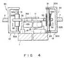
- Fig. 4 shows a system for supporting ϑ stage of the alignment stage device;
- Fig. 5 shows the support system attached;
- Fig. 6 is a sectional view taken along a line VI - VI in Fig. 5;
- Fig. 7 is an enlarged plan showing that portion of the support system which is encircled by a two-dot and dash line in Fig. 5;
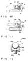
- Figs. 8 and 9 show a drive system for ϑ stage of the alignment stage device shown in Fig. 1;
- Figs. 10 and 11 show ϑ stage and the drive system combined;
- Fig. 12 is a sectional view showing a one point ball bearing which is a member for transmitting the drive force of the drive system to ϑ stage; and
- Fig. 13 is a block diagram showing an example of the control system for the alignment stage device shown in Fig. 1.
- Fig. 1 is a perspective view showing an example of the alignment stage device of the present invention dismantled. This alignment stage device can be used as a reticle stage for producing semiconductor elements and it may be applied to machine tools as well.
- As shown in Fig. 1, the alignment stage device has
base 1 made rectangular by a thick plate. Two support stands 2 and 2 are erected from the upper surface ofbase 1 on both sides thereof and opposed to each other to horizontallysupport y stage 5 which is a first stage made as a substantially square frame. Twoy stage guides 3 are formed along each of those opposed upper corners of support stands 2 and 2 to guidey stage 5 along axis of coordinate A. - This
y stage 5 is driven in the direction of axis y byreversible DC servomotor 4 fixed tobase 1. Rectangular rod-like drive slider 6 which is pressed from above against shaft 4a ofdrive motor 4 at a right angle is fixed toy stage 5 to drivey stage 5 in the direction of axis y. - As shown in Fig. 2,
friction drive slider 6 is pressed against shaft 4a by preload applied from the usual friction drive system to prevent shaft 4a from being slid and drivebar 6 from becoming unsteady and being back-rushed. More specifically, shaft 4a is pressed againstfriction drive slider 6 bypreloader 20 andfriction drive slider 6 is held between shaft 4a and back uproller 21. Therefore, the rotating motion of shaft 4a is changed to rectilinear motion by the friction drive system to rectilinearly drivefriction drive slider 6, so that y stage can be moved in the direction of axis y of a coordinate shown by A in Fig. 1. This movement ofy stage 5 can be detected by a y axis sensor (not shown) and the position ofy stage 5 can be feedback-controlled responsive to the result thus detected. - As shown in Fig. 1,
x stage 7 similar toy stage 5 and made by a square frame plate serving as a second stage is arranged in the center opening ofy stage 5. Fourguides 8 are located between x andy stages x stage 7 relative toy stage 5 in the direction of axis x.Friction drive slider 9 is extended outward fromx stage 7 and pressed against shaft 10a ofreversible DC servomotor 10, which is fixed toy stage 5, by a same friction drive system as shown in Fig. 2. This prevents shaft 10a from sliding relative tofriction drive slider 9, so thatx stage 7 can be moved in the direction of axis x of coordinate A when shaft 10a is rotated. The movement ofx stage 7 can be detected by an x axis sensor (not shown) and the position ofx stage 7 can be feedback-controlled according to the result thus detected. ϑ stage 11 which serves as a third stage is arranged in the center opening ofx stage 7. Thisϑ stage 11 has stands 11a, on which reticle (or mask) 14 is mounted, in the center thereof and each of thesestands 11a is provided with an opening 11b communicated with a vacuum source (not shown) to fixreticle 14 by vacuum suction. As will be described later,ϑ stage 11 is rotatably attached tox stage 7 through threeguides 13 and it is rotated in a small range round an axis perpendicular to the plane, on whichx stage 7 is positioned, by means ofDC servomotor 12 attached ontox stage 7.ϑ stage 11 can be rotated round axial lines parallel to axes x and y and also moved in the direction of axis z by means ofz stage 15 which serves as a fourth stage.- As shown in Figs. 1 and 3,
z stage 15 made by a thick plate as a square frame and arranged between support stands 2 and 2 onbase 1 and underϑ stage 11 can be moved up and down and tilted as well. Threesteel balls 15a freely rotatable at their certain positions are arranged on the upper surface ofz stage 15 andϑ stage 11 is supported onz stage 15 through thesesteel balls 15a. Steel balls 15a are contacted with both of ϑ andz stages z stage 15 toϑ stage 11.ϑ stage 11 is thus moved up and down and tilted relative tobase 1, following the movement ofz stage 15. Further,ϑ stage 11 can rotate on the upper surface ofz stage 15 through thesesteel balls 15a. Whenϑ stage 11 rotates relative toz stage 15,steel balls 15a serve as ball bearings and the rotation ofϑ stage 11 is not transmitted toz stage 15.- As shown in Fig. 1,
z stage 15 is supported by zstage drive systems 16, which are located at three apexes of a triangular onbase 1, in such a manner that it can be linearly moved in the direction of axis z or rotated round axial lines parallel to axes x and y or tilted relative tobase 1. Each ofdrive systems 16 includesreversible DC servomotor 17 fixed tobase 1 to drivez stage 15,slider 19 linearly movable on the upper surface ofbase 1 due to the rotation ofshaft 17b ofmotor 17,slope 18 formed onslider 19 andcam follower 15b attached toz stage 15 and contacted withslope 18. Zstage 15 is supported onbase 1 byslopes 18 onsliders 19 of zstage drive systems 16 andcam followers 15b. Zstage drive motor 17 is connected in this case toshaft 17b through harmonicdrive reduction system 17a, for example, to enableshaft 17b to receive reduced number of rotation frommotor 17.Drive motor 17 may be connected directly toshaft 17b. - A ball nut screw is formed round the outer circumference of
shaft 17b while a ball nut which can be screwed onto the ball nut screw is fixed toslider 19, so that the rotation ofdrive motor 17 can be changed to the rectilinear motion ofslider 19 due to these screw and nut. Threesliders 19 can be thus moved onbase 1 at the same time or independently of the others by drivemotor 17 through itsshaft 17b. According to the moving amount of each ofsliders 19,z stage 15 is moved in the direction of axis z, up and down in Figs. 1 and 3 or tilted, that is, rotated round axial lines parallel to axes x and y. Fig. 3 showsz stage 15 tilted relative tobase 1 to tilt ϑstage 11 throughsteel balls 15a. - As shown in Fig. 1 and Figs. 4 through 6, three arc portions 11c, each having the same radius of curvature and curved around the same point, are formed along the outer rim of ϑ stage (Fig. 6) to rotatably guide ϑ stage round an axial line perpendicular to that plane on which ϑ stage is positioned, and
ϑ stage 11 is supported at these arc portions 11c byx stage 7 through guides 13. According to the present invention, the curved portions 11c can have different radii of curvatures. - These guides 13 are located facing the center opening of
x stage 7 and each of guides 13 includes forkedbracket 30 fixed tox stage 7, strut 31 supported bybracket 30 at both ends thereof, and guidering 33 attached to strut 31 through ball bushing 32 in which a plurality ofballs 32a are freely rotatably housed, the outer circumference of this guide ring havingspherical face 33a when sectioned in the direction of its axial line. Thisguide ring 33 can freely rotateround strut 30 due to ball bushing 32 and also move alongstrut 30 in the direction of its axial line. - As apparent from ϑ
stage 11 kept horizontal in Fig. 4 and tilted in Fig. 5, ϑstage 11 is held by guide rings 33, keeping theirspherical faces 33a contacted with arc portions 11c of ϑstage 11. For the purpose of holding ϑ stage in this manner, each of opposedarms 30a ofbracket 30 is provided withslit 29 which is directed toward the center of ϑstage 11, and each end ofstruts 31 is inserted into thisslit 29. As shown in Fig. 7, strut 31 is urged in the longitudinal direction ofslit 29 or toward the center of ϑstage 11 by means of spring 28 whose one end is fixed to connectingsection 30b ofbracket 30. The direction in which strut 31 is urged by spring 28 is represented by arrow B in Figs. 5 and 6. - When guides 13 are arranged as shown in Fig. 6, ϑ stage is held by three
guides 13 at three arc portions 11c thereof.Struts 31 of stage guides 13 are urged toward the center of ϑ stage by means of springs 28 in this case. Therefore, guide rings 33 push arc portions 11c of ϑstage 11 toward the center of ϑstage 11. When ϑstage 11 rotates round an axial line perpendicular to that plane on whichϑ stage 11 is positioned, guide rings 33 hold ϑstage 11 while being rotated by friction force caused between theirspherical faces 33a and arc portions 11c of ϑstage 11. Further, the outer circumference of each of those guide rings 33 which urge arc portions 11c of ϑstage 11 is formed asspherical face 33a. Even when ϑstage 11 is moved along axis z or tilted relative tobase 1 by means of zstage drive systems 16, therefore, guide rings 33 can move along struts 31 in the direction of the axial line of each of thesestruts 31 due to theirball bushings 32 to thereby hold arc portions 11c of ϑstage 11 in them with uniform force. Whatever posture ϑ stage may be to take, therefore, stage guides 13 can follow the movement ofϑ stage 11 to reliably holdϑ stage 11 at an accurate position. - Although each of
struts 31 has been urged toward the center of ϑstage 11 by means of spring 28 in this example, it may be arranged instead of using springs 28 that each of guide rings 33 is made of rubber and that struts 31 are urged by the elasticity of these rubber-made guide rings 33. - As shown in Fig. 1, ϑ
stage 11 hasdrive slider 34 projected from the outer rim of ϑstage 11 and made as a rectangular plate. ϑstage 11 is rotated in a certain angular range round an axial line perpendicular to that plane, on whichϑ stage 11 is positioned, by means of ϑstage drive system 35 throughdrive slider 34. - As shown in detail in Figs. 8 through 11, ϑ
stage drive system 35 serves as a linear actuator comprisingfeed screw 37 horizontally positioned and connected to drivemotor 12 which is fixed to x stage (see Fig. 1), andnut member 38 screwed ontofeed screw 37. As shown in Figs. 10 and 11,guide rail 7a is fixed onto the upper surface ofx stage 7 along the axial line offeed screw 37 and cross roll table 38a (from which rollers are omitted in Figs. 10 and 11) which is guided byguide rail 7a is formed integral to that side ofnut member 38 which faces xstage 7. When drive motor 12 (see Fig. 1) is driven, therefore, feedscrew 37 is rotated.Nut member 38 screwed ontofeed screw 37 is thus guided byrail 7a to move in the axial direction offeed screw 37. Transmission system 36 which serves to transmit the movement ofnut member 38 in the axial direction offeed screw 37 to driveslider 34 includes a pair oftongue pieces nut member 38 towarddrive slider 34 orϑ stage 11, and pushmembers tongue pieces push members tongue piece 42 in the example shown in Figs. 8 and 9 is attached to the side oftongue piece 42 throughbelleville spring 46, for example, which has high rigidity, while the other 45 is attached directly totongue piece 43.- As shown in Fig. 12, the one point ball bearing which serves as
push member block 50 attached totongue piece nut member 38, large-diameter steel ball 47 freely rotatably seated on a plurality of small-diameter steel balls 48 in a recess of the fixing block and cover 49 for holding this large-diameter steel ball 47. Fixingblock 50 has athread 50a through which fixingblock 50 is attached to the tongue of the nut member, and cover 49 has center opening 49a through which a part of large-diameter steel ball 47 is exposed. That portion of large-diameter steel ball 47 which is exposed through the center opening 49a ofcover 49 can rotate on the side ofdrive slider 34 to serve aspush member tongue piece drive system 35 which serves as the linear actuator can be reliably transmitted to driveslider 34. - The front end portion of
drive slider 34 to whichtongue pieces drive slider 34 when ϑ stage is tilted relative to the base following the movement of z stage.Drive system 35 may use such appropriate means as the linear motor, hydraulic cylinder and piezo-element instead offeed screw 37 andnut member 38. - When feed screw 37 of
drive system 35 is rotated under such a state as shown in Fig. 8 by means of drive motor 12 (see Fig. 1),nut member 38 screwed ontofeed screw 37 is guided byrail 7a to move in the axial direction offeed screw 37. Pushmembers transmission system 36 attached tonut member 38 transmit drive force to driveslider 34 of ϑstage 11. - ϑ
stage 11 is held at its arc portions 11c by guides 13. Therefore, ϑstage 11 is rotated round an axial line perpendicular to that plane, on whichϑ stage 11 is positioned, only by angle C as shown in Fig. 9 due to drive force transmitted to driveslider 34, said angle C corresponding to the rotation amount offeed screw 37. Large-diameter steel balls 47 which serve as the push members rotate on both sides ofdrive slider 34 at this time. Therefore, friction force is hardly caused betweendrive slider 34 and driveforce transmission system 36 to thereby rotateϑ stage 11 smoothly. - Even when ϑ
stage 11 is tilted following the tilting of x stage 15 (see Fig. 1 and Figs. 3 through 5), large-diameter steel ball 47 ofpush member 44 rotates on the side ofdrive slider 34, as shown in Fig. 11, andϑ stage 11 is reliably held at a correct position by means ofguides 13, as shown in Fig. 5. ϑstage 11 is thus rotated with reliability. - According to the above-descrjbed alignment stage device shown in Fig. 1, the movement of
x stage 7 caused bydrive motor 10 through friction drive system andslider 9 and that ofz stage 15 caused bydrive motors 17 throughdrive systems 16 are transmitted directly to 0stage 11. The movement ofy stage 5 caused bydrive motor 4 through friction drive system andslider 6 is transmitted to ϑstage 11 throughx stage 7. Further, ϑstage 11 itself can be rotated relative tox stage 7 and round an axial line perpendicular to that plane, on whichϑ stage 11 is positioned, by means ofdrive motor 12 throughdrive system 35 and driveslider 34. ϑstage 11 can thus achieve six motions including three linear movements in those directions parallel to axes x, y and z and three rotary movements round those axial lines parallel to axes x, y and z. - In the case of the above-described alignment stage device, x, y and
ϑ stages stages stages stages z stage 15 for supportingϑ stage 11 is located under that plane on which x, y andϑ stages stage 11 can thus follow the movement ofz stage 15 directly to enhance its control precision. Furthermore, ϑstage 11 is supported bybase 1 throughz stage 15. Even when any error is caused in those movements of x andy stages stage 11. - Fig. 13 shows an example of the control system for the above-described alignment stage device.
- In the case of this control system,
main controller 55 is a microprocessor of 32 bits, which exchanges with parallel 1/0 (54) through a main bus information relating to the position and posture of ϑstage 11. Thismain controller 55 further exchanges with x andy stages controller 56,z stage controller 59 andϑ stage controller 63 through the main bus information relating to positions and postures of x, y, z and ϑ stages. - X and
y stages controller 56 has four A/D converters. When it receives control information frommain controller 55 on the basis of information inputted from parallel 1/0 (54), x andy stages controller 56 calculates how positions of x and y stages change from their reference ones, and compares the control information received with values calculated to send a control signal toservoamplifier 57. X and/or ystage drive motor 10 and/or 4 which is DC servomotor is made operative responsive to the control signal amplified byservoamplifier 57. When x and/or y stagefriction drive slider 9 and/or 6 is moved by the friction drive system, x and/ory stage 7 and/or 5 is moved accordingly. This moving amount of x and/ory stage 7 and/or 5 is detected bylinear scale 58 and the value detected is sent to A/D converter of x andy stages controller 56. This process is repeated until x and/ory stage 7 and/or 5 comes to its predetermined position. Z stage controller 59 calculates rotation amounts needed for three zstage drive motors 17 on the basis of control signals applied frommain controller 55 and sends control signals to servoamplifiers 60 on the basis of results thus calculated.Servoamplifiers 60 amplify the control signals applied fromz stage controller 59 and send them tomotors 17. The rotation of each ofmotors 17 is reduced byreduction system 17a andz stage 15 is moved in the direction of axis z or rotated round axial lines parallel to axes x and y responsive to the rotation amount of each of threemotors 17.Z stage 15 thus takes such position and posture as correspond to the rotation amount of each of threemotors 17. The rotation amount of each of threemotors 17 is detected byrotary encoder 61. The amounts thus detected are fed back to servoamplifiers 60 through F/V converters 62 and further sent toz stage controller 59. This process is repeated untilz stage 15 takes its position and posture needed.- ϑ
stage controller 63 calculates the rotation amount needed for ϑstage drive motor 12 responsive to instruction applied frommain controller 55 and sends a control signal toservoamplifier 64 on the basis of the result thus calculated.Servoamplifier 64 amplifies the control signal and supplies the thus-amplified signal to ϑstage drive motor 12.Feed screw 37 is rotated bymotor 12 andϑ stage 11 is thus rotated. The rotation amount of thisdrive motor 12 is detected byrotary encoder 65. The amount thus detected is fed back toservoamplifier 64 through F/V converter 66 and further sent to ϑstage controller 63. This process is repeated until ϑstage 15 takes its position needed. - X and
y stages controller 56,z stage controller 59 andϑ stage controller 63 have servo-lock and moving modes. These controllers hold x, y and ϑ stages at their set positions under servo-lock mode, while x, y and ϑ stages are moved under moving mode to those positions which are calculated on the basis of control information applied from the main controller.
Claims (14)
- An alignment stage device for precisely aligning a workpiece (14) comprising a base (1), a first stage (5) supported horizontally above the base (1) and movable along a first axis (y) in the horizontal plane, a second stage (7) supported by the first stage (5) and movable along an second axis (x) also in the horizontal plane and perpendicular to said first axis (y), and a third stage (11) having stands (11a) for supporting the workpiece (14), said third stage being mounted and guided relative to the second stage (7) and being rotatable around an axis perpendicular to the plane in which the third stage (11) is positioned, wherein said second and third stages (7,11) are mounted to said first stage such that they are moved along the first axis when the first stage (5) is moved, and said third stage (11) is mounted to said second stage such that it is moved along the second axis (x) when the second stage (7) is moved, said first and second stages (5,7) being square frames each having a center opening, said second stage (7) being arranged in the center opening of the first stage(5) and said third stage (11) being arranged in the center opening of said second stage (7) such that it can be guided and inclined by the second stage (7), the alignment stage device further comprising a fourth stage (15), for supporting said third stage (11) above said base (1), said fourth stage being supported by driving means (16) on the base (1) such that it can be inclined relative to the base (1) and/or moved along a third axis (z) perpendicular to the first and second axis (x,y), with said third stage (11) moving as the fourth stage (15) moves.
- The alignment stage device according to claim 1, characterized in that said means for causing the third stage (11) to follow the movement of the fourth stage (15) includes at least three small-diameter steel balls (15a) located between the underside of the third stage (11) and the top of the fourth stage (15).
- The alignment stage device according to claim 1 or 3, characterized in that said means (16) include drive motors (17) located at three positions on the base (1) and around the fourth stage (15), sliders (19) slid on the upper surface of the base by the drive motors, slopes (18) formed on the sliders and tilted relative to the upper surface of the base, and cam followers (15b) attached to the fourth stage and following the slopes (18) to move in the direction of the third axis line.
- The alignment stage device according to any one of claims 1 to 3, characterized in that the first, second and third stages (5, 7, 11) are arranged on a same plane and the fourth stage (15) is located between the third stage and the base (1).
- The alignment stage device according to any one of claims 1 to 3, characterized in that the third stage (11) has arc portions (11c), curved around the same point, at at least three positions along its outer rim and said device further including guide means (13) fixed to the second stage (7) to correspond to the arc portions (11c) of the third stage (11) and hold the third stage in such a way that the third stage can be tilted relative to the second stage (7) and rotated round an axis line perpendicular to that plane on which the third stage is positioned.
- The alignment stage device according to claim 5, characterized in that the guide means (13) includes a bracket (30) fixed to the second stage (7), a strut (31) supported by the bracket, and a guide ring (33) freely slidably and rotatably attached to the strut through a ball bushing (32) and contacted with the arc portion (11c) of the third stage (11).
- The alignment stage device according to claim 6, characterized in that said guide ring (33) has an outer spherical circumference.
- The alignment stage device according to claim 7, characterized in that at least one of the guide means (13) pushes the arc portion (11c) toward the center of the third stage (11) through the guide ring (33).
- The alignment stage device according to claim 8, characterized in that at least one of the guide means (13) includes a forked bracket (30) having two arms (30a) and a section (30b) for connecting these arms with each other, a slit (29) formed in each of the arms and directed in the radial direction of the third stage to guide the end of the strut, and springs (28) for urging the strut (31) along the slit in the center direction of the third stage.
- The alignment stage device according to any one of claims 1 to 9, further comprising a plate-like drive slider (34) fixed to the third stage (11), and a drive means (35) fixed to the second stage (7) and serving to rotate the third stage round an axis line perpendicular to that plane, on which the third stage is positioned, through the drive slider (34).
- The alignment stage device according to claim 10, characterized in that said drive means (35) is a linear actuator comprising a drive motor (12) fixed to the second stage (7), a feed screw rotated by the drive motor, and a nut member (38) screwed onto the feed screw.
- The alignment stage device according to claim 11, further comprising a means (36) for transmitting the drive force of the linear actuator (35) to the drive slider (34) of the third stage.
- The alignment stage device according to claim 12, characterized in that said means (36) includes tongue pieces (42, 43) projected from both ends of the nut member (38), and push members (44, 45) fixed to that sides of these tongue pieces which are opposed to each other.
- The alignment stage device according to claim 13, characterized in that each of the push members (44, 45) is a one point ball bearing having a steel ball (47) freely rotatable on one side of the drive slider (34) and at least one of the push members is urged against the other.
Applications Claiming Priority (6)
| Application Number | Priority Date | Filing Date | Title |
|---|---|---|---|
| JP63026790AJPH01202687A (en) | 1988-02-08 | 1988-02-08 | positioning device |
| JP26790/88 | 1988-02-08 | ||
| JP63030405AJPH01206287A (en) | 1988-02-12 | 1988-02-12 | positioning device |
| JP30405/88 | 1988-02-12 | ||
| JP132994/88 | 1988-05-31 | ||
| JP63132994AJPH01302197A (en) | 1988-05-31 | 1988-05-31 | positioning device |
Publications (3)
| Publication Number | Publication Date |
|---|---|
| EP0327949A2 EP0327949A2 (en) | 1989-08-16 |
| EP0327949A3 EP0327949A3 (en) | 1990-10-17 |
| EP0327949B1true EP0327949B1 (en) | 1993-12-15 |
Family
ID=27285539
Family Applications (1)
| Application Number | Title | Priority Date | Filing Date |
|---|---|---|---|
| EP89101756AExpired - LifetimeEP0327949B1 (en) | 1988-02-08 | 1989-02-01 | Alignment stage device |
Country Status (4)
| Country | Link |
|---|---|
| US (1) | US4948330A (en) |
| EP (1) | EP0327949B1 (en) |
| KR (1) | KR930000292B1 (en) |
| DE (1) | DE68911330T2 (en) |
Families Citing this family (39)
| Publication number | Priority date | Publication date | Assignee | Title |
|---|---|---|---|---|
| JP2960423B2 (en)* | 1988-11-16 | 1999-10-06 | 株式会社日立製作所 | Sample moving device and semiconductor manufacturing device |
| JPH03159148A (en)* | 1989-11-16 | 1991-07-09 | Advantest Corp | Positioning device and ic test device using the positioning device |
| US5061039A (en)* | 1990-06-22 | 1991-10-29 | The United States Of America As Represented By The United States Department Of Energy | Dual axis translation apparatus and system for translating an optical beam and related method |
| US5165297A (en)* | 1991-02-15 | 1992-11-24 | Albert Einstein College Of Medicine Of Yeshiva University, A Div. Of Yeshiva Univ. | Remote controlled micromanipulator |
| US5303035A (en)* | 1992-05-04 | 1994-04-12 | New Focus, Inc. | Precision micropositioner |
| JPH07218749A (en)* | 1993-12-07 | 1995-08-18 | Furukawa Electric Co Ltd:The | Multi-axis fine movement stage |
| DE69500707T2 (en)* | 1994-02-07 | 1998-02-12 | Ushiodenki K.K., Tokio/Tokyo | Holding device |
| US5528118A (en)* | 1994-04-01 | 1996-06-18 | Nikon Precision, Inc. | Guideless stage with isolated reaction stage |
| US6989647B1 (en)* | 1994-04-01 | 2006-01-24 | Nikon Corporation | Positioning device having dynamically isolated frame, and lithographic device provided with such a positioning device |
| US5874820A (en)* | 1995-04-04 | 1999-02-23 | Nikon Corporation | Window frame-guided stage mechanism |
| US7365513B1 (en) | 1994-04-01 | 2008-04-29 | Nikon Corporation | Positioning device having dynamically isolated frame, and lithographic device provided with such a positioning device |
| US5489089A (en)* | 1994-04-26 | 1996-02-06 | Ohio Northern University | Automatic alignmant vise |
| JPH08241126A (en)* | 1995-03-02 | 1996-09-17 | Canon Inc | Synchronous position control method and apparatus |
| US6008500A (en)* | 1995-04-04 | 1999-12-28 | Nikon Corporation | Exposure apparatus having dynamically isolated reaction frame |
| NL1000815C2 (en)* | 1995-07-14 | 1997-01-15 | Univ Delft Tech | XY displacement device. |
| JP3365598B2 (en)* | 1995-08-31 | 2003-01-14 | 富士通株式会社 | Method and apparatus for manufacturing optical module assembly |
| CH691709A5 (en)* | 1995-11-03 | 2001-09-14 | Zeiss Carl Fa | Drive for moving a moving part of the device. |
| IL119213A (en)* | 1996-09-06 | 2000-08-31 | Orbot Instr Ltd | Universal chuck for holding plates of various sizes |
| US5812310A (en)* | 1996-10-16 | 1998-09-22 | Applied Precision, Inc. | Orthogonal high accuracy microscope stage |
| KR100235610B1 (en)* | 1997-06-30 | 1999-12-15 | Daewoo Electronics Co Ltd | Panel positioning device |
| US6185030B1 (en)* | 1998-03-20 | 2001-02-06 | James W. Overbeck | Wide field of view and high speed scanning microscopy |
| US6764272B1 (en)* | 1999-05-27 | 2004-07-20 | Micron Technology, Inc. | Adjustable coarse alignment tooling for packaged semiconductor devices |
| US6405659B1 (en) | 2000-05-01 | 2002-06-18 | Nikon Corporation | Monolithic stage |
| JP2001328043A (en)* | 2000-05-24 | 2001-11-27 | Harmonic Drive Syst Ind Co Ltd | Table positioning device |
| US6553644B2 (en)* | 2001-02-09 | 2003-04-29 | International Business Machines Corporation | Fixture, carrier ring, and method for processing delicate workpieces |
| KR100416791B1 (en)* | 2001-03-19 | 2004-01-31 | 삼성전자주식회사 | Microscope Apparatus and Inspection Method for Semiconductor Wafer Inspection |
| DE10139586C2 (en)* | 2001-08-11 | 2003-11-27 | Erich Thallner | Plate-shaped adjustment element |
| US6888289B2 (en)* | 2002-07-16 | 2005-05-03 | Baldor Electric Company | Multi-axes, sub-micron positioner |
| US7036777B2 (en)* | 2003-05-14 | 2006-05-02 | Quickset International, Inc. | Zero backlash positioning device |
| US7180662B2 (en)* | 2004-04-12 | 2007-02-20 | Applied Scientific Instrumentation Inc. | Stage assembly and method for optical microscope including Z-axis stage and piezoelectric actuator for rectilinear translation of Z stage |
| KR100610833B1 (en) | 2004-06-21 | 2006-08-08 | 현대자동차주식회사 | Component Positioning Device |
| KR101130890B1 (en) | 2005-03-18 | 2012-03-28 | 엘지전자 주식회사 | Proximity Exposure Type Exposure System |
| DE102005045680A1 (en)* | 2005-09-24 | 2007-04-05 | Edmund Uschkurat | Device for aligning an object along an X-, Y- or Z-axis used e.g. in the pharmaceutical industry comprises a base plate and tables adjustable along the X-axis, Y-axis and the Z-axis |
| FR2893132B1 (en)* | 2005-11-09 | 2008-07-25 | Innopsys Sa | SCALING ANALYSIS DEVICE FOR FLUORESCENCE BIOLOGICAL SAMPLES |
| JP4849227B2 (en)* | 2006-07-31 | 2012-01-11 | 株式会社ダイフク | Automatic load position correction device |
| CN102910405B (en)* | 2012-10-25 | 2015-12-09 | 深圳市华星光电技术有限公司 | A kind of card casket transportation fork-truck |
| US10041973B2 (en)* | 2013-09-04 | 2018-08-07 | Infineon Technologies Ag | Method and apparatus for dynamic alignment of semiconductor devices |
| US10186450B2 (en)* | 2014-07-21 | 2019-01-22 | Asm Ip Holding B.V. | Apparatus and method for adjusting a pedestal assembly for a reactor |
| JP6960352B2 (en)* | 2018-02-20 | 2021-11-05 | 株式会社日立ハイテク | Stage device and charged particle beam device |
Family Cites Families (17)
| Publication number | Priority date | Publication date | Assignee | Title |
|---|---|---|---|---|
| GB892836A (en)* | 1958-09-25 | 1962-03-28 | Leitz Ernst Gmbh | Improvements in or relating to arrangements for effecting fine adjusting movement of microscope stages and other movable members requiring precision adjustment |
| GB1193501A (en)* | 1967-02-02 | 1970-06-03 | Watson W & Sons Ltd | Improvements in or relating to Positioning Apparatus |
| US3466514A (en)* | 1967-06-26 | 1969-09-09 | Ibm | Method and apparatus for positioning objects in preselected orientations |
| GB1270566A (en)* | 1969-10-31 | 1972-04-12 | Image Analysing Computers Ltd | Improved precision stage for optical microscope |
| GB1301008A (en)* | 1970-08-04 | 1972-12-29 | Ass Elect Ind | Improvements in or relating to specimen stages for electron microscopes |
| US3829978A (en)* | 1972-09-18 | 1974-08-20 | U Okun | Worktable for positioning workpieces in measuring devices to check dimensions |
| US3918167A (en)* | 1974-03-01 | 1975-11-11 | Gerber Scientific Instr Co | Apparatus for sensing relative movement of a work table and tool |
| US4328553A (en)* | 1976-12-07 | 1982-05-04 | Computervision Corporation | Method and apparatus for targetless wafer alignment |
| JPS5650517Y2 (en)* | 1977-02-09 | 1981-11-26 | ||
| US4248498A (en)* | 1978-06-29 | 1981-02-03 | Georges Michael P | Automatic microscope slide |
| JPS5878642A (en)* | 1981-11-05 | 1983-05-12 | 株式会社ニコン | Fundus camera focusing position detection device |
| US4457664A (en)* | 1982-03-22 | 1984-07-03 | Ade Corporation | Wafer alignment station |
| US4609264A (en)* | 1984-01-23 | 1986-09-02 | The Micromanipulator Microscope Company, Inc. | Apparatus for positioning flat objects for microscopic examination |
| US4667415A (en)* | 1985-11-29 | 1987-05-26 | Gca Corporation | Microlithographic reticle positioning system |
| JPS6325946A (en)* | 1986-07-18 | 1988-02-03 | Toshiba Corp | Fine movement table device |
| JPS6372138A (en)* | 1986-09-12 | 1988-04-01 | Metsukusu:Kk | Device for positioning silicon wafer |
| JPH052632A (en)* | 1991-06-25 | 1993-01-08 | Sumitomo Heavy Ind Ltd | Deciding device for fruit surface pattern |
- 1989
- 1989-02-01EPEP89101756Apatent/EP0327949B1/ennot_activeExpired - Lifetime
- 1989-02-01DEDE68911330Tpatent/DE68911330T2/ennot_activeExpired - Fee Related
- 1989-02-03USUS07/305,761patent/US4948330A/ennot_activeExpired - Fee Related
- 1989-02-08KRKR1019890001407Apatent/KR930000292B1/ennot_activeExpired - Fee Related
Also Published As
| Publication number | Publication date |
|---|---|
| DE68911330D1 (en) | 1994-01-27 |
| KR930000292B1 (en) | 1993-01-15 |
| EP0327949A2 (en) | 1989-08-16 |
| US4948330A (en) | 1990-08-14 |
| EP0327949A3 (en) | 1990-10-17 |
| KR890013710A (en) | 1989-09-25 |
| DE68911330T2 (en) | 1994-05-26 |
Similar Documents
| Publication | Publication Date | Title |
|---|---|---|
| EP0327949B1 (en) | Alignment stage device | |
| EP0611062B1 (en) | Electromagnetic alignment apparatus | |
| JP4560235B2 (en) | Angle adjustment table device | |
| US5760564A (en) | Dual guide beam stage mechanism with yaw control | |
| US8104752B2 (en) | Integrated large XY rotary positioning table with virtual center of rotation | |
| US4676649A (en) | Multi-axis gas bearing stage assembly | |
| JP4656334B2 (en) | Alignment device | |
| KR102080447B1 (en) | Kinematic holding system for a placement head of a placement apparatus | |
| JPH0134746B2 (en) | ||
| EP0525872B1 (en) | Positioning device having two manipulators operating in parallel, and optical lithographic device provided with such a positioning device | |
| US6257957B1 (en) | Tactile feedback system | |
| JPH029550A (en) | Drive device for 6 degrees of freedom fine movement stage | |
| JPS62152632A (en) | table equipment | |
| JPH05202934A (en) | Bearing and machine with it | |
| JP3458329B2 (en) | Mask stage drive mechanism and control method thereof | |
| JP2803880B2 (en) | Cartesian robot | |
| JP3388498B2 (en) | Machine Tools | |
| KR102444433B1 (en) | Boring apparatus for repairing reactor lower head | |
| JPH04322982A (en) | Cartesian robot | |
| JPS6122740Y2 (en) | ||
| JPH04261789A (en) | Parts transfer device | |
| KR950011166B1 (en) | Poerating system of double structure reticle for reduction projecting exposure apparatus | |
| JP2711898B2 (en) | Non-contact guide type positioning table | |
| JPH04361194A (en) | Correcting method for position of x, y, z axis table taking deflection into consideration | |
| JP2019139074A (en) | Stage device |
Legal Events
| Date | Code | Title | Description |
|---|---|---|---|
| PUAI | Public reference made under article 153(3) epc to a published international application that has entered the european phase | Free format text:ORIGINAL CODE: 0009012 | |
| 17P | Request for examination filed | Effective date:19890224 | |
| AK | Designated contracting states | Kind code of ref document:A2 Designated state(s):DE FR GB NL | |
| PUAL | Search report despatched | Free format text:ORIGINAL CODE: 0009013 | |
| AK | Designated contracting states | Kind code of ref document:A3 Designated state(s):DE FR GB NL | |
| 17Q | First examination report despatched | Effective date:19920615 | |
| GRAA | (expected) grant | Free format text:ORIGINAL CODE: 0009210 | |
| AK | Designated contracting states | Kind code of ref document:B1 Designated state(s):DE FR GB NL | |
| REF | Corresponds to: | Ref document number:68911330 Country of ref document:DE Date of ref document:19940127 | |
| ET | Fr: translation filed | ||
| PLBE | No opposition filed within time limit | Free format text:ORIGINAL CODE: 0009261 | |
| STAA | Information on the status of an ep patent application or granted ep patent | Free format text:STATUS: NO OPPOSITION FILED WITHIN TIME LIMIT | |
| 26N | No opposition filed | ||
| PGFP | Annual fee paid to national office [announced via postgrant information from national office to epo] | Ref country code:GB Payment date:19960123 Year of fee payment:8 | |
| PGFP | Annual fee paid to national office [announced via postgrant information from national office to epo] | Ref country code:FR Payment date:19960125 Year of fee payment:8 | |
| PGFP | Annual fee paid to national office [announced via postgrant information from national office to epo] | Ref country code:NL Payment date:19960229 Year of fee payment:8 | |
| PG25 | Lapsed in a contracting state [announced via postgrant information from national office to epo] | Ref country code:GB Effective date:19970201 | |
| PGFP | Annual fee paid to national office [announced via postgrant information from national office to epo] | Ref country code:DE Payment date:19970207 Year of fee payment:9 | |
| PG25 | Lapsed in a contracting state [announced via postgrant information from national office to epo] | Ref country code:NL Effective date:19970901 | |
| GBPC | Gb: european patent ceased through non-payment of renewal fee | Effective date:19970201 | |
| PG25 | Lapsed in a contracting state [announced via postgrant information from national office to epo] | Ref country code:FR Effective date:19971030 | |
| NLV4 | Nl: lapsed or anulled due to non-payment of the annual fee | Effective date:19970901 | |
| REG | Reference to a national code | Ref country code:FR Ref legal event code:ST | |
| PG25 | Lapsed in a contracting state [announced via postgrant information from national office to epo] | Ref country code:DE Free format text:LAPSE BECAUSE OF NON-PAYMENT OF DUE FEES Effective date:19981103 |