EP0327499A1 - Measuring head - Google Patents
Measuring headDownload PDFInfo
- Publication number
- EP0327499A1 EP0327499A1EP89810061AEP89810061AEP0327499A1EP 0327499 A1EP0327499 A1EP 0327499A1EP 89810061 AEP89810061 AEP 89810061AEP 89810061 AEP89810061 AEP 89810061AEP 0327499 A1EP0327499 A1EP 0327499A1
- Authority
- EP
- European Patent Office
- Prior art keywords
- measuring
- mirror
- measuring head
- optics
- axis
- Prior art date
- Legal status (The legal status is an assumption and is not a legal conclusion. Google has not performed a legal analysis and makes no representation as to the accuracy of the status listed.)
- Granted
Links
- 239000011521glassSubstances0.000claimsabstractdescription32
- 210000003128headAnatomy0.000claimsdescription41
- 210000001747pupilAnatomy0.000claimsdescription12
- 238000005286illuminationMethods0.000abstractdescription8
- 238000005259measurementMethods0.000description13
- 230000003287optical effectEffects0.000description13
- 230000003595spectral effectEffects0.000description7
- 238000001228spectrumMethods0.000description6
- 230000008878couplingEffects0.000description5
- 238000010168coupling processMethods0.000description5
- 238000005859coupling reactionMethods0.000description5
- 239000000463materialSubstances0.000description4
- 238000000354decomposition reactionMethods0.000description3
- 238000012545processingMethods0.000description3
- 230000005855radiationEffects0.000description3
- 238000011156evaluationMethods0.000description2
- 238000003384imaging methodMethods0.000description2
- 238000000034methodMethods0.000description2
- 238000010183spectrum analysisMethods0.000description2
- 229910052724xenonInorganic materials0.000description2
- FHNFHKCVQCLJFQ-UHFFFAOYSA-Nxenon atomChemical compound[Xe]FHNFHKCVQCLJFQ-UHFFFAOYSA-N0.000description2
- 230000004075alterationEffects0.000description1
- 238000006243chemical reactionMethods0.000description1
- 239000011248coating agentSubstances0.000description1
- 238000000576coating methodMethods0.000description1
- 238000000205computational methodMethods0.000description1
- 238000010276constructionMethods0.000description1
- 238000001739density measurementMethods0.000description1
- 230000001419dependent effectEffects0.000description1
- 238000013461designMethods0.000description1
- 238000011161developmentMethods0.000description1
- 230000018109developmental processEffects0.000description1
- 238000010586diagramMethods0.000description1
- 230000005670electromagnetic radiationEffects0.000description1
- 239000004973liquid crystal related substanceSubstances0.000description1
- 238000012544monitoring processMethods0.000description1
- 238000003825pressingMethods0.000description1
- 238000000985reflectance spectrumMethods0.000description1
- 239000007787solidSubstances0.000description1
- 230000001960triggered effectEffects0.000description1
Images


Classifications
- G—PHYSICS
- G01—MEASURING; TESTING
- G01J—MEASUREMENT OF INTENSITY, VELOCITY, SPECTRAL CONTENT, POLARISATION, PHASE OR PULSE CHARACTERISTICS OF INFRARED, VISIBLE OR ULTRAVIOLET LIGHT; COLORIMETRY; RADIATION PYROMETRY
- G01J3/00—Spectrometry; Spectrophotometry; Monochromators; Measuring colours
- G01J3/02—Details
- G01J3/0205—Optical elements not provided otherwise, e.g. optical manifolds, diffusers, windows
- G01J3/0208—Optical elements not provided otherwise, e.g. optical manifolds, diffusers, windows using focussing or collimating elements, e.g. lenses or mirrors; performing aberration correction
- G—PHYSICS
- G01—MEASURING; TESTING
- G01J—MEASUREMENT OF INTENSITY, VELOCITY, SPECTRAL CONTENT, POLARISATION, PHASE OR PULSE CHARACTERISTICS OF INFRARED, VISIBLE OR ULTRAVIOLET LIGHT; COLORIMETRY; RADIATION PYROMETRY
- G01J3/00—Spectrometry; Spectrophotometry; Monochromators; Measuring colours
- G01J3/02—Details
- G01J3/0205—Optical elements not provided otherwise, e.g. optical manifolds, diffusers, windows
- G01J3/021—Optical elements not provided otherwise, e.g. optical manifolds, diffusers, windows using plane or convex mirrors, parallel phase plates, or particular reflectors
- G—PHYSICS
- G01—MEASURING; TESTING
- G01J—MEASUREMENT OF INTENSITY, VELOCITY, SPECTRAL CONTENT, POLARISATION, PHASE OR PULSE CHARACTERISTICS OF INFRARED, VISIBLE OR ULTRAVIOLET LIGHT; COLORIMETRY; RADIATION PYROMETRY
- G01J3/00—Spectrometry; Spectrophotometry; Monochromators; Measuring colours
- G01J3/02—Details
- G01J3/0297—Constructional arrangements for removing other types of optical noise or for performing calibration
- G—PHYSICS
- G01—MEASURING; TESTING
- G01N—INVESTIGATING OR ANALYSING MATERIALS BY DETERMINING THEIR CHEMICAL OR PHYSICAL PROPERTIES
- G01N21/00—Investigating or analysing materials by the use of optical means, i.e. using sub-millimetre waves, infrared, visible or ultraviolet light
- G01N21/17—Systems in which incident light is modified in accordance with the properties of the material investigated
- G01N21/47—Scattering, i.e. diffuse reflection
- G01N21/4738—Diffuse reflection, e.g. also for testing fluids, fibrous materials
- G01N21/474—Details of optical heads therefor, e.g. using optical fibres
- G—PHYSICS
- G02—OPTICS
- G02B—OPTICAL ELEMENTS, SYSTEMS OR APPARATUS
- G02B19/00—Condensers, e.g. light collectors or similar non-imaging optics
- G02B19/0004—Condensers, e.g. light collectors or similar non-imaging optics characterised by the optical means employed
- G02B19/0028—Condensers, e.g. light collectors or similar non-imaging optics characterised by the optical means employed refractive and reflective surfaces, e.g. non-imaging catadioptric systems
- G—PHYSICS
- G02—OPTICS
- G02B—OPTICAL ELEMENTS, SYSTEMS OR APPARATUS
- G02B19/00—Condensers, e.g. light collectors or similar non-imaging optics
- G02B19/0033—Condensers, e.g. light collectors or similar non-imaging optics characterised by the use
- G02B19/0085—Condensers, e.g. light collectors or similar non-imaging optics characterised by the use for use with both a detector and a source
- G—PHYSICS
- G01—MEASURING; TESTING
- G01J—MEASUREMENT OF INTENSITY, VELOCITY, SPECTRAL CONTENT, POLARISATION, PHASE OR PULSE CHARACTERISTICS OF INFRARED, VISIBLE OR ULTRAVIOLET LIGHT; COLORIMETRY; RADIATION PYROMETRY
- G01J3/00—Spectrometry; Spectrophotometry; Monochromators; Measuring colours
- G01J3/12—Generating the spectrum; Monochromators
- G01J3/18—Generating the spectrum; Monochromators using diffraction elements, e.g. grating
- G01J3/1838—Holographic gratings
- G—PHYSICS
- G01—MEASURING; TESTING
- G01N—INVESTIGATING OR ANALYSING MATERIALS BY DETERMINING THEIR CHEMICAL OR PHYSICAL PROPERTIES
- G01N21/00—Investigating or analysing materials by the use of optical means, i.e. using sub-millimetre waves, infrared, visible or ultraviolet light
- G01N21/17—Systems in which incident light is modified in accordance with the properties of the material investigated
- G01N21/47—Scattering, i.e. diffuse reflection
- G01N21/4738—Diffuse reflection, e.g. also for testing fluids, fibrous materials
- G01N21/474—Details of optical heads therefor, e.g. using optical fibres
- G01N2021/4752—Geometry
- G01N2021/4757—Geometry 0/45° or 45/0°
- G—PHYSICS
- G01—MEASURING; TESTING
- G01N—INVESTIGATING OR ANALYSING MATERIALS BY DETERMINING THEIR CHEMICAL OR PHYSICAL PROPERTIES
- G01N2201/00—Features of devices classified in G01N21/00
- G01N2201/08—Optical fibres; light guides
- G01N2201/0806—Light rod
Definitions
- the inventionrelates to a measuring head according to the preamble of claim 1 and the preamble of subsidiary claim 3.
- Such a measuring head with projection optics for illuminating a measuring surface and with measuring optics for the remitted measuring lightis known from US-A-4 078 858 and has an incandescent lamp which is assigned a collimator lens and a deflecting mirror and a further collecting lens for generating a measuring spot are.
- the light remitted by the measuring spot at 45 °reaches the measuring optics, which have the spherical ring mirror and the flat ring-shaped mirror.
- US-A-3 982 824teaches a mirror system for electromagnetic radiation or acoustic radiation in which a primary mirror and a secondary mirror cooperate to avoid shadowing and achromatic aberration.
- the mirror surfaces of the primary mirrorare formed by a parabola section rotating around the optical axis as generatrix, the parabola focal point describes a circular focal line in a radial plane to the optical axis of the mirror system.
- the mirror surface of the secondary mirror of the mirror systemis formed by rotating part of an ellipse around the system axis, one focal point of the ellipse remaining on the optical axis, while the second focal point of the ellipse moves in a circular focal line around the optical axis of the mirror system when the Ellipse rotates.
- a reflector arrangement for concentrating the radiation emanating from a rod-shaped flash lamp onto a rod made of a laser material and running parallel to the flash lampis described in GB-A 281 265.
- the reflector arrangement of the optically pumped laseris designed as a cylinder aligned parallel to the longitudinal axes of the flash lamp and the laser rod, which essentially has the shape of an ellipse in cross section, the focal points or focal lines of which run on the one hand through the flash lamp and on the other hand through the laser rod.
- the Cross-section of the elliptical cylindrical reflector in the area of the two main apicesspecially shaped to collect the light emitted in a normal elliptical mirror in a blind spot and to reflect it at the intersection of the minor axis of the ellipse with the mirror surface or to collect it from there.
- the cross-sectional shape of this cylindrical reflectoris thus created by superimposing a main ellipse with four secondary ellipses, the ellipse surfaces all lying in the same plane.
- a device for detecting the optical density of photographswhich is described in US Pat. No. 3,244,062, has a measuring head with projection optics which images the light of an incandescent lamp onto the photographic material and with measuring optics which do so decouples essentially vertically scattered light back from the photographic surface via a deflecting mirror transverse to the optical axis of the projection optics and acts on the input slit of a photoelectron multiplier with the aid of a lens.
- the projection opticsallow the light from the incandescent lamp in the measuring head to be applied to the measuring spot on all sides at an angle of incidence of essentially 45 °.
- the projection optics assigned to the incandescent lampcontain a spherical ring mirror which surrounds the incandescent lamp, the filament of the incandescent lamp extending along the optical axis of the spherical ring mirror. That of the spheri
- the ring mirror's outgoing lamp light parallel to the optical axis of the projection opticsis focused on the measuring surface with the aid of a simple annular mirror.
- the quality of the projection optics and the measurement optics of the known deviceis sufficient for simple density measurements when determining optical reflectance properties.
- a portable reflectometeris known from FR-A-1 527 717, which has a measuring head with an incandescent lamp and projection optics and a measuring optic.
- the light of the incandescent lampacts on a filter directly on the one hand on a first photoresistor and on the other hand on the projection optics and the measuring optics a second photoresistor.
- the two photoresistorsare arranged in an adjustable bridge circuit, with the aid of which the intensity of the light reflected from a measuring surface can be evaluated.
- the filament of the light bulb in the measuring headis at the focal point of a parabolic mirror which has a recess for the filter to be used in each case.
- the light leaving the parabolic mirror essentially in the direction of the optical axispasses via a conical optical waveguide or collector made of a refractive material to a coupling disc made of refractive material, the diameter of which is smaller than the diameter of the parabolic mirror and smaller than the opposite end of the conical collector.
- the coupling discis pressed firmly against the surface of the object to be examined, which is, in particular, food or agricultural products.
- the conical collectorhas a cylindrical bore in which there is a cylindrical glass rod.
- the glass rodOn the side facing the coupling plate, the glass rod has a flat end face which is glued to the coupling plate.
- the glass rodover a spherical surface, the associated focal point of which lies on the surface of the light-refractive coupling disc, which can be pressed onto the measuring surface to be examined.
- the second photoresistoris located within the hole in the conical collector at a distance from the spherical surface of the glass rod.
- the first photoresistorwhich detects the intensity of the output light, is located on the back of the photoresistor to which the measuring light is applied. Spectral analysis is not possible with the known portable reflectometer, but only an analysis of the reflectance using various interchangeable filters.
- the inventionhas for its object to provide a measuring head of the type mentioned, which allows the measuring light remitted from the measuring spot to be fed with sufficient precision and intensity to a grating monochromator in order to be able to carry out a spectral analysis of the remitted light .
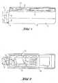
- the device shown partially cut away in FIG. 1corresponds in its outer dimensions to a hand-held densitometer and is therefore of a correspondingly compact design.
- the hand-held device shown in FIG. 1allows not only densitometric variables but also reflectance and density spectra and colorimetric variables to be recorded.
- the handheld devicehas a housing 1, in which one or more printed circuit boards 2, 3 are arranged for a measured value processing and control logic, which in the the upper part of the cut-open housing 1 is shown schematically.
- a measuring head 4protrudes from the left side wall of the housing 1 and can be moved parallel to the bottom 6 of the housing 1 between a rest position shown in solid lines in FIG. 1 and a working position shown in broken lines in FIG. 1 along the double arrow 5.
- a visor plate 7projects beyond the edge of the measuring head 4, which can be clearly seen in particular in FIG. 2.
- the sighting plate 7has a measuring aperture 8 which serves to indicate the position and size of a measuring spot 57 of the measuring head 4 in the working position and to shield stray light.
- the optically active axis of the measuring head 4runs exactly through the center of the measuring aperture 8.
- a filter wheel drive 9which is in engagement with a filter wheel provided in the measuring head 4 and allows a polarizer for measuring wet printed sheets, a D65 conversion filter, as desired, in the beam path of the measuring head 4 for the consideration of fluorescence or an aperture without filter.
- the filter wheel drive 9thus has three positions which can be set by hand, but can be shown on a display panel 10, for example a liquid crystal display.
- the display field 10also serves to display the measured values acquired with the hand-held device in numerical form or in the form of spectra or bar diagrams.
- a number of keys on a keyboard 11 and a plurality of information fields 12 assigned to the displays on the display field 10are provided around the display field 10.
- the display field 10, the keyboard and the information fields 12are located on the upper side 13 of the housing 1, a large-area measuring key 14 being provided on the side facing away from the measuring head 4 for triggering a measuring process.
- the measured value processing and control logicis caused to move the measuring head 4 from the rest position into the working position in order to use a spectral chamber provided in the interior of the housing 1 with a diffraction grating 55 shown in FIG. 5 to increase the spectrum of the light detect, which is remitted at the location of the measuring orifice 8, for example from a printed sheet on which the handheld device rests.
- the remission spectrumis processed with the aid of the measured value processing and control logic. After acquiring the spectrum, the measuring head 4 moves back into its rest position until a new measuring process is triggered by pressing the measuring key 14.
- the measuring head 4is moved with the aid of a measuring carriage, not shown in the drawing, which is guided so as to be longitudinally displaceable within the housing 1.
- the measuring head 4contains a measuring head optics which consists of the illuminating optics 115 shown in FIG. 3 and the measuring optics 116 shown in FIG. 5.
- 5also shows the diffraction grating 55, the holder of which is fastened to a rotatable grating shaft 30 in order to tune the spectral range to be detected by rotating the grating shaft 30.
- the measuring head optics housed in the measuring head 4have the task, on the one hand, of illuminating the measuring spot 57, which is illustrated by a line in FIGS. 3 and 5, and, on the other hand, of collecting the light remitted by the illuminated measuring spot 57 and for the spectral decomposition onto the diffraction grating 55 to throw.
- the lighting optics shown in Fig. 3allows the measuring spot 57 to be applied to all sides at an angle of incidence of essentially 45 ° ⁇ 5 ° with the light originating from an incandescent lamp 117, the measuring light reflected back from the measuring spot 57 into the measuring optics 116 under one Measuring angle of essentially 0 ° ⁇ 5 ° is received.
- the diameter of the measuring spot 57is 3 mm.
- the incandescent lamp light emitted by the incandescent lamp 117represents illumination with the type of light A, the incandescent lamp being designed in such a way that it provides the measuring light with the required color temperature.
- the incandescent lamp 117is arranged in the measuring head 4 so that its filament 118 is located on the longitudinal axis or axis of rotation 119 of the rotationally symmetrical illumination optics 115.
- the filament 118lies in a first ellipse focal point, which is assigned to an asphere 120, which is shown in FIG. 3 above the incandescent lamp 117 and is likewise constructed to be rotationally symmetrical.
- the asphereis 120 mirrored on the side facing the incandescent lamp 117 and has the shape shown enlarged in FIG. 4.
- the asphere 120On the mirrored side facing the incandescent lamp 117, the asphere 120 has an annular depression 121 which extends around the axis of rotation 119 and whose inner edge forms a central elevation 122 which lies on the axis of rotation 119.
- the outer edge 123 of the trough 121projects further downward in the direction of the incandescent lamp 117 than the inner edge with the central elevation 122.
- the trough 121has the shape of an ellipse segment in cross section.
- Fig. 4shows how the shape of the trough 121 arises from the fact that an ellipse 127 is placed with its first focal point 124 on the central longitudinal axis or axis of rotation 119 such that the second focal point 125 is at a distance from the axis of rotation 119.
- the position of the second focal point 125results from the distance between an annular pupil 126, which is shown in FIG. 3.
- the trough 121has the shape that arises when the ellipse 127 shown in FIG.
- the shape of the ellipse 127is selected such that the ratio of the distances between the apex 160 and the first focal point 124 on the one hand and the apex 160 and the second focal point 125 on the other hand behaves approximately as 1: 3.
- the light reflected by the asphere 120passes through the already mentioned pupil 126, which is formed around the circle which is executed by the second focal point 125 in the described rotation of the ellipse 127.
- the pupil 126is delimited on its inner edge 129 by a diaphragm ring 130 which has an opening 131 for a light guide tube, not shown in the drawing, which, among other things, serves to attach the spherical / cylindrical lens 132 shown in FIG. 5 and a deflecting mirror 133.
- the diaphragm ring 130is arranged coaxially to the axis of rotation 119 and surrounded by an annular glass body 134, which has a spherically curved, concave ring surface with a vapor-deposited spherical ring mirror 135 on its underside.
- the lower inner edge 136 of the ring-shaped glass body 134forms the outer boundary of the ring-shaped pupil 126 already mentioned.
- a glass ring 137is arranged below the annular glass body 134, the central opening 139 of which narrows conically in the direction pointing away from the annular glass body 134.
- the Glass ring 137On the underside facing away from the annular glass body 134 is the Glass ring 137 provided with a flat annular mirror surface 138.
- the glass ring 137has an annular light passage window 140 around the conical opening 139.
- the measuring spot 57 illuminated by the lamp lightis below the glass ring 137 and the polarizer 141 in FIG. 3 to recognize.
- the beam path of the light emitted by the incandescent lamp 117is illustrated in FIG. 3 and shows how the lamp light is reflected from the asphere 120 to the annular pupil 126. After passing through the pupil 126, the light crosses the glass ring 137 and is reflected by the annular mirror surface 138 in the direction of the spherical ring mirror 135 on the underside of the annular glass body 134.
- the spherical ring mirror 135reflects the lamp light to the ring-shaped light passage window 140. After leaving the light passage window 140 and passing through the polarizer 141 which may be present, the lamp light acts on the measurement spot 57.
- the imaging optics describedimages the asphere 120 on the measurement spot 57 in such a way that the outer edge 123 of the asphere 120 is sharply imaged on the edge of the measurement spot 57.
- the inner edge 122is imaged out of focus in the center of the measurement spot 57.
- the distances and curvaturesare selected so that the measuring spot 57 is given the desired size of 3 mm in diameter and the illumination angle of 45 ° ⁇ 5 ° is maintained.
- a decoupling aperture 158can be seen in the top right near the incandescent lamp 117, which allows the light from the incandescent lamp 117 to be decoupled for lamp monitoring.
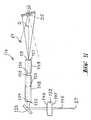
- the light remitted by the measurement spot 57is detected with the aid of the measurement optics 116 shown in FIG. 5 and for the spectral decomposition of the remitted light to the diffraction grating 55 and from there to a photodiode, not shown in the drawing, which is connected to the input of a computer via electronic circuits is connected to the evaluation of the spectral remissions.
- the light beam bundle 145 remitted by the measurement spot 57first passes through the spherical / cylindrical lens 132 already mentioned, whose longitudinal axis is aligned with the axis of rotation 119 before it is deflected by the deflecting mirror 133 at right angles to the axis of rotation 119.
- the spherical / cylindrical lens 132has a spherical surface 146 on the side facing the deflecting mirror 133 and a cylindrical surface 147 on the underside facing the measuring spot 57, the associated cylinder axis being perpendicular to the grating shaft 30 of the diffraction grating 55 and parallel to the plane of the drawing and to The plane of the measuring spot 57 runs.
- the light beam deflected by the deflecting mirror 133first crosses a first glass rod 148 and then a second glass rod 149 before it expands the diffraction grating 55 via an entry gap 59 with a width of 0.75 mm in the transverse direction to the entry gap 59.
- a holographic, concave reflection gratingwith 1250 lines / mm, which is optimized for blue in terms of its efficiency.
- the structure shown schematicallycorresponds to a monochromator.
- the light reflected by the diffraction grating 55reaches an exit slit 61 with a slit width of 0.75 mm and from there to the photodiode, not shown.
- the diffraction grating 55is rotated with the aid of the grating shaft 30 already mentioned.
- the blurring caused by the entrance slit width, the exit slit width and the rotation of the diffraction grating 55 during the measurementallow a spectral resolution of 10 nm.
- the signal fed to the handheld computeris calculated using a computational method unfolded in the manner customary in image science.
- the edge of the measuring spot 57is circular
- the edge of the light beam which acts on the entrance slit 59has an elliptical shape in order to achieve the highest possible light efficiency.
- the special type of imaging with the aid of the optical components shown in FIG. 5means that the round measurement spot 57 is imaged on an ellipse, the small axis of the ellipse corresponding to the slit width of the entry slit 59 of the monochromator.
- the long axis of the ellipseis about 3 mm long.
- the first glass rod 148is not only provided with a first slit diaphragm 152 and a second slit which extends perpendicular to the first slit diaphragm 152 aperture 153 provided, but it also has two crossed cylindrical surfaces 154 and 155.
- the first cylindrical surface 154 at the end of the first glass rod 148 facing the entrance pupil 152is essentially curved to the paper plane of FIG. 5.
- the cylinder axis of the The first cylindrical surface 154thus runs parallel to the axis of rotation 119 of the measuring head 4 and to the drawing plane of FIG. 5 and at right angles to the grating shaft 30.
- the first slit diaphragm 152is located at the point shown in FIG. 5.
- the first slit diaphragm 152extends in the plane of the drawing transversely to the direction of propagation of the light beam reflected by the deflecting mirror 133.
- the orientation of the second cylindrical surface 155 at the end of the first glass rod 148 facing the diffraction grating 55is selected such that the cylinder axis assigned to the cylindrical surface 155 runs parallel to the tilt axis and grating shaft 30 of the diffraction grating 55.
- the second glass rod 149is also provided with a first cylindrical surface 156 and a second cylindrical surface 157, the respectively assigned cylinder axes of which, as in the first glass rod 148, cross each other, the second cylindrical surface 157 assigned to the entry gap 59 being curved in the longitudinal direction of the entry gap 157 , so that the associated cylinder axis extends transversely to the inlet gap 59.
- a sharp anamorphic intermediate image of the round measuring spot 57 on the entrance slit 59 and the opening angle limits made on the slit diaphragms 152 and 153ensure that the entrance pupil of the measuring optics 116 is infinite. As a result of this and because the pick-up spot is somewhat larger than the light spot it is achieved that the measuring optics 116 are insensitive to distance to a certain extent. Distance is understood to mean the distance between the optics and the measurement sample.
Landscapes
- Physics & Mathematics (AREA)
- Spectroscopy & Molecular Physics (AREA)
- General Physics & Mathematics (AREA)
- Optics & Photonics (AREA)
- Chemical & Material Sciences (AREA)
- Life Sciences & Earth Sciences (AREA)
- Health & Medical Sciences (AREA)
- Analytical Chemistry (AREA)
- Biochemistry (AREA)
- General Health & Medical Sciences (AREA)
- Immunology (AREA)
- Pathology (AREA)
- Investigating Or Analysing Materials By Optical Means (AREA)
- Spectrometry And Color Measurement (AREA)
Abstract
Translated fromGermanDescription
Translated fromGermanDie Erfindung betrifft einen Meßkopf gemäß dem Oberbegriff des Anspruchs 1 und dem Oberbegriff des Nebenanspruchs 3.The invention relates to a measuring head according to the preamble of
Ein derartiger Meßkopf mit einer Projektionsoptik zur Beleuchtung einer Meßfläche und mit einer Meßoptik für das remittierte Meßlicht ist aus der US-A-4 078 858 bekannt und verfügt über eine Glühlampe, der zur Erzeugung eines Meßflecks eine Kollimatorlinse und ein Umlenkspiegel sowie eine weitere Sammellinse zugeordnet sind. Das vom Meßfleck unter 45° remittierte Licht gelangt in die Meßoptik, die den sphärischen Ringspiegel und den flachen ringförmigen Spiegel aufweist.Such a measuring head with projection optics for illuminating a measuring surface and with measuring optics for the remitted measuring light is known from US-A-4 078 858 and has an incandescent lamp which is assigned a collimator lens and a deflecting mirror and a further collecting lens for generating a measuring spot are. The light remitted by the measuring spot at 45 ° reaches the measuring optics, which have the spherical ring mirror and the flat ring-shaped mirror.
Die US-A-3 982 824 lehrt ein Spiegelsystem für elektromagnetische Strahlung oder Schallstrahlung, bei dem zur Vermeidung der Abschattung und achromatischen Aberration ein Primärspiegel und ein Sekundärspiegel zusammenwirken. Die Spiegelflächen des Primärspiegels sind von einem um die optische Achse rotierenden Parabelabschnitt als Erzeugenden gebildet, wobei der Parabel brennpunkt eine kreisförmige Brennlinie in einer Radialebene zu der optischen Achse des Spiegelsystemes beschreibt. Die Spiegelfläche des Sekundärspiegels des Spiegelsystems ist durch Drehen eines Teiles einer Ellipse um die Systemachse gebildet, wobei ein Brennpunkt der Ellipse auf der optischen Achse liegen bleibt, während der zweite Brennpunkt der Ellipse in einer kreisförmigen Brennlinie um die optische Achse des Spiegelsystems wandert, wenn die Ellipse rotiert. Sämtliche Axialstrahlen, welche auf den Primärspiegel treffen, werden bei dem bekannten Linsensystem an dem Brennpunkt des Sekundärspiegels gesammelt. Axialstrahlen, welche unmittelbar auf den Sekundärspiegel auftreffen werden in Richtung auf die optische Achse des Systems reflektiert und gelangen nicht zum Brennpunkt der Ellipse. Axiale Strahlen, die von einer punktförmigen Strahlungsquelle in einem großen Abstand von dem bekannten Spiegelsystem ausgehen, werden in vollkommener Weise fokussiert, so daß das Spiegelsystem nur für solche Strahlen eine fehlerfreie Abbildung ergibt.US-A-3 982 824 teaches a mirror system for electromagnetic radiation or acoustic radiation in which a primary mirror and a secondary mirror cooperate to avoid shadowing and achromatic aberration. The mirror surfaces of the primary mirror are formed by a parabola section rotating around the optical axis as generatrix, the parabola focal point describes a circular focal line in a radial plane to the optical axis of the mirror system. The mirror surface of the secondary mirror of the mirror system is formed by rotating part of an ellipse around the system axis, one focal point of the ellipse remaining on the optical axis, while the second focal point of the ellipse moves in a circular focal line around the optical axis of the mirror system when the Ellipse rotates. In the known lens system, all of the axial rays that strike the primary mirror are collected at the focal point of the secondary mirror. Axial rays that strike the secondary mirror directly are reflected in the direction of the optical axis of the system and do not reach the focal point of the ellipse. Axial rays that emanate from a point-shaped radiation source at a large distance from the known mirror system are perfectly focused, so that the mirror system only provides an error-free image for such rays.
Eine Reflektoranordnung zum Konzentrieren der von einer stabförmigen Blitzlampe ausgehenden Strahlung auf einen parallel zur Blitzlampe verlaufenden Stab aus einem Lasermaterial ist in der GB-A 281 265 beschrieben. Die Reflektoranordnung des optisch gepumpten Lasers ist als parallel zu den Längsachsen der Blitzlampe und des Laserstabes ausgerichteter Zylinder ausgebildet, der im Querschnitt im wesentlichen die Gestalt einer Ellipse hat, deren Brennpunkte bzw. Brennlinien einerseits durch die Blitzlampe und andererseits durch den Laserstab verlaufen. Um die bei einem reinen elliptischen Querschnitt auftretende Abschattung im Bereich der Hauptscheitel der Ellipsenform zu vermeiden, ist der Querschnitt des ellipsenförmigen zylindrischen Reflektors im Bereich der beiden Hauptscheitel speziell geformt, um das bei einem normalen ellipsenförmigen Spiegel in einen toten Winkel abgestrahlte Licht aufzufangen und zum Schnittpunkt der Nebenachse der Ellipse mit der Spiegelfläche zu reflektieren oder von dort aufzufangen. Dies wird dadurch erreicht, daß im Bereich der Hauptscheitel der Ellipsenform eine abweichende Ellipsenform vorgesehen ist, deren erster Brennpunkt mit der Längsachse der Blitzlampe bzw. des Laserstabes zusammenfällt und deren zweiter Brennpunkt dort liegt, wo die Nebenachse der Hauptellipse die Reflektorfläche schneidet. Die Querschnittsform dieses zylindrischen Reflektors entsteht somit durch Überlagerung einer Hauptellipse mit vier Nebenellipsen, wobei die Ellipsenflächen alle in der gleichen Ebene liegen.A reflector arrangement for concentrating the radiation emanating from a rod-shaped flash lamp onto a rod made of a laser material and running parallel to the flash lamp is described in GB-A 281 265. The reflector arrangement of the optically pumped laser is designed as a cylinder aligned parallel to the longitudinal axes of the flash lamp and the laser rod, which essentially has the shape of an ellipse in cross section, the focal points or focal lines of which run on the one hand through the flash lamp and on the other hand through the laser rod. In order to avoid the shadowing in the area of the main apex of the ellipse shape that occurs with a pure elliptical cross section, the Cross-section of the elliptical cylindrical reflector in the area of the two main apices specially shaped to collect the light emitted in a normal elliptical mirror in a blind spot and to reflect it at the intersection of the minor axis of the ellipse with the mirror surface or to collect it from there. This is achieved in that a different ellipse shape is provided in the area of the main apex of the ellipse shape, the first focal point of which coincides with the longitudinal axis of the flash lamp or the laser rod and the second focal point of which is where the minor axis of the main ellipse intersects the reflector surface. The cross-sectional shape of this cylindrical reflector is thus created by superimposing a main ellipse with four secondary ellipses, the ellipse surfaces all lying in the same plane.
Eine Vorrichtung zum Erfassen der optischen Dichte von Photographien, die in der US-A-3 244 062 beschrieben ist, verfügt über einen Meßkopf mit einer Projektionsoptik, die das Licht einer Glühlampe auf das photographische Material abbildet, und mit einer Meßoptik, die das im wesentlichen vertikal von der photographischen Oberfläche zurückgestreute Licht über einen Umlenkspiegel quer zur optischen Achse der Projektionsoptik auskoppelt und mit Hilfe einer Linse den Eingangsspalt eines Photoelektronen-Vervielfachers beaufschlagt. Die Projektionsoptik gestattet es, den Meßfleck unter einem Einfallswinkel von im wesentlichen 45° allseitig mit dem von der Glühlampe im Meßkopf stammenden Licht zu beaufschlagen. Die der Glühlampe zugeordnete Projektionsoptik enthält einen sphärischen Ringspiegel, der die Glühlampe umgibt, wobei der Glühfaden der Glühlampe sich entlang der optischen Achse des sphärischen Ringspiegel erstreckt. Das vom sphäri schen Ringspiegel parallel zur optischen Achse der Projektionsoptik ausgehende Lampenlicht wird mit Hilfe eines einfachen ringförmigen Spiegels auf die Meßfläche fokussiert. Die Qualität der Projektionsoptik und der Meßoptik der bekannten Vorrichtung ist für einfache Dichtemessungen bei der Bestimmung von optischen Remissionseigenschaften ausreichend.A device for detecting the optical density of photographs, which is described in US Pat. No. 3,244,062, has a measuring head with projection optics which images the light of an incandescent lamp onto the photographic material and with measuring optics which do so decouples essentially vertically scattered light back from the photographic surface via a deflecting mirror transverse to the optical axis of the projection optics and acts on the input slit of a photoelectron multiplier with the aid of a lens. The projection optics allow the light from the incandescent lamp in the measuring head to be applied to the measuring spot on all sides at an angle of incidence of essentially 45 °. The projection optics assigned to the incandescent lamp contain a spherical ring mirror which surrounds the incandescent lamp, the filament of the incandescent lamp extending along the optical axis of the spherical ring mirror. That of the spheri The ring mirror's outgoing lamp light parallel to the optical axis of the projection optics is focused on the measuring surface with the aid of a simple annular mirror. The quality of the projection optics and the measurement optics of the known device is sufficient for simple density measurements when determining optical reflectance properties.
Aus der US-A-4 025 200 ist eine Projektionsoptik für Laserlicht eines Densitometers oder Spektralphotometers bekannt. Das Laserlicht wird mit Hilfe eines quer zur Strahlrichtung ausgerichteten transparenten Rohres entlang einer rechtwinklig zur Rohrachse verlaufenden Ebene aufgeweitet. Nach dem Durchqueren einer Blende wird mit Hilfe einer zylindrischen Linse quer zur Aufweitungsrichtung eine Strahlbündelverengung bewirkt, um ein Abtaststrahlbündel zu erzeugen, wobei die Breite des Strahlenbündels justiert werden kann, wenn der Abstand der zylindrischen Linse zum abzutastenden Objekt verändert wird.From US-A-4 025 200 projection optics for laser light from a densitometer or spectrophotometer is known. The laser light is expanded with the help of a transparent tube aligned transversely to the beam direction along a plane perpendicular to the tube axis. After traversing an aperture, a beam is narrowed transversely to the direction of expansion with the aid of a cylindrical lens in order to generate a scanning beam, wherein the width of the beam can be adjusted if the distance between the cylindrical lens and the object to be scanned is changed.
Der Aufbau eines Spektralphotometers mit einer zeitlich parallelen Auswertung des Remissionsspektrums bewegter Meßflächen ist in der US-A-4 076 421 erörtert. Das Licht einer Xenon-Blitzlichtlampe gelangt in den Innenraum einer mit einem diffus reflektierenden Überzug versehenen Ulbricht Kugel, in der sich auch die Meßfläche des abzutastenden Musters befindet. Über eine Lochblende in der Kugel gelangt das von der Meßfläche remittierte Licht zu einer Linse, die es auf einen Spalt fokussiert. Dem Spalt ist ein konkaves Reflektionsgitter zugeordnet, durch das eine spektrale Zerlegung des Lichtes in der Weise erfolgt, daß einzelne Photodetektoren einer zeilenförmigen Anordnung mit Licht unterschiedlicher Wellenlänge beaufschlagt werden. Infolge der hohen Lichtleistung der Xenon-Blitzlichtlampe können die sich bei der defusen Reflektion an der Innenseite der Kugel ergebenden Intensitätsverluste hingenommen werden.The construction of a spectrophotometer with a temporally parallel evaluation of the reflectance spectrum of moving measurement surfaces is discussed in US Pat. No. 4,076,421. The light from a xenon flash lamp reaches the interior of an Ulbricht sphere provided with a diffusely reflective coating, in which the measuring surface of the pattern to be scanned is also located. Via a pinhole in the sphere, the light remitted by the measuring surface reaches a lens that focuses it on a slit. A concave reflection grating is assigned to the slit, by means of which the light is spectrally broken down in such a way that individual photodetectors with a line-shaped arrangement are included Light of different wavelengths can be applied. As a result of the high light output of the xenon flash lamp, the intensity losses resulting from the defuse reflection on the inside of the sphere can be accepted.
Aus der FR-A-1 527 717 ist ein tragbares Reflektometer bekannt, das einen Meßkopf mit einer Glühlampe und einer Projektionsoptik sowie eine Meßoptik aufweist. Das Licht der Glühlampe beaufschlagt über ein Filter einerseits direkt einen ersten Photowiderstand und andererseits über die Projektionsoptik und die Meßoptik einen zweiten Photowiderstand. Die beiden Photowiderstände sind in einer abgleichbaren Brückenschaltung angeordnet, mit deren Hilfe die Intensität des von einer Meßfläche reflektierten Lichtes ausgewertet werden kann. Der Glühfaden der Glühbirne im Meßkopf befindet sich im Brennpunkt eines Parabolspiegels, der eine Ausnehmung für das jeweils einzusetzende Filter aufweist. Das den Parabolspiegel im wesentlichen in Richtung der optischen Achse verlassende Licht gelangt über einen konischen Lichtwellenleiter oder Kollektor aus einem lichtbrechenden Material zu einer Koppelscheibe aus lichtbrechendem Material, deren Durchmesser kleiner als der Durchmesser des Parabolspiegels und kleiner als das gegenüberliegende Ende des konischen Kollektors ist. Beim Messen ist die Koppelscheibe fest gegen die Oberfläche des zu untersuchenden Objektes angedrückt, bei dem es sich insbesondere um Lebensmittel oder Agrarprodukte handelt. Entlang der Achse weist der konische Kollektor eine zylindrische Bohrung auf, in der sich ein zylindrischer Glasstab befindet. Auf der der Koppelscheibe zugewandten Seite hat der Glasstab eine ebene Stirnfläche, die mit der Koppelscheibe verklebt ist. Am gegenüberliegenden Ende ver fügt der Glasstab über eine sphärische Fläche, deren zugeordneter Brennpunkt auf der Fläche der lichtbrechenden Koppelscheibe liegt, die auf die zu untersuchende Meßfläche aufdrückbar ist. Innerhalb der Bohrung im konischen Kollektor befindet sich im Abstand von der sphärischen Oberfläche des Glasstabes der zweite Photowiderstand. Der erste, die Intensität des Ausgangslichts erfassende Photowiderstand befindet sich auf der Rückseite des mit dem Meßlicht beaufschlagten Photowiderstandes. Eine Spektralanalyse ist mit dem bekannten tragbaren Reflektometer nicht möglich, sondern lediglich eine Analyse der Remission unter Verwendung verschiedener auswechselbarer Filter.A portable reflectometer is known from FR-A-1 527 717, which has a measuring head with an incandescent lamp and projection optics and a measuring optic. The light of the incandescent lamp acts on a filter directly on the one hand on a first photoresistor and on the other hand on the projection optics and the measuring optics a second photoresistor. The two photoresistors are arranged in an adjustable bridge circuit, with the aid of which the intensity of the light reflected from a measuring surface can be evaluated. The filament of the light bulb in the measuring head is at the focal point of a parabolic mirror which has a recess for the filter to be used in each case. The light leaving the parabolic mirror essentially in the direction of the optical axis passes via a conical optical waveguide or collector made of a refractive material to a coupling disc made of refractive material, the diameter of which is smaller than the diameter of the parabolic mirror and smaller than the opposite end of the conical collector. When measuring, the coupling disc is pressed firmly against the surface of the object to be examined, which is, in particular, food or agricultural products. Along the axis, the conical collector has a cylindrical bore in which there is a cylindrical glass rod. On the side facing the coupling plate, the glass rod has a flat end face which is glued to the coupling plate. At the opposite end ver adds the glass rod over a spherical surface, the associated focal point of which lies on the surface of the light-refractive coupling disc, which can be pressed onto the measuring surface to be examined. The second photoresistor is located within the hole in the conical collector at a distance from the spherical surface of the glass rod. The first photoresistor, which detects the intensity of the output light, is located on the back of the photoresistor to which the measuring light is applied. Spectral analysis is not possible with the known portable reflectometer, but only an analysis of the reflectance using various interchangeable filters.
Ausgehend von diesem Stand der Technik liegt der Erfindung die Aufgabe zugrunde, einen Meßkopf der eingangs genannten Art zu schaffen, der es gestattet, das vom Meßfleck remittierte Meßlicht mit einer ausreichenden Präzision und Intensität einem Gittermonochromator zuzuführen, um eine Spektralanalyse des remittierten Lichtes durchführen zu können.Starting from this prior art, the invention has for its object to provide a measuring head of the type mentioned, which allows the measuring light remitted from the measuring spot to be fed with sufficient precision and intensity to a grating monochromator in order to be able to carry out a spectral analysis of the remitted light .
Diese Aufgabe wird bezüglich der Beleuchtungsoptik von den Merkmalen des kennzeichnenden Teils des Anspruchs 1 und bezüglich der Meßoptik von den kennzeichnenden Merkmalen des unabhängigen Anspruchs 3 gelöst.This object is achieved with respect to the illumination optics by the features of the characterizing part of
Zweckmäßige Ausgestaltungen und Weiterbildungen der Erfindung sind Gegenstand von Unteransprüchen.Expedient refinements and developments of the invention are the subject of dependent claims.
Im folgenden wird ein Ausführungsbeispiel eines erfindungsgemäßen Meßkopfes für ein Handgerät zur Erfassung von photometrischen Daten anhand der Zeichnung näher erläutert. Es zeigen:
- Fig. 1 eine Seitenansicht des mit einem erfindungsgemäßen Meßkopf ausgerüsteten Handgerätes, teilweise im Schnitt,
- Fig. 2 eine Draufsicht auf das Handgerät,
- Fig. 3 ein Ausführungsbeispiel für die Beleuchtungsoptik des Meßkopfes im Schnitt,
- Fig. 4 eine gegenüber Fig. 3 vergrößerte Schnittdarstellung des asphärischen Spiegels der Beleuchtungsoptik zur Veranschaulichung der Formgebung der verspiegelten Fläche und
- Fig. 5 ein Ausführungsbeispiel für die im Meßkopf angeordnete Meßoptik und den prinzipiellen Aufbau eines zugeordneten Monochromators mit einem Beugungsgitter im Schnitt.
- 1 is a side view of the handheld device equipped with a measuring head according to the invention, partly in section,
- 2 is a plan view of the handheld device,
- 3 shows an exemplary embodiment of the illumination optics of the measuring head in section,
- Fig. 4 is an enlarged sectional view of FIG. 3 of the aspherical mirror of the illumination optics to illustrate the shape of the mirrored surface and
- Fig. 5 shows an embodiment of the measuring optics arranged in the measuring head and the basic structure of an associated monochromator with a diffraction grating in section.
Das in Fig. 1 in einer Seitenansicht teilweise aufgeschnitten dargestellte Gerät entspricht in seinen äußeren Abmaßen einem Aufsichts-Hand-Densitometer und ist daher entsprechend kompakt aufgebaut. Im Gegensatz zu einem üblichen Densitometer gestattet es das in Fig. 1 dargestellte Handgerät jedoch, neben densitometrischen Größen auch Remissions- und Dichte-Spektren sowie farbmetrische Größen zu erfassen.The device shown partially cut away in FIG. 1 corresponds in its outer dimensions to a hand-held densitometer and is therefore of a correspondingly compact design. In contrast to a conventional densitometer, the hand-held device shown in FIG. 1, however, allows not only densitometric variables but also reflectance and density spectra and colorimetric variables to be recorded.
Das Handgerät verfügt über ein Gehäuse 1, in dem eine oder mehrere Printplatten 2, 3 für eine Meßwertverarbeitungs- und Steuerlogik angeordnet sind, was im oberen Teil des aufgeschnittenen Gehäuses 1 schematisch dargestellt ist.The handheld device has a
Aus der linken Seitenwand des Gehäuses 1 ragt ein Meßkopf 4 heraus, der zwischen einer in Fig. 1 mit durchgezogenen Linien dargestellten Ruhestellung und einer in Fig. 1 gestrichelt dargestellten Arbeitsstellung entlang dem Doppelpfeil 5 parallel zum Boden 6 des Gehäuses 1 verfahren werden kann. In der eingefahrenen Ruhestellung ragt eine Visierplatte 7 über den Rand des Meßkopfes 4 hinaus, was insbesondere in Fig. 2 deutlich zu erkennen ist. Die Visierplatte 7 verfügt über eine Meßblende 8, die dazu dient, die Lage und Größe eines Meßfleckes 57 des Meßkopfes 4 in der Arbeitsstellung anzuzeigen und Streulicht abzuschirmen.A
Wenn der Meßkopf 4 aus der in den Fig. 1 und 2 dargestellten Ruhestellung in die in den Fig. 1 und 2 gestrichelt dargestellte Arbeitsstellung oder Meßposition ausgefahren ist, verläuft die optisch wirksame Achse des Meßkopfes 4 genau durch den Mittelpunkt der Meßblende 8.When the
In den Fig. 1 und 2 erkennt man weiterhin einen Filterradantrieb 9, der mit einem im Meßkopf 4 vorgesehenen Filterrad in Eingriff steht und es gestattet, in den Strahlengang des Meßkopfes 4 je nach Wunsch einen Polarisator für das Messen nasser Druckbogen, ein D65-Konversionsfilter für die Berücksichtigung der Fluoreszenz oder eine Blende ohne Filter einzubringen. Der Filterradantrieb 9 hat somit drei Positionen, die von Hand eingestellt werden, jedoch auf einem Anzeigefeld 10, beispielsweise einem Flüssigkristall-Display, dargestellt werden können.1 and 2 you can also see a
Das Anzeigefeld 10 dient auch zur Darstellung der mit dem Handgerät erfaßten Meßwerte in numerischer Form oder in Gestalt von Spektren oder Balkendiagrammen. Zur Bedienung des Handgerätes sind um das Anzeigefeld 10 eine Reihe von Tasten einer Tastatur 11 sowie mehrere den Anzeigen auf dem Anzeigefeld 10 zugeordnete Hinweisfelder 12 vorgesehen. Das Anzeigefeld 10, die Tastatur und die Hinweisfelder 12 befinden sich auf der Oberseite 13 des Gehäuses 1, wobei auf der von dem Meßkopf 4 wegweisenden Seite eine großflächige Meßtaste 14 zum Auslösen eines Meßvorganges vorgesehen ist.The
Beim Betätigen der Meßtaste 14 wird die Meßwertverarbeitungs- und Steuerlogik veranlaßt, den Meßkopf 4 aus der Ruhestellung in die Arbeitsstellung zu verfahren, um mit Hilfe einer im Innern des Gehäuses 1 vorgesehenen Spektralkammer mit einem in Fig. 5 dargestellten Beugungsgitter 55 das Spektrum des Lichtes zu erfassen, das beispielsweise von einem Druckbogen, auf dem das Handgerät ruht, an der Stelle der Meßblende 8 remittiert wird. Die Verarbeitung des Remissions-Spektrums erfolgt mit Hilfe der Meßwertverarbeitungs- und Steuerlogik. Nach dem Erfassen des Spektrums fährt der Meßkopf 4 wieder in seine Ruhestellung zurück, bis ein erneuter Meßvorgang durch Betätigen der Meßtaste 14 ausgelöst wird.When the
Das Verfahren des Meßkopfes 4 erfolgt mit Hilfe eines in der Zeichnung nicht dargestellten Meßwagens, der innerhalb des Gehäuses 1 längs verschieblich geführt ist.The measuring
Der Meßkopf 4 enthält eine Meßkopfoptik, die aus der in Fig. 3 dargestellten Beleuchtungsoptik 115 und der in Fig. 5 dargestellten Meßoptik 116 besteht. Fig. 5 zeigt weiterhin das Beugungsgitter 55, dessen Halterung an einer drehbaren Gitterwelle 30 befestigt ist, um durch Verdrehen der Gitterwelle 30 ein Durchstimmen des zu erfassenden Spektralbereichs auszuführen.The measuring
Die im Meßkopf 4 untergebrachte Meßkopfoptik hat einerseits die Aufgabe, den Meßfleck 57, der in den Fig. 3 und 5 durch einen Strich veranschaulicht ist, zu beleuchten, und andererseits das vom beleuchteten Meßfleck 57 remittierte Licht aufzufangen und für die spektrale Zerlegung auf das Beugungsgitter 55 zu werfen. Die in Fig. 3 dargestellte Beleuchtungsoptik gestattet es, den Meßfleck 57 unter einem Einfallswinkel von im wesentlichen 45° ± 5° allseitig mit dem von einer Glühlampe 117 stammenden Licht zu beaufschlagen, wobei das von dem Meßfleck 57 in die Meßoptik 116 zurückgestrahlte Meßlicht unter einem Meßwinkel von im wesentlichen 0° ± 5° empfangen wird. Der Durchmesser des Meßflecks 57 beträgt 3 mm. Das von der Glühlampe 117 ausgesandte Glühlampenlicht stellt eine Beleuchtung mit der Lichtart A dar, wobei die Glühlampe so ausgebildet ist, daß sie das Meßlicht mit der geforderten Farbtemperatur zur Verfügung stellt.The measuring head optics housed in the measuring
Die Glühlampe 117 ist im Meßkopf 4 so angeordnet, daß sich ihr Glühfaden 118 auf der Längsachse bzw. Rotationsachse 119 der rotationssymmetrisch aufgebauten Beleuchtungsoptik 115 befindet. Außerdem liegt der Glühfaden 118 in einem ersten Ellipsenbrennpunkt, der einer Asphäre 120 zugeordnet ist, die in Fig. 3 oberhalb der Glühlampe 117 dargestellt ist und ebenfalls rotationssymmetrisch aufgebaut ist. Die Asphäre 120 ist auf der zur Glühlampe 117 weisenden Seite verspiegelt und hat die in Fig. 4 vergrößert gezeigte Gestalt.The
Auf der zur Glühlampe 117 weisenden verspiegelten Seite verfügt die Asphäre 120 über eine ringförmige Mulde 121 die sich um die Rotationsachse 119 erstreckt und deren Innenrand eine zentrale Erhebung 122 bildet, die auf der Rotationsachse 119 liegt. Der Außenrand 123 der Mulde 121 ragt weiter nach unten in Richtung zur Glühlampe 117 als der Innenrand mit der zentralen Erhebung 122.On the mirrored side facing the
Die Mulde 121 hat im Querschnitt die Gestalt eines Ellipsensegments. Fig. 4 zeigt, wie die Gestalt der Mulde 121 dadurch entsteht, daß eine Ellipse 127 mit ihrem ersten Brennpunkt 124 auf die Mittellängsachse bzw. Rotationsachse 119 so gelegt wird, daß der zweite Brennpunkt 125 von der Rotationsachse 119 einen Abstand hat. Die Lage des zweiten Brennpunkts 125 ergibt sich aus dem Abstand einer ringförmigen Pupille 126, die in Fig. 3 dargestellt ist. Die Mulde 121 hat diejenige Form, die entsteht, wenn die in Fig. 4 dargestellte Ellipse 127 um die Rotationsachse 119 gedreht wird, wobei die Lage des Brennpunktes 124 und die Lage des in Fig. 4 gezeigten Schnittpunktes 128 der Ellipse 127 mit der Rotationsachse 119 im Raum bei einer Drehung der Ellipse 127 fest bleiben. Die Form der Ellipse 127 ist so gewählt, daß das Verhältnis der Abstände zwischen dem Scheitelpunkt 160 und dem ersten Brennpunkt 124 einerseits und dem Scheitelpunkt 160 und dem zweiten Brennpunkt 125 andererseits sich etwa wie 1 : 3 verhält.The
Das von der Asphäre 120 reflektierte Licht tritt durch die bereits erwähnte Pupille 126 hindurch, die um den Kreis ausgebildet ist, der vom zweiten Brennpunkt 125 bei der beschriebenen Rotation der Ellipse 127 ausgeführt wird. Die Pupille 126 ist an ihrem inneren Rand 129 von einem Blendenring 130 begrenzt, der eine Öffnung 131 für ein in der Zeichnung nicht dargestelltes Lichtführungsrohr aufweist, das u.a. zur Befestigung der in Fig. 5 dargestellten sphärisch/zylindrischen Linse 132 und eines Umlenkspiegels 133 dient. Durch geeignete Dimensionierung der Größe des quadratischen Glühfadens 118 (0,6 x 0,6 mm) der Glühlampe 117 wird erreicht, daß praktisch alles Licht der Glühlampe 117, das in einem Raumwinkel von ± 70° abgestrahlt wird, durch die ringförmige Pupille 126 fällt und damit der Lichtwirkungsgrad der Beleuchtungsoptik 115 sehr hoch wird. Dies ist wichtig, damit eine Glühlampe 117 mit möglichst geringer Leistung, von z.B. etwa 2 Watt, verwendet werden kann (Batteriebetrieb).The light reflected by the asphere 120 passes through the already mentioned
Der Blendenring 130 ist koaxial zur Rotationsachse 119 angeordnet und von einem ringförmigen Glaskörper 134 umgeben, der an seiner Unterseite eine sphärisch gewölbte, konkave Ringfläche mit einem aufgedampften sphärischen Ringspiegel 135 aufweist. Die untere Innenkante 136 des ringförmigen Glaskörpers 134 bildet die äußere Begrenzung der bereits erwähnten ringförmigen Pupille 126.The
Unterhalb dem ringförmigen Glaskörper 134 ist ein Glasring 137 angeordnet, dessen zentrale Öffnung 139 sich in der von dem ringförmigen Glaskörper 134 wegweisenden Richtung konisch verengt. Auf der vom ringförmigen Glaskörper 134 wegweisenden Unterseite ist der Glasring 137 mit einer flachen ringförmigen Spiegelfläche 138 versehen. Um die konische Öffnung 139 herum weist der Glasring 137 ein ringförmiges Lichtdurchtrittsfenster 140 auf.A
Wenn in den Strahlengang des Meßkopfes 4 ein Polarisator oder ein sonstiges Filter eingebracht wird, befindet sich dies an der Stelle des in Fig. 3 dargestellten Polarisators 141. Der vom Lampenlicht beleuchtete Meßfleck 57 ist in Fig. 3 unterhalb dem Glasring 137 und dem Polarisator 141 zu erkennen. Der Strahlengang des von der Glühlampe 117 ausgesandten Lichtes ist in Fig. 3 veranschaulicht und zeigt wie das Lampenlicht von der Asphäre 120 zur ringförmigen Pupille 126 reflektiert wird. Nach dem Durchgang durch die Pupille 126 durchquert das Licht den Glasring 137 und wird von der ringförmigen Spiegelfläche 138 in Richtung auf den sphärischen Ringspiegel 135 an der Unterseite des ringförmigen Glaskörpers 134 reflektiert. Der sphärische Ringspiegel 135 reflektiert das Lampenlicht zum ringförmigen Lichtdurchtrittsfenster 140. Nach dem Verlassen des Lichtdurchtrittsfensters 140 und Durchqueren des gegebenenfalls vorhandenen Polarisators 141 beaufschlagt das Lampenlicht den Meßfleck 57.If a polarizer or another filter is introduced into the beam path of the measuring
Der Fachmann erkennt, daß die beschriebene Abbildungsoptik die Asphäre 120 so auf den Meßfleck 57 abbildet, daß der Außenrand 123 der Asphäre 120 scharf auf den Rand des Meßflecks 57 abgebildet wird. Der Innenrand 122 wird dabei unscharf ins Zentrum des Meßflecks 57 abgebildet. Die Abstände und Krümmungen sind so gewählt, daß der Meßfleck 57 die gewünschte Größe von 3 mm Durchmesser erhält und der Beleuchtungswinkel von 45° ± 5° eingehalten wird.Those skilled in the art will recognize that the imaging optics described images the
In Fig. 3 erkennt man oben rechts in der Nähe der Glühlampe 117 eine Auskopplungsblende 158, die es gestattet, das Licht der Glühlampe 117 zu einer Lampenüberwachung auszukoppeln.In FIG. 3, a
Das vom Meßfleck 57 remittierte Licht wird mit Hilfe der in Fig. 5 dargestellten Meßoptik 116 erfaßt und zur spektralen Zerlegung des remittierten Lichtes zum Beugungsgitter 55 und von dort zu einer in der Zeichnung nicht dargestellten Photodiode geführt, die über elektronische Schaltungen mit dem Eingang eines Rechners zur Auswertung der spektralen Remissionen verbunden ist.The light remitted by the
Das vom Meßfleck 57 remittierte Lichtstrahlbündel 145 durchquert zunächst die bereits erwähnte sphärisch/zylindrische Linse 132, deren Längsachse mit der Rotationsachse 119 fluchtet, bevor es von dem Umlenkspiegel 133 rechtwinklig zur Rotationsachse 119 umgelenkt wird.The
Die sphärisch/zylindrische Linse 132 verfügt auf der zum Umlenkspiegel 133 weisenden Seite über eine sphärische Oberfläche 146 und auf der zum Meßfleck 57 weisenden Unterseite über eine zylindrische Fläche 147, wobei die zugeordnete Zylinderachse rechtwinklig zur Gitterwelle 30 des Beugungsgitter 55 und parallel zur Zeichenebene sowie zur Ebene des Meßflecks 57 verläuft.The spherical /
Das vom Umlenkspiegel 133 umgelenkte Lichtstrahlbündel durchquert zunächst einen ersten Glasstab 148 und danach einen zweiten Glasstab 149, bevor es über einen Eintrittsspalt 59 mit einer Breite von 0,75 mm in Querrichtung zum Eintrittsspalt 59 aufgeweitet das Beugungsgitter 55 beaufschlagt. Bei dem Beugungsgitter 55 zur spektralen Zerlegung des Lichtes handelt es sich um ein holographisches, konkaves Reflexionsgitter mit 1250 Linien/mm, das bezüglich seines Wirkungsgrades auf Blau optimiert ist. Der schematisch dargestellte Aufbau entspricht einem Monochromator.The light beam deflected by the deflecting
Unter einem Winkel D von 25° gelangt das vom Beugungsgitter 55 reflektierte Licht zu einem Austrittsspalt 61 mit einer Spaltbreite von 0,75 mm und von dort zu der nicht gezeigten Photodiode. Um das ganze Spektrum zu messen, wird das Beugungsgitter 55 mit Hilfe der bereits erwähnten Gitterwelle 30 gedreht. Die Unschärfen, die durch die Eintrittsspaltbreite, die Austrittsspaltbreite und die Drehung des Beugungsgitters 55 während der Messung entstehen, erlauben eine spektrale Auflösung von 10 nm. Um die Schärfe noch etwas zu verbessern, wird das dem Rechner des Handgerätes zugeführte Signal mit einer rechnerischen Methode in der in der Bildwissenschaft üblichen Weise entfaltet.At an angle D of 25 °, the light reflected by the
Während der Rand des Meßflecks 57 kreisförmig ist, hat der Rand des den Eintrittsspalt 59 beaufschlagenden Lichtbündels eine elliptische Gestalt, um eine möglichst hohe Lichtausbeute zu erzielen. Durch die spezielle Art der Abbildung mit Hilfe der in Fig. 5 gezeigten optischen Komponenten wird erreicht, daß der runde Meßfleck 57 auf eine Ellipse abgebildet wird, wobei die kleine Achse der Ellipse der Spaltbreite des Eintrittsspalts 59 des Monochromators entspricht. Die große Achse der Ellipse hat eine Länge von etwa 3 mm. Dazu ist der erste Glasstab 148 nicht nur mit einer ersten Spaltblende 152 und einer sich senkrecht zur ersten Spaltblende 152 erstreckenden zweiten Spalt blende 153 versehen, sondern er verfügt weiterhin auch noch über zwei gekreuzt angeordnete zylindrische Flächen 154 und 155. Die erste zylindrische Fläche 154 an dem zur Eintrittspupille 152 weisenden Ende des ersten Glasstabs 148 verläuft im wesentlichen gekrümmt zur Papierebene der Fig. 5. Die Zylinderachse der ersten zylindrischen Fläche 154 verläuft somit parallel zur Rotationsachse 119 des Meßkopfes 4 und zur Zeichenebene der Fig. 5 sowie rechtwinklig zur Gitterwelle 30. Die erste Spaltblende 152 befindet sich an der in Fig. 5 gezeigten Stelle. Sie ist jedoch in der Zeichnung nicht erkennbar, da ihre Ränder oberhalb und unterhalb der Zeichenebene liegen, d.h. die erste Spaltblende 152 erstreckt sich in der Zeichenebene quer zur Ausbreitungsrichtung des vom Umlenkspiegel 133 reflektierten Lichtbündels.While the edge of the measuring
Die Orientierung der zweiten zylindrischen Fläche 155 am zum Beugungsgitter 55 weisenden Ende des ersten Glasstabs 148 ist so gewählt, daß die der zylindrischen Fläche 155 zugeordnete Zylinderachse parallel zur Kippachse und Gitterwelle 30 des Beugungsgitters 55 verläuft.The orientation of the second
Der zweite Glasstab 149 ist ebenfalls mit einer ersten zylindrischen Fläche 156 und einer zweiten zylindrischen Fläche 157 versehen, deren jeweils zugeordnete Zylinderachsen wie beim ersten Glasstab 148 gekreuzt zueinander verlaufen, wobei die dem Eintrittsspalt 59 zugeordnete zweite zylindrische Fläche 157 in Längsrichtung des Eintrittsspalts 157 gewölbt ist, so daß die zugeordnete Zylinderachse quer zum Eintrittsspalt 59 verläuft.The
Durch eine scharfe anamorphotische Zwischenabbildung des runden Meßflecks 57 auf den Eintrittsspalt 59 und durch die getroffenen Öffnungswinkelbegrenzungen an den Spaltblenden 152 und 153 wird erreicht, daß die Eintrittspupille der Meßoptik 116 im Unendlichen liegt. Dadurch und weil der Aufpick-Fleck etwas größer ist als der Leucht-Fleck wird erreicht, daß die Meßoptik 116 in gewissem Rahmen abstandsunempfindlich ist. Unter Abstand wird dabei die Distanz zwischen der Optik und der Meßprobe verstanden.A sharp anamorphic intermediate image of the
Claims (11)
Translated fromGermanApplications Claiming Priority (2)
| Application Number | Priority Date | Filing Date | Title |
|---|---|---|---|
| CH360/88 | 1988-02-02 | ||
| CH36088 | 1988-02-02 |
Publications (2)
| Publication Number | Publication Date |
|---|---|
| EP0327499A1true EP0327499A1 (en) | 1989-08-09 |
| EP0327499B1 EP0327499B1 (en) | 1992-01-08 |
Family
ID=4185245
Family Applications (1)
| Application Number | Title | Priority Date | Filing Date |
|---|---|---|---|
| EP89810061AExpired - LifetimeEP0327499B1 (en) | 1988-02-02 | 1989-01-24 | Measuring head |
Country Status (4)
| Country | Link |
|---|---|
| US (1) | US4929084A (en) |
| EP (1) | EP0327499B1 (en) |
| JP (1) | JPH01291130A (en) |
| DE (1) | DE58900674D1 (en) |
Cited By (2)
| Publication number | Priority date | Publication date | Assignee | Title |
|---|---|---|---|---|
| US5982501A (en)* | 1997-05-13 | 1999-11-09 | Gretag-Macbeth Ag | Reflectance measuring device |
| DE102016212088A1 (en)* | 2016-07-04 | 2018-01-04 | Robert Bosch Gmbh | Device for limiting an angle of incidence for a spectrometer and method for operating such a device |
Families Citing this family (7)
| Publication number | Priority date | Publication date | Assignee | Title |
|---|---|---|---|---|
| EP0523308A1 (en)* | 1991-07-19 | 1993-01-20 | GRETAG Aktiengesellschaft | Photometrical method and computer controlled photometer |
| EP0603448B1 (en)* | 1992-12-23 | 1998-08-26 | GRETAG Aktiengesellschaft | Hand-held densitometer |
| US5475571A (en)* | 1994-03-30 | 1995-12-12 | Ford Motor Company | Ring Light collector |
| JP4086664B2 (en)* | 2003-01-07 | 2008-05-14 | 三菱電機株式会社 | Illumination optical system structure and projection display device |
| DE102013104986A1 (en)* | 2013-05-15 | 2014-12-04 | Limo Patentverwaltung Gmbh & Co. Kg | Device for acting on the outside of a rotationally symmetrical component with laser radiation |
| USD763712S1 (en)* | 2015-04-30 | 2016-08-16 | Exfo Inc. | Portable test instrument |
| USD764328S1 (en)* | 2015-05-01 | 2016-08-23 | Exfo Inc. | Portable test instrument |
Citations (7)
| Publication number | Priority date | Publication date | Assignee | Title |
|---|---|---|---|---|
| US3244062A (en)* | 1960-04-12 | 1966-04-05 | Gen Aniline & Film Corp | Photo-electrical sensitometric measuring apparatus |
| FR1527717A (en)* | 1966-07-06 | 1968-06-07 | Agronomique Inst Nat Rech | Reflectometer |
| DE2258923A1 (en)* | 1971-12-01 | 1973-06-07 | Raytheon Co | MIRROR SYSTEM |
| US4025200A (en)* | 1975-02-03 | 1977-05-24 | Zeineh Rashid A | Soft and line laser |
| US4076421A (en)* | 1976-03-23 | 1978-02-28 | Kollmorgen Technologies Corporation | Spectrophotometer with parallel sensing |
| US4078858A (en)* | 1975-12-30 | 1978-03-14 | Gretag Aktiengesellschaft | Measuring head |
| GB2181265A (en)* | 1985-10-08 | 1987-04-15 | Ferranti Plc | Reflector for electromagnetic radiation |
Family Cites Families (13)
| Publication number | Priority date | Publication date | Assignee | Title |
|---|---|---|---|---|
| JPS5140469B2 (en)* | 1973-10-04 | 1976-11-04 | ||
| US3956586A (en)* | 1973-11-01 | 1976-05-11 | Aga Aktiebolag | Method of optical scanning |
| FR2364437A1 (en)* | 1976-09-13 | 1978-04-07 | Kollmorgen Tech Corp | SPECTROPHOTOMETER WITH PARALLEL SIGNAL COLLECTION |
| US4093991A (en)* | 1977-01-26 | 1978-06-06 | Hunter Associates Laboratory, Inc. | Spectrophotometer-digital data processing system for appearance measurements providing fast and accurate standardization, ease of use for different appearance measurements and fast response |
| JPS5645832A (en)* | 1979-09-21 | 1981-04-25 | Moritetsukusu:Kk | Production of extra-micro roller |
| JPS5666731A (en)* | 1979-11-05 | 1981-06-05 | Hitachi Ltd | Sample coloring device |
| JPS5817407A (en)* | 1981-07-23 | 1983-02-01 | Nippon Sheet Glass Co Ltd | Lens body and its manufacture |
| DE3313668C2 (en)* | 1983-04-15 | 1985-06-13 | Klaus 1000 Berlin Schröter | Colorimeter |
| JPS6129452A (en)* | 1984-07-20 | 1986-02-10 | Ricoh Co Ltd | Loader of disc cassette |
| DE3575350D1 (en)* | 1984-08-08 | 1990-02-15 | Gretag Ag | Densitometer. |
| JPS61275710A (en)* | 1985-05-31 | 1986-12-05 | Hoya Corp | Distributed index anamorphic plane microlens and its manufacture |
| US4770530A (en)* | 1986-04-23 | 1988-09-13 | Kollmorgen Corporation | Remote spectrophotometer |
| US4865456A (en)* | 1987-10-01 | 1989-09-12 | Gretag Aktiengesellschaft | Measuring head |
- 1989
- 1989-01-24USUS07/300,936patent/US4929084A/ennot_activeExpired - Fee Related
- 1989-01-24DEDE8989810061Tpatent/DE58900674D1/ennot_activeExpired - Fee Related
- 1989-01-24EPEP89810061Apatent/EP0327499B1/ennot_activeExpired - Lifetime
- 1989-02-02JPJP1024755Apatent/JPH01291130A/enactivePending
Patent Citations (7)
| Publication number | Priority date | Publication date | Assignee | Title |
|---|---|---|---|---|
| US3244062A (en)* | 1960-04-12 | 1966-04-05 | Gen Aniline & Film Corp | Photo-electrical sensitometric measuring apparatus |
| FR1527717A (en)* | 1966-07-06 | 1968-06-07 | Agronomique Inst Nat Rech | Reflectometer |
| DE2258923A1 (en)* | 1971-12-01 | 1973-06-07 | Raytheon Co | MIRROR SYSTEM |
| US4025200A (en)* | 1975-02-03 | 1977-05-24 | Zeineh Rashid A | Soft and line laser |
| US4078858A (en)* | 1975-12-30 | 1978-03-14 | Gretag Aktiengesellschaft | Measuring head |
| US4076421A (en)* | 1976-03-23 | 1978-02-28 | Kollmorgen Technologies Corporation | Spectrophotometer with parallel sensing |
| GB2181265A (en)* | 1985-10-08 | 1987-04-15 | Ferranti Plc | Reflector for electromagnetic radiation |
Cited By (2)
| Publication number | Priority date | Publication date | Assignee | Title |
|---|---|---|---|---|
| US5982501A (en)* | 1997-05-13 | 1999-11-09 | Gretag-Macbeth Ag | Reflectance measuring device |
| DE102016212088A1 (en)* | 2016-07-04 | 2018-01-04 | Robert Bosch Gmbh | Device for limiting an angle of incidence for a spectrometer and method for operating such a device |
Also Published As
| Publication number | Publication date |
|---|---|
| EP0327499B1 (en) | 1992-01-08 |
| US4929084A (en) | 1990-05-29 |
| JPH01291130A (en) | 1989-11-22 |
| DE58900674D1 (en) | 1992-02-20 |
Similar Documents
| Publication | Publication Date | Title |
|---|---|---|
| DE2712074C3 (en) | Device for measuring the diffuse reflection of surfaces | |
| DE2901738C2 (en) | Spectrophotometer | |
| DE4343076C2 (en) | Device for photothermal testing of a surface of an object in particular being moved | |
| DE69622588T2 (en) | fluorometer | |
| DE2740724C3 (en) | Spectrophotometer | |
| EP0311561B1 (en) | Measuring head | |
| EP3504535B1 (en) | Measuring device for measuring absorption of gases | |
| WO2013064395A1 (en) | Device for optically determining the surface geometry of a three-dimensional sample | |
| DE69334168T2 (en) | SPECTROMETER FOR LENS KNIVES | |
| DE2433682C3 (en) | Device for monitoring a material web or another scanning plane | |
| DE3304780C2 (en) | ||
| DE10151312A1 (en) | Surface plasmon resonance sensor | |
| WO2010127872A1 (en) | Device and method for angularly resolved scattered light measurement | |
| DE3143137C2 (en) | Reflection-blocking, focusing optical device | |
| EP0327499B1 (en) | Measuring head | |
| DE102014215193A1 (en) | Measuring arrangement for reflection measurement | |
| DE2103318B2 (en) | Scatter photometer | |
| DE10107210C1 (en) | microscope | |
| DE4138679C1 (en) | ||
| EP0359167A2 (en) | Refractometer with an index-dependent aperture division | |
| DE2136634A1 (en) | Optical arrangement for a device for analyzing a sample by atomic spectroscopy | |
| EP3614130B1 (en) | Device for determining optical properties of samples | |
| DE19811150A1 (en) | Thin layer chromatography device | |
| DE3152972T1 (en) | OPTICAL SYSTEM WITH MULTIPLE-DRIVE RADIATION | |
| EP0864083A1 (en) | Nephelometer |
Legal Events
| Date | Code | Title | Description |
|---|---|---|---|
| PUAI | Public reference made under article 153(3) epc to a published international application that has entered the european phase | Free format text:ORIGINAL CODE: 0009012 | |
| 17P | Request for examination filed | Effective date:19890126 | |
| AK | Designated contracting states | Kind code of ref document:A1 Designated state(s):CH DE FR GB IT LI | |
| 17Q | First examination report despatched | Effective date:19910130 | |
| GRAA | (expected) grant | Free format text:ORIGINAL CODE: 0009210 | |
| AK | Designated contracting states | Kind code of ref document:B1 Designated state(s):CH DE FR GB IT LI | |
| ET | Fr: translation filed | ||
| REF | Corresponds to: | Ref document number:58900674 Country of ref document:DE Date of ref document:19920220 | |
| ITF | It: translation for a ep patent filed | ||
| GBT | Gb: translation of ep patent filed (gb section 77(6)(a)/1977) | ||
| PLBE | No opposition filed within time limit | Free format text:ORIGINAL CODE: 0009261 | |
| STAA | Information on the status of an ep patent application or granted ep patent | Free format text:STATUS: NO OPPOSITION FILED WITHIN TIME LIMIT | |
| 26N | No opposition filed | ||
| PGFP | Annual fee paid to national office [announced via postgrant information from national office to epo] | Ref country code:GB Payment date:19981211 Year of fee payment:11 | |
| PGFP | Annual fee paid to national office [announced via postgrant information from national office to epo] | Ref country code:FR Payment date:19981215 Year of fee payment:11 | |
| PGFP | Annual fee paid to national office [announced via postgrant information from national office to epo] | Ref country code:DE Payment date:19981217 Year of fee payment:11 | |
| PGFP | Annual fee paid to national office [announced via postgrant information from national office to epo] | Ref country code:CH Payment date:19981229 Year of fee payment:11 | |
| PG25 | Lapsed in a contracting state [announced via postgrant information from national office to epo] | Ref country code:GB Free format text:LAPSE BECAUSE OF NON-PAYMENT OF DUE FEES Effective date:20000124 | |
| PG25 | Lapsed in a contracting state [announced via postgrant information from national office to epo] | Ref country code:LI Free format text:LAPSE BECAUSE OF NON-PAYMENT OF DUE FEES Effective date:20000131 Ref country code:CH Free format text:LAPSE BECAUSE OF NON-PAYMENT OF DUE FEES Effective date:20000131 | |
| GBPC | Gb: european patent ceased through non-payment of renewal fee | Effective date:20000124 | |
| REG | Reference to a national code | Ref country code:CH Ref legal event code:PL | |
| PG25 | Lapsed in a contracting state [announced via postgrant information from national office to epo] | Ref country code:FR Free format text:LAPSE BECAUSE OF NON-PAYMENT OF DUE FEES Effective date:20000929 | |
| PG25 | Lapsed in a contracting state [announced via postgrant information from national office to epo] | Ref country code:DE Free format text:LAPSE BECAUSE OF NON-PAYMENT OF DUE FEES Effective date:20001101 | |
| REG | Reference to a national code | Ref country code:FR Ref legal event code:ST | |
| PG25 | Lapsed in a contracting state [announced via postgrant information from national office to epo] | Ref country code:IT Free format text:LAPSE BECAUSE OF NON-PAYMENT OF DUE FEES Effective date:20050124 |